All information is displayed in an easy to read format on a high resolution wide viewing angle 4.3 sunlight readable color display.
|
|
|
- Alan Simmons
- 6 years ago
- Views:
Transcription

1 XTreme - EMS Universal Engine Monitor Operating Manual English 1.01 Introduction The XTreme-EMS is a compact universal engine monitor. The XTreme-EMS, which fits a standard 3 1/8 instrument panel hole, contains all the necessary functionality to replace several engine monitoring instruments. All information is displayed in an easy to read format on a high resolution wide viewing angle 4.3 sunlight readable color display. The XTreme-EMS' light weight, small size and high level of functionality makes it an excellent choice for all types of noncertified aircraft.
2 Page 2 1 Features Engine Monitoring: 1x Engine RPM display 1x Rotor RPM display 1x Manifold pressure display 1x Oil pressure display 1x Oil temperature display 2x Auxiliary analog channel displays (Pressure/Temperature/Current) 12 Channel EGT/CHT display 2x Fuel Flow display 2x Fuel Level display Special Rotax 912/914 engine monitor mode utilizing the standard built in Rotax NTC CHT probes Programmable maintenance timer for scheduled routine engine maintenance User settable Hobbs meter (password protected) Fuel range / endurance calculated from GPS ground speed. *Note (3) Supply Voltage display OAT (Outside Air Temperature) display using an external OAT probe Engine leaning feature Stopwatch timer Automatic / Manual flight timer RTC (Real Time Clock) Current monitor to measure charge/discharge currents. *Note (1) CO Monitor. *Note (2) Engine display screens are automatically configured to optimize screen space depending on what parameters are been displayed Hardware: Powerful 32 bit ARM processor 4.3 high resolution 480x272, sunlight readable, wide viewing angle, 600 nits TFT LCD display LED backlight (brightness can be adjusted for low light flying conditions) Fits standard 3 1/8 aircraft instrument panel hole SD Card interface for data recording, user splash screens, checklists, graphic information pages, firmware upgrades etc 1x RS232 communication port (CO Monitor *Note (2)) 1x MGL Avionics Airtalk communication port 1x MGL Avionics RDAC communications port 1x CAN communication port Rotary control plus 5 independent buttons for easy menu navigation and user input External alarm switch output for an external indicator lamp etc Support for an external GPS receiver Built in RTC (Real Time Clock) Wide input supply voltage range of 8 to 30V DC Built in voltage reversal and over voltage protection for harsh electrical environments Light weight design

3 Page 3 General: Records maximum and minimum values of most displayed values Built in black box recorder records all engine data and GPS data to SD card. Data can be exported to Google Earth, Microsoft Excel, etc. Includes a 1000 entry automatic flight log (Records start date&time, flight time, pilot number, Hobbs time and maintenance time) User configurable start up (Splash) screen Unlimited configurable checklists Unlimited configurable graphic information displays Automatic or manual local magnetic variation Dual menu system for quick item selection and user setups Sunrise/Sunset calculator Firmware upgrades via SD Card 1 year limited warranty (1) Requires optional MGL Avionics current monitor sensor (2) Requires optional CO Guardian CO detector (3) Requires external GPS receiver
, sunlight readable, wide viewing angle, 600 nits LCD display 2.")

4 Page 4 2 XTreme-EMS Layout 4.3 high resolution (480x272), sunlight readable, wide viewing angle, 600 nits LCD display 2.1 Front layout SD card slot Rotary control. Press to access the quick select menus Press for previous display screen Soft keys Press to advance to the next display screen 2.2 Rear layout Fits into a standard 3 1/8 instrument Panel hole D15 Input connector (Power,Communications, OAT probe and alarm output ) M4 Mounting Bolts
5 Page 5 3 Display Screens Press the left or right most soft keys to cycle through the display screens. EMS DISPLAY GPS DISPLAY (External GPS receiver required) CHECKLIST/INFO DISPLAY
6 Page EMS Display Information bar FLIGHT: The flight time is automatically reset to zero when a new flight is started (manual or automatic flight detection). The : will flash when a flight is active. The flight timer can be started in the quick select menu (Manual flight mode). LOCAL: Local time normally includes an offset from Zulu time. The time offset can be setup in the TIMERS SETUP menu. TIMER: The Timer can be configured in the quick select menu. HOBBS: The XTreme-EMS contains a password protected Hobbs timer. The Hobbs time can be set to the current known engine time in the TIMERS SETUP menu. The Hobbs timer will only increment when the RPM is greater then the HOBBS MINIMUM RPM. MAINT (Maintenance Timer): This timer is set in engine hours and it will count down to zero when the engine RPM is greater then the HOBBS MINIMUM RPM value as set in the TIMERS SETUP. A good use for this function is to set the hours until your next spark plug change or engine inspection. The purpose of this function is to assist you in determining remaining hours until maintenance will be required. It is not intended as a replacement for the aircraft's maintenance log. It is therefore important that the aircraft's maintenance log be maintained in the normal manner. You should further use your own discretion in performing maintenance earlier than indicated should any aircraft performance problems arise.


: This value is the carbon monoxide PPM value from the CO Monitor Detector (CO Guardian detector required).")


7 Page 7 A maximum of 999 hours can be entered as a maintenance interval. A reminder message will appear on startup when zero hours are remaining. The reminder message will automatically disappear after 10 seconds or if the pilot presses any key. Engine running time for the purpose of the maintenance timer is defined as the run time where the engine RPM is greater than the HOBBS MINIMUM RPM value as set in the TIMERS SETUP. CO (PPM): This value is the carbon monoxide PPM value from the CO Monitor Detector (CO Guardian detector required) RPM / Rotor / MAP display section The RPM/Rotor/MAP section will maximize the space according to which parameter RPM/Rotor/MAP is enabled. The RPM,Rotor and MAP parameters can be configured in the EMS SETUP menu. RPM,Rotor and MAP enabled. RPM and MAP enabled. RPM only enabled MAP only enabled Volts, OAT, Oil Temperature/Pressure, Current and Auxiliary Analog section This section displays the supply voltage, OAT, oil temperature, oil pressure, as well as the 2 auxiliary analog channels. The oil temperature/pressure as well as the 2 auxiliary analog channels can be configured in the EMS SETUP menu.

 Single fuel flow and fuel level sender (single tank) Differential fuel flow and calculated tank level (single tank) Differential fuel flow")
8 Page Fuel display section The XTreme-EMS supports dual fuel flow and dual fuel levels. The fuel section will automatically try and maximize the display area according to the fuel parameters selected. The XTreme-EMS has 20 different fuel modes of operation. The fuel parameters can be configured in the FUEL SETUP menu Single fuel flow and calculated tank level (single tank) Single fuel flow and fuel level sender (single tank) Differential fuel flow and calculated tank level (single tank) Differential fuel flow and fuel level sender (single tank) Summed fuel flow and calculated tank level (single tank) Summed fuel flow and fuel level sender (single tank) Dual fuel flow and calculated tank levels (dual tank) Dual fuel flow and dual fuel level senders (dual tank) Single fuel flow and dual fuel level senders (dual tank) Single fuel flow, single fuel level sender, single calculated tank Differential fuel flow and dual fuel level senders (dual tank) Differential flow, single fuel level sender, single calculated tank Summed fuel flow and dual fuel level senders (dual tank) Summed fuel flow, single fuel level sender, single calculated tank


9 Page Single/Differential/Summed fuel flow, single fuel level sender, single calculated tank These modes are nice for multiple fuel tanks whereby one or more tanks are difficult to insert level senders in. Potential problems such as those listed below can easily be diagnosed by doing side by side comparisons between a calculated and physical tank. Leaks in the fuel system Uneven drain of interconnected tanks Malfunction of the level sender Malfunction of the flow sender Single fuel flow only indicator This mode is displayed if either fuel flow 1 or fuel flow 2 is selected and no fuel level senders are selected Dual fuel flow indicator This mode is displayed if both fuel flow 1 and fuel flow 2 is selected and the fuel mode is selected for dual flow. Both fuel level senders are disabled Single tank level indicator This mode is displayed if either fuel level 1 or fuel level 2 is selected. Both fuel flow senders are disabled.


10 Page Dual tank level indicator This mode is displayed if both fuel level 1 and fuel level 2 is selected. Both fuel flow senders are disabled Differential/Summed fuel flow This mode is displayed if both fuel flow 1 and fuel flow 2 is selected and the fuel mode is selected for either differential or summed Calculated Fuel Tanks Calculated fuel tanks will have the text CALC in the fuel bar to indicate that the fuel level is calculated from fuel flow and that it is not a physical measure of the fuel tank Speed, Range and GPS Fix Status The speed value will change color depending on the source of the information: White: The XTreme-EMS is using the cruising speed for the range calculation Magenta: The XTreme-EMS is using the GPS ground speed for the range calculation Cyan: The XTreme-EMS is using the airtalk airspeed for the range calculation

11 Page EGT/CHT display section The XTreme supports up to 12 thermocouples for EGTs/CHTs. The EGT/CHT section will automatically try and maximize the display area according to the number of EGTs/CHTs selected. The EGT/CHT parameters can be configured in the EGT SETUP and CHT SETUP menu. The EGT/CHT number will highlight to the indicated the temperature value if HIGHEST is selected. The EGT highlight color is magenta, and the CHT color is cyan. Maximum temperature reached indicator High Alarm High Caution Temperature unit EGT group indicator Indicates highest value if HIGHEST is selected or the highlighted bar value if SCANNING is selected CHT group indicator

12 Page EMS Quick Select Menu System Press the rotary control when the EMS screen is displayed to access the EMS quick select menu. START FLIGHT: Select this option to manually start/stop a flight. This menu option is only shown if the XTreme-EMS is setup to select the manual flight option under the FLIGHT LOG setup menu. The ':' will flash to indicate that a valid flight is in progress. FUEL REFILL: Select this menu option to refill a calculated fuel tank. Press the FULL soft key for a quick fill to the full reading in the tank setup menu. Press the EXIT soft key when done. CRUISE SPEED: Select this menu option to enter your average cruising speed. If there is no GPS fix or no airtalk airspeed data available then the Xtreme-EMS will use the average cruising speed to calculate fuel range. It is advisable to enter your average cruising speed irrespective if you are using an external GPS receiver or external airtalk airspeed device. If the GPS signal is lost during flight then the Xtreme-EMS automatically defaults to this value.


.")
13 Page 13 LEAN MODE: EGT information is also very useful for fuel mixture control. As the fuel mixture is leaned, so the exhaust gasses get hotter. This rise in temperature is a sign of increased combustion efficiency as the optimum mixture setting is approached. If the leaning progresses past a certain point however, the temperature will begin to drop. This temperature drop is the result of reduced energy output from the diminished fuel flow. The best operating mixture for aircraft engines is in the vicinity of this peak EGT reading. The XTreme-EMS has a special Leaning mode, which easily identifies the peak EGT condition allowing you to adjust your fuel mixture for best performance. Fuel mixture should be adjusted once you have decided on a suitable cruise power setting (typically 70%). Once leaning mode has been enabled, the "LEAN MODE" label is displayed at the bottom left of the EMS display to clearly differentiate it from the normal operating mode. As the fuel mixture is slowly leaned past the point at which the temperature begins to drop (by more than 10 C/15 F), the absolute EGT temperatures will change to show the EGT reading relative to this peak. The sequential order as each cylinder peaks is also shown as numeric text under the cylinder. Leaning mode can be canceled by pressing the soft key to OFF or by changing the display screen. EGT Reading relative to first peaked cylinder EGT Temperature while leaning Lean mode indictor 2nd cylinder to peak 1st cylinder to peak CRUISE MODE: Once cruise mode has been enabled, the "CRUISE MODE" label is displayed at the bottom of the EMS display to clearly differentiate it from the normal operating mode. All EGT and CHT readings are immediately sampled as reference temperatures for the cruise. The display then shows EGT and CHT values relative to this reference temperature. Cruise mode can be canceled by pressing the soft key to OFF. FUEL TOTALS: Select this menu option to display the fuel totals. Press the RESET soft key to reset the totalisers to zero. Press the EXIT soft key when done.


14 Page 14 TIMER: Select this menu option to configure the timer. Use the rotary control to adjust the timers reset value. Press the UP/DOWN soft key to select whether the timer must count up or down, the START/STOP soft key to start or stop the timer and the ON/OFF soft key to enable or disable the timer. MIN/MAX: Select this menu option to display the maximum and minimum captured values. Press the RESET soft key to reset the min/max values to the current values. BACKLIGHT: Select this menu option to adjust the backlight brightness level. This may be desirable during low light flying conditions. Use the rotary control to adjust the brightness level. MENU: Select this menu option to enter the main menu system.
15 Page GPS Display (External GPS receiver required) The GPS page show the GPS information in an easy to read format. Sunrise/sunset times as well as the magnetic variation is shown. 3.4 GPS Quick Select Menu System Press the rotary control when the GPS screen is shown to access the GPS quick select menu. BACKLIGHT: Select this menu option to adjust the backlight brightness level. This may be desirable during low light flying conditions. Use the rotary control to adjust the brightness level. MENU: Select this menu option to enter the main menu system.
16 Page Information/Checklist Display The Information/Checklist page shows checklists and graphic information pages which are loadable from the SD card Graphic information pages The graphic information page allows you to display any type of image on the XTremes high resolution graphics display. Creating your own graphic information pages You will need: A bitmap picture of your choice (*.BMP, 480x272 pixel resolution) The Enigma BMP to MIF converter tool (can be downloaded free of charge from or can be found on the XTreme-EMS distribution SD card). The Enigma BMP to MIF program is used to convert images in Windows BMP format to Enigma MIF format. You can use this program to make your own startup screen (Splash screen) and graphic information pages. The color depth is limited to Enigmas 256 colors. Run the Enigma BMP image to MIF format converter program. Load an image file (and remember the location), select the resolution as width (480) and height (272) and press the process button. The new MIF image will be located in the same directory as the source (.BMP) file. Copy the created file (.MIF extension) to the Infopage directory on the SD card. The graphic information file can then be loaded by pressing the rotary control and selecting INFO PAGES. A window containing all the files with the.mif extension is shown. Select the desired information page. The number of information pages that can be stored and displayed depends on the size of the SD card.

17 Page Checklists A checklist file is simply a text file created in a word processing program and saved with a.ecl extension. The name of the file does not matter but we suggest calling it something familiar so you can easily identify it. The length of each text line must not be more then 60 characters and must be terminated with an Enter (CR). The line will automatically be truncated at the end of the right hand side of the screen. Each checklist file must not be more then 30 lines. Copy the created file (.ECL extension) to the checklst directory on the SD card when you are complete. The checklist file can be loaded by pressing the rotary control and selecting CHECKLISTS. A window containing all the files with the.ecl extension will shown. Select the checklist you require. The number of checklists that can be stored and displayed depends on the size of the SD card. 3.6 Information/Checklist Quick Select Menu System Press the rotary control when the Info/Checklist screen is shown to access the Info/checklist quick select menu. INFO PAGES: This menu option selects a graphic information page to display. A window will open displaying all the files with the.mif extension in the Infopage directory on the SD card. Press the rotary control over the file you wish to load as a graphic information page. CHECKLISTS: This menu option selects a checklist to display. A window will open displaying all the files with the.xcl extension in the Checklst directory on the SD card. Press the rotary control over the file you wish to load as a checklist. BACKLIGHT: Select this menu option to adjust the backlight brightness level. This may be desirable during low light flying conditions. Use the rotary control to adjust the brightness level. MENU: Select this menu option to enter the main menu system.


18 Page 18 4 Main Menu System To access the main menu system, press the rotary control knob, scroll down to the MENU option and press the rotary control knob again. Use the rotary control to navigate through the menu system. 4.1 Menu Sub-Bar Use the menu sub-bar for quick menu navigation. Select the soft key directly under the text to activate that function.

19 Page Flight Log NOTE: The Flight log is stored in RAM until a valid flight has been completed. If the power is turned off to the XTreme-EMS before the flight has ended then the flight information will be lost. EXPORT FLIGHT LOG TO SD CARD (.CSV FILE): Use this function to export the current flight logs stored in the XTreme-EMS to a SD card. The exported filename is called XTFLIGHT.CSV. The exported flight log is exported in a CSV (Comma Separated Variable) file format and can be imported into programs such as Microsoft Excel and Open Office. VIEW FLIGHT LOG: This allows the pilot to view the last 1000 recorded flights. ERASE FLIGHT LOG: Use this function to erase the current flight log stored in the XTreme-EMS. PILOT NUMBER: Select a pilot number under which the next flights will be logged. Every flight entry in the flight log has a pilot number associated to it. FLIGHT DETECT: Select if you want the flight log to automatically AUTOMATIC start or if you want to manually MANUAL start and stop it.
20 Page 20 The XTreme uses the following algorithm to determine if a flight is in progress ( AUTOMATIC mode): If the ground speed is greater than the preset FLIGHT DETECT MIN GROUND SPEED value or the RPM is greater than the preset FLIGHT DETECT MINIMUM RPM value for a duration of 60 seconds or more, a flight is started with a logbook entry. The flight ends if ground speed or RPM falls below the preset value for 30 seconds. The above algorithm ensures that touch-and-goes will not result in the end of a flight and a logbook entry. FLIGHT DETECT MINIMUM RPM: (Automatic mode only) Enter the minimum RPM threshold that will start a new flight log entry. FLIGHT DETECT MINIMUM GROUND SPEED: (Automatic mode only, External GPS Required) Enter the minimum ground speed threshold that will start a new flight log entry.

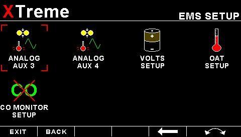
21 4.3 EMS Setup Page 21
22 Page RPM Setup RPM DISPLAY: Select if you want the RPM to be displayed in RPM or PERCENT.If you do not want any RPM information then set this parameter to "OFF". If the rotor RPM is set to "RPM" or "PERECENT" then the engine RPM display will automatically be enabled. RPM 100% DISPLAY: Select the maximum value that you want the RPM to correlate to 100%. RPM DISPLAY MAX: Select the maximum RPM that you want the RPM dial to show. This can give you increased display resolution. RPM DISPLAY MIN: Select the minimum RPM that you want the RPM dial to show. This can give you increased display resolution. HIGH ALARM: This enables or disables the RPM high alarm. HIGH ALARM: Enter the RPM threshold for when the high alarm must be activated. Any RPM value above this value will activate the alarm. HIGH CAUTION: Enter the RPM value for the high caution. This is the lower value of the upper yellow band. LOW CAUTION: Enter the RPM value for the low caution. This is the upper value of the lower yellow band. LOW ALARM: This enables or disables the RPM low alarm. LOW ALARM: Enter the RPM threshold for when the low alarm must be activated. Any RPM value below this value will activate the alarm.
23 Page 23 PULSES/REV: Enter the number of pulses per RPM. For engines with an uneven number of cylinders like three cylinder four stroke engines you can enter values containing fractions (usually 1.5 in this example). Most four stroke engines would generate one pulse for every two revolutions per cylinder. A four cylinder automotive four stroke engine would thus generate 2 pulses per revolution. A typical Rotax DCDI two stroke engine would generate 6 pulses per revolution. The well known Rotax 912/914 engine generates one pulse per revolution. RPM RESOLUTION: Select the step size between successive RPM values eg. if the RPM value is 4003 RPM and the RPM RESOLUTION is 5 then the actual value shown is 4005 RPM Rotor Setup ROTOR DISPLAY: Select if you want the rotor RPM to be displayed in RPM or PERCENT.If you do not want any rotor RPM information then set this parameter to off. If the rotor RPM is set to "RPM" or "PERECENT" then the engine RPM display will automatically be enabled. ROTOR 100% DISPLAY: Select the maximum value that you want the rotor RPM to correlate to 100%. HIGH ALARM: This enables or disables the Rotor RPM high alarm. HIGH ALARM: Enter the Rotor RPM threshold for when the high alarm must be activated. Any Rotor RPM value above this value will activate the alarm. HIGH CAUTION: Enter the Rotor RPM value for the high caution. This is the lower value of the upper yellow band. LOW CAUTION: Enter the Rotor RPM value for the low caution. This is the upper value of the lower yellow band. LOW ALARM: This enables or disables the Rotor low alarm.
24 Page 24 LOW ALARM: Enter the Rotor RPM threshold for when the low alarm must be activated. Any Rotor RPM value below this value will activate the alarm. PULSES/REV: Enter the number of pulses per rotor RPM. ROTOR RESOLUTION: Select the step size between successive Rotor RPM values eg. if the Rotor RPM value is 403 RPM and the ROTOR RESOLUTION is 5 then the actual value shown is 405 RPM.
25 Page EGT/CHT Setup EGT/CHT CHANNELS: Select the number of EGT or CHT channels you want to use. Choices are from 1 to 12. The temperature display will configure itself to make best possible use of the available display size. Please note that the minimum number of EGT & CHT channels that can be displayed is 1 and the maximum number of EGT and CHT channels that can be displayed is 12. EGT/CHT DISPLAY MAX: Select the maximum temperature that you want the EGT/CHT bargraph to show. This can give you increased display resolution. EGT/CHT DISPLAY MIN: Select the minimum temperature that you want the EGT/CHT bargraph to show. This can give you increased display resolution. HIGH ALARM: This enables or disables the EGT/CHT high alarm. HIGH ALARM: Enter the temperature threshold for when the high alarm must be activated. Any temperature above this value will activate the alarm. HIGH CAUTION: Enter the temperature value for the high caution.
26 Page 26 PROBE: Select if you are using a K-type, J-type or E-type thermocouple probe for the EGT/CHT group. All probes supplied by MGL Avionics are K-Type. J-types are sometimes used with American made CHT probes. All EGT probes are K-type. Etype probes are seldom used. TEMPERATURE UNIT: Select whether you want the EGT/CHT temperature to be displayed in degrees Celsius (ºC) or degrees Fahrenheit (ºF). MODE: A selection between HIGHEST or SCANNING can be selected. If HIGHEST is selected then the current highest thermocouple temperature is displayed. If SCANNING is selected then the unit will cycle through each thermocouple at the time specified in SCAN TIME. SCAN TIME: Specify the time that each of the channels must be displayed for. This menu option is only shown if SCANNING is selected for the display mode Special Rotax 912/914 probe mode In this mode the RDAC AUX 3 and AUX 4 analog input channels become the Rotax CHT channel 1 and CHT channel 2 respectively. All CHT setups must still be done under the CHT SETUP menu. The sender selection for the AUX 3 and AUX 4 must be set for OFF. A probe type of NTC must be selected for the probe setting in the CHT SETUP menu. The reason for using the NTC inputs is that the sensors Rotax use are standard NTC temperature probes and not of a thermocouple type.
27 Page Fuel Setup UNIT: Select your desired units for distance and fuel quantity. The following options are available: L/sm: Liters and statute miles G/sm: U.S. Gallons and statute miles L/nm: Liters and nautical miles G/nm: U.S. Gallons and nautical miles L/km: Liters and kilometer G/km: U.S. Gallons and kilometers SPEED: Select which speed will be used for fuel range/endurance based calulations. You can select beteween "AIRTALKAIRSPEED" which can be transmitted from an external airspeed indicator such as the MGL Avionics ASI-1/3 or "GPSGROUND SPEED". If a 2D or 3D GPS is not obtained and "GPS-GROUND SPEED" is selected then the XTreme-EMS will default to use the cruising speed for the fuel range/endurance calculations. FLOW 1/2: This enables or disables the Flow 1/2 display on the EFIS and MFD displays. KFACTOR 1/2: The K-Factor is the number of pulses generated by the fuel flow sender for one liter of fuel. The dual range fuel flow sender supplied by MGL Avionics has a K-Factor of 7000 in the low flow mode (jet installed) and 1330 for the high flow mode (no jet installed). The Flowscan 201A-6 has a K-Factor of You can use the K-Factor to calibrate your fuel flow sender. See the RDAC manual for more details on how to calibrate and install the fuel flow sender. MODE: Select if you want to measure fuel flow using a fuel flow sender or by using fuel injectors. FLOW MODE: If both fuel flow senders are selected then select if they are operating on individual fuel tanks (dual) or if they are operating in a supply/return type fuel system (differential). TANK 1/2 SETUP: Select this menu item to setup the fuel level for fuel tank 1/2. See below for more details.
28 Page 28 Fuel level setup. (Only tank 1 setup is shown, follow the same steps for tank 2 setup) TANK 1/2: Select if the fuel tank has a physical fuel level sender connected to it or if the Xtreme must use a calculation based virtual fuel tank. If you do not want any fuel level information then set this parameter to off. TANK SIZE: Enter the size of the fuel tank in your system. It is recommended to choose a size that is slightly less than the actual size so you can compensate for sender inaccuracies and give you a measure of reserve fuel. LOW ALARM: This enables or disables the fuel level low alarm. LOW ALARM: Enter your desired minimum fuel value that you would like to trigger the fuel low alarm. LOW CAUTION: Enter the fuel level value for the low fuel caution. CALIBRATE TANK: The fuel level sender needs to be calibrated before it can be used with this system. The calibration allows the system to learn the shape of your tank as well as any errors your fuel level sender or installation has. Regardless of your use of a fuel flow sender, you can install a fuel level sender into your fuel tank. These level senders are inexpensive and are available as after market replacement fittings from a car spares outlet. We recommend the senders available from VDO. Be aware that some makes of cheap level senders can prove troublesome, as the lever arms tend to be sticky. This prevents the floats from floating on the surface of the fuel at all times. As a consequence, this will lead to incorrect fuel level indication.
29 Page 29 Adjusting calibration points automatically Select SENDER for the MODE menu item. Once you have installed a fuel level sender into your tank, make sure the float can travel all the way from empty to full position without hindrance of any kind. The calibration procedure should be carried out with your aircraft in flight attitude. This means you need to lift the tail if you have a tail-dragger or lift the nose wheel if you have a weightshift trike. Calibration procedure Start the calibration procedure with an empty tank. Add five liters of fuel (our reserve quantity) using a suitable measure. Make sure the measure is suitably accurate. This is now the level sender reading at 0 Lt position. Move the highlight to this position and wait until the sender reading has stabilized (You will see the sender reading at the top line). This could take up to a minute so have patience. ENSURE THAT THE FLOAT IS NOT SUBMERGED AND IS FLOATING ON TOP OF THE FUEL LEVEL. Should this number not react to changes of your level sender position, then you have a problem. Please check your wiring according to the installation section of this manual. You should expect the number to change in the region of at least 20 to 60 counts per calibration position. If the number does not change with fuel level or only changes a very small amount check your installation. Something is not right! If you see the number changing then everything is well. Once it has stabilized and the highlight is on the 0 L position, press the rotary control to transfer the reading from the sender to the calibration point. Now you are ready for the next step. Add the required amount of fuel to get to the next level (In our case 9 Lt this is 20% tank capacity). Once done, wait for the reading to stabilize and press the rotary control again after you have moved the highlight to the 9 L position. Proceed in a similar manner until you have reached the last calibration position at 100% tank capacity. You are done! To finish your calibration, exit the calibration function by moving the highlight over the - - -PREVIOUS MENU - - menu item and press the rotary control. The instrument uses the 6 calibration points to work out a correction curve that takes into account the tolerances of your fuel level sender and the shape of your fuel tank. This results in an incredibly accurate and usable fuel level display that far exceeds that available from ordinary dial type gauges.
30 Page 30 Adjusting calibration points manually You may want to set individual calibration points manually. For example you may find that your fuel level is over reading at a specific fuel level. Correcting the tank level reading for this area can be simply done by adjusting the calibration point. You can do this by moving the float level with your hands to the desired position and then performing the calibration as outlined above, or you can use the manual option. Select MANUAL for the MODE menu item. Then highlight the point you want to change manually and press the rotary control. Use the rotary control to adjust the value. Press the rotary control when done. Note: The calibration positions may be edited by using the rotary control. This allows you, in theory, to copy calibration settings from one instrument to another. We however recommend that you do go though the calibration procedure even if the two aircraft are identical in all respects. Tolerances do exist and the calibration cancels these out. Accurate fuel level displays are a vital safety factor for an aircraft and a very useful feature for peace of mind during cross county flights. Notes on Slope error Sender value is a value determined by the XTreme. It is used to calculate fuel level, fuel endurance estimate and current range estimate. The fuel tank setup sender value can either increase in value as fuel is added or decrease in value if fuel is added. This is dependent on the type of fuel level sender used. However should the second reading be larger than the first reading all readings will have to be larger than the previous readings. Likewise should the second reading be smaller than the first reading all readings will have to be smaller than the previous reading. If this is not the case the wording "SLOPE ERROR" will be displayed. This could happen when fuel was removed instead of added between steps, no fuel was added between steps or when the fuel level sender was moved in the wrong direction e.g. moving the fuel level sender manually when it is not inserted in to the fuel tank. Determine the cause of the error if you should get a slope error message. If you do not know the cause of your error it is best to start from scratch. It should be remembered that accuracy in the fuel tank calibration is extremely important to enable your XTreme to display the correct data. TANK FILTER: Select the damping factor for the fuel level. A selection of "NONE", "LOW", "MED" or "HIGH" can be made.
 or")
31 Page Manifold Setup MAP DISPLAY: This enables or disables the manifold pressure display on the EMS displays screens MAP UNIT: Select if you want the manifold pressure displayed in mb (millibars) or Hg (inches of mercury). MAP DISPLAY MAX: Select the maximum pressure that you want the manifold bargraph in the EMS displays to show. This can give you increased display resolution. MAP DISPLAY MIN: Select the minimum pressure that you want the manifold bargraph in the EMS display to show. This can give you increased display resolution. HIGH ALARM: This enables or disables the manifold pressure high alarm. HIGH ALARM: Enter the pressure threshold for when the high alarm must be activated. Any pressure above this value will activate the alarm. HIGH CAUTION: Enter the pressure value for the high caution. This is the lower value of the upper yellow band. LOW CAUTION: Enter the pressure value for the low caution. This is the upper value of the lower yellow band. LOW ALARM: This enables or disables the manifold pressure low alarm. LOW ALARM: Enter the pressure threshold for when the low alarm must be activated. Any pressure below this value will activate the alarm.
32 Page 32 FILTER: This function can be used to select the signal filter time constant. Selections are "NONE", FAST or SLOW. This selection influences the rate at which your manifold pressure can change its reading. MAP CALIBRATION FACTOR: The sender in the RDAC is shipped uncalibrated. To calibrate the manifold pressure, compare and adjust the calibration factor until the manifold reading is the same as the pressure value in brackets. The pressure value in brackets is the barometer reading built into the Xtreme. The manifold pressure can only be calibrated in mb.
33 Page Oil Temperature Setup OIL TEMPERATURE DISPLAY: This enables or disables the oil temperature display on the EMS displays screens SENDER: Select what type of sender you are using. Select VDO for a VDO resistive sender, WESTACH for Westach thermistor type senders, MGL for a MGL NTC resistive temperature sender, LM335 for a MGL precision temperature sender or USER for a custom sender. The XTreme has a built in linearization curve for a standard 50ºC to 150ºC VDO resistive sender, Westach senders and the MGL NTC resistive sender. If the sender type is set to USER" CALIBRATE SENDER: If the sender type is set to USER, then use this menu option to calibrate your temperature sender. See section for more information. If the sender type is set to LM335" LM335: If the sender type is set to LM335, then use this menu option to calibrate your LM335 precision temperature sender. If recalibration is required then adjust the value using the rotary control until the temperature matches the reference ambient temperature. Please note that the LM335 can only be calibrated in degrees Celsius irrespective if the XTreme is setup to display temperature in Fahrenheit. Menu options for all sender types TEMPERATURE UNIT: Select whether you want the temperature to be displayed in degrees Celsius (ºC) or in degrees Fahrenheit (ºF). DISPLAY MAX: Select the maximum temperature that you want the oil temperature bargraph to show. This can give you increased display resolution.
34 Page 34 DISPLAY MIN: Select the minimum temperature that you want the oil temperature bargraph to show. This can give you increased display resolution. LOW ALARM: This enables or disables the oil temperature low alarm. LOW ALARM: Enter the temperature threshold for when the low alarm must be activated. Any temperature below this value will activate the alarm. LOW CAUTION: Enter the temperature value for the low caution. This is the upper value of the lower yellow band. HIGH CAUTION: Enter the temperature value for the high caution. This is the lower value of the upper yellow band. HIGH ALARM: This enables or disables the temperature high alarm. HIGH ALARM: Enter the temperature threshold for when the high alarm must be activated. Any temperature above this value will activate the alarm.
35 Page Oil Pressure Setup OIL PRESSURE DISPLAY: This enables or disables the oil pressure display on the EMS displays screens TYPE: Select if you are using a resistive, 4-20mA or 0-5V output pressure sender. If the RESISTIVE pressure sender is selected SENDER: Select what type of resistive pressure sender you are using. Select VDO for VDO / resistive senders, USER for a custom sender. MODEL: Select which VDO pressure sender you are using. A selection between a VDO 2, 5 or 10 Bar can be selected. If the 0-5V pressure sender is selected SENDER: Select the type of 0-5V sender used. Select UMA for UMA senders of USER for a custom 0-5V sender. MODEL: For UMA senders select the UMA model number. If the 4-20mA pressure sender is selected SENDER: Select the type of 4-20mA sender used. Select ROTAX for Rotax 912/ mA sender or USER for a custom 420mA sender. 4mA: Enter the pressure specified at 4mA output.
36 Page 36 20mA: Enter the pressure specified at 20mA output. If the USER" pressure sender is selected CALIBRATE SENDER: If the sender type is set to USER, then use this menu option to calibrate your pressure sender. See section for more information. Menu options for all sender types PRESSURE UNIT: Select whether you want to display the pressure in Bar, PSI or PSI(0.1). The PSI(0.1) is for low range pressure senders e.g. UMA 7PSI. DISPLAY MAX: Select the maximum pressure that you want the oil pressure bargraph to show. This can give you increased display resolution. DISPLAY MIN: Select the minimum pressure that you want the oil pressure bargraph to. This can give you increased display resolution. LOW ALARM: This enables or disables the pressure low alarm. LOW ALARM: Enter the pressure threshold for when the low alarm must be activated. Any pressure below this value will activate the alarm. LOW CAUTION: Enter the pressure value for the low caution. This is the upper value of the lower yellow band. HIGH CAUTION: Enter the pressure value for the high caution. This is the lower value of the upper yellow band. HIGH ALARM: This enables or disables the manifold pressure high alarm. HIGH ALARM: Enter the pressure threshold for when the high alarm must be activated. Any pressure above this value will activate the alarm.
37 Page Auxiliary analog 3/4 Setup The analog AUX3/4 channel on the RDAC is a general purpose channel that can be used for pressure as well as for temperature senders. FUNCTION: Select the function for the analog channel. Options are PRESSURE, TEMPERATURE, CURRENT or OFF. If the PRESSURE function is selected: TYPE: Select if you are using a resistive, 4-20mA or 0-5V output pressure sender. If the RESISTIVE pressure sender is selected SENDER: Select what type of resistive pressure sender you are using. Select VDO for VDO / resistive senders, USER for a custom sender. MODEL: Select which VDO pressure sender you are using. A selection between a VDO 2, 5 or 10 Bar can be selected. If the 0-5V pressure sender is selected SENDER: Select the type of 0-5V sender used. Select UMA for UMA senders of USER for a custom 0-5V sender.
38 Page 38 MODEL: For UMA senders select the UMA model number. If the 0-20mA pressure sender is selected SENDER: Select the type of 4-20mA sender used. Select ROTAX for Rotax 912/ mA sender or USER for a custom 420mA sender. 4mA: Enter the pressure specified at 4mA output. 20mA: Enter the pressure specified at 20mA output. If the USER" pressure sender is selected SENDER: Select the type of 4-20mA sender used. Select ROTAX for Rotax 912/ mA sender or USER for a custom 420mA sender. CALIBRATE SENDER: If the sender type is set to USER, then use this menu option to calibrate your pressure sender. See section for more information. Menu options for all sender types LABEL: Choose one of a selection of labels to suit your pressure input so you can identify it easily. PRESSURE UNIT: Select whether you want to display the pressure in Bar, PSI or PSI(0.1). The PSI(0.1) is for low range pressure senders e.g. UMA 7PSI. DISPLAY MAX: Select the maximum pressure that you want the bargraph to show. This can give you increased display resolution. DISPLAY MIN: Select the minimum pressure that you want the bargraph to show. This can give you increased display resolution. LOW ALARM: This enables or disables the pressure low alarm. LOW ALARM: Enter the pressure threshold for when the low alarm must be activated. Any pressure below this value will activate the alarm.
39 Page 39 LOW CAUTION: Enter the pressure value for the low caution. This is the upper value of the lower yellow band. HIGH CAUTION: Enter the pressure value for the high caution. This is the lower value of the upper yellow band. HIGH ALARM: This enables or disables the manifold pressure high alarm. HIGH ALARM: Enter the pressure threshold for when the high alarm must be activated. Any pressure above this value will activate the alarm. If the TEMPERATURE function is selected: SENDER: Select what type of sender you are using. Select VDO for a VDO resistive sender, WESTACH for Westach thermistor type senders, MGL for a MGL NTC resistive temperature sender, LM335 for a MGL precision temperature sender or USER for a custom sender. The XTreme has a built in linearization curve for a standard 50ºC to 150ºC VDO resistive sender, Westach senders and the MGL NTC resistive sender. If the sender type is set to USER" CALIBRATE SENDER: If the sender type is set to USER, then use this menu option to calibrate your pressure sender. See section for more information. If the sender type is set to LM335" LM335: If the sender type is set to LM335, then use this menu option to calibrate your LM335 precision temperature sender. If recalibration is required then adjust the value using the rotary control until the temperature matches the reference ambient temperature. Please note that the LM335 can only be calibrated in degrees Celsius irrespective if the XTreme is setup to display temperature in Fahrenheit.
40 Page 40 Menu options for all sender types LABEL: Choose one of a selection of labels to suit your temperature input so you can identify it easily. TEMPERATURE UNIT: Select whether you want the temperature to be displayed in degrees Celcius (ºC) or in degrees Fahrenheit (ºF). DISPLAY MAX: Select the maximum temperature that you want the bargraph to show. This can give you increased display resolution. DISPLAY MIN: Select the minimum temperature that you want the bargraph to show. This can give you increased display resolution. LOW ALARM: This enables or disables the temperature low alarm. LOW ALARM: Enter the temperature threshold for when the low alarm must be activated. Any temperature below this value will activate the alarm. LOW CAUTION: Enter the temperature value for the low caution. This is the upper value of the lower yellow band. HIGH CAUTION: Enter the temperature value for the high caution. This is the lower value of the upper yellow band. HIGH ALARM: This enables or disables the temperature high alarm. HIGH ALARM: Enter the temperature threshold for when the high alarm must be activated. Any temperature above this value will activate the alarm Calibrating the user defined pressure and Temperature Senders 1. Enter the number of points that you want to calibrate. 2. Enter the display reading that you want to show when the sender is at that actual display reading. 3. Enter the ADC (analog to digital converter) reading that corresponds to this display reading. The ADC reading is shown at the bottom of the display if you are applying the actual stimulus from the temperature or pressure sender. You can also manually enter this value if the ADC value is known or pre-calculated. 4. Continue entering display and ADC values until all the points have been entered. 5. Verify the above calibration by checking the temperature/pressure display versus the actual applied sender stimulus.
41 Page 41 If the CURRENT function is selected: DISPLAY MAX: Select the maximum current that you want the bargraph to show. This can give you increased display resolution. DISPLAY MIN: Select the minimum current that you want the bargraph to show. This can give you increased display resolution. LOW ALARM: This enables or disables the current low alarm. LOW ALARM: Enter the current threshold for when the low alarm must be activated. Any current below this value will activate the alarm. LOW CAUTION: Enter the current value for the low caution. This is the upper value of the lower yellow band. HIGH CAUTION: Enter the current value for the high caution. This is the lower value of the upper yellow band. HIGH ALARM: This enables or disables the current high alarm. HIGH ALARM: Enter the current threshold for when the high alarm must be activated. Any current above this value will activate the alarm. ZERO CURRENT SENSOR: Select this function to indicate to the XTreme that zero current is flowing through the MGL current monitor. This is best done with the MGL current monitor disconnected from the main current suppling conductor. CURRENT SPAN CALIBRATION: Enter the maximum value that your MGL current monitor can measure. This will depend on the distance and the method that is used to attach the MGL current monitor to the main current suppling conductor. It will be best if a multimeter can be inserted in series with the current supplying conductor and the span calibration adjusted until the XTreme matches that of the multimeter. Please see the MGL current monitor document for more information.
42 Page Volts Setup VOLTS DISPLAY MAX: Select the maximum value that you want the volts bargraph in the EMS display to show. This can give you increased display resolution. VOLTS DISPLAY MIN: Select the minimum value that you want the volts bargraph in the EMS display to show. This can give you increased display resolution. HIGH ALARM: This enables or disables the volts high alarm. HIGH ALARM: Enter the voltage threshold for when the high alarm must be activated. Any voltage above this value will activate the alarm. HIGH CAUTION: Enter the voltage for the high caution. This is the lower value of the upper yellow band. LOW CAUTION: Enter the voltage for the low caution. This is the upper value of the lower yellow band. LOW ALARM: This enables or disables the volts low alarm. LOW ALARM: Enter the voltage threshold for when the low alarm must be activated. Any voltage below this value will activate the alarm. VOLTS CALIBRATION FACTOR: Measure the battery voltage with a multimeter and then adjust this value to match that of the multimeters volts reading.
43 Page OAT Setup OAT TEMPERATURE UNIT: Select whether you want the OAT to be displayed in degrees Celsius (ºC) or in degrees Fahrenheit (ºF). OAT DISPLAY MAX: Select the maximum temperature that you want the OAT bargraph in the EMS display to show. This can give you increased display resolution. OAT DISPLAY MIN: Select the minimum temperature that you want the OAT bargraph in the EMS display to show. This can give you increased display resolution. HIGH ALARM: This enables or disables the OAT high alarm. HIGH ALARM: Enter the temperature threshold for when the high alarm must be activated. Any temperature above this value will activate the alarm. HIGH CAUTION: Enter the temperature for the high caution. This is the lower value of the upper yellow band. LOW CAUTION: Enter the temperature for the low caution. This is the upper value of the lower yellow band. LOW ALARM: This enables or disables the OAT low alarm. LOW ALARM: Enter the temperature threshold for when the low alarm must be activated. Any temperature below this value will activate the alarm. OAT CALIBRATION FACTOR: During the factory calibration a factor has been determined and entered here that will give you an accurate OAT reading. If you find this value is incorrect then adjust the calibration factor until the XTremes OAT matches that of a precision thermometer. Calibration can only be done in Celcius (ºC).
44 Page CO Monitor Carbon Monoxide Setup The CO Monitor Carbon Monoxide menu option allows the pilot to enable the CO Guardians Carbon Monoxide detector. The XTreme-EMS will display the carbon monoxide value on the EMS display as well as enable the carbon monoxide warning alarm. Please see the relevant CO Guardian detector manuals for more information. CO Monitor: Select which CO Monitor you are using. Select None to disable the CO display. RESET CO GUARDIAN: This will reset the CO Guardian Carbon Monoxide detector, perform a self test and then will re-enable the CO Guardian Carbon Monoxide detector.
45 Page GPS Setup GPS: Select OFF to disable the GPS information screen or select "EXTERNAL" if you have an external NMEA compatible GPS connected to the XTreme-EMS. If an external GPS is used then it must output the following NMEA sentences GGA - Global positioning system fix data RMC Recommended minimum specific GNSS data GSA GNSS DOP and active satellites GSV GNSS satellites in view NMEA stands for the National Marine Electronics Association. For more information please visit GPS BAUD RATE: Select the baud rate to match the external GPS receiver you are using. POSITION FORMAT: Select the display format of the GPS latitude and longitude. ALTITUDE UNIT: Select the unit of the altitude display. COG: Select if you want the COG to be related to true or magnetic north. LOCAL VARIATION: Select AUTO to allow the XTreme-EMS to automatically calculate the local variation or MANUAL for manual local variation input. AUTO LOCAL VARIATION: This item displays the calculated local magnetic variation. The XTreme-EMS will calculate the local variation every 10 minutes if a valid 2D or 3D GPS fix is obtained. MANUAL LOCAL VARIATION: This item allows the pilot to manually enter his local variation.
46 Page Timers Setup HOBBS MINIMUM RPM: Enter the RPM limit in which the Hobbs timer/maintenance timer must start incrementing. SET HOBBS TIME: This function allows you to set the engine Hobbs meter to any value. Typically, you would use this function to set the Hobbs meter to the current known engine time. Use the rotary control to change the value. Press the rotary control to accept and exit the menu option. If the Hobbs code is set to another value beside zero, then the pilot will be prompted to enter the Hobbs access code before allowing him to change the Hobbs time. This feature is useful for charted and flying school planes. CHANGE HOBBS CODE: This menu option allows you to change the Hobbs access code. You will first be prompted to enter the current code followed by entering in a new code followed by re-entering the new code. If the new code and the re-entered code is the same, then the Hobbs access code will be changed. Default code is 0000.

47 Page 47 SET MAINTENANCE TIMER: These timers allow you to keep track of engine maintenance interval. Set the timer when you have serviced your engine. A typical time might be 50 hours. This function allows you to set an engine maintenance timer. This timer is set in engine hours and it will count down to zero when the engine RPM is greater then the HOBBS MINIMUM RPM. A good use for this function is to set the hours until your next spark plug change or engine inspection. Use the rotary control to change the value. UTC OFFSET: Enter the UTC offset for your location. The UTC offset can be adjust in half an hour increments. RTC SOURCE: Select if you want the RTC UTC time to come from the GPS receiver or the internal RTC. Both real time clocks are powered by an internal 3V lithium coin cell battery. The internal battery can be replaced by unscrewing the 5 screws holding the back and front enclosures together as well as the 2 screws next to the D15 connector. Delicately slide out the electronics and replace the battery. The battery is a CR2032 coin cell. SET UTC DATE & TIME: Use the rotary control to set the UTC date & time in the internal RTC.
48 Page Data Recording Setup The XTreme-EMS has the ability to act as a black box recorder recording flight data directly onto an inserted SD card for later playback and investigation using the MGL Avionics Black Box viewer program. See the Black box viewer documents for further information. The Black box viewer can also convert the data into other file formats such as: KML: Keyhole Markup Language / Google Earth CSV: Comma-Separated Variable IGC: FAI Gliding commission The XTreme-EMS records the engine data as well as the GPS data (If an external GPS receiver is available) once per second WHEN A VALID FLIGHT IS DETECTED (AUTOMATIC OR MANUAL FLIGHT DETECT MODE). CREATE RECORDING FILE ON SD CARD: Selecting this menu option will create a file on the SD card (If inserted and not write protected) called enigma.rec with a fixed file size of 10MB. The reason behind the fixed file size of the recording file has to do with limited write cycles of the SD card and the instability of the MS-DOS file system. With a fixed file size, the XTreme-EMS never has to write to either the directory structure or FAT tables of the SD card eliminating wear of the card or possible data corruption. Once the recording file has been filled, the recording continues at the start of the file again, overwriting the oldest data in the file. The file size is large enough to record 5-20 hours of data depending on what data is recorded. DATA RECORDING ON: Selecting ON will enable the data recording functionality.


49 4.6.1 Examples of the exported flight data using CSV format and the KML format Page 49
 screen. SAVE SETTINGS TO SD CARD: Select this option to save all the XTreme-EMS settings to the SD card.")
50 Page Miscellaneous Setup AIRCRAFT REGISTRATION: Enter your aircraft registration. A maximum of 8 characters can be entered. The aircraft registration is displayed on the start up (Splash) screen. SAVE SETTINGS TO SD CARD: Select this option to save all the XTreme-EMS settings to the SD card. This is useful when setting up the instrument on the PC simulator and then later transferring the settings on the instrument itself. A file called XTREME.EMS will be created in the root directory of the SD card. RECALL SETTINGS FROM SD CARD: Select this option to recall all the XTreme-EMS settings from the SD card. This is useful when setting up the instrument on the PC simulator and then later transferring the settings to the instrument itself. The settings will be loaded from a file called XTREME.EMS in the root directory of the SD card.
 Screen Creating your own Startup (Splash) Screen You will need: A bitmap picture of your choice (*.")
51 Page ADC Values These values are mainly used for debugging purposes. Contact the MGL factory or your local dealer for more information. 5 Startup (Splash) Screen Creating your own Startup (Splash) Screen You will need: A bitmap picture of your choice (*.BMP, 480x272 pixel resolution) The Enigma BMP to MIF converter tool (can be downloaded free of charge from or can be found on the XTreme SD card). The Enigma BMP to MIF program is used to convert images in Windows BMP format to Enigma MIF format. You can use this program to make your own startup screen (Splash screen) and graphic information display screens. The color depth is limited to Enigmas 256 colors. Run the Enigma BMP image to MIF format converter program. Load an image file (and remember the location), select the resolution as width(480) and height (272) and press the process button. The new MIF image will be located in the same directory as the source (BMP) file. If the original file was not named Splash.BMP, rename the new *.MIF file to Splash.MIF, and copy the Splash.MIF file into the root directory of your SD card. The picture will be displayed when the unit is powered up.
52 Page 52 6 Loading factory default settings Press and hold the left and right most soft keys simultaneously on power up to load default factory settings. The following message will be displayed: 7 Alarm condition If an alarm condition occurs the following will happen: The item causing the alarm condition will flash on the screen An alarm warning message will be displayed on the screen An external alarm switch will close The alarm warning message and switch closure will remain until any button is pressed or until the condition(s) that activated the alarm no longer exist. The alarm output can be used to switch an external alarm indicator. The external alarm switch is an open collector transistor switch to ground with a maximum rating of 0.5A DC. It is possible to wire the alarm contacts of several Stratomaster instruments in parallel should this be desired. To avoid false activation of the alarms, the alarm function is only active 10 seconds after the instrument has powered up. 8 Cleaning The unit should not be cleaned with any abrasive substances. The screen is very sensitive to certain cleaning materials and should only be cleaned using a clean, damp cloth. Warning: The XTreme-EMS is not waterproof. Serious damage could occur if the unit is exposed to water and/or spray jets.
53 Page 53 9 XTreme-EMS Specifications Operating Temperature Range Storage Temperature Range Humidity Power Supply Current Consumption Display Dimensions ADC Enclosure Weight Alarm contact current rating Non-volatile memory storage Warm up time -10ºC to 50ºC (14ºF to 122ºF) -20ºC to 80ºC (-4ºF to 176ºF) <85% non-condensing 8 to 30Vdc SMPS (switch mode power supply) with built in 33V over voltage and reverse voltage protection Approx. 13.8V x272 pixel, 600 nits active matrix TFT LCD (Sunlight Readable). LED backlight is user adjustable. see section 12 for dimensional drawings 12 bits 100ksps 3 1/8 ABS, black in color, front mounting. See XTreme-EMS dimensional drawing Approx. 250 grams (XTreme-EMS unit only) Open collector transistor switch to ground. Maximum rating 0.5A DC write cycles 10 minutes

54 Page Installation 10.1 XTreme-EMS General Connection Diagram The use of an external 1A fuse is recommended. Connect the supply terminals to your aircraft s power supply. The XTreme-EMS can be used on both 12V and 24V without the use of any pre-regulators. Ensure that the supply voltage will not drop below 8V during operation as this may result in incorrect readings. Please see MGL Avionics RDAC documentation for installation and usage.


55 Page Xtreme-EMS DB15 Cable connections D15 Male NC=Not Connected DB 15 Pin 1 2 3,4,9, Color Red White Black NC NC NC NC Green NC NC Blue Purple Function 8-30Vdc power Alarm Output Ground RS232 Port 2 Transmit RS232 Port 2 Receive RS232 Port 1 Transmit RS232 Port 1 Receive OAT Probe CAN High CAN Low RDAC Signal Airtalk The XTreme-EMS has a D15 Female connector. The connecting cable must have a D15 male connector attached to it. 11 Firmware upgrades The XTreme-EMS' firmware can be upgraded in the field to the latest version via the SD card. This will keep your XTreme-EMS up to date with bug fixes and new features. The name of the firmware file must be called XTREME.FW and it must reside in the root directory of the SD card. When the XTreme-EMS powers up it will first look at the SD card to see whether the file exists, if it does then it will prompt the user to upgrade the firmware. Use the soft keys at the bottom to select whether to upgrade to the new firmware or to exit the firmware upgrade feature. The XTreme-EMS also provides a soft key to delete the XTREME.FW file from the SD card to avoid removing the SD card and deleting it with a PC. If the file does not exist, then the firmware upgrade function is bypassed and the XTreme-EMS' main program is executed. Please check regularly for the latest firmware releases.
All information is displayed in an easy to read format on a high resolution wide viewing angle 4.3 sunlight readable color display.
 XTreme - EMS Universal Engine Monitor Operating Manual English 1.02 Introduction The XTreme-EMS is a compact universal engine monitor. The XTreme-EMS, which fits a standard 3 1/8 instrument panel hole,
All information is displayed in an easy to read format on a high resolution wide viewing angle cd/m2 sunlight readable color display.
 Vega EMS-1 Universal Engine Monitoring System Operating Manual English 1.01 Introduction The Vega EMS-1 is a 2 1/4 (57mm) universal engine monitor color display instrument. The EMS-1 contains all the necessary
Temperatures can be displayed in degrees Celsius or degrees Fahrenheit from -100ºC to 1200ºC (-148ºF to 2192ºF).
.") Velocity TC-3 One to Twelve channel thermocouple (EGT/CHT) indicator Operating Manual English 1.02 Introduction The TC-3 thermocouple display unit is a 12 channel 3 1/8 instrument that contains all the
Velocity TC-3 One to Twelve channel thermocouple (EGT/CHT) indicator Operating Manual English 1.02 Introduction The TC-3 thermocouple display unit is a 12 channel 3 1/8 instrument that contains all the
The TC-4 is a 2 1/4 sunlight readable 4 channel thermocouple color display instrument.
 Vega TC-4 One to four channel thermocouple (EGT/CHT) indicator Operating Manual English 1.00 Introduction The TC-4 is a 2 1/4 sunlight readable 4 channel thermocouple color display instrument. The instrument
The E-3 can measure up to 4 EGT/CHT channels, a RPM input, a universal temperature sender input and a universal pressure sender input.
 E-3 Universal engine monitor Operating Manual English 1.01 Introduction The E-3 universal engine monitor combines in one compact 2.25 format instrument all that is needed to monitor the majority of smaller
Blaze TC-6. Introduction. 1 Features. Twelve channel thermocouple (EGT/CHT) indicator. Operating Manual English 1.00
 indicator. Operating Manual English 1.00") Blaze TC-6 Twelve channel thermocouple (EGT/CHT) indicator Operating Manual English 1.00 Introduction The TC-6 is a 3 1/8 sunlight readable 12 channel thermocouple color display instrument that contains
Blaze TC-6 Twelve channel thermocouple (EGT/CHT) indicator Operating Manual English 1.00 Introduction The TC-6 is a 3 1/8 sunlight readable 12 channel thermocouple color display instrument that contains
FF-1. Introduction. 1 Features. Fuel management computer for single or dual fuel tanks. Operating Manual English 1.04
 FF-1 Fuel management computer for single or dual fuel tanks Operating Manual English 1.04 Introduction The FF-1 fuel management computer is a 2.25 instrument intended for efficient monitoring of fuel related
E-1. Introduction. 1 Features. Universal engine monitor. Operating Manual English 1.00
 E-1 Universal engine monitor Operating Manual English 1.00 Introduction The E-1 universal engine monitor combines in one compact 3.125 format instrument all that is needed to monitor the majority of smaller
FF-3. Introduction. Fuel management computer for single or dual fuel tanks. Operating Manual English 1.02
 FF-3 Fuel management computer for single or dual fuel tanks Operating Manual English 1.02 Introduction The FF-3 fuel management computer is a 3 1/8 instrument intended for efficient monitoring of fuel
EMS-2. Introduction. Features. Engine Management System. Operating Manual English 1.07
 EMS-2 Engine Management System Operating Manual English 1.07 Introduction The EMS-2 is a multifunction engine information display and early warning engine monitoring system. It has been specifically designed
In addition, the FF-4 can use the actual ground speed from a RS232 NMEA enabled GPS receiver to determine fuel range.
 Vega FF-4 Fuel Computer Operating Manual English 1.00 Introduction The FF-4 is a 2 1/4 sunlight readable color display instrument intended for efficient monitoring of fuel related information for single
ASI-3. Introduction. 1 Features. Airspeed Indicator (ASI) with automatic flight log. Operating Manual English 1.01
 with automatic flight log. Operating Manual English 1.01") ASI-3 Airspeed Indicator (ASI) with automatic flight log Operating Manual English 1.01 Introduction The ASI-3 airspeed indicator is a 3 1/8 instrument that provides a wide range airspeed indication in
ASI-3 Airspeed Indicator (ASI) with automatic flight log Operating Manual English 1.01 Introduction The ASI-3 airspeed indicator is a 3 1/8 instrument that provides a wide range airspeed indication in
RV-3. Introduction. 1 Features. Universal engine RPM and rotor RPM indicator. Operating Manual English 1.00
 RV-3 Universal engine RPM and rotor RPM indicator Operating Manual English 1.00 Introduction The RV-3 universal engine RPM and rotor RPM unit is a 3 1/8 instrument providing a universal RPM counter that
ASI-1. Introduction. 1 Features. Airspeed Indicator (ASI) with automatic flight log. Operating Manual English 1.06
 with automatic flight log. Operating Manual English 1.06") ASI-1 Airspeed Indicator (ASI) with automatic flight log Operating Manual English 1.06 Introduction The ASI-1 airspeed indicator is a 2 1/4 instrument that provides a wide range airspeed indication in
ASI-1 Airspeed Indicator (ASI) with automatic flight log Operating Manual English 1.06 Introduction The ASI-1 airspeed indicator is a 2 1/4 instrument that provides a wide range airspeed indication in
MAP-1. Introduction. 1 Features. Manifold Pressure and RPM Indicator. Operating Manual English 1.03
 MAP-1 Manifold Pressure and RPM Indicator Operating Manual English 1.03 Introduction The MAP-1 is a 2 1/4 instrument which can measure pressures in the range of 0.25 bars (3.6 PSI) to 2.5 bars (36.2 PSI)
MGL Avionics EFIS G2 and iefis
 MGL Avionics EFIS G2 and iefis Guide to using the MGL RDAC CAN interface with the LAD AERO Injection Kit on ROTAX 912-912S General... 3 Data connections... 3 LAD AERO ROTAX 912 engine data from ECU...
GENERAL The AuRACLE Engine Management System primary display provides a graphical representation of the following engine instrumentation:
 GENERAL The AuRACLE Engine Management System primary display provides a graphical representation of the following engine instrumentation: o Manifold Pressure (MAP) o RPM o Fuel Flow (FF) o Turbine Inlet
FL-100-R (109) Operations and Installation Manual
 Operations and Installation Manual") Page 1 of 23 All specification subject to change 2002-2005 FL-100-R (109) Operations and Installation Manual This manual is certified for use with instrument serial number ASL000000 Use of this manual
Page 1 of 23 All specification subject to change 2002-2005 FL-100-R (109) Operations and Installation Manual This manual is certified for use with instrument serial number ASL000000 Use of this manual
Stratomaster Maxi Single
 Stratomaster Maxi Single TP-2 Combined Oil or fuel pressure gauge Oil or Coolant temperature gauge The TP-2 Temperature/Pressure gauge is a 3.5 instrument intended for display of either the following selections:
CGR-30P PREMIUM Worksheet
 Rev: D CGR-30P PREMIUM Worksheet Replace your Tachometer with the CGR-30P Download this file, fill it out and then save it. Include it with your order. www.buy-ei.com General Info: Aircraft Information:
EFMS100 USER MANUAL Revision 1.1
 Table of content EFMS100 USER MANUAL Revision 1.1 1 Key specifications and benefits... 1 2 Detailed specifications... 3 2.1 Engine tachometer... 3 2.2 Engine hour meter... 3 2.3 Thermometers... 3 2.4 Battery
EGT-100 Operations and Installation Manual
 Page 1 of 11 All specification subject to change 2002-2005 EGT-100 Operations and Installation Manual This manual is certified for use with instrument serial number ASL000000 Use of this manual with any
Stratomaster Maxi Single
 Stratomaster Maxi Single RV-3 Universal Engine RPM and Rotor RPM display The RV-3 unit is a 3.5 instrument providing a universal rev counter that can be adapted to a variety of roles. Typical uses are
RDAC X. Technical installation document
 RDAC X Technical installation document Models: A 4TC channels B 12TC channels C 4TC channels plus Manifold pressure sender D 12TC channels plus Manifold pressure sender RDAC X general The RDAC X consists
Vega AHRS-1 / MAG-1. Introduction. 1 Features. Artificial Horizon and Magnetic Compass indicator Magnetic Compass Indicator
 Vega AHRS-1 / MAG-1 AHRS-1: MAG-1: Artificial Horizon and Magnetic Compass indicator Magnetic Compass Indicator Operating Manual English 1.01 Introduction The AHRS-1 / MAG-1 is a 2 1/4 sunlight readable
ENGINE MONITORING SYSTEM OPERATOR'S MANUAL. Release: M. MGL Avionics. P O Box 286 Sundowner 2161 South Africa
 Table of Contents ENGINE MONITORING SYSTEM OPERATOR'S MANUAL Release: 020826M MGL Avionics P O Box 286 Sundowner 2161 South Africa Email: rainier@iafrica.com Web: http://users.iafrica.com/r/ra/rainier/strato.htm
Stratomaster Ultra for Rotorcraft
 Stratomaster Ultra for Rotorcraft Model RL with RDAC V EMS Owner's Manual & Installation guide MGL Avionics Physical: 5 Fuchsia Street, Heldervue, Somerset West Postal: Postnet Suite 325, Private Bag X15,
This document set is applicable to the following part number configurations:
 This document set is applicable to the following part number configurations: Four Cylinder Exhaust Gas and Cylinder Head Temperature Part Number Kit Configuration Instrument Thermocouples ECT204 ECT204
PowerView PV380-R2 Mechanical Configuration
 PowerView PV380-R2 Mechanical Configuration Operations Manual *Products covered in this document comply with European Council electromagnetic compatibility directive 2004/108/EC and electrical safety directive
Fuel Level FL1. FL1 - User s manual. Rev Revision#2.0, 28/11/2014 For firmware version 1.2
 Fuel Level FL1 Revision#2.0, 28/11/2014 For firmware version 1.2 FL1 - User s manual Page intentionally left blank SECTIONS MECHANICAL INSTALLATION ELECTRICAL INSTALLATION OPERATING INSTRUCTIONS INSTRUMENT
Indicating. 1. General. A. Fuel Quantity. B. Fuel Flow
 Indicating GENERAL 28-40: INDICATING. General A. Fuel Quantity A dual reading fuel quantity indicator is displayed in the Fuel Qty block of the ENGINE page along calibrated vertical bars. The fuel quantity
Stratomaster Maxi Single
 Stratomaster Maxi Single MAP-2 Universal pressure monitor The MAP-2 is a 3.5 instrument which can measure pressures in the range from 0.25 bars (3.6 PSI) to 2.5 bars (36.2 PSI). Pressure can be displayed
Stratomaster Smart Single
 Stratomaster Smart Single Universal Engine RPM and Rotor RPM display The unit is a 2.25 instrument providing a universal rev that can be adapted to a variety of roles. Typical uses are engine RPM displays
THIS MANUAL DESCRIBES THE SMARTCRAFT GAUGE SYSTEMS AVAILABLE FOR YOUR BOAT
 Systems Monitor Operation Manual THIS MANUAL DESCRIBES THE SMARTCRAFT GAUGE SYSTEMS AVAILABLE FOR YOUR BOAT 2004, Mercury Marine 90-895202 204 0 TABLE OF CONTENTS Legend..............................................
NexSysLink. Operation Manual. NMEA 2000 SAE J1939 Indmar Engines. CAN Instruments Product Family
 NexSysLink CAN Instruments Product Family Operation Manual NMEA 2000 SAE J1939 Indmar Engines Contact Beede Beede Electrical Instrument Company, Inc. 88 Village Street Penacook, NH 03303 (603) 753-6362
Effective March 1, 2018
 SYSTEM PRICE LIST Effective March 1, 2018 and STC d SINGLE Engine EDM-700/800, 4,6,7,8,9 Cyl. TSO Display s EGT s, CHT s, TIT or Oil Temp (digital and bar graph display). Other temperatures & functions
G1000TM. engine indication system pilot s guide for the Diamond DA40
 G1000TM engine indication system pilot s guide for the Diamond DA40 Record of Revisions Revision Date of Revision Revision Page Range Description A 05/31/05 7-1 7-7 Initial release. Garmin G1000 EIS Pilot
MVP-50P. Marking and Configuration Requirements for Certified Aircraft
 Accurate CHT Measurements Marking and Configuration Requirements for Certified Aircraft ELECTRONICS INTERNATIONAL MVP-50P Marking and Configuration Requirements for Certified Aircraft Electronics International
Stratomaster Smart Single
 Stratomaster Smart Single GF-1 Tilt compensated dual range aviation G force meter The GF-1 is a 2.25 instrument that displays the acceleration forces acing on the aircraft. Able to measure out of vertical
CNV-AT. Introduction. 1 Features. Airtalk serial altitude to parallel Gillham code for mode C transponders. Operating Manual English 1.
 CNV-AT Airtalk serial altitude to parallel Gillham code for mode C transponders Operating Manual English 1.00 Introduction The CNV-AT converter accepts the altitude and local pressure setting information
USER'S MANUAL FOR THE ENGINE INFORMATION SYSTEM
 USER'S MANUAL FOR THE ENGINE INFORMATION SYSTEM Grand Rapids Technologies Incorporated 889 76th St SW #2 Byron Center, MI 49315 (616) 583-8000 Fax (616) 583-8001 1 1. USING THIS MANUAL... 5 2. USING THE
Effective March 2, SINGLE Engine EDM-700/800, 4,6,7,8,9 Cyl. TSO and STC d
 SYSTEM PRICE LIST Effective March 2, 2018 SINGLE Engine EDM-700/800, 4,6,7,8,9 Cyl. TSO and STC d Display s EGT s, CHT s, TIT or Oil Temp (digital and bar graph display). Other temperatures & functions
2007 Mercury Marine SmartCraft Gauges
 i 27 Mercury Marine SmartCraft Gauges 9-89828315 97 ii TABLE OF CONTENTS System Tachometer/Speedometer Basic Operation and Features...1 Automatic Engine Detection Feature...1 Master Reset...2 Alarm Warnings...3
Welcome to ABB machinery drives training. This training module will introduce you to the ACS850-04, the ABB machinery drive module.
 Welcome to ABB machinery drives training. This training module will introduce you to the ACS850-04, the ABB machinery drive module. 1 Upon the completion of this module, you will be able to describe the
Hot Tach Pro Operation Manual. Competition Systems, Inc Vista Terrace Lake Forest, CA (949)
") Hot Tach Pro Operation Manual Competition Systems, Inc. 26806 Vista Terrace Lake Forest, CA 92630 (949) 580-6898 Hot Tach Pro Operation Manual Revsion:4/2000 Hot Tach Pro Operation Manual Revsion:4/2000
Hot Tach Pro Operation Manual Competition Systems, Inc. 26806 Vista Terrace Lake Forest, CA 92630 (949) 580-6898 Hot Tach Pro Operation Manual Revsion:4/2000 Hot Tach Pro Operation Manual Revsion:4/2000
Lingenfelter NCC-002 Nitrous Control Center Quick Setup Guide
 Introduction: Lingenfelter NCC-002 Nitrous Control Center Quick Setup Guide The NCC-002 is capable of controlling two stages of progressive nitrous and fuel. If the NCC-002 is configured only for nitrous,
Issue 2.0 December EPAS Midi User Manual EPAS35
 Issue 2.0 December 2017 EPAS Midi EPAS35 CONTENTS 1 Introduction 4 1.1 What is EPAS Desktop Pro? 4 1.2 About This Manual 4 1.3 Typographical Conventions 5 1.4 Getting Technical Support 5 2 Getting Started
MATRIX LLC LEVEL CONTROL PANEL
 MATRIX LLC LEVEL CONTROL PANEL Installation Operation Maintenance Manual 1-26-09 REV-0.3 1 INDEX Introduction. 3 Product Configurations..... 4 I/O Descriptions. 8 Operation o Intercooler, Accumulator,
Glow Plug for E Series Only
 Charging the Battery - Do not charge the battery, with a charger using negative discharge pulses, when connected to the ECU. This will destroy the electronics of the ECU. The only method is to disconnect
Installation guide for the Stratomaster Flight digital aircraft instrument Page 1
 Installation guide for the Stratomaster Flight digital aircraft instrument Page 1 Before you commence any attempt at installing this instrument it is your duty to familiarize yourself with the relevant
Installation and User Manual. with RAIN SENSOR.
 with RAIN SENSOR www.solarsmartopener.com Revision..0 TABLE OF CONTENTS Features In The Box Further Items Required Basic Operation Solar Panel and Operator Installation Operator Installation Solar Panel
RDAC XF RDAC XF and RDAC XF MAP
 RDAC XF RDAC XF and RDAC XF MAP RDAC XF MAP version has a map sensor fitted. Input Connections TC 1 to 12 Inputs for use with thermocouple temperature probes. Typcally used for EGT probes (K-types) and
EDM-700/760/790/800/900/930 & 450 SYSTEM PRICE LIST
 EDM-700/760/790/800/900/930 & 450 SYSTEM PRICE LIST Effective July 1 2016 ALL EDM SYSTEMS are TSO d and INCLUDES as free: LeanFind (tm) Performs ROP and LOP, automatically finds the first and last cylinder
Advanced User Manual
 Advanced User Manual Banks SpeedBrake For use with Palm Tungsten E2 2004-2005 Chevy/GMC 6.6L (LLY) Turbo-Diesel Pickup THIS MANUAL IS FOR USE WITH KITS 55419 & 55421 Gale Banks Engineering 546 Duggan Avenue
Fuel Flow / Pressure (FP-5 and FP-5L) Operating Instructions
 Operating Instructions") Fuel Flow / Pressure (FP-5 and FP-5L) Operating Instructions OI 0505931 5/5/93 Rev. H: 2/17/05 You must read this manual before installing or operating the instrument. This manual contains warranty and
Fuel Flow / Pressure (FP-5 and FP-5L) Operating Instructions OI 0505931 5/5/93 Rev. H: 2/17/05 You must read this manual before installing or operating the instrument. This manual contains warranty and
Water Specialist PR Control Valve Programming and Cover Drawing Manual
 Water Specialist PR Control Valve Programming and Cover Drawing Manual Page 2 PR Man u al PR Manual Page 3 Table of Contents PR Front Cover and Drive Assembly...4 OEM General Programming Instructions...5
RDAC XG Engine monitoring module for MGL Avionics CAN bus compatible EFIS systems.
 RDAC XG Engine monitoring module for MGL Avionics CAN bus compatible EFIS systems. This Engine monitor is fully compatible with the larger RDAC XF device. Compared to the RDAC XF the following inputs are
EMS-2. Introduction. 1 Features. Engine Monitoring System. Operating Manual English 1.12
 EMS-2 Engine Monitoring System Operating Manual English 1.12 Introduction The EMS-2 is a multifunction engine information display and early warning engine monitoring system. It has been specifically designed
RDAC X. Technical installation document
 RDAC X Technical installation document Models: A 4TC channels B 12TC channels C 4TC channels plus Manifold pressure sender D 12TC channels plus Manifold pressure sender RDAC X general The RDAC X consists
Preparing and programming of ESGI 2 LPG supply system manual
 Preparing and programming of ESGI 2 LPG supply system manual Part II Instruction of preparing and programming the ESGI system 1 Technical data of the central unit Vs Power supply voltage 0...16V V i_an
EDM-700/760/800/900/930 & 450 SYSTEM PRICE LIST
 EDM-700/760/800/900/930 & 450 SYSTEM PRICE LIST Effective February 1, 2013 ALL EDM SYSTEMS are TSO d and INCLUDES as free: LeanFind (tm) Performs ROP and LOP, automatically finds the first and last cylinder
CS 420RC. Solid De-icer Controller Configuration and Set-up Manual
 CS 420RC Solid De-icer Controller Configuration and Set-up Manual 2/15 Table of Contents 1 Systems Modes of Operation 3 2 System Features 4 3 System Description 5 4 System Specifications 6 4.1 CS-420RC
Sunbeam Alpine Series III, IV, and V Fuel & Temperature Gauges by Michael Hartman and Thomas Hayden Version 1.4 May 9, 2018
 Sunbeam Alpine Series III, IV, and V Fuel & Temperature Gauges by Michael Hartman and Thomas Hayden Version 1.4 May 9, 2018 The Circuit Illustration 1: Temperature & Fuel Gauge Circuits (Series V) Example
Operation Manual. For technical help please contact Livorsi Marine at or us at
 For technical help please contact Livorsi Marine at 4-5- or email us at info@livorsi.com This Operation Manual system is compatible with any Smartcraft, NMEA, J99 or Indmar engine. Livorsi Marine Inc 5
MODEL MVX-2011 TANK MOUNT SPEEDOMETER/TACHOMETER
 MODEL MVX-2011 TANK MOUNT SPEEDOMETER/TACHOMETER Wiring Diagram The MVX-2011 gauges will work on 2011-up Softail models with 5 gauges or 2012-up Dyna models with 5 gauges. It is a direct plug in on these
XC Instrumentation System Owner s Manual Revision /05/06
 XC Instrumentation System Owner s Manual Revision 3.0 07/05/06 XC INSTRUMENTATION SYSTEM OWNER S MANUAL 1 Revision History Date New Revision Level Revision Description 11/08/05 1.0 Initial release 05/24/06
PowerSTAR PS-2024-D. Maximum Power Point Tracking Solar Regulator. w w w. r o c s o l i d. c o m. a u. Contents
 w w w. r o c s o l i d. c o m. a u PowerSTAR PS-2024-D Maximum Power Point Tracking Solar Regulator Contents 1 Quick Start Guide... 2 2 Specifications... 3 2.1 General Operation... 3 2.2 Absolute Maximum
MAP Sensor. Technical Spec COPY RIGHTS ECOTRONS ALL RIGHTS RESERVED ECOTRONS LLC. -Manifold Absolute Pressure Sensor
 MAP Sensor -Manifold Absolute Pressure Sensor Technical Spec ECOTRONS LLC COPY RIGHTS ECOTRONS ALL RIGHTS RESERVED Note: If you are not sure about any specific details, please contact us at info@ecotrons.com.
CIRRUS AIRPLANE MAINTENANCE MANUAL
 ANALYZERS - ENGINE MONITORING. DESCRIPTION This section describes that portion of the engine indicating system which is used to analyze engine performance, temperature, and condition. Serials 00 thru 8
CS 430RC. Solid De-icer Controller Configuration and Set-up Manual
 CS 430RC Solid De-icer Controller Configuration and Set-up Manual 2/17 Table of Contents 1 Systems Modes of Operation 3 2 System Features 4 3 System Description 5 4 System Specifications 6 4.1 CS-430RC
BMS16. Thanks for your purchasing the BMS16 for your vehicle.
 BMS16 BMS for 2S-16S LiPo & LiFe Low power consumption High accuracy 2.8 TFT LCD display Programmable Thanks for your purchasing the BMS16 for your vehicle. Read the ENTIRE instruction manual to become
BMS24. Thanks for your purchasing the BMS24 for your vehicle.
 BMS24 for 2S-24S LiPo & LiFe Low power consumption High accuracy 2.8 TFT LCD display Programmable Thanks for your purchasing the BMS24 for your vehicle. Read the ENTIRE instruction manual to become familiar
ICL Three Pump Controller
 ICL Three Pump Controller Pump Operation The number of pumps that the program controls can be selected by enabling only the ones that are currently installed and in service. The enable/disable setting
RDAC VD. Technical installation document
 RDAC VD Technical installation document RDAC VD general The RDAC model VD is an integrated, microprocessor controlled engine monitoring subsystem. It is intended for installation close to the engine, inside
Service Manual BLACK DIAMOND SERVICE MANUAL. V.160 November
 BLACK DIAMOND SERVICE MANUAL V.160 November 2011 www.montrealchargeur.com www.battelec.ca www.doctorfleet.com Page 1/30 1. SAFETY PRECAUTIONS 1 Before to start using the Black Diamond Charger, read these
IS0306 rev. B ecn /2013. MG Tachometer (NMEA2000 and J-1939) TACH 1760 RPM FUEL. Installation / User Manual.
 TACH 1760 RPM FUEL. Installation / User Manual.") IS0306 rev. B ecn 9055 11/2013 MG3000 - Tachometer (NMEA2000 and J-1939) TACH 1760 RPM FUEL Installation / User Manual www.faria-instruments.com IMPORTANT: This User s Guide outlines the functionality
IS0306 rev. B ecn 9055 11/2013 MG3000 - Tachometer (NMEA2000 and J-1939) TACH 1760 RPM FUEL Installation / User Manual www.faria-instruments.com IMPORTANT: This User s Guide outlines the functionality
Overview of operation modes
 Overview of operation modes There are three main operation modes available. Any of the modes can be selected at any time. The three main modes are: manual, automatic and mappable modes 1 to 4. The MapDCCD
Combined Ventilation Controller RVWS-T-224HA
 Combined Ventilation Controller RVWS-T-224HA 8-stage Control for Power/Natural Applications 2 variable speed stages, 2 curtain winch stages, 2 fixed speed ventilation stages, 1 thermo/mister cycle stage
Setup Tabs. Basic Setup: Advanced Setup:
 Setup Tabs Basic Setup: Password This option sets a password that MUST be entered to re-enter the system. Note: ProEFI can NOT get you into the calibration if you lose this password. You will have to reflash
Automatic Genset Controller, AGC-4 Display readings Push-button functions Alarm handling Log list
 OPERATOR'S MANUAL Automatic Genset Controller, AGC-4 Display readings Push-button functions handling Log list DEIF A/S Frisenborgvej 33 DK-7800 Skive Tel.: +45 9614 9614 Fax: +45 9614 9615 info@deif.com
Product Manual. Part Number: MVP-193 Mefi-6 ECU Revision: 1.0
 Product Manual Part Number: MVP-193 Mefi-6 ECU Revision: 1.0 Copyright Controls, Inc. P.O. Box 368 Sharon Center, OH 44274 Phone 330.239.4345 Fax 330.239.2845 www.controlsinc.com TABLE OF CONTENTS PRIOR
SPA MICROPROCESSOR 3 STAGE PROGRAMMABLE SHIFT LIGHT INSTALLATION AND OPERATING MANUAL PAGE 2...INSTRUMENT FEATURES. PAGE 3...OPERATING INSTRUCTIONS.
 SPA MICROPROCESSOR 3 STAGE PROGRAMMABLE SHIFT LIGHT INSTALLATION AND OPERATING MANUAL PAGE 2...INSTRUMENT FEATURES. PAGE 3...OPERATING INSTRUCTIONS. PAGE 4...MENU SYSTEM. PAGE 6...SPECIFICATIONS. PAGE
VOLUMETRIC BLENDING SYSTEM OPERATION MANUAL
 VOLUMETRIC BLENDING SYSTEM OPERATION MANUAL 12285 E. MAIN ST. MARSHALL, IL 62441 PHONE: 217-826-6352 FAX: 217-826-8551 WEB SITE: www.yargus.com 1 OPENING SCREEN The OPENING SCREEN is the screen that the
PCT-3001 plus. Display LCD
 PCT3 plus DIGITAL PRESSURE CONTROLLER FOR COOLING PLANTS DESCRIPTION Pressure controller for refrigeration systems capable to control suction (compressors) and discharge (fans) pressures. It is possible
Subaru BRZ Toyota GT86 Scion FR-S
 RaceROM Features for Subaru BRZ Toyota GT86 Scion FR-S v1.8 Index Warning... 3 Introduction... 4 Feature list... 4 Supported Vehicle Models... 4 Availability... 4 Overview... 5 Map Switching**... 5 Speed
ODYR-25-1 & SLX-25-1 rev. A VACUUM/BOOST PRESSURE, TEMP, and EGT GAUGE
 ODYR-25-1 & SLX-25-1 rev. A VACUUM/BOOST PRESSURE, TEMP, and EGT GAUGE SENSOR CONNECTION: The vac./boost sensor has 1/8 NPT on the end which can be treaded into the intake track, or into a pipe adapter
SECTION 3 ENGINE INDICATION SYSTEM (EIS)
") ENGINE INDICATION SECTION ENGINE INDICATION () NOTE: Refer to the Pilot s Operating Handbook (POH) for limitations. The Engine Indication System () displays critical engine, electrical, fuel, and other
ENGINE INDICATION SECTION ENGINE INDICATION () NOTE: Refer to the Pilot s Operating Handbook (POH) for limitations. The Engine Indication System () displays critical engine, electrical, fuel, and other
Quick Setup Guide for IntelliAg Model YP Air Pro
 STEP 1: Pre-Programming Preparation: The Quick Guide assumes the Virtual Terminal, Master Switch, Working Set Master, Working Set Member, and all sensors have been connected and properly installed. Reference
MoistureMatch A next generation grain tester
 MoistureMatch A next generation grain tester A next generation moisture tester incorporating new and unique technology. Finally, a portable tester that will more accurately match and track with the commercial
Electronics International inc.
 Electronics International inc. MVP-50T Marking and Configuration Requirements Rev B: 6/24/11 Electronics International Inc. will configure the MVP-50T to the range limits, markings and hardware outlined
SPA MICROPROCESSOR COMBINED TACHO&SPEEDO/GAUGE INSTALLATION AND OPERATING MANUAL PAGE 2...INSTRUMENT FEATURES PAGE 3...OPERATING INSTRUCTIONS
 SPA MICROPROCESSOR COMBINED TACHO&SPEEDO/GAUGE INSTALLATION AND OPERATING MANUAL PAGE 2...INSTRUMENT FEATURES PAGE 3...OPERATING INSTRUCTIONS PAGE 3...MENU SYSTEM PAGE 9...INSTALLATION DIAGRAMS PAGE 13...INSTALLATION
Online Capacity Tester MK70 User and PC-Software Manual
 Online Capacity Tester MK70 User and PC-Software Manual User manual Online-Battery-Tester - 2 User manual Online-Battery-Tester - 3 Introduction: With this processor controlled capacity tester you can
Quick Setup Guide for IntelliAg Model YP40 20 Air Pro
 STEP 1: Pre-Programming Preparation: The Quick Guide assumes the Virtual Terminal, Master Switch, Working Set Master, Working Set Member, and all sensors have been connected and properly installed. Reference
MODEL MCL-3212 SPEEDOMETER/TACHOMETER for 2012 up Dyna and Softail with 4 gauge
 MODEL MCL-3212 SPEEDOMETER/TACHOMETER for 2012 up Dyna and Softail with 4 gauge IMPORTANT NOTE! This gauge has an odometer preset option that is only available one time in the first 100 miles (160km) of
51 & 52 Series II. Users Manual. Thermometer. Test Equipment Depot Washington Street Melrose, MA TestEquipmentDepot.
 51 & 52 Series II Thermometer Test Equipment Depot - 800.517.8431-99 Washington Street Melrose, MA 02176 - TestEquipmentDepot.com Users Manual English September 1999 Rev.2, 11/10 1999-2010 Fluke Corporation,
SMT-150 Installer Manual
 SMT-150 Installer Manual 3 Stage Digital HVAC Controller Version 1.0 Version History January 2019 Version 1 - Original Document Thank you for your purchase of this premier product. Please take the time
18 October, 2014 Page 1
 19 October, 2014 -- There s an annoying deficiency in the stock fuel quantity indicator. It s driven by a capacitive probe in the lower/left tank, so the indicator reads full until the fuel is completely
Draft Unofficial description of the UNRC charger menus
 Table of contents 1. The main screen... 2 2. Charge modes overview... 2 3. Selecting modes... 3 4. Editing settings... 3 5. Choose default charge mode... 4 6. Edit memory banks... 4 7. Charge mode description...
Model H30 Operation Manual
 Model H30 Operation Manual Model H30 Version 1.0 August 1, 2007 2 135 West Davenport Street Rhinelander WI 54501 Phone: 866.441.7997 Fax: 866.278.0036 info@houstonst.com www.houstonst.com 3 Table of Contents
WP37 & HT37 User Manual
 WP37 & HT37 User Manual Origio WP37 & HT37 Warming Plates & Heated Trolley Warming Plates WP37 300 WP37 500 Heated Trolley HT37 Origio WP37 Component Description Heated work surface Model WP37 300 Power