All information is displayed in an easy to read format on a high resolution wide viewing angle 4.3 sunlight readable color display.
|
|
|
- Garry Turner
- 6 years ago
- Views:
Transcription

1 XTreme - EMS Universal Engine Monitor Operating Manual English 1.02 Introduction The XTreme-EMS is a compact universal engine monitor. The XTreme-EMS, which fits a standard 3 1/8 instrument panel hole, contains all the necessary functionality to replace several engine monitoring instruments. All information is displayed in an easy to read format on a high resolution wide viewing angle 4.3 sunlight readable color display. All engine sensors are connected to a RDAC (Remote data acquisition unit) which is normally mounted behind the firewall of the aircraft and then just a simple communication link is necessary to connect the XTreme-EMS to the RDAC. The XTreme-EMS light weight, small size and high level of functionality makes it an excellent choice for all types of noncertified aircraft.
2 Page 2 1 Features Engine Monitoring: 1x Engine RPM display 1x Rotor RPM display (MGL Avionics RDAC-XF / MAP required) 1x Manifold pressure display (MGL Avionics RDAC-XF MAP required) 1x Oil pressure display 1x Oil temperature display 2x Auxiliary analog channel displays (Pressure,Temperature or Current) 12 Channel EGT/CHT display 2x Fuel Flow displays (Dual fuel flow requires the RDAC-XF / MAP) 2x Fuel Level displays 1x Fuel pressure display (MGL Avionics RDAC-XF / MAP required) 1x Current input (MGL Avionics RDAC-XF / MAP required) Special Rotax 912/914 engine monitor mode utilizing the standard built in Rotax NTC CHT probes Special Rotax 912IS mode (MGL Avionics RDAC CAN required) Programmable maintenance timer for scheduled routine engine maintenance User settable Hobbs meter (password protected) Fuel range / endurance calculated from GPS ground speed. (Requires external RS232 GPS receiver) Supply Voltage display OAT (Outside Air Temperature) display Engine leaning feature Stopwatch timer Automatic / Manual flight timer RTC (Real Time Clock) CO Monitor. (CO Guardian CO detector required) The engine display screen is automatically configured to optimize screen space depending on what engine parameters has been selected Hardware: Powerful 32 bit ARM processor 4.3 high resolution 480x272, sunlight readable, wide viewing angle, 600 cd/m2 TFT LCD display LED backlight (brightness can be adjusted for low light flying conditions) Fits standard 3 1/8 aircraft instrument panel hole SD Card interface for data recording, user splash screens, checklists, graphic information pages, firmware upgrades etc 1x RS232 communication port (Either for a CO Monitor or an external GPS receiver) 1x MGL Avionics Airtalk communication port 1x MGL Avionics RDAC optical communications port 1x CAN communication port (RDAC-XF / MAP interface) Rotary control plus 5 independent buttons for easy menu navigation and user input External alarm switch output for an external indicator lamp etc Support for an external GPS receiver Support for an external CO Monitor device Built in RTC (Real Time Clock) Wide input supply voltage range of 8 to 30V DC Built in voltage reversal and over voltage protection for harsh electrical environments Light weight design

3 Page 3 General: Records maximum and minimum values of most displayed values Built in black box recorder records all engine data and GPS data to SD card. Data can be exported to Google Earth, Microsoft Excel, etc. Includes a 1000 entry automatic flight log (Records start date&time, flight time, pilot number, Hobbs time and maintenance time) User configurable start up (Splash) screen Unlimited configurable checklists Unlimited configurable graphic information displays Automatic or manual local magnetic variation Dual menu system for quick item selection and user setups Sunrise/Sunset calculator Firmware upgrades via SD Card 1 year limited warranty
, sunlight readable, wide viewing angle, 600 nits LCD display 2.")

4 Page 4 2 XTreme-EMS Layout 4.3 high resolution (480x272), sunlight readable, wide viewing angle, 600 nits LCD display 2.1 Front layout Rotary control. Press to access the quick select menus and main menu SD card slot Press for the previous display screen Soft keys Press to advance to the next display screen 2.2 Rear layout Fits into a standard 3 1/8 instrument Panel hole D15 Input connector (Power, Communications, OAT probe and alarm output ) Metric M4 Mounting Bolts
5 Page 5 3 Display Screens Press the left or right most soft keys to cycle through the display screens. EMS DISPLAY GPS DISPLAY (External GPS receiver required) CHECKLIST/INFO DISPLAY
6 Page EMS Display Information bar FLIGHT: The flight time is automatically reset to zero when a new flight is started (manual or automatic flight detection). The : will flash when a flight is active. The flight timer can be started in the quick select menu (Manual flight mode). LOCAL: Local time normally includes an offset from Zulu time. The time offset can be setup in the TIMERS SETUP menu. TIMER: The Timer can be configured in the quick select menu. HOBBS: The XTreme-EMS contains a password protected Hobbs timer. The Hobbs time can be set to the current known engine time in the TIMERS SETUP menu. The Hobbs timer will only increment when the RPM is greater then the HOBBS MINIMUM RPM. MAINT (Maintenance Timer): This timer is set in engine hours and it will count down to zero when the engine RPM is greater then the HOBBS MINIMUM RPM value as set in the TIMERS SETUP. A good use for this function is to set the hours until your next spark plug change or engine inspection. The purpose of this function is to assist you in determining remaining hours until maintenance will be required. It is not intended as a replacement for the aircraft's maintenance log. It is therefore important that the aircraft's maintenance log be maintained in the normal manner. You should further use your own discretion in performing maintenance earlier than indicated should any aircraft performance problems arise.


: This value is the carbon monoxide PPM value from the CO Monitor Detector (CO Guardian detector required).")


7 Page 7 A maximum of 999 hours can be entered as a maintenance interval. A reminder message will appear on startup when zero hours are remaining. The reminder message will automatically disappear after 10 seconds or if the pilot presses any key. Engine running time for the purpose of the maintenance timer is defined as the run time where the engine RPM is greater than the HOBBS MINIMUM RPM value as set in the TIMERS SETUP. CO (PPM): This value is the carbon monoxide PPM value from the CO Monitor Detector (CO Guardian detector required) RPM / Rotor / MAP display section The RPM/Rotor/MAP section will maximize the space according to which parameter RPM/Rotor/MAP is enabled. The RPM,Rotor and MAP parameters can be configured in the EMS SETUP menu. RPM,Rotor and MAP enabled. RPM and MAP enabled. RPM only enabled MAP only enabled Volts, OAT, Oil Temperature/Pressure, Current and Auxiliary Analog section This section displays the supply voltage, OAT, oil temperature, oil pressure, as well as the 2 auxiliary analog channels. The oil temperature/pressure as well as the 2 auxiliary analog channels can be configured in the EMS SETUP menu.

 Summed fuel flow and calculated tank level (single tank) Summed fuel flow and fuel level sender (single tank) 3.1.4.")
8 Page Fuel display section The XTreme-EMS supports dual fuel flow, dual fuel levels and a single fuel pressure. The fuel section will automatically try and maximize the display area according to the fuel parameters selected. The fuel parameters can be configured in the FUEL SETUP menu Single fuel flow and calculated tank level (single tank) Single fuel flow and fuel level sender (single tank) Differential fuel flow and calculated tank level (single tank) Differential fuel flow and fuel level sender (single tank) Summed fuel flow and calculated tank level (single tank) Summed fuel flow and fuel level sender (single tank) Dual fuel flow and calculated tank levels (dual tank) Dual fuel flow and dual fuel level senders (dual tank) Single fuel flow and dual fuel level senders (dual tank) Single fuel flow, single fuel level sender, single calculated tank Differential fuel flow and dual fuel level senders (dual tank) Differential flow, single fuel level sender, single calculated tank Summed fuel flow and dual fuel level senders (dual tank) Summed fuel flow, single fuel level sender, single calculated tank


9 Page Single/Differential/Summed fuel flow, single fuel level sender, single calculated tank These modes are nice for multiple fuel tanks whereby one or more tanks are difficult to insert level senders in. Potential problems such as those listed below can easily be diagnosed by doing side by side comparisons between a calculated and physical tank. Leaks in the fuel system Uneven drain of interconnected tanks Malfunction of the level sender Malfunction of the flow sender Single fuel flow only indicator This mode is displayed if either fuel flow 1 or fuel flow 2 is selected and no fuel level senders are selected Dual fuel flow indicator This mode is displayed if both fuel flow 1 and fuel flow 2 is selected and the fuel mode is selected for dual flow. Both fuel level senders are disabled Single tank level indicator This mode is displayed if either fuel level 1 or fuel level 2 is selected. Both fuel flow senders are disabled Dual tank level indicator This mode is displayed if both fuel level 1 and fuel level 2 is selected. Both fuel flow senders are disabled.


10 Page Differential/Summed fuel flow This mode is displayed if both fuel flow 1 and fuel flow 2 is selected and the fuel mode is selected for either differential or summed Calculated Fuel Tanks Calculated fuel tanks will have the text CALC in the fuel bar to indicate that the fuel level is calculated from fuel flow and that it is not a physical measure of the fuel tank Fuel Pressure The fuel pressure bar will be displayed when the fuel pressure has been enabled in the menu system. The below picture illustrates a single physical fuel tank, with a single flow and fuel pressure enabled Speed, Range and GPS Fix Status The speed value will change color depending on the source of the information: White: The XTreme-EMS is using the cruising speed for the range calculation Magenta: The XTreme-EMS is using the GPS ground speed for the range calculation Cyan: The XTreme-EMS is using the airtalk airspeed for the range calculation

11 Page EGT/CHT display section The XTreme supports up to 12 thermocouples for EGTs/CHTs. The EGT/CHT section will automatically try and maximize the display area according to the number of EGTs/CHTs selected. The EGT/CHT parameters can be configured in the EGT SETUP and CHT SETUP menu. The EGT/CHT number will highlight to the indicated the temperature value if HIGHEST is selected. The EGT highlight color is magenta, and the CHT color is cyan. Maximum temperature reached indicator High Alarm High Caution Temperature unit EGT group indicator Indicates highest value if HIGHEST is selected or the highlighted bar value if SCANNING is selected CHT group indicator


12 Page EMS Quick Select Menu System Press the rotary control when the EMS screen is displayed to access the EMS quick select menu. START FLIGHT: Select this option to manually start/stop a flight. This menu option is only shown if the XTreme-EMS is setup to select the manual flight option under the FLIGHT LOG setup menu. The ':' will flash to indicate that a valid flight is in progress. FUEL REFILL: Select this menu option to refill a calculated fuel tank. Press the FULL soft key for a quick fill to the full reading in the tank setup menu. Press the EXIT soft key when done. CRUISE SPEED: Select this menu option to enter your average cruising speed. If there is no GPS fix or no airtalk airspeed data available then the Xtreme-EMS will use the average cruising speed to calculate fuel range. It is advisable to enter your average cruising speed irrespective if you are using an external GPS receiver or external airtalk airspeed device. If the GPS signal is lost during flight then the Xtreme-EMS automatically defaults to this value.


.")
13 Page 13 LEAN MODE: EGT information is also very useful for fuel mixture control. As the fuel mixture is leaned, so the exhaust gasses get hotter. This rise in temperature is a sign of increased combustion efficiency as the optimum mixture setting is approached. If the leaning progresses past a certain point however, the temperature will begin to drop. This temperature drop is the result of reduced energy output from the diminished fuel flow. The best operating mixture for aircraft engines is in the vicinity of this peak EGT reading. The XTreme-EMS has a special Leaning mode, which easily identifies the peak EGT condition allowing you to adjust your fuel mixture for best performance. Fuel mixture should be adjusted once you have decided on a suitable cruise power setting (typically 70%). Once leaning mode has been enabled, the "LEAN MODE" label is displayed at the bottom left of the EMS display to clearly differentiate it from the normal operating mode. As the fuel mixture is slowly leaned past the point at which the temperature begins to drop (by more than 10 C/15 F), the absolute EGT temperatures will change to show the EGT reading relative to this peak. The sequential order as each cylinder peaks is also shown as numeric text under the cylinder. Leaning mode can be canceled by pressing the soft key to OFF or by changing the display screen. EGT Reading relative to first peaked cylinder EGT Temperature while leaning Lean mode indictor 2nd cylinder to peak 1st cylinder to peak CRUISE MODE: Once cruise mode has been enabled, the "CRUISE MODE" label is displayed at the bottom of the EMS display to clearly differentiate it from the normal operating mode. All EGT and CHT readings are immediately sampled as reference temperatures for the cruise. The display then shows EGT and CHT values relative to this reference temperature. Cruise mode can be canceled by pressing the soft key to OFF. FUEL TOTALS: Select this menu option to display the fuel totals. Press the RESET soft key to reset the totalisers to zero. Press the EXIT soft key when done.


14 Page 14 TIMER: Select this menu option to configure the timer. Use the rotary control to adjust the timers reset value. Press the UP/DOWN soft key to select whether the timer must count up or down, the START/STOP soft key to start or stop the timer and the ON/OFF soft key to enable or disable the timer. MIN/MAX: Select this menu option to display the maximum and minimum captured values. Press the RESET soft key to reset the min/max values to the current values. BACKLIGHT: Select this menu option to adjust the backlight brightness level. This may be desirable during low light flying conditions. Use the rotary control to adjust the brightness level. MENU: Select this menu option to enter the main menu system.
15 Page GPS Display (External RS232 GPS receiver required) The GPS page show the GPS information in an easy to read format. Sunrise/sunset times as well as the magnetic variation is shown. 3.4 GPS Quick Select Menu System Press the rotary control when the GPS screen is shown to access the GPS quick select menu. BACKLIGHT: Select this menu option to adjust the backlight brightness level. This may be desirable during low light flying conditions. Use the rotary control to adjust the brightness level. MENU: Select this menu option to enter the main menu system.
16 Page Information/Checklist Display The Information / Checklist page shows checklists and graphic information pages which are loadable from the SD card. The last checklist or graphic information page is automatically loaded as startup Graphic information pages The graphic information page allows you to display any type of image on the XTremes high resolution graphics display. Creating your own graphic information pages You will need: A bitmap picture of your choice (*.BMP, 480x272 pixel resolution) The Enigma BMP to MIF converter tool (can be downloaded free of charge from or can be found on the XTreme-EMS distribution SD card). The Enigma BMP to MIF program is used to convert images in Windows BMP format to Enigma MIF format. You can use this program to make your own startup screen (Splash screen) and graphic information pages. The color depth is limited to Enigmas 256 colors. Run the Enigma BMP image to MIF format converter program. Load an image file (and remember the location), select the resolution as width (480) and height (272) and press the process button. The new MIF image will be located in the same directory as the source (.BMP) file. Copy the created file (.MIF extension) to the Infopage directory on the SD card. The graphic information file can then be loaded by pressing the rotary control and selecting INFO PAGES. A window containing all the files with the.mif extension is shown. Select the desired information page. The number of information pages that can be stored and displayed depends on the size of the SD card.

17 Page Checklists A checklist file is simply a text file created in a word processing program and saved with a.ecl extension. The name of the file does not matter but we suggest calling it something familiar so you can easily identify it. The length of each text line must not be more then 60 characters and must be terminated with an Enter (CR). The line will automatically be truncated at the end of the right hand side of the screen. Each checklist file must not be more then 30 lines. Copy the created file (.ECL extension) to the checklst directory on the SD card when you are complete. The checklist file can be loaded by pressing the rotary control and selecting CHECKLISTS. A window containing all the files with the.ecl extension will shown. Select the checklist you require. The number of checklists that can be stored and displayed depends on the size of the SD card. 3.6 Information/Checklist Quick Select Menu System Press the rotary control when the Info/Checklist screen is shown to access the Info/checklist quick select menu. INFO PAGES: This menu option selects a graphic information page to display. A window will open displaying all the files with the.mif extension in the Infopage directory on the SD card. Press the rotary control over the file you wish to load as a graphic information page. CHECKLISTS: This menu option selects a checklist to display. A window will open displaying all the files with the.xcl extension in the Checklst directory on the SD card. Press the rotary control over the file you wish to load as a checklist. BACKLIGHT: Select this menu option to adjust the backlight brightness level. This may be desirable during low light flying conditions. Use the rotary control to adjust the brightness level. MENU: Select this menu option to enter the main menu system.


18 Page 18 4 Main Menu System To access the main menu system, press the rotary control knob, scroll down to the MENU option and press the rotary control knob again. Use the rotary control to navigate the menu system. 4.1 Menu Sub-Bar Use the menu sub-bar for quick menu navigation. Select the soft key directly under the text to activate the softkey function. Some soft keys have a x1, x10, x100, x1000 assigned to them. This allows for faster incrementing and decrementing of the menu settings.

19 Page Flight Log NOTE: The Flight log is stored in RAM until a valid flight has been completed. If the power is turned off to the XTreme-EMS before the flight has ended then the flight information will be lost. EXPORT FLIGHT LOG TO SD CARD (.CSV FILE): Use this function to export the current flight logs stored in the XTreme-EMS to a SD card. The exported filename is called XTFLIGHT.CSV. The exported flight log is exported in a CSV (Comma Separated Variable) file format and can be imported into programs such as Microsoft Excel and Open Office. VIEW FLIGHT LOG: This allows the pilot to view the last 1000 recorded flights. ERASE FLIGHT LOG: Use this function to erase the current flight log stored in the XTreme-EMS. PILOT NUMBER: Select a pilot number under which the next flights will be logged. Every flight entry in the flight log has a pilot number associated to it. FLIGHT DETECT: Select if you want the flight log to automatically AUTOMATIC start or if you want to manually MANUAL start and stop it.
20 Page 20 The XTreme uses the following algorithm to determine if a flight is in progress ( AUTOMATIC mode): If the ground speed is greater than the preset FLIGHT DETECT MIN GROUND SPEED value or the RPM is greater than the preset FLIGHT DETECT MINIMUM RPM value for a duration of 60 seconds or more, a flight is started with a logbook entry. The flight ends if ground speed or RPM falls below the preset value for 30 seconds. The above algorithm ensures that touch-and-goes will not result in the end of a flight and a logbook entry. FLIGHT DETECT MINIMUM RPM: (Automatic mode only) Enter the minimum RPM threshold that will start a new flight log entry. FLIGHT DETECT MINIMUM GROUND SPEED: (Automatic mode only, External GPS Required) Enter the minimum ground speed threshold that will start a new flight log entry.

21 4.3 EMS Setup Page 21
22 Page RPM Setup RPM DISPLAY: Select if you want the RPM to be displayed in RPM or PERCENT.If you do not want any RPM information then set this parameter to "OFF". If the rotor RPM is set to "RPM" or "PERECENT" then the engine RPM display will automatically be enabled. RPM 100% DISPLAY: Select the maximum value that you want the RPM to correlate to 100%. RPM DISPLAY MAX: Select the maximum RPM that you want the RPM dial to show. This can give you increased display resolution. RPM DISPLAY MIN: Select the minimum RPM that you want the RPM dial to show. This can give you increased display resolution. HIGH ALARM: This enables or disables the RPM high alarm. HIGH ALARM: Enter the RPM threshold for when the high alarm must be activated. Any RPM value above this value will activate the alarm. HIGH CAUTION: Enter the RPM value for the high caution. This is the lower value of the upper yellow band. LOW CAUTION: Enter the RPM value for the low caution. This is the upper value of the lower yellow band. LOW ALARM: This enables or disables the RPM low alarm. LOW ALARM: Enter the RPM threshold for when the low alarm must be activated. Any RPM value below this value will activate the alarm.
23 Page 23 PULSES/REV: Enter the number of pulses per RPM. For engines with an uneven number of cylinders like three cylinder four stroke engines you can enter values containing fractions (usually 1.5 in this example). Most four stroke engines would generate one pulse for every two revolutions per cylinder. A four cylinder automotive four stroke engine would thus generate 2 pulses per revolution. A typical Rotax DCDI two stroke engine would generate 6 pulses per revolution. The well known Rotax 912/914 engine generates one pulse per revolution. RPM RESOLUTION: Select the step size between successive RPM values eg. if the RPM value is 4003 RPM and the RPM RESOLUTION is 5 then the actual value shown is 4005 RPM.
24 Page Rotor Setup ROTOR DISPLAY: Select if you want the rotor RPM to be displayed in RPM or PERCENT.If you do not want any rotor RPM information then set this parameter to off. If the rotor RPM is set to "RPM" or "PERECENT" then the engine RPM display will automatically be enabled. ROTOR 100% DISPLAY: Select the maximum value that you want the rotor RPM to correlate to 100%. HIGH ALARM: This enables or disables the Rotor RPM high alarm. HIGH ALARM: Enter the Rotor RPM threshold for when the high alarm must be activated. Any Rotor RPM value above this value will activate the alarm. HIGH CAUTION: Enter the Rotor RPM value for the high caution. This is the lower value of the upper yellow band. LOW CAUTION: Enter the Rotor RPM value for the low caution. This is the upper value of the lower yellow band. LOW ALARM: This enables or disables the Rotor low alarm. LOW ALARM: Enter the Rotor RPM threshold for when the low alarm must be activated. Any Rotor RPM value below this value will activate the alarm. PULSES/REV: Enter the number of pulses per rotor RPM. ROTOR RESOLUTION: Select the step size between successive Rotor RPM values eg. if the Rotor RPM value is 403 RPM and the ROTOR RESOLUTION is 5 then the actual value shown is 405 RPM.
25 Page EGT/CHT Setup EGT/CHT CHANNELS: Select the number of EGT or CHT channels you want to use. Choices are from 1 to 12. The temperature display will configure itself to make best possible use of the available display size. Please note that the minimum number of EGT & CHT channels that can be displayed is 1 and the maximum number of EGT and CHT channels that can be displayed is 12. EGT/CHT DISPLAY MAX: Select the maximum temperature that you want the EGT/CHT bargraph to show. This can give you increased display resolution. EGT/CHT DISPLAY MIN: Select the minimum temperature that you want the EGT/CHT bargraph to show. This can give you increased display resolution. HIGH ALARM: This enables or disables the EGT/CHT high alarm. HIGH ALARM: Enter the temperature threshold for when the high alarm must be activated. Any temperature above this value will activate the alarm. HIGH CAUTION: Enter the temperature value for the high caution.
26 Page 26 PROBE: Select if you are using a K-type, J-type or E-type thermocouple probe for the EGT/CHT group. All probes supplied by MGL Avionics are K-Type. J-types are sometimes used with American made CHT probes. All EGT probes are K-type. Etype probes are seldom used. TEMPERATURE UNIT: Select whether you want the EGT/CHT temperature to be displayed in degrees Celsius (ºC) or degrees Fahrenheit (ºF). MODE: A selection between HIGHEST or SCANNING can be selected. If HIGHEST is selected then the current highest thermocouple temperature is displayed. If SCANNING is selected then the unit will cycle through each thermocouple at the time specified in SCAN TIME. SCAN TIME: Specify the time that each of the channels must be displayed for. This menu option is only shown if SCANNING is selected for the display mode Special Rotax 912/914 probe mode In this mode the RDAC AUX 3 and AUX 4 analog input channels become the Rotax CHT channel 1 and CHT channel 2 respectively. All CHT setups must still be done under the CHT SETUP menu. The sender selection for the AUX 3 and AUX 4 must be set for OFF. A probe type of NTC must be selected for the probe setting in the CHT SETUP menu. The reason for using the NTC inputs is that the sensors Rotax use are standard NTC temperature probes and not of a thermocouple type.
27 Page Fuel Setup UNIT: Select your desired units for distance and fuel quantity. The following options are available: L/sm: Liters and statute miles G/sm: U.S. Gallons and statute miles L/nm: Liters and nautical miles G/nm: U.S. Gallons and nautical miles L/km: Liters and kilometer G/km: U.S. Gallons and kilometers SPEED: Select which speed will be used for fuel range/endurance based calulations. You can select beteween "AIRTALKAIRSPEED" which can be transmitted from an external airspeed indicator such as the MGL Avionics ASI-1/3 or "GPSGROUND SPEED". If a 2D or 3D GPS is not obtained and "GPS-GROUND SPEED" is selected then the XTreme-EMS will default to use the cruising speed for the fuel range/endurance calculations. FLOW 1/2: This enables or disables the Flow 1/2 display on the EFIS and MFD displays. KFACTOR 1/2: The K-Factor is the number of pulses generated by the fuel flow sender for one liter of fuel. The dual range fuel flow sender supplied by MGL Avionics has a K-Factor of 7000 in the low flow mode (jet installed) and 1330 for the high flow mode (no jet installed). The Flowscan 201A-6 has a K-Factor of You can use the K-Factor to calibrate your fuel flow sender. See the RDAC manual for more details on how to calibrate and install the fuel flow sender. MODE: Select if you want to measure fuel flow using a fuel flow sender or by using fuel injectors. FLOW MODE: If both fuel flow senders are selected then select if they are operating on individual fuel tanks (dual) or if they are operating in a supply/return type fuel system (differential). TANK 1/2 SETUP: Select this menu item to setup the fuel level for fuel tank 1/2. See below for more details.
28 Page 28 Fuel level setup. (Only tank 1 setup is shown, follow the same steps for tank 2 setup) TANK 1/2: Select if the fuel tank has a physical fuel level sender connected to it or if the Xtreme must use a calculation based virtual fuel tank. If you do not want any fuel level information then set this parameter to off. TANK SIZE: Enter the size of the fuel tank in your system. It is recommended to choose a size that is slightly less than the actual size so you can compensate for sender inaccuracies and give you a measure of reserve fuel. LOW ALARM: This enables or disables the fuel level low alarm. LOW ALARM: Enter your desired minimum fuel value that you would like to trigger the fuel low alarm. LOW CAUTION: Enter the fuel level value for the low fuel caution. CALIBRATE TANK: The fuel level sender needs to be calibrated before it can be used with this system. The calibration allows the system to learn the shape of your tank as well as any errors your fuel level sender or installation has. Regardless of your use of a fuel flow sender, you can install a fuel level sender into your fuel tank. These level senders are inexpensive and are available as after market replacement fittings from a car spares outlet. We recommend the senders available from VDO. Be aware that some makes of cheap level senders can prove troublesome, as the lever arms tend to be sticky. This prevents the floats from floating on the surface of the fuel at all times. As a consequence, this will lead to incorrect fuel level indication.
29 Page 29 Adjusting calibration points automatically Select SENDER for the MODE menu item. Once you have installed a fuel level sender into your tank, make sure the float can travel all the way from empty to full position without hindrance of any kind. The calibration procedure should be carried out with your aircraft in flight attitude. This means you need to lift the tail if you have a tail-dragger or lift the nose wheel if you have a weightshift trike. Calibration procedure Start the calibration procedure with an empty tank. Add five liters of fuel (our reserve quantity) using a suitable measure. Make sure the measure is suitably accurate. This is now the level sender reading at 0 Lt position. Move the highlight to this position and wait until the sender reading has stabilized (You will see the sender reading at the top line). This could take up to a minute so have patience. ENSURE THAT THE FLOAT IS NOT SUBMERGED AND IS FLOATING ON TOP OF THE FUEL LEVEL. Should this number not react to changes of your level sender position, then you have a problem. Please check your wiring according to the installation section of this manual. You should expect the number to change in the region of at least 20 to 60 counts per calibration position. If the number does not change with fuel level or only changes a very small amount check your installation. Something is not right! If you see the number changing then everything is well. Once it has stabilized and the highlight is on the 0 L position, press the rotary control to transfer the reading from the sender to the calibration point. Now you are ready for the next step. Add the required amount of fuel to get to the next level (In our case 9 Lt this is 20% tank capacity). Once done, wait for the reading to stabilize and press the rotary control again after you have moved the highlight to the 9 L position. Proceed in a similar manner until you have reached the last calibration position at 100% tank capacity. You are done! To finish your calibration, exit the calibration function by moving the highlight over the - - -PREVIOUS MENU - - menu item and press the rotary control. The instrument uses the 6 calibration points to work out a correction curve that takes into account the tolerances of your fuel level sender and the shape of your fuel tank. This results in an incredibly accurate and usable fuel level display that far exceeds that available from ordinary dial type gauges.
30 Page 30 Adjusting calibration points manually You may want to set individual calibration points manually. For example you may find that your fuel level is over reading at a specific fuel level. Correcting the tank level reading for this area can be simply done by adjusting the calibration point. You can do this by moving the float level with your hands to the desired position and then performing the calibration as outlined above, or you can use the manual option. Select MANUAL for the MODE menu item. Then highlight the point you want to change manually and press the rotary control. Use the rotary control to adjust the value. Press the rotary control when done. Note: The calibration positions may be edited by using the rotary control. This allows you, in theory, to copy calibration settings from one instrument to another. We however recommend that you do go though the calibration procedure even if the two aircraft are identical in all respects. Tolerances do exist and the calibration cancels these out. Accurate fuel level displays are a vital safety factor for an aircraft and a very useful feature for peace of mind during cross county flights. Notes on Slope error Sender value is a value determined by the XTreme. It is used to calculate fuel level, fuel endurance estimate and current range estimate. The fuel tank setup sender value can either increase in value as fuel is added or decrease in value if fuel is added. This is dependent on the type of fuel level sender used. However should the second reading be larger than the first reading all readings will have to be larger than the previous readings. Likewise should the second reading be smaller than the first reading all readings will have to be smaller than the previous reading. If this is not the case the wording "SLOPE ERROR" will be displayed. This could happen when fuel was removed instead of added between steps, no fuel was added between steps or when the fuel level sender was moved in the wrong direction e.g. moving the fuel level sender manually when it is not inserted in to the fuel tank. Determine the cause of the error if you should get a slope error message. If you do not know the cause of your error it is best to start from scratch. It should be remembered that accuracy in the fuel tank calibration is extremely important to enable your XTreme to display the correct data. TANK FILTER: Select the damping factor for the fuel level. A selection of "NONE", "LOW", "MED" or "HIGH" can be made.

31 Page 31 FUEL PRESSURE SETUP: (MGL Avionics RDAC-XF / MAP Required) Select this menu item to setup the fuel pressure input. FUEL PRESSURE DISPLAY: This enables or disables the fuel pressure display on the EMS display screen TYPE: Select if you are using a resistive, 4-20mA or 0-5V output pressure sender. If the RESISTIVE pressure sender is selected SENDER: Select what type of resistive pressure sender you are using. Select VDO for VDO / resistive senders, USER for a custom sender. MODEL: Select which VDO pressure sender you are using. A selection between a VDO 2, 5 or 10 Bar can be selected. If the 0-5V pressure sender is selected SENDER: Select the type of 0-5V sender used. Select UMA for UMA senders of USER for a custom 0-5V sender. MODEL: For UMA senders select the UMA model number. If the 4-20mA pressure sender is selected SENDER: Select the type of 4-20mA sender used. Select ROTAX for Rotax 912/ mA sender or USER for a custom 420mA sender. 4mA: Enter the pressure specified at 4mA output.
32 Page 32 20mA: Enter the pressure specified at 20mA output. If the USER" pressure sender is selected CALIBRATE SENDER: If the sender type is set to USER, then use this menu option to calibrate your pressure sender. See section for more information. Menu options for all sender types PRESSURE UNIT: Select whether you want to display the pressure in Bar, PSI or PSI(0.1). The PSI(0.1) is for low range pressure senders e.g. UMA 7PSI. DISPLAY MAX: Select the maximum pressure that you want the oil pressure bargraph to show. This can give you increased display resolution. DISPLAY MIN: Select the minimum pressure that you want the oil pressure bargraph to. This can give you increased display resolution. HIGH ALARM: This enables or disables the pressure high alarm. HIGH ALARM: Enter the pressure threshold for when the high alarm must be activated. Any pressure above this value will activate the alarm. HIGH CAUTION: Enter the pressure value for the high caution. This is the lower value of the upper yellow band. LOW CAUTION: Enter the pressure value for the low caution. This is the upper value of the lower yellow band. LOW ALARM: This enables or disables the pressure low alarm. LOW ALARM: Enter the pressure threshold for when the low alarm must be activated. Any pressure below this value will activate the alarm.
33 Page Manifold Setup (MGL Avionics RDAC-XF MAP required) MAP DISPLAY: This enables or disables the manifold pressure display on the EMS displays screens MAP UNIT: Select if you want the manifold pressure displayed in mb (millibars) or Hg (inches of mercury). MAP DISPLAY MAX: Select the maximum pressure that you want the manifold bargraph in the EMS displays to show. This can give you increased display resolution. MAP DISPLAY MIN: Select the minimum pressure that you want the manifold bargraph in the EMS display to show. This can give you increased display resolution. HIGH ALARM: This enables or disables the manifold pressure high alarm. HIGH ALARM: Enter the pressure threshold for when the high alarm must be activated. Any pressure above this value will activate the alarm. HIGH CAUTION: Enter the pressure value for the high caution. This is the lower value of the upper yellow band. LOW CAUTION: Enter the pressure value for the low caution. This is the upper value of the lower yellow band. LOW ALARM: This enables or disables the manifold pressure low alarm. LOW ALARM: Enter the pressure threshold for when the low alarm must be activated. Any pressure below this value will activate the alarm.
34 Page 34 FILTER: This function can be used to select the signal filter time constant. Selections are "NONE", FAST or SLOW. This selection influences the rate at which your manifold pressure can change its reading. MAP CALIBRATION FACTOR: The sender in the RDAC is shipped uncalibrated. To calibrate the manifold pressure, compare and adjust the calibration factor until the manifold reading is the same as the pressure value in brackets. The pressure value in brackets is the barometer reading built into the Xtreme. The manifold pressure can only be calibrated in mb.
35 Page Oil Temperature Setup OIL TEMPERATURE DISPLAY: This enables or disables the oil temperature display on the EMS displays screens SENDER: Select what type of sender you are using. Select VDO for a VDO resistive sender, WESTACH for Westach thermistor type senders, MGL for a MGL NTC resistive temperature sender, LM335 for a MGL precision temperature sender or USER for a custom sender. The XTreme has a built in linearization curve for a standard 50ºC to 150ºC VDO resistive sender, Westach senders and the MGL NTC resistive sender. If the sender type is set to USER" CALIBRATE SENDER: If the sender type is set to USER, then use this menu option to calibrate your temperature sender. See section for more information. If the sender type is set to LM335" LM335: If the sender type is set to LM335, then use this menu option to calibrate your LM335 precision temperature sender. If recalibration is required then adjust the value using the rotary control until the temperature matches the reference ambient temperature. Please note that the LM335 can only be calibrated in degrees Celsius irrespective if the XTreme is setup to display temperature in Fahrenheit. Menu options for all sender types TEMPERATURE UNIT: Select whether you want the temperature to be displayed in degrees Celsius (ºC) or in degrees Fahrenheit (ºF). DISPLAY MAX: Select the maximum temperature that you want the oil temperature bargraph to show. This can give you increased display resolution.
36 Page 36 DISPLAY MIN: Select the minimum temperature that you want the oil temperature bargraph to show. This can give you increased display resolution. HIGH ALARM: This enables or disables the temperature high alarm. HIGH ALARM: Enter the temperature threshold for when the high alarm must be activated. Any temperature above this value will activate the alarm. HIGH CAUTION: Enter the temperature value for the high caution. This is the lower value of the upper yellow band. LOW CAUTION: Enter the temperature value for the low caution. This is the upper value of the lower yellow band. LOW ALARM: This enables or disables the oil temperature low alarm. LOW ALARM: Enter the temperature threshold for when the low alarm must be activated. Any temperature below this value will activate the alarm.
37 Page Oil Pressure Setup OIL PRESSURE DISPLAY: This enables or disables the oil pressure display on the EMS displays screens TYPE: Select if you are using a resistive, 4-20mA or 0-5V output pressure sender. If the RESISTIVE pressure sender is selected SENDER: Select what type of resistive pressure sender you are using. Select VDO for VDO / resistive senders, USER for a custom sender. MODEL: Select which VDO pressure sender you are using. A selection between a VDO 2, 5 or 10 Bar can be selected. If the 0-5V pressure sender is selected SENDER: Select the type of 0-5V sender used. Select UMA for UMA senders of USER for a custom 0-5V sender. MODEL: For UMA senders select the UMA model number. If the 4-20mA pressure sender is selected SENDER: Select the type of 4-20mA sender used. Select ROTAX for Rotax 912/ mA sender or USER for a custom 420mA sender. 4mA: Enter the pressure specified at 4mA output.
38 Page 38 20mA: Enter the pressure specified at 20mA output. If the USER" pressure sender is selected CALIBRATE SENDER: If the sender type is set to USER, then use this menu option to calibrate your pressure sender. See section for more information. Menu options for all sender types PRESSURE UNIT: Select whether you want to display the pressure in Bar, PSI or PSI(0.1). The PSI(0.1) is for low range pressure senders e.g. UMA 7PSI. DISPLAY MAX: Select the maximum pressure that you want the oil pressure bargraph to show. This can give you increased display resolution. DISPLAY MIN: Select the minimum pressure that you want the oil pressure bargraph to. This can give you increased display resolution. LOW ALARM: This enables or disables the pressure low alarm. LOW ALARM: Enter the pressure threshold for when the low alarm must be activated. Any pressure below this value will activate the alarm. LOW CAUTION: Enter the pressure value for the low caution. This is the upper value of the lower yellow band. HIGH CAUTION: Enter the pressure value for the high caution. This is the lower value of the upper yellow band. HIGH ALARM: This enables or disables the pressure high alarm. HIGH ALARM: Enter the pressure threshold for when the high alarm must be activated. Any pressure above this value will activate the alarm.
39 Page Auxiliary analog 1/3, 2/4 Setup The analog AUX 1/3,2/4 channel on the RDAC are general purpose channels that can be used for pressure, temperature or current. The AUX 3 and 4 pertains to the RDAC-XF / MAP and AUX 1 and 3 to all the other RDACs. FUNCTION: Select the function for the analog channel. Options are PRESSURE, TEMPERATURE, CURRENT or OFF. If the PRESSURE function is selected: TYPE: Select if you are using a resistive, 4-20mA or 0-5V output pressure sender. If the RESISTIVE pressure sender is selected SENDER: Select what type of resistive pressure sender you are using. Select VDO for VDO / resistive senders, USER for a custom sender. MODEL: Select which VDO pressure sender you are using. A selection between a VDO 2, 5 or 10 Bar can be selected. If the 0-5V pressure sender is selected SENDER: Select the type of 0-5V sender used. Select UMA for UMA senders of USER for a custom 0-5V sender.
40 Page 40 MODEL: For UMA senders select the UMA model number. If the 0-20mA pressure sender is selected SENDER: Select the type of 4-20mA sender used. Select ROTAX for Rotax 912/ mA sender or USER for a custom 420mA sender. 4mA: Enter the pressure specified at 4mA output. 20mA: Enter the pressure specified at 20mA output. If the USER" pressure sender is selected SENDER: Select the type of 4-20mA sender used. Select ROTAX for Rotax 912/ mA sender or USER for a custom 420mA sender. CALIBRATE SENDER: If the sender type is set to USER, then use this menu option to calibrate your pressure sender. See section for more information. Menu options for all sender types LABEL: Choose one of a selection of labels to suit your pressure input so you can identify it easily. PRESSURE UNIT: Select whether you want to display the pressure in Bar, PSI or PSI(0.1). The PSI(0.1) is for low range pressure senders e.g. UMA 7PSI. DISPLAY MAX: Select the maximum pressure that you want the bargraph to show. This can give you increased display resolution. DISPLAY MIN: Select the minimum pressure that you want the bargraph to show. This can give you increased display resolution. HIGH ALARM: This enables or disables the pressure high alarm. HIGH ALARM: Enter the pressure threshold for when the high alarm must be activated. Any pressure above this value will activate the alarm. HIGH CAUTION: Enter the pressure value for the high caution. This is the lower value of the upper yellow band. LOW CAUTION: Enter the pressure value for the low caution. This is the upper value of the lower yellow band.
41 Page 41 LOW ALARM: This enables or disables the pressure low alarm. LOW ALARM: Enter the pressure threshold for when the low alarm must be activated. Any pressure below this value will activate the alarm. If the TEMPERATURE function is selected: SENDER: Select what type of sender you are using. Select VDO for a VDO resistive sender, WESTACH for Westach thermistor type senders, MGL for a MGL NTC resistive temperature sender, LM335 for a MGL precision temperature sender or USER for a custom sender. The XTreme has a built in linearization curve for a standard 50ºC to 150ºC VDO resistive sender, Westach senders and the MGL NTC resistive sender. If the sender type is set to USER" CALIBRATE SENDER: If the sender type is set to USER, then use this menu option to calibrate your pressure sender. See section for more information. If the sender type is set to LM335" LM335: If the sender type is set to LM335, then use this menu option to calibrate your LM335 precision temperature sender. If recalibration is required then adjust the value using the rotary control until the temperature matches the reference ambient temperature. Please note that the LM335 can only be calibrated in degrees Celsius irrespective if the XTreme is setup to display temperature in Fahrenheit. Menu options for all sender types LABEL: Choose one of a selection of labels to suit your temperature input so you can identify it easily. TEMPERATURE UNIT: Select whether you want the temperature to be displayed in degrees Celcius (ºC) or in degrees Fahrenheit (ºF).
42 Page 42 DISPLAY MAX: Select the maximum temperature that you want the bargraph to show. This can give you increased display resolution. DISPLAY MIN: Select the minimum temperature that you want the bargraph to show. This can give you increased display resolution. HIGH ALARM: This enables or disables the temperature high alarm. HIGH ALARM: Enter the temperature threshold for when the high alarm must be activated. Any temperature above this value will activate the alarm. HIGH CAUTION: Enter the temperature value for the high caution. This is the lower value of the upper yellow band. LOW CAUTION: Enter the temperature value for the low caution. This is the upper value of the lower yellow band. LOW ALARM: This enables or disables the temperature low alarm. LOW ALARM: Enter the temperature threshold for when the low alarm must be activated. Any temperature below this value will activate the alarm Calibrating the user defined pressure and Temperature Senders 1. Enter the number of points that you want to calibrate. 2. Enter the display reading that you want to show when the sender is at that actual display reading. 3. Enter the ADC (analog to digital converter) reading that corresponds to this display reading. The ADC reading is shown at the bottom of the display if you are applying the actual stimulus from the temperature or pressure sender. You can also manually enter this value if the ADC value is known or pre-calculated. 4. Continue entering display and ADC values until all the points have been entered. 5. Verify the above calibration by checking the temperature/pressure display versus the actual applied sender stimulus.
43 Page 43 If the CURRENT function is selected: (MGL Avionics Current Sensor required) DISPLAY MAX: Select the maximum current that you want the bargraph to show. This can give you increased display resolution. DISPLAY MIN: Select the minimum current that you want the bargraph to show. This can give you increased display resolution. HIGH ALARM: This enables or disables the current high alarm. HIGH ALARM: Enter the current threshold for when the high alarm must be activated. Any current above this value will activate the alarm. HIGH CAUTION: Enter the current value for the high caution. This is the lower value of the upper yellow band. LOW CAUTION: Enter the current value for the low caution. This is the upper value of the lower yellow band. LOW ALARM: This enables or disables the current low alarm. LOW ALARM: Enter the current threshold for when the low alarm must be activated. Any current below this value will activate the alarm. ZERO CURRENT SENSOR: Select this function to indicate to the XTreme that zero current is flowing through the MGL current monitor. This is best done with the MGL current monitor disconnected from the main current suppling conductor. CURRENT SPAN CALIBRATION: Enter the maximum value that your MGL current monitor can measure. This will depend on the distance and the method that is used to attach the MGL current monitor to the main current supplying conductor. It will be best if a multimeter can be inserted in series with the current supplying conductor and the span calibration adjusted until the XTreme matches that of the multimeter. Please see the MGL current monitor document for more information.
44 Page Volts Setup VOLTS DISPLAY MAX: Select the maximum value that you want the volts bargraph in the EMS display to show. This can give you increased display resolution. VOLTS DISPLAY MIN: Select the minimum value that you want the volts bargraph in the EMS display to show. This can give you increased display resolution. HIGH ALARM: This enables or disables the volts high alarm. HIGH ALARM: Enter the voltage threshold for when the high alarm must be activated. Any voltage above this value will activate the alarm. HIGH CAUTION: Enter the voltage for the high caution. This is the lower value of the upper yellow band. LOW CAUTION: Enter the voltage for the low caution. This is the upper value of the lower yellow band. LOW ALARM: This enables or disables the volts low alarm. LOW ALARM: Enter the voltage threshold for when the low alarm must be activated. Any voltage below this value will activate the alarm. VOLTS CALIBRATION FACTOR: Measure the battery voltage with a multimeter and then adjust this value to match that of the multimeters volts reading.
45 Page Current Setup (MGL Avionics RDAC-XF / MAP required) This menu options is only used if you have a MGL Avionics RDAC-XF / MAP RDAC and MGL Avionics current sensor. CURRENT DISPLAY: Select to enable or disable the current bar graph. DISPLAY MAX: Select the maximum current that you want the bargraph to show. This can give you increased display resolution. DISPLAY MIN: Select the minimum current that you want the bargraph to show. This can give you increased display resolution. HIGH ALARM: This enables or disables the current high alarm. HIGH ALARM: Enter the current threshold for when the high alarm must be activated. Any current above this value will activate the alarm. HIGH CAUTION: Enter the current value for the high caution. This is the lower value of the upper yellow band. LOW CAUTION: Enter the current value for the low caution. This is the upper value of the lower yellow band. LOW ALARM: This enables or disables the current low alarm. LOW ALARM: Enter the current threshold for when the low alarm must be activated. Any current below this value will activate the alarm. ZERO CURRENT SENSOR: Select this function to indicate to the XTreme that zero current is flowing through the MGL current monitor. This is best done with the MGL current monitor disconnected from the main current supplying conductor.
46 Page 46 CURRENT SPAN CALIBRATION: Enter the maximum value that your MGL current monitor can measure. This will depend on the distance and the method that is used to attach the MGL current monitor to the main current suppling conductor. It will be best if a multimeter can be inserted in series with the current supplying conductor and the span calibration adjusted until the XTreme matches that of the multimeter. Please see the MGL current monitor document for more information.
47 Page OAT Setup OAT TEMPERATURE UNIT: Select whether you want the OAT to be displayed in degrees Celsius (ºC) or in degrees Fahrenheit (ºF). OAT DISPLAY MAX: Select the maximum temperature that you want the OAT bargraph in the EMS display to show. This can give you increased display resolution. OAT DISPLAY MIN: Select the minimum temperature that you want the OAT bargraph in the EMS display to show. This can give you increased display resolution. HIGH ALARM: This enables or disables the OAT high alarm. HIGH ALARM: Enter the temperature threshold for when the high alarm must be activated. Any temperature above this value will activate the alarm. LOW ALARM: This enables or disables the OAT low alarm. LOW ALARM: Enter the temperature threshold for when the low alarm must be activated. Any temperature below this value will activate the alarm. OAT CALIBRATION FACTOR: During the factory calibration a factor has been determined and entered here that will give you an accurate OAT reading. If you find this value is incorrect then adjust the calibration factor until the XTremes OAT matches that of a precision thermometer. Calibration can only be done in Celcius (ºC).
48 Page CO Monitor Carbon Monoxide Setup The CO Monitor Carbon Monoxide menu option allows the pilot to enable the CO Guardians Carbon Monoxide detector. The XTreme-EMS will display the carbon monoxide value on the EMS display as well as enable the carbon monoxide warning alarm. Please see the relevant CO Guardian detector manuals for more information. CO MONITOR: Select which CO Monitor you are using. Select None to disable the CO display. RESET CO GUARDIAN: This will reset the CO Guardian Carbon Monoxide detector, perform a self test and then will re-enable the CO Guardian Carbon Monoxide detector.
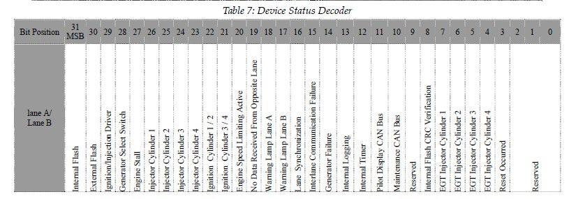
 The Rotax ECU transmits various status")

49 Page ROTAX 912IS Setup (MGL Avionics RDAC CAN required) The Rotax ECU transmits various status messages. These can be observed in the Engine, Sensor and Device status fields. Please see the 912IS installation and parameter settings in the installation section. When a MGL Avionics RDAC CAN unit is connected then the Xtreme-EMS will automatically rename AUX1/3 to COOLANT TEMP.
50 Page 50
51 Page GPS Setup GPS: Select OFF to disable the GPS information screen or select "EXTERNAL" if you have an external NMEA compatible GPS connected to the XTreme-EMS. If an external GPS is used then it must output the following NMEA sentences GGA - Global positioning system fix data RMC Recommended minimum specific GNSS data GSA GNSS DOP and active satellites GSV GNSS satellites in view NMEA stands for the National Marine Electronics Association. For more information please visit GPS BAUD RATE: Select the baud rate to match the external GPS receiver you are using. POSITION FORMAT: Select the display format of the GPS latitude and longitude. ALTITUDE UNIT: Select the unit of the altitude display. COG: Select if you want the COG to be related to true or magnetic north. LOCAL VARIATION: Select AUTO to allow the XTreme-EMS to automatically calculate the local variation or MANUAL for manual local variation input. AUTO LOCAL VARIATION: This item displays the calculated local magnetic variation. The XTreme-EMS will calculate the local variation every 10 minutes if a valid 2D or 3D GPS fix is obtained. MANUAL LOCAL VARIATION: This item allows the pilot to manually enter his local variation.
52 Page Timers Setup HOBBS MINIMUM RPM: Enter the RPM limit in which the Hobbs timer/maintenance timer must start incrementing. SET HOBBS TIME: This function allows you to set the engine Hobbs meter to any value. Typically, you would use this function to set the Hobbs meter to the current known engine time. Use the rotary control to change the value. Press the rotary control to accept and exit the menu option. If the Hobbs code is set to another value beside zero, then the pilot will be prompted to enter the Hobbs access code before allowing him to change the Hobbs time. This feature is useful for charted and flying school planes. CHANGE HOBBS CODE: This menu option allows you to change the Hobbs access code. You will first be prompted to enter the current code followed by entering in a new code followed by re-entering the new code. If the new code and the re-entered code is the same, then the Hobbs access code will be changed. Default code is 0000.

53 Page 53 SET MAINTENANCE TIMER: These timers allow you to keep track of engine maintenance interval. Set the timer when you have serviced your engine. A typical time might be 50 hours. This function allows you to set an engine maintenance timer. This timer is set in engine hours and it will count down to zero when the engine RPM is greater then the HOBBS MINIMUM RPM. A good use for this function is to set the hours until your next spark plug change or engine inspection. Use the rotary control to change the value. UTC OFFSET: Enter the UTC offset for your location. The UTC offset can be adjust in half an hour increments. RTC SOURCE: Select if you want the RTC UTC time to come from the GPS receiver or the internal RTC. Both real time clocks are powered by an internal 3V lithium coin cell battery. The internal battery can be replaced by unscrewing the 5 screws holding the back and front enclosures together as well as the 2 screws next to the D15 connector. Delicately slide out the electronics and replace the battery. The battery is a CR2032 coin cell. SET UTC DATE & TIME: Use the rotary control to set the UTC date & time in the internal RTC.
54 Page Data Recording Setup The XTreme-EMS has the ability to act as a black box recorder recording flight data directly onto an inserted SD card for later playback and investigation using the MGL Avionics Black Box viewer program. See the Black box viewer documents for further information. The Black box viewer can also convert the data into other file formats such as: KML: Keyhole Markup Language / Google Earth CSV: Comma-Separated Variable IGC: FAI Gliding commission The XTreme-EMS records the engine data as well as the GPS data (If an external GPS receiver is available) once per second WHEN A VALID FLIGHT IS DETECTED (AUTOMATIC OR MANUAL FLIGHT DETECT MODE). CREATE RECORDING FILE ON SD CARD: Selecting this menu option will create a file on the SD card (If inserted and not write protected) called enigma.rec with a fixed file size of 10MB. The reason behind the fixed file size of the recording file has to do with limited write cycles of the SD card and the instability of the MS-DOS file system. With a fixed file size, the XTreme-EMS never has to write to either the directory structure or FAT tables of the SD card eliminating wear of the card or possible data corruption. Once the recording file has been filled, the recording continues at the start of the file again, overwriting the oldest data in the file. The file size is large enough to record 5-20 hours of data depending on what data is recorded. DATA RECORDING ON: Selecting ON will enable the data recording functionality.


55 4.6.1 Examples of the exported flight data using CSV format and the KML format Page 55
56 Page Miscellaneous Setup AIRCRAFT REGISTRATION: Enter your aircraft registration. A maximum of 8 characters can be entered. The aircraft registration is displayed on the start up (Splash) screen. SAVE SETTINGS TO SD CARD: Select this option to save all the XTreme-EMS settings to the SD card. This is useful when setting up the instrument on the PC simulator and then later transferring the settings on the instrument itself. A file called XTREME.EMS will be created in the root directory of the SD card. This function is also used to save your settings during firmware upgrades. RECALL SETTINGS FROM SD CARD: Select this option to recall all the XTreme-EMS settings from the SD card. This is useful when setting up the instrument on the PC simulator and then later transferring the settings to the instrument itself. The settings will be loaded from a file called XTREME.EMS in the root directory of the SD card. This function is also used to recall your settings after a firmware upgrade. RDAC PROTOCOL: This option is only valid if using the optical RDAC interface, ignore this option if using the CAN interface. If using the RDAC-XF or RDAC-XF MAP RDAC and using the optical interface then set this menu option to extended otherwise set it to normal. Please note that the RDAC-XF dip switches must be SET to A=ON and B=ON for the extended messages to work. Please see the installation section for more information. It is recommended to use the CAN interface if using the RDAC-XF or RDAC-XF MAP
 Screen Creating your own Startup (Splash) Screen: You will need: A bitmap picture of your choice (*.")
57 Page ADC Values These values are mainly used for debugging purposes. Contact the MGL factory or your local dealer for more information. 5 Startup (Splash) Screen Creating your own Startup (Splash) Screen: You will need: A bitmap picture of your choice (*.BMP, 480x272 pixel resolution) The Enigma BMP to MIF converter tool (can be downloaded free of charge from or can be found on the XTreme SD card). The Enigma BMP to MIF program is used to convert images in Windows BMP format to Enigma MIF format. You can use this program to make your own startup screen (Splash screen) and graphic information display screens. The color depth is limited to Enigmas 256 colors. Run the Enigma BMP image to MIF format converter program. Load an image file (and remember the location), select the resolution as width(480) and height (272) and press the process button. The new MIF image will be located in the same directory as the source (BMP) file. If the original file was not named Splash.BMP, rename the new *.MIF file to Splash.MIF, and copy the Splash.MIF file into the root directory of your SD card. The picture will be displayed when the unit is powered up.
58 Page 58 6 Loading factory default settings Press and hold the left and right most soft keys simultaneously on power up to load default factory settings. The following message will be displayed: 7 Alarm condition If an alarm condition occurs the following will happen: The item causing the alarm condition will flash on the screen An alarm warning message will be displayed on the screen An external alarm switch will close The alarm warning message and switch closure will remain until any button is pressed or until the condition(s) that activated the alarm no longer exist. The alarm output can be used to switch an external alarm indicator. The external alarm switch is an open collector transistor switch to ground with a maximum rating of 0.5A DC. It is possible to wire the alarm contacts of several Stratomaster instruments in parallel should this be desired. To avoid false activation of the alarms, the alarm function is only active 10 seconds after the instrument has powered up. 8 Cleaning The unit should not be cleaned with any abrasive substances. The screen is very sensitive to certain cleaning materials and should only be cleaned using a clean, damp cloth. Warning: The XTreme-EMS is not waterproof. Serious damage could occur if the unit is exposed to water and/or spray jets.
59 9 XTreme-EMS Specifications Operating Temperature Range Storage Temperature Range Power Supply Current Consumption Power Consumption Display Display Backlight Dimensions ADC Enclosure Weight Alarm contact current rating Non-volatile memory storage Warm up time -10ºC to 50ºC (14ºF to 122ºF) -20ºC to 80ºC (-4ºF to 176ºF) 8 to 30Vdc SMPS (switch mode power supply) Built in 33V over voltage and reverse voltage protection Approx. 13.8V Approx. 1.8W x272 pixel active matrix TFT LCD 600 cd/m2 Sunlight Readable LED Front panel user adjustable Fits standard 3 1/8 instrument hole See section 12 for dimensional drawings 12 bits 100ksps Black ABS Front mounting Rear of enclosure fits a standard 3 1/8 instrument hole Approx. 250 grams (XTreme-EMS unit only) Open collector transistor switch to ground Maximum rating 0.5A DC write cycles 10 minutes Page 59


60 Page Installation 10.1 XTreme-EMS General Connection Diagram The use of an external 1A fuse is recommended. Connect the supply terminals to your aircraft s power supply. The XTreme-EMS can be used on both 12V and 24V without the use of any pre-regulators. Ensure that the supply voltage will not drop below 8V during operation as this may result in incorrect readings. Please see below for RDAC installation and usage.

61 Page XTreme-EMS DB15 Cable connections D15 Male DB 15 Pin Color Function 1 2 3,4,9, Red White Black NC NC NC NC Green NC NC NC NC 8-30Vdc power Alarm Output Ground RS232 Port 2 Transmit RS232 Port 2 Receive RS232 Port 1 Transmit RS232 Port 1 Receive OAT Probe CAN High CAN Low RDAC Signal Airtalk NC = Not Connected The XTreme-EMS has a D15 Female connector. The connecting cable must have a D15 male connector attached to it. The communication interface from your RDAC must be connected to either to the CAN bus or to the RDAC signal. See the installation section below for more details on the 2 communications interfaces and the different RDAC units.

62 Page MGL Avionics RDAC VD The RDAC model VD is an integrated, microprocessor controlled engine monitoring subsystem. It is intended for installation close to the engine, inside the engine compartment thereby eliminating the need for long probe and sender wires. If using the RDAC-VD then the RDAC protocol setting in the miscellaneous section must be set to normal The RDAC VD provides the following functions: 4 x EGT and/or CHT thermocouple inputs 2 x analog inputs intended for NTC type temperature senders 1 x oil temperature sender input (NTC or semiconductor types) 1 x oil pressure sender (resistive types) 2 x fuel level inputs (resistive types or active capacitive probes with low impedance voltage output from 0-2.5V) 1 x fuel flow sender input, can also be used to measure injector opening times on fuel injected engines to derive indirect fuel flow measurement. 1 x variable sensitivity RPM input The RDAC VD is intended for installation on all engines where up to four thermocouple senders are sufficient. For larger engines, please see the RDAC-XF and RDAC-XF MAP models. The RDAC VD is a good choice for engines such as most two stroke engines,rotax 912/914 engines and smaller two cylinder four stroke engines RDAC VD Power supply The RDAC VD requires supply from a 12V DC source. Voltages such as found in typical 12V nicad or lead-acid battery based installations are acceptable. The RDAC VD is designed to operate from 8VDC to 18VDC. Should your aircraft have a 24/28V system, you need to provide a 12V preregulator. In order to achieve maximum accuracy, it is important to route the power supply wiring correctly. It is important that the ground terminal connection is routed in as sort as possible manner to the engine block. The engine block must have a connection to the negative of the battery. Normally this connection is provided in the form of a heavy duty cable to allow for the considerable currents of an electric starter motor. Should your installation not have electric start, you will still need to provide this connection. Do not route the ground wire directly to the battery minus. This

63 Page 63 can lead to false readings on some senders. The ground wire must be routed to the engine block. You must have a connection from the engine block to the battery minus. The red wire must be connected to a +12V source RDAC VD function indicator The RDAC VD has a red LED that will flash in an approximate second interval if power has been supplied and the RDAC is functioning. Note: If you have not connected the ground terminal to the engine block and the engine block does not have a ground connection to the battery minus then the LED will not flash and your RDAC will not operate RDAC VD communications link The RDAC VD has a serial data communications link that is optically isolated, i.e. it has no electrical connection to the RDAC electronics itself. This prevents any form of electrical current flowing in this cable in case of an electrical wiring fault in your aircraft, in particular ground faults. There are three connections that are required to be connected: Braid Connect to the XTreme-EMS ground (D15 Pin 3,4,9,10) Blue (Data line) Connect to the blue wire of the Xtreme-EMS (D15 pin 14) Red Connect to the XTreme-EMS +12V power (D15 Pin 1).Used to power a pull-up resistor on the blue wire and provide the positive power connection to the RDAC
64 Page Installation of the RDAC VD The RDAC VD must be installed with the following requirements met: a) The RDAC must not be exposed to direct engine vibrations. Never mount the RDAC on the engine itself. Mount the RDAC on on the aircraft's firewall or similar suitable structure. b) The RDAC must be installed so extreme heat from the engine cannot damage it. c) The RDAC must be mounted in a position where it is protected from any engine oils or other engine fluids including water. d) If required the RDAC should be mounted inside a protected enclosure if it is otherwise not possible to protect it from environmental exposure such as rain. e) All wires to the baseboard must be secured such that it is not possible or any wire to be damaged due to chafing or that any wire can loosen itself from its connection terminal. f) If the RDAC is operated in conditions that may lead to corrosion of exposed electrical metal parts, suitable protection is a mandatory requirement. g) The RDAC includes very good protection against voltage transients on the power supply. However, in cases where severe transients containing a large amount of energy are expected, additional, external protection may be required. h) All signal connections that terminate in any of the RDAC terminals must never be allowed to contain dangerous high voltages such as can be created by ignition systems or inductive devices. In particular never route such cables alongside HT ignition leads.
.")
65 Page RDAC VD principle wiring diagram The following diagram shows a basic connection sample for various sensors. The actual connection of sensors depends on your application and setup in the display unit (instrument). Normally, in cases of multiple EGT/CHT thermocouple sensors, EGT sensors start from TC channel 1 while the CHT channels follow. The starting channel for CHT channels depends on your instruments setup. CHT1/H2O is used for either a NTC type water temperature sender or the 1 st CHT probe of a Rotax 912/914 engine. CHT2/ICE/FP is used for the 2nd CHT probe of a Rotax 912/914 engine.

66 Page RDAC VD thermocouple inputs Typical Thermocouple setup here Shown for four EGT probes. Please note that the probes are color coded. Yellow wires must connect to the + terminals and the red wires must connect to the - terminals. Thermocouple inputs details The RDAC VD EMS provides for up to 4 thermocouple inputs for use with EGT and CHT probes. Both K as well as J type probes can be used. K types are used for EGT probes while most CHT probes are also K types. Some makes of CHT probes are J type. Probe types are selected in the EGT SETUP and CHT SETUP menus of your XTreme-EMS. Important: Incorrect selection will lead to incorrect temperature display. The RDAC VD EMS will accept both grounded and isolated thermocouple probes. Your only consideration in case of the more common grounded configurations is that you need to ensure that the thermocouple mounting position (Exhaust flange, etc) is at the same electrical potential as the negative supply line of the RDAC VD (REF GND). RDAC VD thermocouple guidelines The thermocouple amplifier is a precision device providing full cold junction compensation and bow voltage correction. In addition the amplifier measures and corrects for its own errors. This results in very accurate measurements providing you install high quality probes. Here are some guidelines: EGT Probes: Select probes that are made from 316 stainless steel and that use glass-fiber insulated conductors. Teflon insulated conductors as found in many cheap probes introduce errors as the insulation melts moving the measuring point towards the mounting bolt which transfers a lot of heat to the exhaust material. This results in under reading probes. Stay away from probes that use simple plastic heat shrink sleeving it does not last. Choose probes that use a generous amount of stainless steel spring as strain relief. The Bolt itself should be stainless as well or it will rust very quickly.
67 Page 67 CHT probes: These are made from washers to fit spark-plug bases. Temperatures are considerably lower so most thermocouple cables will work without problems. The biggest area of concern should be the connection of the thermocouple cable to the washer. This often breaks after the spark plug has been changed a few times. Choose a probe that is suitably reinforced at this point for a long and trouble free life. EGT and CHT probes supplied by MGL Avionics are of highest quality. We recommend that you consider using our probes if at all possible. Warning: Four stroke engines produce much hotter exhaust gases compared to two stroke engines. Do not use EGT probes made from lower grade stainless steel (for example 310), these probes will not withstand the high temperatures and can fail as the metal gets very soft at 800 degrees C. Many four strokes (such as the Rotax 912) will produce exhaust gases of up to 850 degrees C. Important installation note: EGT and CHT probes use wire made from plain Iron and other basic metals. As a result these probes are not able to withstand much flexing of the wires due to engine vibrations. Avoid making nice looking coils or similar constructions that will result in excessive vibration or flexing of the wire. Route the cables from the probe points tightly along suitable engine mounting points eliminating any chance of unnecessary wire flexing during engine operation.

68 Page RDAC VD Connecting coolant temperature, oil temperature and oil pressure senders. This drawings shows the connection of a coolant temperature probe, a oil temperature probe and a oil pressure sender. Note that all of these probes require a good electrical ground connection to the engine block so they should never be installed using sealant or PTFE sealant tapes. The RDAC VD REF GND connection should also be wired to the engine block. The RDAC VD supports various types of temperature senders and well as oil pressure senders. These are selected in the relevant setup menus of your instrument. Please note that the CHT1 and CHT2 terminals are used in case of a Rotax 912 or 914 engine to interface to the two built in CHT senders. These senders are standard VDO oil temperature senders. Coolant and oil temperature senders are mostly NTC resistors. These are resistors that vary their resistance with temperature. These senders come in a wide variety so ensure that the sender you are using is compatible with the instrument and that you have selected the correct probe type in the relevant setup menu.

69 Page RDAC VD Fuel flow sender installation Note: Direction of fuel flow Indicated by arrow on sender RED wire Fuel Flow Sender Supply BLUE wire Fuel Flow Sender signal Braid Fuel Flow Sender Ground Warning: Incorrect wiring can damage both the RDAC unit as well as the flow sender. The optional Fuel Flow Sender is highly recommended for use with Xtreme-EMS. It provides instantaneous readouts of hourly fuel usage, and both time and distance estimates on remaining fuel in flight. You can also verify the performance of your fuel pump during the pre-takeoff engine run up a very valuable check! Further, it is possible to set up the instruments to calculate Fuel remaining by subtracting fuel used from a value entered when you filled your tank(s). In this case you may omit the installation of the optional fuel level sender. Please note that the installation of the Fuel Flow sender should be done in such a fashion that dirt or debris from the fuel tank cannot lodge inside the flow sender. These will not block you fuel flow but may lead to the impeller inside the sender jamming. It is usually sufficient to mount the Flow sender AFTER the fuel filter but before the fuel pump. It is a good idea to provide a small reservoir such as a primer bulb between the flow sender and the fuel pump.
70 Page 70 As indicated in the recommended fuel flow sender installation drawing, it can be of advantage to install the flow sender in such a fashion that the inlet points slightly down and the outlet points slightly up. This prevents vapor from forming a bubble inside the flow sender. We strongly recommend to mount the flow sender in such a fashion that the impeller rests on only one bearing. This is achieved if you mount the sender such that the surface with the arrow faces upwards. Mounting the sender like this results in the best performance at low flow rates as only very little friction is present. The flow sender is delivered with a small jet that can be installed in the flow sender inlet. Installation of this jet is recommended for engines with fuel flow rates lower than about 30 liters per hour. This would apply to most small two and four stroke engines. The Xtreme-EMS is shipped with the Fuel sender calibration set for the jet installed. In a good installation you can expect about +/- 3% maximum flow reading error with this factor. You can calibrate the flow sender yourself to a higher degree of accuracy if you so desire. Recommended procedure to calibrate the fuel flow sender: Note: You must disable the Fuel Level sender if you have one installed first. Fill your tank exactly to a known level (for example 50 liters). Set your fuel level to 50 liters using the Main Menu. If required you may have to disable the fuel level sender. Fly your aircraft for a period that you know will use approximately 20 liters of fuel. The exact fuel burn is not important, just burn about 20 liters of your fuel. At the end of your flight the Xtreme-EMS should give you a reading of how much fuel you have left the reading should be about 30 liters left. Now place your aircraft in exactly the same position that you used when you first filled the tank and refill the tank to 50 liters using a measuring jug. You should find that you need 20 liters of fuel to refill to 50 liters. If you find that the instrument under or over reads the fuel used, you should perform a simple adjustment of the Fuel Flow sender calibration factor. Example: Actual fuel used: 21.5 liters, Xtreme-EMS fuel burn calculated 29.7 liters left in tank. This means the Xtreme-EMS measured = 20.3 liters. We are under reading by 1.2 liters. Default Kfactor Fuel menu =7000. Let the corrected calibration factor be X. X = (21.5 * 7000) / 20.3 X = The closest setting you can enter as factor is Enter it into the unit and you are done! Repeat the above procedure to verify that your flow sender is now reading correctly.
71 Page 71 Please note: Before you calibrate the flow sender ensure there are no problems with your installation. We find the senders are very accurate if everything is installed and working properly. If your fuel burn indication is out by a large amount you have a problem that you should not attempt to fix by fiddling with the calibration factor! Please ensure that no fuel vapor can be trapped inside the sender housing in the form of bubbles. Due to the low fuel flow rates the bubbles will prevent the tiny impeller from turning freely, You can verify the turning of the impeller. You should notice three dark spots that are just visible in the inside of the fuel flow sender. These are small magnets that are attached to the impeller. With fuel flowing you should see the magnets turning. The best defense against vapor bubbles is to install the flow sender in such a way that the bubbles can escape. The easiest way is to point the outlet slightly upwards and the inlet (with the jet) slightly downwards. Another possible problem is the fuel sender jet. When you install it, do not damage it. Use a drill bit of suitable diameter to push the jet all the way the opening of the jet must be just in front of the impeller. YOU NEED TO APPLY SOME FORCE TO INSERT THE JET ALL THE WAY. THE JET MUST BE LOCATED RIGHT IN FRONT OF THE IMPELLOR. YOU CANNOT PUSH THE JET TOO FAR. Using other Flow Senders It is quite possible to use Flow Senders other than the MGL Avionics device. In this case ensure that the Sender outputs a 5V TTL square wave or a similar signal. The RDAC interface electronics will adapt to a variety of different voltages and pulse shapes as it contains a schmitt-trigger input stage. The calibration factor can be entered in a wide range making the unit particularly suited to other Flow senders. The supply output terminal for the Sender provides a positive, regulated 5 volt output. This may be used to power the Flow Sender provided the Sender will not draw more than 40 ma of current. Should your sender require a higher voltage or more current, then you must supply the sender from a different power source. Exceeding the rating on the Stratomaster Flow sender supply terminal can affect the operation on the unit negatively or even damage it. Recommended Calibration Factors for the MGL Avionics dual range flow sender: With jet installed = Recommended with flow rates below 30 liters/hour maximum. Without jet installed = Recommended with flow rates above 30 liters/hour. Please refer to the leaflet included with the Flow Sender for information on pressure drop vs. flow rate, wetted materials etc. It is your responsibility to ensure that the flow sender used is compatible with the fuels you intend using. We have found the MGL Avionics sender to be very compatible with automotive fuels used in South Africa, many of which contain methanol. 100LL AVGAS also appears not to harm the sender in any way. We have exposed a sender continuously to our automotive fuels for a duration of two years without any noticeable ill effect on the sender. However, despite this MGL Avionics or its appointed agents cannot assume responsibility for any incident or damage, even loss of life by whatsoever cause connected with the fuel flow sender or the Stratomaster Flight Instrument. Usage of this or other senders is your own sole responsibility. If you do not agree with the above statement you must not use the fuel flow sender. Note to Pilots: You must always have a visual indication of the fuel level available, either by means of a sight glass, direct tank observation or a known, reliable secondary fuel level gauge. Fuel level indication by means of calculated fuel burn is subject to errors both by entering incorrect starting fuel levels as well as mechanical problems causing the flow sender impeller to turn too slowly, resulting in under reading fuel burn and thus over reading remaining fuel. As pilot in command of an aircraft it is your responsibility to ensure that you have sufficient fuel to reach your intended destination. Always ensure that you have a generous amount of reserve fuel and never use your reserve fuel except in an emergency if it is unavoidable.
. After you have connected the system as shown above you can proceed to set up the system.")
72 Page RDAC VD Fuel injection system monitoring Should you want to monitor fuel flow directly by means of measuring the fuel injector opening time, the above arrangement can be used. You can use both high or low fired injectors (most systems are low side fired as shown above). After you have connected the system as shown above you can proceed to set up the system. (don t forget that you need a connection from the RDAC ground terminal to the engine block (at the same potential as the battery negative). a) Select INJECTOR for MODE in the fuel setup menu. b) Select high or low side fired injector (INJECTOR: HIGH or LOW). c) Select a suitable K-Factor to give you correct rate of flow. A good starting value may be in the range. Increase to lower indicated flow and decrease to have a larger indicated flow. Flow through the injectors may not be 100% linear with switching times due to various effects. However, it is possible to obtain very good performance from this flow monitoring system if you keep the following in mind: Calibrate the K-Factor so flow indication is accurate during cruise, the period your engine spends most of its active time at. Ensure that you have a correctly working fuel pressure regulator. The more constant your fuel pressure, the more accurate the flow indication. Never use this or any other flow system as your only fuel level indication. This is not the intended purpose of a flow measuring system and this can be dangerous if for whatever reason incorrect flow is indicated.

73 Page RDAC VD Connecting fuel level sender(s) The RDAC VD EMS permits the connection of one or two standard automotive fuel level senders. These senders can be obtained at automotive spares outlets at reasonable cost. When you choose a float level sender, ensure that you select a model that is sturdy and promises reliable and long lifetime. In particular, select a model that does not have any metal parts that can rust. The RDAC VD EMS can interface to a large variety of these fuel level senders. It does not matter if the sender resistance increases or decreases with the fuel level as long as it changes. The calibration procedure outlined in the fuel setup menu describes in great detail the procedure to follow. In essence, the calibration procedure will measure the resistance of the fuel level sender at various fuel levels and then work out the readings in between those known settings. Typical fuel level senders that can be used with the RDAC VD EMS have resistance ranges in the region of 100 ohms to 500 ohms. You can connect capacitive senders as well. These generally come in two types: The first emulates a normal resistive probe and is simple to connect and use as a result. The second type has a voltage level output. These can be used if the voltage can be set to a range of about 0-2.5V. Higher voltage levels will result in the instrument assuming a problem. The RDAC VD supports one or two fuel tank level senders. You need to enable these in the tank 1 and tank 2 setup menus. Safety Hazard! Please read this: Be careful when installing fuel level senders into fuel tanks. Ensure that the fuel tank is completely empty when you proceed with the installation. Ensure that the fuel tank is well ventilated and does not contain any fuel vapors these are highly explosive when mixed with air.ensure that at all times the ground connection (the connection of the fuel level sender mounting flange) is securely connected to the aircraft frame (in case of a metal frame) and to the negative terminal of the battery. In addition the negative terminal of the battery must at all times be connected to the Supply ground terminal of the RDAC VD EMS. Please note this wiring is critical and must never break in flight. It would be possible to create electrical sparks in the fuel tank if your wiring is faulty or incorrect. The consequences of this can be imagined. This has nothing to do with the RDAC EMS itself but is a general hazard for any automotive fuel level sender installation. If you have no experience with electrical wiring, PLEASE delegate the task to a qualified automobile electrician or electronics technician. If you need to remove the RDAC VD EMS, please first disconnect and secure the fuel level sender wire before disconnecting anything else.


74 Page RDAC VD Connecting the rev counter Adjusting rev counter sensitivity The rev counter has a sensitivity adjustment trimmer as shown in the picture below. Adjust this trimmer using a small screwdriver such that you get stable RPM readings over the entire rev band of your engine. If your sensitivity is too high, you may get unstable RPM readings (usually at higher RPM as electrical noise in the ignition system increases). If the sensitivity is too low the RPM reading may remain at zero. Magneto systems such as found on Jabiru and similar engines. After you have connected the rev counter terminal to the signal source you need to set the number of pulses/rev in the RPM setup menu. The calibration itself depends on your engine type and what kind of signal you are using. Typical sources are: Magneto coils (suitable signal at the kill switch). Primary (low voltage) side of ignition coil, at contact breaker or electronic ignition module. RPM counter output of electronic ignition systems (for example Bosh Motronic). RPM pickup devices such as hall-effect sensors on flywheels etc. Typical calibration settings are 10 or 20 for most engines.
75 Page 75 The rev counter input on the RDAC can be used with signals from about 5Vpp to as much as 100Vpp. A noise filter is included that results in the input ignoring any noise signals as long as this is below the detection threshold of about 2.5Vpp. The input impedance of the rev counter input is approximately 10Kohm. You can use series resistors as well as load resistors for applications that have unusual signals. Rev counter pickup from automotive engines

76 Page 76 Connecting the rev counter on a two stroke Rotax Such a system produces 6 pulses for every revolution of the engine. Other engines can be used but you must adjust the pulses/rev setting accordingly For example: Rotax 503 or Rotax 582: 6.0 pulses/rev Rotax 912 or Rotax pulses/rev The rev counter input can be connected to a variety of different sources such as the low voltage side of a ignition coil (at the points contact breaker) or to rev counter outputs of fuel injection computers. Note: Some Rotax engines may require that a 220 ohm ballast resistor is fitted between the rev counter input and the REF GND terminal. This resistor should be fitted if you cannot obtain stable RPM throughout the range regardless of any setting of the rev counter sensitivity adjustment.

77 Page 77 Connecting the rev counter to a Rotax 912 engine The Rotax 912/914 contains two built in NTC type CHT temperature senders. In addition oil temperature and oil pressure sender is provided as standard. Due to the fact that the 912 has two carburetors (one for each side of the engine), two EGT probes should be connected, one for each exhaust stack. You can connect four EGT probes if you like. You would use TC1 and 3 as one pair and TC2 and 4 as the other pair. Each pair monitors one side of the engine. CHT1 and CHT2 connect to the standard CHT senders, again one for each side. Connect oil pressure and oil temperature and you are done. Connect the Rev counter wires (blue/yellow and white/yellow) as follows: One of the two wires needs to be connected to ground (engine block), the other to the REV counter input. Do not forget to set the pulse per rev to 1.0 as the engine generates one pulse for every revolution. Please note: Most of the senders are grounded configurations This means they connect electrically to the engine block. It is vital for good and stable readings that you connect the Ground terminal of the RDAC to the engine block using a short, good quality electrical connection. Never use sealant or PTFE tape on the threads of the senders. This may electrically isolate the senders which will result in incorrect indications. The threads on these senders are expanding threads which are designed to create a tight metal to metal seal.

78 Page 78 Connecting a Rotax 503 or 582 This diagram shows EGT, CHT and water temperature sender locations and wiring based on a Rotax 582. This is a water cooled engine so CHT senders should be viewed as optional. For a Rotax 503 or similar air cooled installation, proceed similar but omit the water temperature sender and wiring. Please note that the ground connection (black wire) from the RDAC must be connected to the engine block as shown. Select a suitable point on your engine block for this connection. The engine block itself needs to be connected to the negative supply, in all cases this should be a direct connection to your batteries minus terminal. This should be a thick copper cable with a very low resistance and it needs to be as short as possible. This requirement is even more severe if you are using electric start as the very considerable currents required by the starter motor will be using this connection.

79 Page 79 Connecting a Bendix magneto as RPM source The above drawing shows the connection required if you would like to connect a magneto as RPM source. Shown is a typical Bendix magneto as used on Lycoming and other aircraft engines. You should find a wire connected to a terminal on the magneto that originates from your magento kill switch (or starter switch). The terminal is often refered to as a P-terminal. Connect a wire as shown and connect this to the Rec counter input of the RDAC. We strongly recommend that a resistor is inserted into your wire as shown. A good value would be ohms (10K). A normal 1/4 W resistor is just fine. The above circuit can also be used on other magneto systems such as found on Jabiru and similar engines.

80 Page MGL Avionics RDAC XF and RDAC XF MAP RDAC XF MAP version has a map sensor fitted. Input Connections TC1 to 12 GND OIL P OIL T Fuel P Cool Curr FL 1 FL 2 AUX 1 & AUX 2 RPM 1 RPM 2 5V Out FF 1 FF 2 MAP Sensor Inputs for use with thermocouple temperature probes. Typically used for EGT probes (K-types) and CHT probes (K or J types). Can also be used for other types of temperature monitoring depending on abilities of connected system. Grounding point. Connected to the engine block, also used as ground for sensors not electrically connected to the engine itself such as flow senders and current senders. Oil pressure sender Oil temperature sender Fuel pressure sender Coolant temperature Electrical curent sender (E.G. MGL magnetic current sender) Fuel level sender for tank 1 Fuel level sender for tank 2 Auxiliary inputs. Used for example for Rotax 912/914 NTC type CHT probes Engine RPM input 1 Rotor RPM input 2 5V DC supply output intended only for low current users (30mA maximum). Typically used as supply point for MGL fuel flow Fuel flow sender 1 Fuel flow sender 2 This 1/8 NPT fitting connects to an internal MAP pressure sensor. (Range: Bar). Optional, fitted to RDAC XF MAP
81 Page 81 D9 Pin Name Function OPTTX RX OPT+ GND CAN+ CANVIN 9 GND No Connect No Connect No Connect No Connect Ground. Connect this to engine block (and engine block to battery negative). Do not connect directly to battery negative. This must be routed via the engine block. CANH signal line to XTreme-EMS CAN H (D15 Pin 12) CANL signal line to XTreme-EMS CAN L (D15 Pin 13) +12V supply from battery via power switch / circuit breaker and fuse if required. Ground. Connect this to engine block (and engine block to battery negative). Do not connect directly to battery negative. This must be routed via the engine block. This terminal may be left unconnected if desired, it is connected to pin 5 internally RDAC XF Dip Switches Off Position On Position Dip Switch Function RDAC SEL B & RDAC SEL A AUX 1 PU AUX 2 PU OIPP PD OIPP PU Fuel P PU Coolant PU Fuel level 2 PU Fuel level 1 PU RPM 2 Filter RPM 2 Ballast These switches are used to assign each RDAC in the system with an ID number. Set both switches to the off position. used to pull the AUX 1 sensing line high used to pull the AUX 2 sensing line high used to pull the OILP line low used to pull the OILP line high used to pull the Fuel Pressure sensing line high used to pull the Coolant sensing line high used to pull the Fuel level 2 sensing line high used to pull the Fuel level 1 sensing line high Adds a high frequency filter to the signal path used when the RPM 2 signal line requires a 220 ohm ballast resister to ground used when the RPM 2 signal needs a High Gain (increases signal sensitivity approximately by a factor 10) Adds a high frequency filter to the signal path used when the RPM 1 signal line requires a 220 ohm ballast resister to ground used when the RPM 1 signal needs a High Gain (increases signal sensitivity approximately by a factor 10) RPM 2 High Gain RPM 1 Filter RPM 1 Ballast RPM 1 High Gain PD = pull down resister PU = pull up resister
 line if required. Please check the senders information for type and settings needed.")
82 Page 82 This drawing illustrates the pull up resister circuit This drawing illustrates the pull up and pull down resister circuit for the oil pressure These circuits shows how the various PU switches feeds 5 volt onto the input(sense) line if required. Please check the senders information for type and settings needed. The 2nd circuit shows a pull down circuit that has a 100Ω load resister switched to GND. This intended for use with the Rotax 4-20 ma oil pressure sender. The white wire is connected to the OILP input on the RDAC XF. The OILP PD switch must be in the ON position and the OIL PU switch must be in the OFF position. Passive senders such as resistive temperature and pressure senders will require the pullup resistor to be ON. If you are using active senders (mostly used as electronic pressure senders) please switch the pull-up resistor OFF. Default settings for most installations (assuming the Rotax 4-20mA sender is not used):

83 Page RDAC XF Sensitivity gain adjust RPM 1 MIN MAX Adjusts sensitivity of the RPM1 input RPM 2 MIN MAX Adjusts sensitivity of the RPM2 input Sensitivity to input signals on the RPM inputs can be adjusted over a wide two switchable ranges (via the DIPSwitch selection, high and low range). Highest sensitivity achievable is around 0.4V peak to peak in high gain and 4V peak to peak in low gain. From this level, the trimmers can be used to reduce the gain over a very wide range to around 50V peak to peak or higher depending on trimmer setting RDAC XF Indicator The green LED flashes at about 1Hz during operation. If the LED is steady ON there is a serious fault with the RDAC and it cannot operate. If the LED is OFF the RDAC is not being supplied with power or there is a serious fault with the RDAC RDAC XF Installation Precautions Note that the unit is not waterproof, when installing the unit in a location where it will be exposed to fluids it is advisable to install it in an enclosure(box) This unit is intended for mounting on the aircraft's fire-wall,engine side. The unit is not designed for mounting directly to the engine! Excessive vibration, moisture and temperature extremes will damage the RDAC or shorten its life span. Advisory! Once installation is complete and all setups regarding RDAC XF are done, it is important for the dip switches and sensitivity gain adjustment to be covered (Suggestion: clear self adhesive film). This is to prevent dust and moisture getting in to the switches, variable resisters and other components.
84 Page RDAC XF Dimensions RDAC XF Wiring It is important to connect the RDAC ground wire to the engine block. Failure to do so will result in the readings from the engine sensors to be incorrect. Please note that the following steps need to be done correctly otherwise unit may function incorrectly or damage could result from bad installation. Take care to insulate all exposed connections. Plan your wire routings carefully to minimise chaffing of cables. The engine compartment may get hot so use suitable wire. Make neat connections with minimal exposed wire showing from connectors. If you are not sure, then ask for advise from an AMO Connecting the RDAC-XF to the XTreme-EMS Observe the polarity of the two CAN wires. One of the lines is called CAN L and the other CAN H. It is recommended that a twisted pair wire is used for this connection using two wire colors for ease of identification. The CAN bus must be terminated at each end with a 120 ohm resistor. Connections from equipment into the CAN bus (other than the ends) must only use short stubs into the bus (maximum length of a stub should not exceed 20cm if possible). It is OK to use only a single resistor of value ohms if the total length of the CAN bus is not more than two meters (6 feet).
85 Page RDAC XF Thermocouple Probes Inputs (EGT/CHT) TC 1 to 12 provide up to 12 channels for thermocouple temperature sensors. You can use K TYPE thermocouple probes for EGT and K or J TYPE thermocouple probes as CHT sensors. Note that you need to setup the XTreme-EMS so it knows the probe types and what channels you are using. The TC setups on the Xtreme-EMS are programmed to see the first TC inputs as EGTs then followed immediately by CHTs. Example: 2 EGTs and 4 CHTs then TC1=EGT1, TC2=EGT2, TC3=CHT1, TC4= CHT2, TC5=CHT3 and TC6=CHT4. These are some examples of J and K type thermocouple lead colour codes and corresponding polarity
86 Page 86 RDAX XF thermocouple guidelines The thermocouple amplifier is a precision device providing full cold junction compensation and bow voltage correction. In addition the amplifier measures and corrects for its own errors. This results in very accurate measurements providing you install high quality probes. Here are some guidelines: EGT Probes: select probes that are made from 316 stainless steel and that use glass-fiber insulated conductors. Teflon insulated conductors as found in many cheap probes introduce errors as the insulation melts moving the measuring point towards the mounting bolt which transfers a lot of heat to the exhaust material. This results in under reading probes. Stay away from probes that use simple plastic heat shrink sleeving it does not last. Choose probes that use a generous amount of stainless steel spring as strain relief. The Bolt itself should be stainless as well or it will rust very quickly. CHT probes: These are made from washers to fit spark-plug bases. Temperatures are considerably lower so most thermocouple cables will work without problems. The biggest area of concern should be the connection of the thermocouple cable to the washer. This often breaks after the spark plug has been changed a few times. Choose a probe that is suitably reinforced at this point for a long and trouble free life. EGT and CHT probes supplied by MGL Avionics are of highest quality. We recommend that you consider using our probes if at all possible. Warning: Four stroke engines produce much hotter exhaust gases compared to two stroke engines. Do not use EGT probes made from lower grade stainless steel (for example 310), these probes will not withstand the high temperatures and can fail as the metal gets very soft at 800 degrees C. Many four strokes (such as the Rotax 912) will produce exhaust gases of up to 850 degrees C. Important installation note: EGT and CHT probes use wire made from plain Iron and other basic metals. As a result these probes are not able to withstand much flexing of the wires due to engine vibrations. Avoid making nice looking coils or similar constructions that will result in excessive vibration or flexing of the wire. Route the cables from the probe points tightly along suitable engine mounting points eliminating any chance of unnecessary wire flexing during engine operation.

87 Page RDAC XF Oil, Fuel Pressure and Coolant monitoring Oil P connect to oil pressure sender OIL T connect to oil temperature sender FUEL P connect to fuel pressure sender COOL connect to water temperature sender It is important to know what type, range and connections are needed for the sensors. In the EFIS and I-EFIS units menu's relating to the sensors placement can show you what sensor types can be used. Most sensor types are resistive. In this case you have a pull-up resistor enabled via the DIPSWITCH array. The pull-up resistor connects to 5V DC internally. The sensors resistance forms a resistive voltage divider to ground. The resultant voltage on the sensor is measured and translated into a sensor reading depending on the type of sensor connected. Electronic pressure senders tend to output a voltage level in proportion to applied pressure. For these devices it is recommended to switch the pull-up resistor off. Rotax 4-20 ma oil pressure sender part no The sensor cable is approx. 3 m long and has 3 leads. The Black lead is not to be connected and has no function. The Red lead from the sensor has to be connected to the positive bus via a fuse or circuit breaker The White lead (output signal) has to be connected directly to the OILP input on the RDAC XF. The OILP PD switch must be in the on position and the OILP PU switch must be in the off position. This sets up the RDAC XF to measure the current injected into the grounded 100 ohm resistor.
88 Page RDAC XF Current Input CURR connect to MGL Current Sensor or any other electronic current sensor that provides an output centered around 2.5V for zero current.this example shows connection of the MGL Magnetic current sensor. Connect sensor wires as indicated. Connect the current sensor power (red wire) to the RDAC positive supply and the black wire to GND. The magnetic current sensor can be installed in several ways depending on the current range it is to measure. Please refer to the documentation for this sensor.
89 Page RDAC XF Fuel Level Inputs FL 1 connects to fuel level sender output/signal from tank1 FL 2 connects to fuel level sender output/signal from tank 2 ( if installed) Safety Hazard! Please read this: Be careful when installing fuel level senders into fuel tanks. Ensure that the fuel tank is completely empty when you proceed with the installation. Ensure that the fuel tank is well ventilated and does not contain any fuel vapors these are highly explosive when mixed with air. Ensure that at all times the ground connection (the connection of the fuel level sender mounting flange) is securely connected to the aircraft frame (in case of a metal frame) and to the negative terminal of the battery. In addition the negative terminal of the battery must at all times be connected to the Supply ground terminal of the RDAC X EMS. Please note this wiring is critical and must never break in flight. It would be possible to create electrical sparks in the fuel tank if your wiring is faulty or incorrect. The consequences of this can be imagined. This has nothing to do with the RDAC EMS itself but is a general hazard for any automotive fuel level sender installation. If you have no experience with electrical wiring, PLEASE delegate the task to a qualified automobile electrician or electronics technician. If you need to remove the RDAC X EMS, please first disconnect and secure the fuel level sender wire before disconnecting anything else.
90 RDAC XF Aux Inputs AUX 1 is an axillary input for extra temperature sensors( cht1,coolant) AUX 2 is an axillary input for extra temperature sensors (cht2) The AUX inputs can be used to measure temperature or pressure with the use of a variable resistance NTC type probes. Electronic sensors such as the popular type LM335 can also be used. This is a typical Rotax 912/914 CHT sensor connection. With this setup the AUX 1 PU and AUX 2 PU switches will be in the ON position. Page 90
91 Page RDAC XF Rpm Inputs RPM 1 This input connects to one of your magneto, ignition, ecu or pick-up units RPM 2 This input connects to a rotor rpm feed. (auto gyro or helicopters). On the XTreme-EMS the RPM generally works by taking the highest RPM reading for display on the standard screens. This drawing of a system that uses a pick-up sensor (Hall Effect Sensor) sometimes seen on Rotax engines. Each RPM input has the following options: Noise filter: This can be switched into the signal path to help in removing high frequency noise from the signal that can result in unstable readings. Use this switch only if you rely on a dirty signal. An example of such a signal is a direct coupling to a magneto device. Ballast resistor: This switches a 220 ohm ballast resistor to ground. This can be used to reduce noise or secondary pulses on the RPM line. Often used with Rotax engines. Note: For direct magneto pickups this switch must be OFF as otherwise the magneto pulse may have low energy in particular at idle. Gain setting: Switch on selects a high gain. In this case the input is about 10 times more sensitive than normal. Used only for low level signals such as inductive pickup coils.

 0.")
 RPM 1 High Gain on 0.")
 RPM 1 High Gain turned ON ECU units may have a")
92 Page 92 RPM 1 shows ¼ turn RPM 1 shows mid position RPM 1 shows max position RPM 1 High Gain on 3.5V (Peak to Peak) RPM 1 High Gain Off 35V (Peak to Peak) 0.8V (Peak to Peak) RPM 1 High gain on RPM 1 High Gain off 8V (Peak to Peak) RPM 1 High Gain on 0.4V (Peak to Peak) RPM 1 High Gain off 4V (Peak to Peak) RPM 1 High Gain turned ON ECU units may have a digital RPM output you may be able to use. RPM 1 High Gain turned OFF
93 Page 93 This a drawing of a magneto system. In this case the RPM feeds are taken from the P connection terminal. Note that the two magnetos are connected to the appropriate RPM inputs with a recommended 10KΩ ( ohms) resister in line. In this case you would have the RPM 1&2 BALLAST switches in the OFF position.
94 Page 94
95 Page RDAC XF Fuel Flow Inputs This example is based on typical MGL flow senders: FF1 & FF2 Connection of fuel flow sender (Braid to GND, Red to +5 volts, Blue to FF1) If a second fuel flow sensor is used then the braid and red wires of the second flow sender connect as the first sender but the blue wire (signal) connects to FF2. Using the Fuel Flow Sender It is important to install the fuel flow sender at an angle so that will no bubbles can get trapped in the impeller section. This will cause incorrect or erratic readings. It is also important to work out what fuel flow to expect (generally manufacturers specify fuel usage per hour) in order to select the right jet for the fuel flow sender unit. Please note that the installation of the Fuel Flow sender should be done in such a fashion that dirt or debris from the fuel tank cannot lodge inside the flow sender. These will not block your fuel flow but may lead to the impeller inside the sender jamming. It is usually sufficient to mount the Flow sender AFTER the fuel filter but before the fuel pump. It is a good idea to provide a small reservoir such as a primer bulb between the flow sender and the fuel pump. Using Injectors In this injector system is the injector has a +12volts connection but the negative (low) side of the injector is switched/fired by the electronic injector control system. For this reason in Fuel related setup; Fuel flow setup menu the selection should show as Flow sender type Rdac one: InjectorL Most systems used are low triggering/firing systems If a positive(high) switching/ firing injector system is used then the selection will show Flow sender type Rdac one: InjectorH
96 Page RDAC XF Manifold Air Pressure Input Please note that the MAP Sensor is only available on the RDAC XF MAP The MAP Sensor is connected to the manifold. This sensor measures the air pressure or vacuum in the manifold. In the case of the 912 and 914 Rotax engines there is a pipe connecting the two manifolds where this connection can be made. On the RDAC there is a standard 1/8th NPT female threaded fitting.
97 RDAC XF Temperature monitoring connection for Rotax RDAC XF typical sensor connection layout Page 97


98 Page MGL Avionics RDAC CAN RDAC CAN General The RDAC CAN interface forms the bridge between the Rotax 912iS ECU and the XTreme-EMS. The RDAC CAN interface provides the following: - Interface to Rotax ECU Lane A with fallback to Lane B on Lane A failure. - 2 fuel level sender inputs with internal pullups suitable for resistive senders. Pullup resistors can be disabled allowing senders with a voltage output to be connected. - Fuel pressure input suitable for use with a voltage output electronic sender. - Input for a DC current monitor centered around 2.5V (range V). The RDAC CAN emulates the RDAC XF system RDAC CAN Data Connections:
99 Page 99 As shown on this diagram, connect the CAN bus ECU lanes A and B together and then connect to the RDAC CAN CAN ECU inputs. Do NOT add CAN termination resistors to this connection as both ECUs have these built in. Connect the RDAC CAN to the CAN interface of the XTreme-EMS. Observe CAN bus termination resistor recommendations for this connection RDAC CAN Rotax 912iS XTreme-EMS Setup The Xtreme-EMS must be setup as follows: RPM: PULSES/REV: 1.0 Fuel Flow: K-FACTOR 1: 3500 MODE: FLOW SENDER Manifold Air Pressure: No change needed Oil Pressure: TYPE: 0-5V SENDER: User CALIBRATE SENDER: POINTS: 2 DISPLAY 1: 0.0 bar ADC 1: 0000 DISPLAY 2: 10.0 bar ADC 2: 4095 Oil Temperature: SENDER: LM335 LM335: 0 Coolant Temperature: This is remapped to ANALOG AUX1/3 FUNCTION: TEMPERATURE SENDER: LM335 LM335: 0 LABEL: COOLANT EGT 1,2,3,4 EGT CHANNELS: 4 Throttle Position: 0-100% can be viewed in the ROTAX 912iS section Engine Ambient Pressure: This can be viewed in the ROTAX 912iS section Fuel Level senders: This is setup as normal in the fuel setup menu Fuel pressure sender: This is setup as normal in the fuel setup menu
100 Page 100 DC current input: This is setup as normal in the current setup menu Functions provided by the RDAC CAN The RDAC CAN provides a number of additional sensor monitoring inputs on the D25 connector. Fuel level sender inputs These inputs are marked FL1 and FL2. These are intended for connection to resistive fuel level senders. The RDAC CAN provides internal pullup resistors (470 ohms to 3.6V). These pullup resistors are switched into the circuit if the internal DIP switch array 7 and 8 are in the ON position. If the switches are OFF it is possible to connect electronic level senders with a voltage output provided the output voltage is in the range of 0V to about 3.3V. The fuel level sender readings are presented to the EFIS in a fashion compatible with the RDAC XF. Fuel pressure sender input Use input Curr1 to connect to a 0-5V or V DC output fuel pressure sender. Select the corresponding sender type in the Xtreme-EMS fuel pressure configuration menu. It is also possible to use a resistive pressure sender. In this case connect the pressure sender to the fuel pressure sender input (the other end of the fuel pressure sender variable resistor is connected to ground via the engine block). Also connect a pull-up resistor of 2.7KOhms from the fuel pressure input to the 12V supply this will energize a typical 200 ohm VDO sender. DC current monitoring input Connect a DC current monitoring sensor to input Curr2. The current sensor should produce a voltage of around 2.5V for a zero current and increase or decrease this voltage depending on the magnitude and direction of the current. Range is 05V. Perform zero and gain calibration in the EFIS Voltage/Current setup as required RDAC CAN Connector pins D9 Pin Function 1 2 3,4, Ground +12V No connection CAN EFIS Low CAN EFIS High CAN ECU Low CAN ECU High D25 Pin Function ,11, No connection Current sensor input Fuel pressure sender input Fuel level sender 2 input Fuel level sender 1 input No connection Ground (Same ground as power supply ground on the D9
101 Page Grounding the RDAC CAN Engine ground is deemed to be hazardous to EFIS systems. For this reason ensure that there is no direct ground connection between the engine block and the RDAC CAN device. Connect the RDAC CAN do the engine only by means of the two CAN data lines. This assumes that the engine block is grounded to the battery negative and the avionics supply bus also has a connection to the same battery negative. There must not be any other ground connection between the engine and the avionics as this could cause large currents to flow in the avionics grounds and this in turn can cause serious damage. If you are using a shielded cable to connect the RDAC CAN to the ECU, ensure that the shield is grounded on one side only so it does not form an electrical ground connection between the RDAC CAN and the engine block Power supply requirements for the RDAC CAN Nominal 12V DC. Range: 8.5V to 36V. Voltages above 16V may only be applied short term (less than 30 seconds below 20V, less than 5 seconds to 36V). Power supply must be filtered and free of surges, spikes and noise. Current consumption: 50mA typical, maximum 70mA with fuel level senders grounded and pull up resistors switched on RDAC CAN dip switch assignment The RDAC CAN dip switches must be setup as follows: Switch 1 on, switches 2,3,4,5,6 off (Data appears as RDAC 1. Lane B data will be sent if Lane A fails) RDAC CAN Status LED The RDAC CAN has a greed status LED indicator. Single flash: RDAC CAN is powered and working but there is not data received on the ECU CAN bus. Double flash: RDAC CAN is powered and working, data is being received on the ECU CAN bus RDAC CAN Error codes The RDAC CAN interface transmits the value 9001 as RPM in case there is no data received from a Rotax ECU. As the EFIS should be setup for 1.0 pulses per revolution (RPM setup menu) this results in the value 9001 displayed on the XTreme-EMS in this case. If no data is received from the Rotax ECU for one second, all values will be transmitted as zero (except for the RPM which is transmitted as 9001). Tip: If the RPM overs peed alarm is set and enabled, this will trigger the alarm on the XTreme-EMS CAN bus primer The CAN bus (Controller Area Networking) was defined in the late 1980 by Bosch, initially for use in automotive applications. It has been found to be very useful in a wide variety distributed industrial systems and is becoming popular in avionics applications due its robustness and ease of use.
102 Page 102 The connection uses two wires which are twisted around each other. This forms a balanced transmission line. It helps to reduce emissions and also makes the link more robust against external interferences. The CAN bus is always implemented as a single cable allowing only short stubs to connect to equipment along the route. Never implement a CAN bus as a star or other wiring topology. The CAN bus requires termination resistors at each end of the bus. These are to be 120 ohm resistors. 1/4W or 1/8W resistors are usually used here. The resistors must be installed at each end of the bus, not in the center or anywhere else. For short CAN runs (less than three meters) it is possible to install a single resistor of lesser value (not less than 60 ohms) at any location in the cable run. The two wires are referred to CAN High and CAN Low. These must connect to the corresponding lines at the devices. Never swap these connections (I.e. Never connect CAN H to CAN L at any device) as the CAN bus will not be able to function. Never run the CAN bus connection inside a wire harness next to sensitive connection such as audio or signal wires. Never run the CAN bus next to RF cables Making twisted wire It is very easy to make your own twisted wire. Simply take two equally long wires (for example 5 meters) in parallel and tie one end (both wires) to a fixture (a door handle works well). Insert the other end (both wires) into a drill. Stretch the wires so they are straight. Run the drill for a few short bursts at slow speed and you have a created a perfect twisted pair! Shielded, twisted wires It is possible to purchase shielded, twisted wire. This can be used in applications where there may be electrical noise issues. In this case we advise to connect the shield to ground AT A SINGLE LOCATION ONLY. This prevents creating a ground loop which can cause EMI issues Basic wiring checks You can use a volt meter to perform basic checks on a CAN connection. With at least one device connected and powered you should be able to measure voltages of around volts on each cable with respect to ground. The voltage should appear very similar on each connection.

103 Page Firmware upgrades The XTreme-EMS firmware can be upgraded in the field to the latest version via the SD card. This will keep your XTremeEMS up to date with bug fixes and new features. The name of the firmware file must be called XTREME.FW and it must reside in the root directory of the SD card. When the XTreme-EMS powers up it will first look at the SD card to see whether the file exists, if it does then it will prompt the user to upgrade the firmware. Use the soft keys at the bottom to select whether to upgrade to the new firmware or to exit the firmware upgrade feature. The XTreme-EMS also provides a soft key to delete the XTREME.FW file from the SD card to avoid removing the SD card and deleting it with a PC. If the file does not exist, then the firmware upgrade function is bypassed and the XTreme-EMS' main program is executed. Please check regularly for the latest firmware releases. Steps to follow when upgrading firmware: 1) Save the current settings to a SD card using the SAVE SETTINGS TO SD CARD function in the Miscellaneous menu section. 2) Load the new firmware as described above. 3) Load factory default settings as outlined in section 6 of this manual. 4) Recall the saved settings from SD card by using the RECALL SETTINGS FROM SD CARD function in the Miscellaneous menu section. 5) Verify all settings.
All information is displayed in an easy to read format on a high resolution wide viewing angle 4.3 sunlight readable color display.
 XTreme - EMS Universal Engine Monitor Operating Manual English 1.01 Introduction The XTreme-EMS is a compact universal engine monitor. The XTreme-EMS, which fits a standard 3 1/8 instrument panel hole,
All information is displayed in an easy to read format on a high resolution wide viewing angle cd/m2 sunlight readable color display.
 Vega EMS-1 Universal Engine Monitoring System Operating Manual English 1.01 Introduction The Vega EMS-1 is a 2 1/4 (57mm) universal engine monitor color display instrument. The EMS-1 contains all the necessary
The TC-4 is a 2 1/4 sunlight readable 4 channel thermocouple color display instrument.
 Vega TC-4 One to four channel thermocouple (EGT/CHT) indicator Operating Manual English 1.00 Introduction The TC-4 is a 2 1/4 sunlight readable 4 channel thermocouple color display instrument. The instrument
Temperatures can be displayed in degrees Celsius or degrees Fahrenheit from -100ºC to 1200ºC (-148ºF to 2192ºF).
.") Velocity TC-3 One to Twelve channel thermocouple (EGT/CHT) indicator Operating Manual English 1.02 Introduction The TC-3 thermocouple display unit is a 12 channel 3 1/8 instrument that contains all the
Velocity TC-3 One to Twelve channel thermocouple (EGT/CHT) indicator Operating Manual English 1.02 Introduction The TC-3 thermocouple display unit is a 12 channel 3 1/8 instrument that contains all the
Blaze TC-6. Introduction. 1 Features. Twelve channel thermocouple (EGT/CHT) indicator. Operating Manual English 1.00
 indicator. Operating Manual English 1.00") Blaze TC-6 Twelve channel thermocouple (EGT/CHT) indicator Operating Manual English 1.00 Introduction The TC-6 is a 3 1/8 sunlight readable 12 channel thermocouple color display instrument that contains
Blaze TC-6 Twelve channel thermocouple (EGT/CHT) indicator Operating Manual English 1.00 Introduction The TC-6 is a 3 1/8 sunlight readable 12 channel thermocouple color display instrument that contains
The E-3 can measure up to 4 EGT/CHT channels, a RPM input, a universal temperature sender input and a universal pressure sender input.
 E-3 Universal engine monitor Operating Manual English 1.01 Introduction The E-3 universal engine monitor combines in one compact 2.25 format instrument all that is needed to monitor the majority of smaller
FF-1. Introduction. 1 Features. Fuel management computer for single or dual fuel tanks. Operating Manual English 1.04
 FF-1 Fuel management computer for single or dual fuel tanks Operating Manual English 1.04 Introduction The FF-1 fuel management computer is a 2.25 instrument intended for efficient monitoring of fuel related
E-1. Introduction. 1 Features. Universal engine monitor. Operating Manual English 1.00
 E-1 Universal engine monitor Operating Manual English 1.00 Introduction The E-1 universal engine monitor combines in one compact 3.125 format instrument all that is needed to monitor the majority of smaller
In addition, the FF-4 can use the actual ground speed from a RS232 NMEA enabled GPS receiver to determine fuel range.
 Vega FF-4 Fuel Computer Operating Manual English 1.00 Introduction The FF-4 is a 2 1/4 sunlight readable color display instrument intended for efficient monitoring of fuel related information for single
FF-3. Introduction. Fuel management computer for single or dual fuel tanks. Operating Manual English 1.02
 FF-3 Fuel management computer for single or dual fuel tanks Operating Manual English 1.02 Introduction The FF-3 fuel management computer is a 3 1/8 instrument intended for efficient monitoring of fuel
EMS-2. Introduction. Features. Engine Management System. Operating Manual English 1.07
 EMS-2 Engine Management System Operating Manual English 1.07 Introduction The EMS-2 is a multifunction engine information display and early warning engine monitoring system. It has been specifically designed
ASI-3. Introduction. 1 Features. Airspeed Indicator (ASI) with automatic flight log. Operating Manual English 1.01
 with automatic flight log. Operating Manual English 1.01") ASI-3 Airspeed Indicator (ASI) with automatic flight log Operating Manual English 1.01 Introduction The ASI-3 airspeed indicator is a 3 1/8 instrument that provides a wide range airspeed indication in
ASI-3 Airspeed Indicator (ASI) with automatic flight log Operating Manual English 1.01 Introduction The ASI-3 airspeed indicator is a 3 1/8 instrument that provides a wide range airspeed indication in
ASI-1. Introduction. 1 Features. Airspeed Indicator (ASI) with automatic flight log. Operating Manual English 1.06
 with automatic flight log. Operating Manual English 1.06") ASI-1 Airspeed Indicator (ASI) with automatic flight log Operating Manual English 1.06 Introduction The ASI-1 airspeed indicator is a 2 1/4 instrument that provides a wide range airspeed indication in
ASI-1 Airspeed Indicator (ASI) with automatic flight log Operating Manual English 1.06 Introduction The ASI-1 airspeed indicator is a 2 1/4 instrument that provides a wide range airspeed indication in
RV-3. Introduction. 1 Features. Universal engine RPM and rotor RPM indicator. Operating Manual English 1.00
 RV-3 Universal engine RPM and rotor RPM indicator Operating Manual English 1.00 Introduction The RV-3 universal engine RPM and rotor RPM unit is a 3 1/8 instrument providing a universal RPM counter that
MGL Avionics EFIS G2 and iefis
 MGL Avionics EFIS G2 and iefis Guide to using the MGL RDAC CAN interface with the LAD AERO Injection Kit on ROTAX 912-912S General... 3 Data connections... 3 LAD AERO ROTAX 912 engine data from ECU...
MAP-1. Introduction. 1 Features. Manifold Pressure and RPM Indicator. Operating Manual English 1.03
 MAP-1 Manifold Pressure and RPM Indicator Operating Manual English 1.03 Introduction The MAP-1 is a 2 1/4 instrument which can measure pressures in the range of 0.25 bars (3.6 PSI) to 2.5 bars (36.2 PSI)
FL-100-R (109) Operations and Installation Manual
 Operations and Installation Manual") Page 1 of 23 All specification subject to change 2002-2005 FL-100-R (109) Operations and Installation Manual This manual is certified for use with instrument serial number ASL000000 Use of this manual
Page 1 of 23 All specification subject to change 2002-2005 FL-100-R (109) Operations and Installation Manual This manual is certified for use with instrument serial number ASL000000 Use of this manual
GENERAL The AuRACLE Engine Management System primary display provides a graphical representation of the following engine instrumentation:
 GENERAL The AuRACLE Engine Management System primary display provides a graphical representation of the following engine instrumentation: o Manifold Pressure (MAP) o RPM o Fuel Flow (FF) o Turbine Inlet
Stratomaster Maxi Single
 Stratomaster Maxi Single TP-2 Combined Oil or fuel pressure gauge Oil or Coolant temperature gauge The TP-2 Temperature/Pressure gauge is a 3.5 instrument intended for display of either the following selections:
EGT-100 Operations and Installation Manual
 Page 1 of 11 All specification subject to change 2002-2005 EGT-100 Operations and Installation Manual This manual is certified for use with instrument serial number ASL000000 Use of this manual with any
CGR-30P PREMIUM Worksheet
 Rev: D CGR-30P PREMIUM Worksheet Replace your Tachometer with the CGR-30P Download this file, fill it out and then save it. Include it with your order. www.buy-ei.com General Info: Aircraft Information:
RDAC X. Technical installation document
 RDAC X Technical installation document Models: A 4TC channels B 12TC channels C 4TC channels plus Manifold pressure sender D 12TC channels plus Manifold pressure sender RDAC X general The RDAC X consists
Vega AHRS-1 / MAG-1. Introduction. 1 Features. Artificial Horizon and Magnetic Compass indicator Magnetic Compass Indicator
 Vega AHRS-1 / MAG-1 AHRS-1: MAG-1: Artificial Horizon and Magnetic Compass indicator Magnetic Compass Indicator Operating Manual English 1.01 Introduction The AHRS-1 / MAG-1 is a 2 1/4 sunlight readable
Stratomaster Maxi Single
 Stratomaster Maxi Single RV-3 Universal Engine RPM and Rotor RPM display The RV-3 unit is a 3.5 instrument providing a universal rev counter that can be adapted to a variety of roles. Typical uses are
PowerView PV380-R2 Mechanical Configuration
 PowerView PV380-R2 Mechanical Configuration Operations Manual *Products covered in this document comply with European Council electromagnetic compatibility directive 2004/108/EC and electrical safety directive
This document set is applicable to the following part number configurations:
 This document set is applicable to the following part number configurations: Four Cylinder Exhaust Gas and Cylinder Head Temperature Part Number Kit Configuration Instrument Thermocouples ECT204 ECT204
EFMS100 USER MANUAL Revision 1.1
 Table of content EFMS100 USER MANUAL Revision 1.1 1 Key specifications and benefits... 1 2 Detailed specifications... 3 2.1 Engine tachometer... 3 2.2 Engine hour meter... 3 2.3 Thermometers... 3 2.4 Battery
ENGINE MONITORING SYSTEM OPERATOR'S MANUAL. Release: M. MGL Avionics. P O Box 286 Sundowner 2161 South Africa
 Table of Contents ENGINE MONITORING SYSTEM OPERATOR'S MANUAL Release: 020826M MGL Avionics P O Box 286 Sundowner 2161 South Africa Email: rainier@iafrica.com Web: http://users.iafrica.com/r/ra/rainier/strato.htm
Indicating. 1. General. A. Fuel Quantity. B. Fuel Flow
 Indicating GENERAL 28-40: INDICATING. General A. Fuel Quantity A dual reading fuel quantity indicator is displayed in the Fuel Qty block of the ENGINE page along calibrated vertical bars. The fuel quantity
Fuel Level FL1. FL1 - User s manual. Rev Revision#2.0, 28/11/2014 For firmware version 1.2
 Fuel Level FL1 Revision#2.0, 28/11/2014 For firmware version 1.2 FL1 - User s manual Page intentionally left blank SECTIONS MECHANICAL INSTALLATION ELECTRICAL INSTALLATION OPERATING INSTRUCTIONS INSTRUMENT
NexSysLink. Operation Manual. NMEA 2000 SAE J1939 Indmar Engines. CAN Instruments Product Family
 NexSysLink CAN Instruments Product Family Operation Manual NMEA 2000 SAE J1939 Indmar Engines Contact Beede Beede Electrical Instrument Company, Inc. 88 Village Street Penacook, NH 03303 (603) 753-6362
Stratomaster Ultra for Rotorcraft
 Stratomaster Ultra for Rotorcraft Model RL with RDAC V EMS Owner's Manual & Installation guide MGL Avionics Physical: 5 Fuchsia Street, Heldervue, Somerset West Postal: Postnet Suite 325, Private Bag X15,
Stratomaster Maxi Single
 Stratomaster Maxi Single MAP-2 Universal pressure monitor The MAP-2 is a 3.5 instrument which can measure pressures in the range from 0.25 bars (3.6 PSI) to 2.5 bars (36.2 PSI). Pressure can be displayed
G1000TM. engine indication system pilot s guide for the Diamond DA40
 G1000TM engine indication system pilot s guide for the Diamond DA40 Record of Revisions Revision Date of Revision Revision Page Range Description A 05/31/05 7-1 7-7 Initial release. Garmin G1000 EIS Pilot
THIS MANUAL DESCRIBES THE SMARTCRAFT GAUGE SYSTEMS AVAILABLE FOR YOUR BOAT
 Systems Monitor Operation Manual THIS MANUAL DESCRIBES THE SMARTCRAFT GAUGE SYSTEMS AVAILABLE FOR YOUR BOAT 2004, Mercury Marine 90-895202 204 0 TABLE OF CONTENTS Legend..............................................
Stratomaster Smart Single
 Stratomaster Smart Single Universal Engine RPM and Rotor RPM display The unit is a 2.25 instrument providing a universal rev that can be adapted to a variety of roles. Typical uses are engine RPM displays
RDAC XF RDAC XF and RDAC XF MAP
 RDAC XF RDAC XF and RDAC XF MAP RDAC XF MAP version has a map sensor fitted. Input Connections TC 1 to 12 Inputs for use with thermocouple temperature probes. Typcally used for EGT probes (K-types) and
RDAC XG Engine monitoring module for MGL Avionics CAN bus compatible EFIS systems.
 RDAC XG Engine monitoring module for MGL Avionics CAN bus compatible EFIS systems. This Engine monitor is fully compatible with the larger RDAC XF device. Compared to the RDAC XF the following inputs are
2007 Mercury Marine SmartCraft Gauges
 i 27 Mercury Marine SmartCraft Gauges 9-89828315 97 ii TABLE OF CONTENTS System Tachometer/Speedometer Basic Operation and Features...1 Automatic Engine Detection Feature...1 Master Reset...2 Alarm Warnings...3
Stratomaster Smart Single
 Stratomaster Smart Single GF-1 Tilt compensated dual range aviation G force meter The GF-1 is a 2.25 instrument that displays the acceleration forces acing on the aircraft. Able to measure out of vertical
MATRIX LLC LEVEL CONTROL PANEL
 MATRIX LLC LEVEL CONTROL PANEL Installation Operation Maintenance Manual 1-26-09 REV-0.3 1 INDEX Introduction. 3 Product Configurations..... 4 I/O Descriptions. 8 Operation o Intercooler, Accumulator,
MVP-50P. Marking and Configuration Requirements for Certified Aircraft
 Accurate CHT Measurements Marking and Configuration Requirements for Certified Aircraft ELECTRONICS INTERNATIONAL MVP-50P Marking and Configuration Requirements for Certified Aircraft Electronics International
Effective March 1, 2018
 SYSTEM PRICE LIST Effective March 1, 2018 and STC d SINGLE Engine EDM-700/800, 4,6,7,8,9 Cyl. TSO Display s EGT s, CHT s, TIT or Oil Temp (digital and bar graph display). Other temperatures & functions
CNV-AT. Introduction. 1 Features. Airtalk serial altitude to parallel Gillham code for mode C transponders. Operating Manual English 1.
 CNV-AT Airtalk serial altitude to parallel Gillham code for mode C transponders Operating Manual English 1.00 Introduction The CNV-AT converter accepts the altitude and local pressure setting information
USER'S MANUAL FOR THE ENGINE INFORMATION SYSTEM
 USER'S MANUAL FOR THE ENGINE INFORMATION SYSTEM Grand Rapids Technologies Incorporated 889 76th St SW #2 Byron Center, MI 49315 (616) 583-8000 Fax (616) 583-8001 1 1. USING THIS MANUAL... 5 2. USING THE
Hot Tach Pro Operation Manual. Competition Systems, Inc Vista Terrace Lake Forest, CA (949)
") Hot Tach Pro Operation Manual Competition Systems, Inc. 26806 Vista Terrace Lake Forest, CA 92630 (949) 580-6898 Hot Tach Pro Operation Manual Revsion:4/2000 Hot Tach Pro Operation Manual Revsion:4/2000
Hot Tach Pro Operation Manual Competition Systems, Inc. 26806 Vista Terrace Lake Forest, CA 92630 (949) 580-6898 Hot Tach Pro Operation Manual Revsion:4/2000 Hot Tach Pro Operation Manual Revsion:4/2000
Lingenfelter NCC-002 Nitrous Control Center Quick Setup Guide
 Introduction: Lingenfelter NCC-002 Nitrous Control Center Quick Setup Guide The NCC-002 is capable of controlling two stages of progressive nitrous and fuel. If the NCC-002 is configured only for nitrous,
Installation and User Manual. with RAIN SENSOR.
 with RAIN SENSOR www.solarsmartopener.com Revision..0 TABLE OF CONTENTS Features In The Box Further Items Required Basic Operation Solar Panel and Operator Installation Operator Installation Solar Panel
Effective March 2, SINGLE Engine EDM-700/800, 4,6,7,8,9 Cyl. TSO and STC d
 SYSTEM PRICE LIST Effective March 2, 2018 SINGLE Engine EDM-700/800, 4,6,7,8,9 Cyl. TSO and STC d Display s EGT s, CHT s, TIT or Oil Temp (digital and bar graph display). Other temperatures & functions
Welcome to ABB machinery drives training. This training module will introduce you to the ACS850-04, the ABB machinery drive module.
 Welcome to ABB machinery drives training. This training module will introduce you to the ACS850-04, the ABB machinery drive module. 1 Upon the completion of this module, you will be able to describe the
Fuel Flow / Pressure (FP-5 and FP-5L) Operating Instructions
 Operating Instructions") Fuel Flow / Pressure (FP-5 and FP-5L) Operating Instructions OI 0505931 5/5/93 Rev. H: 2/17/05 You must read this manual before installing or operating the instrument. This manual contains warranty and
Fuel Flow / Pressure (FP-5 and FP-5L) Operating Instructions OI 0505931 5/5/93 Rev. H: 2/17/05 You must read this manual before installing or operating the instrument. This manual contains warranty and
Glow Plug for E Series Only
 Charging the Battery - Do not charge the battery, with a charger using negative discharge pulses, when connected to the ECU. This will destroy the electronics of the ECU. The only method is to disconnect
Installation guide for the Stratomaster Flight digital aircraft instrument Page 1
 Installation guide for the Stratomaster Flight digital aircraft instrument Page 1 Before you commence any attempt at installing this instrument it is your duty to familiarize yourself with the relevant
Issue 2.0 December EPAS Midi User Manual EPAS35
 Issue 2.0 December 2017 EPAS Midi EPAS35 CONTENTS 1 Introduction 4 1.1 What is EPAS Desktop Pro? 4 1.2 About This Manual 4 1.3 Typographical Conventions 5 1.4 Getting Technical Support 5 2 Getting Started
CS 420RC. Solid De-icer Controller Configuration and Set-up Manual
 CS 420RC Solid De-icer Controller Configuration and Set-up Manual 2/15 Table of Contents 1 Systems Modes of Operation 3 2 System Features 4 3 System Description 5 4 System Specifications 6 4.1 CS-420RC
Operation Manual. For technical help please contact Livorsi Marine at or us at
 For technical help please contact Livorsi Marine at 4-5- or email us at info@livorsi.com This Operation Manual system is compatible with any Smartcraft, NMEA, J99 or Indmar engine. Livorsi Marine Inc 5
Advanced User Manual
 Advanced User Manual Banks SpeedBrake For use with Palm Tungsten E2 2004-2005 Chevy/GMC 6.6L (LLY) Turbo-Diesel Pickup THIS MANUAL IS FOR USE WITH KITS 55419 & 55421 Gale Banks Engineering 546 Duggan Avenue
Product Manual. Part Number: MVP-193 Mefi-6 ECU Revision: 1.0
 Product Manual Part Number: MVP-193 Mefi-6 ECU Revision: 1.0 Copyright Controls, Inc. P.O. Box 368 Sharon Center, OH 44274 Phone 330.239.4345 Fax 330.239.2845 www.controlsinc.com TABLE OF CONTENTS PRIOR
Water Specialist PR Control Valve Programming and Cover Drawing Manual
 Water Specialist PR Control Valve Programming and Cover Drawing Manual Page 2 PR Man u al PR Manual Page 3 Table of Contents PR Front Cover and Drive Assembly...4 OEM General Programming Instructions...5
RDAC X. Technical installation document
 RDAC X Technical installation document Models: A 4TC channels B 12TC channels C 4TC channels plus Manifold pressure sender D 12TC channels plus Manifold pressure sender RDAC X general The RDAC X consists
MAP Sensor. Technical Spec COPY RIGHTS ECOTRONS ALL RIGHTS RESERVED ECOTRONS LLC. -Manifold Absolute Pressure Sensor
 MAP Sensor -Manifold Absolute Pressure Sensor Technical Spec ECOTRONS LLC COPY RIGHTS ECOTRONS ALL RIGHTS RESERVED Note: If you are not sure about any specific details, please contact us at info@ecotrons.com.
XC Instrumentation System Owner s Manual Revision /05/06
 XC Instrumentation System Owner s Manual Revision 3.0 07/05/06 XC INSTRUMENTATION SYSTEM OWNER S MANUAL 1 Revision History Date New Revision Level Revision Description 11/08/05 1.0 Initial release 05/24/06
PCT-3001 plus. Display LCD
 PCT3 plus DIGITAL PRESSURE CONTROLLER FOR COOLING PLANTS DESCRIPTION Pressure controller for refrigeration systems capable to control suction (compressors) and discharge (fans) pressures. It is possible
CIRRUS AIRPLANE MAINTENANCE MANUAL
 ANALYZERS - ENGINE MONITORING. DESCRIPTION This section describes that portion of the engine indicating system which is used to analyze engine performance, temperature, and condition. Serials 00 thru 8
Setup Tabs. Basic Setup: Advanced Setup:
 Setup Tabs Basic Setup: Password This option sets a password that MUST be entered to re-enter the system. Note: ProEFI can NOT get you into the calibration if you lose this password. You will have to reflash
Overview of operation modes
 Overview of operation modes There are three main operation modes available. Any of the modes can be selected at any time. The three main modes are: manual, automatic and mappable modes 1 to 4. The MapDCCD
EDM-700/760/790/800/900/930 & 450 SYSTEM PRICE LIST
 EDM-700/760/790/800/900/930 & 450 SYSTEM PRICE LIST Effective July 1 2016 ALL EDM SYSTEMS are TSO d and INCLUDES as free: LeanFind (tm) Performs ROP and LOP, automatically finds the first and last cylinder
EMS-2. Introduction. 1 Features. Engine Monitoring System. Operating Manual English 1.12
 EMS-2 Engine Monitoring System Operating Manual English 1.12 Introduction The EMS-2 is a multifunction engine information display and early warning engine monitoring system. It has been specifically designed
SECTION 3 ENGINE INDICATION SYSTEM (EIS)
") ENGINE INDICATION SECTION ENGINE INDICATION () NOTE: Refer to the Pilot s Operating Handbook (POH) for limitations. The Engine Indication System () displays critical engine, electrical, fuel, and other
ENGINE INDICATION SECTION ENGINE INDICATION () NOTE: Refer to the Pilot s Operating Handbook (POH) for limitations. The Engine Indication System () displays critical engine, electrical, fuel, and other
Preparing and programming of ESGI 2 LPG supply system manual
 Preparing and programming of ESGI 2 LPG supply system manual Part II Instruction of preparing and programming the ESGI system 1 Technical data of the central unit Vs Power supply voltage 0...16V V i_an
CS 430RC. Solid De-icer Controller Configuration and Set-up Manual
 CS 430RC Solid De-icer Controller Configuration and Set-up Manual 2/17 Table of Contents 1 Systems Modes of Operation 3 2 System Features 4 3 System Description 5 4 System Specifications 6 4.1 CS-430RC
EDM-700/760/800/900/930 & 450 SYSTEM PRICE LIST
 EDM-700/760/800/900/930 & 450 SYSTEM PRICE LIST Effective February 1, 2013 ALL EDM SYSTEMS are TSO d and INCLUDES as free: LeanFind (tm) Performs ROP and LOP, automatically finds the first and last cylinder
MODEL MCL-3212 SPEEDOMETER/TACHOMETER for 2012 up Dyna and Softail with 4 gauge
 MODEL MCL-3212 SPEEDOMETER/TACHOMETER for 2012 up Dyna and Softail with 4 gauge IMPORTANT NOTE! This gauge has an odometer preset option that is only available one time in the first 100 miles (160km) of
MODEL MVX-2011 TANK MOUNT SPEEDOMETER/TACHOMETER
 MODEL MVX-2011 TANK MOUNT SPEEDOMETER/TACHOMETER Wiring Diagram The MVX-2011 gauges will work on 2011-up Softail models with 5 gauges or 2012-up Dyna models with 5 gauges. It is a direct plug in on these
Combined Ventilation Controller RVWS-T-224HA
 Combined Ventilation Controller RVWS-T-224HA 8-stage Control for Power/Natural Applications 2 variable speed stages, 2 curtain winch stages, 2 fixed speed ventilation stages, 1 thermo/mister cycle stage
Quick Setup Guide for IntelliAg Model YP Air Pro
 STEP 1: Pre-Programming Preparation: The Quick Guide assumes the Virtual Terminal, Master Switch, Working Set Master, Working Set Member, and all sensors have been connected and properly installed. Reference
Subaru BRZ Toyota GT86 Scion FR-S
 RaceROM Features for Subaru BRZ Toyota GT86 Scion FR-S v1.8 Index Warning... 3 Introduction... 4 Feature list... 4 Supported Vehicle Models... 4 Availability... 4 Overview... 5 Map Switching**... 5 Speed
RDAC VD. Technical installation document
 RDAC VD Technical installation document RDAC VD general The RDAC model VD is an integrated, microprocessor controlled engine monitoring subsystem. It is intended for installation close to the engine, inside
Electronics International inc.
 Electronics International inc. MVP-50T Marking and Configuration Requirements Rev B: 6/24/11 Electronics International Inc. will configure the MVP-50T to the range limits, markings and hardware outlined
ICL Three Pump Controller
 ICL Three Pump Controller Pump Operation The number of pumps that the program controls can be selected by enabling only the ones that are currently installed and in service. The enable/disable setting
Quick Setup Guide for IntelliAg Model YP40 20 Air Pro
 STEP 1: Pre-Programming Preparation: The Quick Guide assumes the Virtual Terminal, Master Switch, Working Set Master, Working Set Member, and all sensors have been connected and properly installed. Reference
MODEL MCL /8 SPEEDOMETER/TACHOMETER for 2004 up
 MODEL MCL-3204 3-3/8 SPEEDOMETER/TACHOMETER for 2004 up IMPORTANT NOTE! This gauge has an odometer preset option that is only available one time in the first 100 miles (160km) of operation. See Odometer
PowerSTAR PS-2024-D. Maximum Power Point Tracking Solar Regulator. w w w. r o c s o l i d. c o m. a u. Contents
 w w w. r o c s o l i d. c o m. a u PowerSTAR PS-2024-D Maximum Power Point Tracking Solar Regulator Contents 1 Quick Start Guide... 2 2 Specifications... 3 2.1 General Operation... 3 2.2 Absolute Maximum
Service Manual BLACK DIAMOND SERVICE MANUAL. V.160 November
 BLACK DIAMOND SERVICE MANUAL V.160 November 2011 www.montrealchargeur.com www.battelec.ca www.doctorfleet.com Page 1/30 1. SAFETY PRECAUTIONS 1 Before to start using the Black Diamond Charger, read these
IS0306 rev. B ecn /2013. MG Tachometer (NMEA2000 and J-1939) TACH 1760 RPM FUEL. Installation / User Manual.
 TACH 1760 RPM FUEL. Installation / User Manual.") IS0306 rev. B ecn 9055 11/2013 MG3000 - Tachometer (NMEA2000 and J-1939) TACH 1760 RPM FUEL Installation / User Manual www.faria-instruments.com IMPORTANT: This User s Guide outlines the functionality
IS0306 rev. B ecn 9055 11/2013 MG3000 - Tachometer (NMEA2000 and J-1939) TACH 1760 RPM FUEL Installation / User Manual www.faria-instruments.com IMPORTANT: This User s Guide outlines the functionality
VOLUMETRIC BLENDING SYSTEM OPERATION MANUAL
 VOLUMETRIC BLENDING SYSTEM OPERATION MANUAL 12285 E. MAIN ST. MARSHALL, IL 62441 PHONE: 217-826-6352 FAX: 217-826-8551 WEB SITE: www.yargus.com 1 OPENING SCREEN The OPENING SCREEN is the screen that the
Automatic Genset Controller, AGC-4 Display readings Push-button functions Alarm handling Log list
 OPERATOR'S MANUAL Automatic Genset Controller, AGC-4 Display readings Push-button functions handling Log list DEIF A/S Frisenborgvej 33 DK-7800 Skive Tel.: +45 9614 9614 Fax: +45 9614 9615 info@deif.com
CIRRUS AIRPLANE MAINTENANCE MANUAL
 All INDICATING. DESCRIPTION A. Fuel Quantity Serials 005 thru 885: A fuel quantity gage is installed in the center console directly forward of the fuel selector valve. The fuel quantity gage indicates
SPA MICROPROCESSOR 3 STAGE PROGRAMMABLE SHIFT LIGHT INSTALLATION AND OPERATING MANUAL PAGE 2...INSTRUMENT FEATURES. PAGE 3...OPERATING INSTRUCTIONS.
 SPA MICROPROCESSOR 3 STAGE PROGRAMMABLE SHIFT LIGHT INSTALLATION AND OPERATING MANUAL PAGE 2...INSTRUMENT FEATURES. PAGE 3...OPERATING INSTRUCTIONS. PAGE 4...MENU SYSTEM. PAGE 6...SPECIFICATIONS. PAGE
MoistureMatch A next generation grain tester
 MoistureMatch A next generation grain tester A next generation moisture tester incorporating new and unique technology. Finally, a portable tester that will more accurately match and track with the commercial
Lycoming Engine Sender Installation Guide
 3401 Airport Drive Ste E, Torrance, CA 90505. Tel: 1-877-8FLYING Fax: 1-310-534-2282 e-mail: sales@mglavionics.com Web: www.mglavionics.com MGL Avionics EFIS Lycoming Engine Sender Installation Guide This
ODYR-25-1 & SLX-25-1 rev. A VACUUM/BOOST PRESSURE, TEMP, and EGT GAUGE
 ODYR-25-1 & SLX-25-1 rev. A VACUUM/BOOST PRESSURE, TEMP, and EGT GAUGE SENSOR CONNECTION: The vac./boost sensor has 1/8 NPT on the end which can be treaded into the intake track, or into a pipe adapter
MCL-3014 gauge kit. Optional Readings: Boost Pressure with MBM-09, Front or Rear Air Suspension Pressure with MBM-19
 MCL-3014 gauge kit Thank you for purchasing the Dakota Digital MCL gauge kit for your Harley Davidson Touring bike. This kit is designed to be a direct plug in replacement for all touring models from 2014
EXPERT 2V4SA. Temperature Controller. User s manual CLEAN MODE COMPENSATION HUMIDITY OUTSIDE TEMPERATURE
 CLEAN MODE Temperature Controller User s manual CURRENT CONDITIONS ROOM TEMPERATURE PROBE TEMPERATURE OUTSIDE TEMPERATURE RELATIVE HUMIDITY STATIC PRESSURE TIME / DATE SETTINGS SET POINT / CURVE MINIMUM
REMOVAL OF FACTORY GAUGE ULTRA FLHT & FLHX (STREET GLIDE
 MCL-36K-SPD Thank you for purchasing the Dakota Digital MCL-36K-SPD gauge for your Harley Davidson Touring bike. This kit is designed to be a direct, plug in replacement for all touring models from 2004
SPA MICROPROCESSOR COMBINED TACHO&SPEEDO/GAUGE INSTALLATION AND OPERATING MANUAL PAGE 2...INSTRUMENT FEATURES PAGE 3...OPERATING INSTRUCTIONS
 SPA MICROPROCESSOR COMBINED TACHO&SPEEDO/GAUGE INSTALLATION AND OPERATING MANUAL PAGE 2...INSTRUMENT FEATURES PAGE 3...OPERATING INSTRUCTIONS PAGE 3...MENU SYSTEM PAGE 9...INSTALLATION DIAGRAMS PAGE 13...INSTALLATION
Online Capacity Tester MK70 User and PC-Software Manual
 Online Capacity Tester MK70 User and PC-Software Manual User manual Online-Battery-Tester - 2 User manual Online-Battery-Tester - 3 Introduction: With this processor controlled capacity tester you can
Sunbeam Alpine Series III, IV, and V Fuel & Temperature Gauges by Michael Hartman and Thomas Hayden Version 1.4 May 9, 2018
 Sunbeam Alpine Series III, IV, and V Fuel & Temperature Gauges by Michael Hartman and Thomas Hayden Version 1.4 May 9, 2018 The Circuit Illustration 1: Temperature & Fuel Gauge Circuits (Series V) Example
TOUCH PLS TOUCHSCREEN PLS A NEW HORIZON IN PROGRAMMABLE LIMIT SWITCHES
 TOUCH PLS TOUCHSCREEN PLS A NEW HORIZON IN PROGRAMMABLE LIMIT SWITCHES Touchscreen PLS and Graphical Operator Interface in One Unit Five Screen Sizes Available: 5" Color, 6" Monochrome, 8" Color, 9" Monochrome
Pilot s Guide. Fuel Scan FS-450. Copyright 2001 J.P. Instruments, Inc. All Rights Reserved. Printed in the United States of America
 Pilot s Guide Fuel Scan FS-450 Copyright 2001 J.P. Instruments, Inc. All Rights Reserved Printed in the United States of America J.P.INSTRUMENTS Information: P. O. Box 7033 Huntington Beach, CA 92646 Factory: