RDAC VD. Technical installation document
|
|
|
- Dina Morrison
- 6 years ago
- Views:
Transcription

1 RDAC VD Technical installation document
2 RDAC VD general The RDAC model VD is an integrated, microprocessor controlled engine monitoring subsystem. It is intended for installation close to the engine, inside the engine compartment thereby eliminating the need for long probe and sender wires. The VD provides the following functions: 4 x EGT and/or CHT thermocouple inputs 2 x analogue inputs intended for NTC type temperature senders 1 x oil temperature sender input (NTC or semiconductor types) 1 x oil pressure sender (resistive types) 2 x fuel level inputs (resistive types or active capacitive probes with low impedance voltage output from 0-2.5V) 1 x fuel flow sender input, can also be used to measure injector opening times on fuel injected engines to derive indirect fuel flow measurement. 1 x variable sensitivity RPM input The RDAC VD is intended for installation on all engines where up to four thermocouple senders are sufficient. For larger engines, please review our larger RDAC models. The RDAC VD is a good choice for engines such as most two stroke engines, Rotax 912/914 engines and smaller two cylinder four stroke engines.
3 The RDAC VD power supply and data cable connection RDAC VD Power supply The RDAC VD requires supply from a 12V DC source. Voltages such as found in typical 12V nicad or lead-acid battery based installations are acceptable. The RDAC VD is designed to operate from 8VDC to 18VDC. Should your aircraft have a 24/28V system, you need to provide a 12V preregulator. In order to achieve maximum accuracy, it is important to route the power supply wiring correctly. It is important that the ground terminal connection is routed in as sort as possible manner to the engine block. The engine block must have a connection to the negative of the battery. Normally this connection is provided in the form of a heavy duty cable to allow for the considerable currents of an electric starter motor.
4 Should your installation not have electric start, you will still need to provide this connection. Do not route the ground wire directly to the battery minus. This can lead to false readings on some senders. The ground wire must be routed to the engine block. You must have a connection from the engine block to the battery minus. The red wire from the instrument connection is to be connected to +12VDC. This connection would normally be provided via your instrument. Do not connect 12V to this line if you are using any of our instruments. Our instruments provide the 12V connection via the included grey multicore cable. RDAC VD function indicator The RDAC VD has a red LED that will flash in an approximate second interval if power has been supplied and the RDAC is functioning. Note: If you have not connected the ground terminal to the engine block and the engine block does not have a ground connection to the battery minus then the LED will not flash and your RDAC will not operate. RDAC VD communications link The RDAC VD has a serial data communications link that is optically isolated, i.e. it has no electrical connection to the RDAC electronics itself. This prevents any form of electrical current flowing in this cable in case of an electrical wiring fault in your aircraft, in particular ground faults. Connect the wire as indicated by color code on the rear of your instrument. You have three connections: Braid electrically connected to ground by your instrument. Blue the data line. Inverse polarity compared to RS232. Red connected to +12V by the instrument. Used to power a pull-up resistor on the blue wire and provide the positive power connection to the RDAC. RDAC VD jumpers The RDAC VD has two jumper connection marked TC cal and Amb cal. These jumpers can be used to calibrate your RDACs thermocouple amplifier should this ever be required. Calibration procedure: Remove all thermocouples from the RDAC, leave thermocouple inputs unconnected. Switch your instrument on and observe the temperature reading on the thermocouple channels. This temperature should read very close to ambient temperature (perhaps slightly above by a few degrees if the RDAC has been operating for a while). To calibrate, close the jumper using e pair of small
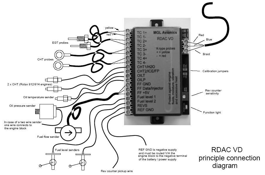
5 tweezers. After a short while you will see the ambient temperature reading increase and after a while it will start at a low temperature, increasing as long as you keep the jumper closed. When the indication is correct (about 2-4 degrees above ambient), remove the jumper. Calibrating the thermocouple amplifier requires an exact 2.49mV DC source with low impedance connected to TC1. Once you have connected this source, verify that you have 2.49mV exactly on the TC1 terminal using an accurate millivolt meter. Now close the TC cal link. After a short while you will see the indicated temperature on TC1 drift towards a temperature reading that is 600 degrees Celcius plus ambient (for example, if your ambient temperature reading on the RDAC is 20 degrees, the reading will be adjusted for 620 degrees). Once the correct target temperature has been reached, you can remove the link. This calibration adjusts TC2 to TC4 as well. Installation of the RDAC VD The RDAC VD must be installed with the following requirements met: a) The RDAC must not be exposed to direct engine vibrations. Never mount the RDAC on the engine itself. Mount the RDAC on on the aircraft's firewall or similar suitable structure. b) The RDAC must be installed so extreme heat from the engine cannot damage it. c) The RDAC must be mounted in a position where it is protected from any engine oils or other engine fluids including water. d) If required the RDAC should be mounted inside a protected enclosure if it is otherwise not possible to protect it from environmental exposure such as rain. e) All wires to the baseboard must be secured such that it is not possible for any wire to be damaged due to chafing or that any wire can loosen itself from its connection terminal. f) If the RDAC is operated in conditions that may lead to corrosion of exposed electrical metal parts, suitable protection is a mandatory requirement. g) The RDAC includes very good protection against voltage transients on the power supply. However, in cases where severe transients containing a large amount of energy are expected, additional, external protection may be required. h) All signal connections that terminate in any of the RDAC terminals must never be allowed to contain dangerous high voltages such as can be created by ignition systems or inductive devices. In particular never route such cables alongside HT ignition leads. RDAC VD principle wiring diagram
6 The following diagram shows a basic connection sample for various sensors. The actual connection of sensors depends on your application and setup in the display unit (instrument). Normally, in cases of multiple EGT/CHT thermocouple sensors, EGT sensors start from TC channel 1 while the CHT channels follow. The starting channel for CHT channels depends on your instruments setup. CHT1/H2O is used for either a NTC type water temperature sender or the CHT probe of a Rotax 912/914 engine. CHT2/ICE/FP is used for a LM335 based ice waring sensor or the second CHT probe of a Rotax 912/914 engine or a fuel pressure sender.
7
8 RDAC EMS unit thermocouple inputs Typical Thermocouple setup, here shown for four EGT probes. Please note that the probes are colour coded. Yellow wires must connect to the + terminals and the red wires must connect to the - terminals. Thermocouple inputs details The RDAC VD EMS provides for up to 4 thermocouple inputs for use with EGT and CHT probes. Both K as well as J type probes can be used. K types are used for EGT probes while most CHT probes are also K types. Some makes of CHT probes are J type. Probe types are selected in the sender setup menu of your instrument. Important: Incorrect selection will lead to incorrect temperature display. The RDAC VD EMS will accept both grounded and isolated thermocouple probes. Your only consideration in case of the more common grounded configurations is that you need to ensure that the thermocouple mounting position (Exhaust flange, etc) is at the same electrical potential as the negative supply line of the RDAC VD (REF GND). Probe usage depends on your setup and kind of your instrument. Usage of thermocouple inputs with various display units: RDAC VD thermocouple guidelines The thermocouple amplifier is a precision device providing full cold junction compensation and bow voltage correction. In addition the amplifier measures
9 and corrects for its own errors. This results in very accurate measurements providing you install high quality probes. Here are some guidelines: EGT Probes: select probes that are made from 316 stainless steel and that use glass-fiber insulated conductors. Teflon insulated conductors as found in many cheap probes introduce errors as the insulation melts moving the measuring point towards the mounting bolt which transfers a lot of heat to the exhaust material. This results in under reading probes. Stay away from probes that use simple plastic heat shrink sleeving it does not last. Choose probes that use a generous amount of stainless steel spring as strain relief. The Bolt itself should be stainless as well or it will rust very quickly. CHT probes: These are made from washers to fit spark-plug bases. Temperatures are considerably lower so most thermocouple cables will work without problems. The biggest area of concern should be the connection of the thermocouple cable to the washer. This often breaks after the spark plug has been changed a few times. Choose a probe that is suitably reinforced at this point for a long and trouble free life. EGT and CHT probes supplied by MGL Avionics are of highest quality. We recommend that you consider using our probes if at all possible. Warning: Four stroke engines produce much hotter exhaust gases compared to two stroke engines. Do not use EGT probes made from lower grade stainless steel (for example 310), these probes will not withstand the high temperatures and can fail as the metal gets very soft at 800 degrees C. Many four strokes (such as the Rotax 912) will produce exhaust gases of up to 850 degrees C. Important installation note: EGT and CHT probes use wire made from plain Iron and other basic metals. As a result these probes are not able to withstand much flexing of the wires due to engine vibrations. Avoid making nice looking coils or similar constructions that will result in excessive vibration or flexing of the wire. Route the cables from the probe points tightly along suitable engine mounting points eliminating any chance of unnecessary wire flexing during engine operation.
10 Connecting coolant temperature, oil temperature and oil pressure senders. This drawings shows the connection of a coolant temperature probe, a oil temperature probe and a oil pressure sender. Note that all of these probes require a good electrical ground connection to the engine block so they should never be installed using sealant or PTFE sealant tapes. The RDAC VD REF GND connection should also be wired to the engine block. The RDAC VD supports various types of temperature senders and well as oil pressure senders. These are selected in the relevant sender setup menus of your instrument. Please note that the CHT1 and CHT2 terminals are used in case of a Rotax 912 or 914 engine to interface to the two built in CHT senders. These senders are standard VDO oil temperarature senders. Coolant and oil temperature senders are mostly NTC resistors. These are resistors that vary their resistance with temperature. These senders come in a wide variety so ensure that the sender you are using is compatible with the instrument and that you have selected the correct probe type in the relevant setup menu.
11 RDAC Fuel flow sender installation Note: Direction of fuel flow Indicated by arrow on sender RED wire Fuel Flow Sender Supply BLUE wire Fuel Flow Sender signal Braid Fuel Flow Sender Ground Braid BLUE RED Warning: Incorrect wiring can damage both the RDAC unit as well as the flow sender. The optional Fuel Flow Sender is highly recommended for use with Stratomaster instruments. It provides instantaneous readouts of hourly fuel usage, and both time and distance estimates on remaining fuel in flight. You can also verify the performance of your fuel pump during the pre-takeoff engine run up a very valuable check! Further, it is possible to set up the instruments to calculate Fuel remaining by subtracting fuel used from a value entered when you filled your tank(s). In this case you may omit the installation of the optional fuel level sender. Please note that the installation of the Fuel Flow sender should be done in such a fashion that dirt or debris from the fuel tank cannot lodge inside the flow sender. These will not block you fuel flow but may lead to the impeller inside the sender jamming. It is usually sufficient to mount the Flow sender AFTER the fuel filter but before the fuel pump. It is a good idea to provide a small reservoir such as a primer bulb between the flow sender and the fuel pump.
12 Primer bulb or small reservoir Fuel filter Fuel Tank Fuel flow sender Fuel pump As indicated in the recommended fuel flow sender installation drawing, it can be of advantage to install the flow sender in such a fashion that the inlet points slightly down and the outlet points slightly up. This prevents vapor from forming a bubble inside the flow sender. We strongly recommend to mount the flow sender in such a fashion that the impreller rests on only one bearing. This is achieved if you mount the sender such that the surface with the arrow faces upwards. Mounting the sender like this results in the best performance at low flow rates as only very little friction is present. The flow sender is delivered with a small jet that can be installed in the flow sender inlet. Installation of this jet is recommended for engines with fuel flow rates lower than about 30 liters per hour. This would apply to most small two and four stroke engines. Stratomaster instruments are shipped with the Fuel sender calibration set for the jet installed. In a good installation you can expect about +/- 3% maximum flow reading error with this factor. You can calibrate the flow sender yourself to a higher degree of accuracy if you so desire. Recommended procedure to calibrate the fuel flow sender: Note: You must disable the Fuel Level sender if you have one installed first. Fill your tank exactly to a known level (for example 50 liters). Set your fuel level to 50 liters using the Main Menu. If required you may have to disable the fuel level sender first using the Mode Menu. Fly your aircraft for a period that you know will use approximately 20 liters of fuel. The exact fuel burn is not important, just burn about 20 liters of your fuel. At the end of your flight the instrument should give you a reading of how much fuel you have left the reading should be about 30 liters left. Now place your aircraft in exactly the same position that you used when you first filled the tank and refill the tank to 50 liters using a measuring jug. You should find that you need 20 liters of fuel to refill to 50 liters. If you find that the instrument under or over reads the fuel used, you should perform a simple adjustment of the Fuel Flow sender calibration factor. This is outlined in the Owners Manual.
13 Example: Actual fuel used: 21.5 liters, Stratomaster fuel burn calculated 29.7 liters left in tank. This means the Stratomaster measured = 20.3 liters. We are under reading by 1.2 liters. Default calibration factor in Fuel Flow setup (Basic device setup menu) = Let the corrected calibration factor be X. X = (21.5 * 7000) / 20.3 X = The closest setting you can enter as factor is Enter it into the unit and you are done! Repeat the above procedure to verify that your flow sender is now reading correctly. Please note: Before you calibrate the flow sender ensure there are no problems with your installation. We find the senders are very accurate if everything is installed and working properly. If your fuel burn indication is out by a large amount you have a problem that you should not attempt to fix by fiddling with the calibration factor! Please ensure that no fuel vapor can be trapped inside the sender housing in the form of bubbles. Due to the low fuel flow rates the bubbles will prevent the tiny impeller from turning freely, You can verify the turning of the impeller. You should notice three dark spots that are just visible in the inside of the fuel flow sender. These are small magnets that are attached to the impeller. With fuel flowing you should see the magnets turning. The best defense against vapor bubbles is to install the flow sender in such a way that the bubbles can escape. The easiest way is to point the outlet slightly upwards and the inlet (with the jet) slightly downwards. Another possible problem is the fuel sender jet. When you install it, do not damage it. Use a drill bit of suitable diameter to push the jet all the way the opening of the jet must be just in front of the impeller. YOU NEED TO APPLY SOME FORCE TO INSERT THE JET ALL THE WAY. THE JET MUST BE LOCATED RIGHT IN FRONT OF THE IMPELLOR. YOU CANNOT PUSH THE JET TOO FAR.
14 (Fuel flow sender continued from previous page) Using other Flow Senders It is quite possible to use Flow Senders other than the Stratomaster device. In this case ensure that the Sender outputs a 5V TTL square wave or a similar signal. The Stratomaster interface electronics will adapt to a variety of different voltages and pulse shapes as it contains a schmidt-trigger input stage. The calibration factor can be entered in a wide range making the unit particulary suited to other Flow senders. The supply output terminal for the Sender provides a positive, regulated 5 volt output. This may be used to power the Flow Sender provided the Sender will not draw more than 40 ma of current. Should your sender require a higher voltage or more current, then you must supply the sender from a different power source. Exceeding the rating on the Stratomaster Flow sender supply terminal can affect the operation on the unit negatively or even damage it. Recommended Calibration Factors for the MGL Avionics dual range flow sender: With jet installed = Recommended with flow rates below 30 liters/hour maximum. Without jet installed = Recommended with flow rates above 30 liters/hour. Please refer to the leaflet included with the Flow Sender for information on pressure drop vs. flow rate, wetted materials etc. It is your responsibility to ensure that the flow sender used is compatible with the fuels you intend using. We have found the MGL Avionics sender to be very compatible with automotive fuels used in South Africa, many of which contain methanol. 100LL AVGAS also appears not to harm the sender in any way. We have exposed a sender continuously to our automotive fuels for a duration of two years without any noticeable ill effect on the sender. However, despite this MGL Avionics or its appointed agents cannot assume responsibility for any incident or damage, even loss of life by whatsoever cause connected with the fuel flow sender or the Stratomaster Flight Instrument. Usage of this or other senders is your own sole responsibility. If you do not agree with the above statement you must not use the fuel flow sender. Note to Pilots: (Even though this is the installation manual) You must always have a visual indication of the fuel level available, either by means of a sight glass, direct tank observation or a known, reliable secondary fuel level gauge. Fuel level indication by means of calculated fuel burn is subject to errors both by entering incorrect starting fuel levels as well as
15 mechanical problems causing the flow sender impeller to turn too slowly, resulting in under reading fuel burn and thus over reading remaining fuel. As pilot in command of an aircraft it is your responsibility to ensure that you have sufficient fuel to reach your intended destination. Always ensure that you have a generous amount of reserve fuel and never use your reserve fuel except in an emergency if it is unavoidable.
16 RDAC Fuel injection system monitoring +12V rail Fuel Injector Join here to monitor injector firing times Typical low side fired fuel injection system Should you want to monitor fuel flow directly by means of measuring the fuel injector opening time, the above arrangement can be used. You can use both high or low fired injectors (most systems are low side fired as shown above). After you have connected the system as shown above you can proceed to set up the system. (don t forget that you need a connection from the RDAC ground terminal to the engine block (at the same potential as the battery negative). a) Select high or low side fired injector in the Mode Menu (InjectorH and InjectorL). b) Enable the flow sender in the Mode Menu. c) Select a suitable K-factor in the calibration menu to give you correct rate of flow. A good starting value may be in the range. Increase to lower indicated flow and decrease to have a larger indicated flow. Flow through the injectors may not be 100% linear with switching times due to various effects. However, it is possible to obtain very good performance from this flow monitoring system if you keep the following in mind:
17 Calibrate the K-factor so flow indication is accurate during cruise, the period your engine spends most of its active time at. Ensure that you have a correctly working fuel pressure regulator. The more constant your fuel pressure, the more accurate the flow indication. Never use this or any other flow system as your only fuel level indication. This is not the intended purpose of a flow measuring system and this can be dangerous if for whatever reason incorrect flow is indicated.
18 Connecting fuel level sender(s) Typical float based level sender We recommend VDO senders Connect flange of sender to negative supply (ground). Dotted connection is for fuel level sender two. The Stratomaster RDAC VD EMS permits the connection of one or two standard automotive fuel level senders. These senders can be obtained at automotive spares outlets at reasonable cost. When you choose a float level sender, ensure that you select a model that is sturdy and promises reliable and long lifetime. In particular, select a model that does not have any metal parts that can rust. The RDAC VD EMS can interface to a large variety of these fuel level senders. It does not matter if the sender resistance increases or decreases with the fuel level as long as it changes. The calibration procedure outlined Set fuel tank in the owners manual describes in great detail the procedure to follow. In essence, the calibration procedure will measure the resistance of the fuel level sender at various fuel levels and then work out the readings in between those known settings. Typical fuel level senders that can be used with the RDAC VD EMS have resistance ranges in the region of 100 ohms to 500 ohms.
19 You can connect capacitive senders as well. These generally come in two types: The first emulates a normal resistive probe and is simple to connect and use as a result. The second type has a voltage level output. These can be used if the voltage can be set to a range of about 0-2.5V. Higher voltage levels will result in the instrument assuming a problem. The RDAC VD supports one or two fuel tank level senders. You need to enable these in the relevant setup menu of your instrument (usualy the mode setup menu). Safety Hazard! Please read this: Be careful when installing fuel level senders into fuel tanks. Ensure that the fuel tank is completely empty when you proceed with the installation. Ensure that the fuel tank is well ventilated and does not contain any fuel vapors these are highly explosive when mixed with air. Ensure that at all times the ground connection (the connection of the fuel level sender mounting flange) is securely connected to the aircraft frame (in case of a metal frame) and to the negative terminal of the battery. In addition the negative terminal of the battery must at all times be connected to the Supply ground terminal of the RDAC VD EMS. Please note this wiring is critical and must never break in flight. It would be possible to create electrical sparks in the fuel tank if your wiring is faulty or incorrect. The consequences of this can be imagined. This has nothing to do with the RDAC EMS itself but is a general hazard for any automotive fuel level sender installation. If you have no experience with electrical wiring, PLEASE delegate the task to a qualified automobile electrician or electronics technician. If you need to remove the RDAC VD EMS, please first disconnect and secure the fuel level sender wire before disconnecting anything else.
20 Connecting the rev counter if used on other magneto systems such as found on Jabiru and similar engines. REV counter wire from ignition system After you have connected the rev counter terminal to the signal source you need to set the number of pulses per 10 revolutions in the Calibration Menu. The calibration itself depends on your engine type and what kind of signal you are using. Typical sources are: Magneto coils (suitable signal at the kill switch). Primary (low voltage) side of ignition coil, at contact breaker or electronic ignition module. RPM counter output of electronic ignition systems (for example Bosh Motronic). RPM pickup devices such as hall-effect sensors on flywheels etc. Typical calibration settings are 10 or 20 for most engines. Other pulse counts per 10 revolutions are also possible for some engines. Please note: On some of the Stratomaster instruments pulse counts are entered as pulses per ten revolutions, on others it is pulses per single revolution with a decimal point (i.e. 1.0). The rev counter input on the RDAC can be used with signals from about 5Vpp to as much as 100Vpp. A noise filter is included that results in the input ignoring any noise signals as long as this is below the detection threshold of about 2.5Vpp. The input impedance of the rev counter input is approximately

21 10Kohm. You can use series resistors as well as load resistors for applications that have unusual signals. Adjusting rev counter sensitivity The rev counter has a sensitivity adjustment trimmer as shown in the picture below. Adjust this trimmer using a small screwdriver such that you get stable RPM readings over the entire rev band of your engine. If your sensitivity is too high, you may get unstable RPM readings (usually at higher RPM as electrical noise in the ignition system increases). If the sensitivity is too low the RPM reading may remain at zero.
22 Rev counter pickup for Stratomaster instruments fitted to automotive engines Conventional contact breaker ingnition system Use the tacho line if your system has such a signal. Connect rev counter input on RDAC or instrument to this line. Ensure you have a connection from RDAC ground or instrument ground to engine block. Electronic ignition system with conventional ignition coil Connect rev counter input on RDAC or instrument to this line. Ensure you have a connection from RDAC ground or instrument ground to engine block.

23 Connecting the rev counter on a two stroke Rotax Typical connection in case of a Rotax two stroke engine with Ducati dual ignition. Grey wire from Rotax DCDI ignition system Engine with generator such as Rotax 503, Rotax 582 etc Most instruments assume as a default that you will be connecting a Rotax with DCDI ignition system. Such a system produces 6 pulses for every revolution of the engine. Other engines can be used but you must adjust the rev counter calibration setting accordingly (Device basic setup menu). The value entered is for 10 revs. On some instruments a decimal point is shown in the setup for the rev counter calibration. If you have one of these, enter the number as pulses per revolution. For example, for the Rotax 503 or Rotax 582 you would enter 6.0. Rotax 503,582,618 DCDI - value 60 (6.0). Rotax 912,914 value 10 (1.0). The rev counter input can be connected to a variety of different sources such as the low voltage side of a ignition coil (at the points contact breaker) or to rev counter outputs of fuel injection computers. Note: Some Rotax engines may require that a 220 ohm ballast resistor is fitted between the rev counter input and the REF GND terminal. This resistor should be fitted if you cannot obtain stable RPM throughout the range regardless of any setting of the rev counter sensitivity adjustment.
, two EGT probes should be connected, one for each exhaust stack. You can connect four EGT probes if you like.")
24 Connecting a Rotax 912 The Rotax 912/914 contains two built in NTC type CHT temperature senders. In addition oil temperature and oil pressure sender is provided as standard. Due to the fact that the 912 has two carburetors (one for each side of the engine), two EGT probes should be connected, one for each exhaust stack. You can connect four EGT probes if you like. You would use TC1 and 3 as one pair and TC2 and 4 as the other pair. Each pair monitors one side of the engine. CHT1 and CHT2 connect to the standard CHT senders, again one for each side. Connect oil pressure and oil temperature and you are done.
25 In the Stratomaster Ultra and similar instruments, use Engine quick select to choose the 912 setup and then use Engine detail setup to change any settings to your liking. Connect the Rev counter wires (blue/yellow and white/yellow) as follows: One of the two wires needs to be connected to ground (engine block), the other to the REV counter input. Do not forget to set the rev counter setup in the Basic setup menu or Calibration Menu (depending on instrument type). Select a value of 1.0 as the engine generates one pulse for every revolution. Please note: Most of the senders are grounded configurations This means they connect electrically to the engine block. It is vital for good and stable readings that you connect the Ground terminal of the RDAC to the engine block using a short, good quality electrical connection. Never use sealant or PTFE tape on the threads of the senders. This may electically isolate the senders which will result in incorrect indications. The threads on these senders are expanding threads which are designed to create a tight metal to metal seal.

26 Connecting a Rotax 503 or 582 This diagram shows EGT, CHT and water temperature sender locations and wiring based on a Rotax 582. This is a water cooled engine so CHT senders should be viewed as optional. For a Rotax 503 or similar aircooled installation, proceed similar but omit the water temperature sender and wiring. Please note that the ground connection (black wire) from the RDAC must be connected to the engine block as shown. Select a suitable point on your engine block for this connection. The engine block itself needs to be connected to the negative supply, in all cases this should be a direct connection to your batteries minus terminal. This should be a thick copper cable with a very low resistance and it needs to be as short as possible. This requirement is even more severe if you are using electric start as the very considerable currents required by the starter motor will be using this connection.

27 Connecting a Bendix magneto as RPM source The above drawing shows the connection required if you would like to connect a magneto as RPM source. Shown is a typical Bendix magneto as used on Lycoming and other aircraft engines. You should find a wire connected to a terminal on the magneto that originates from your magento kill switch (or starter switch). The terminal is often refered to as a P-terminal. Connect a wire as shown and connect this to the Rec counter input of the RDAC. We strongly recommend that a resistor is inserted into your wire as shown. A good value would be ohms (10K). A normal 1/4 W resistor is just fine. The above circuit can also be used on other magneto systems such as found on Jabiru and similar engines.
RDAC X. Technical installation document
 RDAC X Technical installation document Models: A 4TC channels B 12TC channels C 4TC channels plus Manifold pressure sender D 12TC channels plus Manifold pressure sender RDAC X general The RDAC X consists
RDAC X. Technical installation document
 RDAC X Technical installation document Models: A 4TC channels B 12TC channels C 4TC channels plus Manifold pressure sender D 12TC channels plus Manifold pressure sender RDAC X general The RDAC X consists
RDAC XF RDAC XF and RDAC XF MAP
 RDAC XF RDAC XF and RDAC XF MAP RDAC XF MAP version has a map sensor fitted. Input Connections TC 1 to 12 Inputs for use with thermocouple temperature probes. Typcally used for EGT probes (K-types) and
The E-3 can measure up to 4 EGT/CHT channels, a RPM input, a universal temperature sender input and a universal pressure sender input.
 E-3 Universal engine monitor Operating Manual English 1.01 Introduction The E-3 universal engine monitor combines in one compact 2.25 format instrument all that is needed to monitor the majority of smaller
Installation guide for the Stratomaster Flight digital aircraft instrument Page 1
 Installation guide for the Stratomaster Flight digital aircraft instrument Page 1 Before you commence any attempt at installing this instrument it is your duty to familiarize yourself with the relevant
E-1. Introduction. 1 Features. Universal engine monitor. Operating Manual English 1.00
 E-1 Universal engine monitor Operating Manual English 1.00 Introduction The E-1 universal engine monitor combines in one compact 3.125 format instrument all that is needed to monitor the majority of smaller
Stratomaster Maxi Single
 Stratomaster Maxi Single RV-3 Universal Engine RPM and Rotor RPM display The RV-3 unit is a 3.5 instrument providing a universal rev counter that can be adapted to a variety of roles. Typical uses are
FUEL FLOW SENSOR INSTALLATION GUIDE
 Table of content FUEL FLOW SENSOR INSTALLATION GUIDE Revision 1 1 Features... 1 2 Installation... 2 2.1 Overview... 2 2.2 Fuel compatibility... 2 2.3 Ranging jet... 3 2.4 Flow direction... 4 2.5 Location...
All information is displayed in an easy to read format on a high resolution wide viewing angle cd/m2 sunlight readable color display.
 Vega EMS-1 Universal Engine Monitoring System Operating Manual English 1.01 Introduction The Vega EMS-1 is a 2 1/4 (57mm) universal engine monitor color display instrument. The EMS-1 contains all the necessary
FF-1. Introduction. 1 Features. Fuel management computer for single or dual fuel tanks. Operating Manual English 1.04
 FF-1 Fuel management computer for single or dual fuel tanks Operating Manual English 1.04 Introduction The FF-1 fuel management computer is a 2.25 instrument intended for efficient monitoring of fuel related
Stratomaster Smart Single
 Stratomaster Smart Single Universal Engine RPM and Rotor RPM display The unit is a 2.25 instrument providing a universal rev that can be adapted to a variety of roles. Typical uses are engine RPM displays
MGL Avionics EFIS G2 and iefis
 MGL Avionics EFIS G2 and iefis Guide to using the MGL RDAC CAN interface with the LAD AERO Injection Kit on ROTAX 912-912S General... 3 Data connections... 3 LAD AERO ROTAX 912 engine data from ECU...
Stratomaster Maxi Single
 Stratomaster Maxi Single TP-2 Combined Oil or fuel pressure gauge Oil or Coolant temperature gauge The TP-2 Temperature/Pressure gauge is a 3.5 instrument intended for display of either the following selections:
Temperatures can be displayed in degrees Celsius or degrees Fahrenheit from -100ºC to 1200ºC (-148ºF to 2192ºF).
.") Velocity TC-3 One to Twelve channel thermocouple (EGT/CHT) indicator Operating Manual English 1.02 Introduction The TC-3 thermocouple display unit is a 12 channel 3 1/8 instrument that contains all the
Velocity TC-3 One to Twelve channel thermocouple (EGT/CHT) indicator Operating Manual English 1.02 Introduction The TC-3 thermocouple display unit is a 12 channel 3 1/8 instrument that contains all the
ENGINE MONITORING SYSTEM OPERATOR'S MANUAL. Release: M. MGL Avionics. P O Box 286 Sundowner 2161 South Africa
 Table of Contents ENGINE MONITORING SYSTEM OPERATOR'S MANUAL Release: 020826M MGL Avionics P O Box 286 Sundowner 2161 South Africa Email: rainier@iafrica.com Web: http://users.iafrica.com/r/ra/rainier/strato.htm
RV-3. Introduction. 1 Features. Universal engine RPM and rotor RPM indicator. Operating Manual English 1.00
 RV-3 Universal engine RPM and rotor RPM indicator Operating Manual English 1.00 Introduction The RV-3 universal engine RPM and rotor RPM unit is a 3 1/8 instrument providing a universal RPM counter that
RDAC XG Engine monitoring module for MGL Avionics CAN bus compatible EFIS systems.
 RDAC XG Engine monitoring module for MGL Avionics CAN bus compatible EFIS systems. This Engine monitor is fully compatible with the larger RDAC XF device. Compared to the RDAC XF the following inputs are
Lycoming Engine Sender Installation Guide
 3401 Airport Drive Ste E, Torrance, CA 90505. Tel: 1-877-8FLYING Fax: 1-310-534-2282 e-mail: sales@mglavionics.com Web: www.mglavionics.com MGL Avionics EFIS Lycoming Engine Sender Installation Guide This
The TC-4 is a 2 1/4 sunlight readable 4 channel thermocouple color display instrument.
 Vega TC-4 One to four channel thermocouple (EGT/CHT) indicator Operating Manual English 1.00 Introduction The TC-4 is a 2 1/4 sunlight readable 4 channel thermocouple color display instrument. The instrument
Blaze TC-6. Introduction. 1 Features. Twelve channel thermocouple (EGT/CHT) indicator. Operating Manual English 1.00
 indicator. Operating Manual English 1.00") Blaze TC-6 Twelve channel thermocouple (EGT/CHT) indicator Operating Manual English 1.00 Introduction The TC-6 is a 3 1/8 sunlight readable 12 channel thermocouple color display instrument that contains
Blaze TC-6 Twelve channel thermocouple (EGT/CHT) indicator Operating Manual English 1.00 Introduction The TC-6 is a 3 1/8 sunlight readable 12 channel thermocouple color display instrument that contains
MAP-1. Introduction. 1 Features. Manifold Pressure and RPM Indicator. Operating Manual English 1.03
 MAP-1 Manifold Pressure and RPM Indicator Operating Manual English 1.03 Introduction The MAP-1 is a 2 1/4 instrument which can measure pressures in the range of 0.25 bars (3.6 PSI) to 2.5 bars (36.2 PSI)
EMS-2. Introduction. Features. Engine Management System. Operating Manual English 1.07
 EMS-2 Engine Management System Operating Manual English 1.07 Introduction The EMS-2 is a multifunction engine information display and early warning engine monitoring system. It has been specifically designed
EFIE Wideband O2 (Electronic Fuel Injector Enhancer) Installation & Operating Instructions.
 Installation & Operating Instructions.") EFIE Wideband O2 (Electronic Fuel Injector Enhancer) Installation & Operating Instructions. The EFIE is not intended to be a fuel saver by itself. The EFIE is designed to be used in conjunction with fuel
EFIE Wideband O2 (Electronic Fuel Injector Enhancer) Installation & Operating Instructions. The EFIE is not intended to be a fuel saver by itself. The EFIE is designed to be used in conjunction with fuel
Switch select of sender types:
 Full sweep minor gauges wiring: B -------------------------------------------------- battery or +12V input. L -------------------------------------------------- LED illumination, for back lighting, dimmable.
Tecomotive - tinycwa User Manual
 Tecomotive - tinycwa User Manual Overview Contents - tinycwa controller - Fuse holder - Fuses (15A/30A) - Connector 8 pin (controller) - Connector 4 pin (water pump) - Connector 2 pin (temperature sensor)
FF-3. Introduction. Fuel management computer for single or dual fuel tanks. Operating Manual English 1.02
 FF-3 Fuel management computer for single or dual fuel tanks Operating Manual English 1.02 Introduction The FF-3 fuel management computer is a 3 1/8 instrument intended for efficient monitoring of fuel
EGT Plus Instructions
 Computech Systems, Inc. 29962 Killpeck Creek Ct. Charlotte Hall, MD 20622 301-884-5712 EGT Plus Instructions The Computech Systems EGT Plus is designed to monitor not only exhaust gas, liquid, tire and
INSTALLATION GUIDE Multi-Gauge Set with sending units Part Number: M 9999
 Made in America Lifetime Guarantee Thank you for purchasing this instrument set from Intellitronix. We value our customers! INSTALLATION GUIDE Multi-Gauge Set with sending units Part Number: M 9999 * Always
SP5 INSTALLATION AND SETUP MANUAL
 SP5 INSTALLATION AND SETUP MANUAL 1 Installation 1.1 Introduction The SP5 System consists of a Data Acquisition unit (DAQ) with two complete Roller control channels, each Roller Control Channel consists
Stratomaster Ultra for Rotorcraft
 Stratomaster Ultra for Rotorcraft Model RL with RDAC V EMS Owner's Manual & Installation guide MGL Avionics Physical: 5 Fuchsia Street, Heldervue, Somerset West Postal: Postnet Suite 325, Private Bag X15,
MGL Avionics AvioGuard. Fault protected, wide input range, isolated, DC to DC converter for avionics applications
 MGL Avionics AvioGuard Fault protected, wide input range, isolated, DC to DC converter for avionics applications General The MGL Avionics AvioGuard is a fault protected DC to DC converter. It is able to
Stratomaster Smart Single
 Stratomaster Smart Single GF-1 Tilt compensated dual range aviation G force meter The GF-1 is a 2.25 instrument that displays the acceleration forces acing on the aircraft. Able to measure out of vertical
Throttle Cable Pull - Patent Pending By: NetGain Controls, Inc.
 Throttle Cable Pull - Patent Pending By: NetGain Controls, Inc. Powering the future! Installation Guide 2011 All Rights Reserved NetGain Controls, Inc. 1 of 8 Introduction Thank you for purchasing a NetGain
R & D SPECIALTIES ROTROL I USER'S MANUAL
 R & D SPECIALTIES ROTROL I USER'S MANUAL TABLE OF CONTENTS INTRODUCTION...2 SPECIFICATIONS...2 CONTROLS AND INDICATORS...3 TIME DELAYS...4 INSTALLATION...5 SYSTEM OPERATION...9 TROUBLESHOOTING...13 OPTIONAL
EV Display User Guide
 EV Display User Guide CleanPowerAuto LLC Brief Description: EV Display is designed to track battery state of charge and other related data in battery powered Electric Vehicle. EV Display is primarily designed
Ch 4 Motor Control Devices
 Ch 4 Motor Control Devices Part 1 Manually Operated Switches 1. List three examples of primary motor control devices. (P 66) Answer: Motor contactor, starter, and controller or anything that control the
Marine Exhaust Temperature Alarm. COMPONENTS
 Marine Exhaust Temperature Alarm. Model: SM0012 INTRODUCTION COMPONENTS Marine water cooled exhaust systems are designed to withstand temperatures of up to about 120 C. However the exhaust gases from the
User s Manual. Automatic Switch-Mode Battery Charger
 User s Manual Automatic Switch-Mode Battery Charger IMPORTANT Read, understand, and follow these safety rules and operating instructions before using this battery charger. Only authorized and trained service
USER'S MANUAL FOR THE ENGINE INFORMATION SYSTEM
 USER'S MANUAL FOR THE ENGINE INFORMATION SYSTEM Grand Rapids Technologies Incorporated 889 76th St SW #2 Byron Center, MI 49315 (616) 583-8000 Fax (616) 583-8001 1 1. USING THIS MANUAL... 5 2. USING THE
Tecomotive - tinycwa - User Manual Intercooler Version
 Tecomotive - tinycwa - User Manual Intercooler Version Operation Overview When activated the controller is measuring the coolant temperature and the rate of increase with the connected temperature sensor.
User Manual. T6 Tachometer. Online: Telephone: P.O. Box St. Petersburg, Florida 33736
 User Manual T6 Tachometer Online: www.phareselectronics.com Telephone: 727-623-0894 P.O. Box 67251 St. Petersburg, Florida 33736 Table of Contents Overview... 1 Description... 1 Wiring... 1 T6 Tachometer
LAMBDA 2 USER MANUAL VPV-Motorracing Electronics
 LAMBDA 2 USER MANUAL 2012 VPV-Motorracing Electronics TABLE OF CONTENTS TABLE OF CONTENTS...2 1 TECHNICAL DETAILS...3 1.1 General...3 1.2 Technical specification...4 2 ASSEMBLY...4 2.1 Sensor assembly...4
with lcd display 12-42v
 instructions for: AUTO PROBE with lcd display 12-42v MODEL No: PP7 Thank you for purchasing a Sealey product. Manufactured to a high standard this product will, if used according to these instructions
Model 2500 Horsepower Computer System User Manual
 Model 2500 Horsepower Computer System User Manual Manufacturered by: Ries Labs, Inc. 2275 Raven Road Farina, IL 62838 Phone: (618) 238-1400 email: admin@rieslabs.com Table of Contents Description ----------------------------------------------------------------
JEEVES. JEEVES Installation Manual. Installation Manual The Easiest Do-It-Yourself Dumbwaiter on the Market
 1 888-323-8755 www.nwlifts.com JEEVES Installation Manual The Easiest Do-It-Yourself Dumbwaiter on the Market This manual will cover the installation procedure step-by-step. The installation of this dumbwaiter
INSTALLATION GUIDE Six Gauge Universal Digital Dash Panel Part Number: DP10002
 Made in America Lifetime Guarantee Thank you for purchasing this digital dash panel from Intellitronix. We value our customers! INSTALLATION GUIDE Six Gauge Universal Digital Dash Panel Part Number: DP10002
Mustang. Installation Manual
 1967-1968 Mustang Installation Manual I Table of Contents TABLE OF CONTENTS... II WELCOME TO THE TEAM OF CLASSIC INSTRUMENTS!... III REMOVE ORIGINAL INSTRUMENT PANEL... 1 DETERMINE SPEEDOMETER SIGNAL...
Installation Instructions
 Quick-Mount Visual Instructions for Quick-Mount Visual Instructions 1. Rotate the damper to its failsafe position. If the shaft rotates counterclockwise, mount the CCW side of the actuator out. If it rotates
SOLAR LIGHTING CONTROLLER SUNLIGHT MODELS INCLUDED IN THIS MANUAL SL-10 SL-10-24V SL-20 SL-20-24V
 SOLAR LIGHTING CONTROLLER OPERATOR S MANUAL SUNLIGHT MODELS INCLUDED IN THIS MANUAL SL-10 SL-10-24V SL-20 SL-20-24V 10A / 12V 10A / 24V 20A / 12V 20A / 24V 1098 Washington Crossing Road Washington Crossing,
Only use if safe to do so and at your own risk.
 This product may not be suitable or safe for road usage. The owner accepts ALL responsibility for its use and installation. The product must not be used if malfunction occurs, a suspected malfunction occurs
Internal Combustion Engines
 Internal Combustion Engines The internal combustion engine is an engine in which the burning of a fuel occurs in a confined space called a combustion chamber. This exothermic reaction of a fuel with an
EVAP system, servicing
 Page 1 of 65 20-130 EVAP system, servicing EVAP system components 1 - Cap nut 10 Nm 2 - Cover 3 - Stud For EVAP canister 15 Nm 4 - Sealing piece 5 - Bleed line To EVAP canister purge regulator valve -
Commander IS0128 ISO128E ECR# /04. Tachometer/ Engine Hourmeter
 Commander Tachometer/ Engine Hourmeter Analog Tachometer Digitally displays Hours Engine Has Been Run Fuel Level Other Features if Available: Fuel anagement Fuel Flow in GPH or LPH Total or Trip Fuel Used
SP4 DOCUMENTATION. 1. SP4 Reference manual SP4 console.
 SP4 DOCUMENTATION 1. SP4 Reference manual.... 1 1.1. SP4 console... 1 1.2 Configuration... 3 1.3 SP4 I/O module.... 6 2. Dynamometer Installation... 7 2.1. Installation parts.... 8 2.2. Connectors and
2-PHASE STEPPING MOTOR DRIVER FE Z5 DISPENSE
 2-PHASE STEPPING MOTOR DRIVER FE Z5 DISPENSE For Diaphragm Dosing Pumps FEM 1.02_.55 / FEM 1.09_.55 Controller board package, without pump: ID 160536 Operating and Installation Manual It is important to
Installation and Maintenance Instructions. World Leader in Modular Torque Limiters. PTM-4 Load Monitor
 World Leader in Modular Torque Limiters Installation and Maintenance Instructions PTM-4 Load Monitor 1304 Twin Oaks Street Wichita Falls, Texas 76302 (940) 723-7800 Fax: (940) 723-7888 E-mail: sales@brunelcorp.com
Harris IRT Enterprises Digital Resistance Tester Model XP
 Harris IRT Enterprises Digital Resistance Tester Model 5012-06XP Specifications & Dimensions 2 Theory of Operation 3 Operator Controls & Connectors 4 Test Connections 5 Calibration Procedure 6-7 Options
Error codes Diagnostic plug Read-out Reset Signal Error codes
 Error codes Diagnostic plug Diagnostic plug: 1 = Datalink LED tester (FEN) 3 = activation error codes (TEN) 4 = positive battery terminal (+B) 5 = ground Read-out -Connect LED tester to positive battery
MODEL No s: PP3, PP3K
 instructions for: Power PROBE 3 12-24v MODEL No s: PP3, PP3K Thank you for purchasing a Sealey product. Manufactured to a high standard this product will, if used according to these instructions and properly
In addition, the FF-4 can use the actual ground speed from a RS232 NMEA enabled GPS receiver to determine fuel range.
 Vega FF-4 Fuel Computer Operating Manual English 1.00 Introduction The FF-4 is a 2 1/4 sunlight readable color display instrument intended for efficient monitoring of fuel related information for single
MASTERsine Inverter PXA Series Installation Guide
 Backup Power System Expert TM MASTERsine Inverter PXA Series Installation Guide Important Safety Instructions IMPORTANT: Read and save this Installation Guide for future reference. This chapter contains
EFMS100 USER MANUAL Revision 1.1
 Table of content EFMS100 USER MANUAL Revision 1.1 1 Key specifications and benefits... 1 2 Detailed specifications... 3 2.1 Engine tachometer... 3 2.2 Engine hour meter... 3 2.3 Thermometers... 3 2.4 Battery
Classic Instruments. Installation Manual
 Classic Instruments Installation Manual TABLE OF CONTENTS Welcome from the Team at Classic Instruments! 3 Mounting Gauges 4 4 Speedometer Wiring 5 4 Speedometer Wiring Diagram 5 16 Pulse Signal Generator
CONTROL BOX. Wiring the control box into the vehicle. +12V
 CONTROL BOX Once the display panel is in place, mount the control box within the connecting cable's distance (approximately 3 feet) and secure to the underside of the dashboard. This case does not have
LS0512 Solar Charge Controller
 LandStar LS0512 Solar Charge Controller Nominal system voltage Maximum PV input voltage Nominal charge / discharge current 12VDC 35V 5A Contents 1 Important Safety Information... 1 2 General Information...
The function of this Dynamic Active Probe has divided into three preferences on the screen main Menus:
 1.0 Introduction: This probe is designed to provide an additional help to automotive technicians in trouble shooting of electrical circuits problems in the car. Apart from using the normal multi tester,
Operating and Installation Instructions
 Model Number 40401-c (-sp) Electronic Fuel Pump Operating and Installation Instructions This Product is Patent Pending. Application available upon request CAUTION! This product is to be installed only
TTT802 Gearshift Controller, Part # R1N-S (Standard), -P (Paddleshift)
, -P (Paddleshift)") First, Sign and Date Bln 2009-03-9 Updated, Sign and Date Bln 200-04-29 (0) User Manual TTT802 Gearshift Controller Firmware for R--N-2- TTT802 Gearshift Controller, Part # 2-620-9-RN-S (Standard), -P
First, Sign and Date Bln 2009-03-9 Updated, Sign and Date Bln 200-04-29 (0) User Manual TTT802 Gearshift Controller Firmware for R--N-2- TTT802 Gearshift Controller, Part # 2-620-9-RN-S (Standard), -P
Magnetos (i.e. the Ignition System)
") Magnetos (i.e. the Ignition System) B-17 Technical Session for Flight Engineers 6/10/2017 (with post meeting revisions 6/11/2017) The B-17G (specifically our Texas Raiders, TR) has an electrical system
Magnetos (i.e. the Ignition System) B-17 Technical Session for Flight Engineers 6/10/2017 (with post meeting revisions 6/11/2017) The B-17G (specifically our Texas Raiders, TR) has an electrical system
Classic Instruments Corvette. Installation Manual
 Classic Instruments 1963 1967 Corvette Installation Manual Table of Contents Welcome from the Team at Classic Instruments!... 3 Mounting the Gauges... 4 Gauge Cluster Wiring... 6 Gauge Cluster Wiring Diagram...
Electronics International inc.
 Electronics International inc. MVP-50T Marking and Configuration Requirements Rev B: 6/24/11 Electronics International Inc. will configure the MVP-50T to the range limits, markings and hardware outlined
AFT mid drive kit Trouble shooting guide For 24v to 48V Kelly Controller KBS 48101L-L 100 A peak
 Date: 2016-13-1 AFT mid drive kit trouble shooting guide Rev 1.7 Page 1 of 17 AFT mid drive kit Trouble shooting guide For 24v to 48V Kelly Controller KBS 48101L-L 100 Table of Contents 1. Safety... 2
Part Number DP6003 Chevy Truck Digital Dash YEARS 67-72
 Part Number DP6003 Chevy Truck Digital Dash YEARS 67-72 KIT COMPONENTS: One (1) Digital Circuit Board One (1) Smoked Acrylic See-Through Lens *Peel off protective covering from both sides of lens attached
INDEX Section Page Number Remarks
 INDEX Section Page Number Remarks Synchronous Alternators 2 4 General Fault Finding Capacitors 5 6 Fault Finding & Testing Diodes,Varistors, EMC capacitors & Recifiers 7 10 Fault Finding & Testing Rotors
Motronic September 1998
 The Motronic 1.8 engine management system was introduced with the 1992 Volvo 960. The primary difference between this Motronic system and the previous generation of Volvo LH-Jetronic engine management
Full Sweep Minor Gauge Wiring:
 Full Sweep Minor Gauge Wiring: Notes on Senders: Temp Hi match/vdo 150C: Normally used in Oil temp, 140 280F. Temp Low match/vdo120c: Normally used in water temp, 100 240F. To test the gauges work (oil,
Application Note. Monitoring Bearing Temperature with ProPAC
 Monitoring Bearing Temperature with ProPAC Introduction A mechanical stamping press usually has two or more main bearings for supporting the crankshaft and for allowing smooth and accurate rotation. There
Generator Set Applications FT-10 Network Control Communications Module (CCM-G) Kit
 Kit") Instruction Sheet 10 2004 Generator Set Applications FT-10 Network Control Communications Module (CCM-G) Kit 541 0810 GENERAL INFORMATION This kit contains one Control Communications Module (CCM-G) with
Instruction Sheet 10 2004 Generator Set Applications FT-10 Network Control Communications Module (CCM-G) Kit 541 0810 GENERAL INFORMATION This kit contains one Control Communications Module (CCM-G) with
Series 20 Installation Instructions
 Series 20 Installation Instructions Installation Instructions and field service checklist Read these instructions carefully. Failure to follow them could result in a fire or explosion causing property
Installation Instructions for LED Timing Light
 Daytona Sensors LLC Engine Controls and Instrumentation Systems Installation Instructions for CAUTION: CAREFULLY READ INSTRUCTIONS BEFORE PROCEEDING OVERVIEW The P/N 120001 includes a versatile controller
LTX RF LEVEL SENSOR. Instruction Manual
 LTX RF LEVEL SENSOR Instruction Manual FOR MODELS LTX01, LTX02, LTX05 Intempco Document No: LTX - M01 Rev. 1 Issue Date: April 2005 LTX01 RF LEVEL SENSOR USER MANUAL Software Rev : Rev. Date : June 2004
Classic Instruments Chevelle. Installation Manual
 Classic Instruments 1964 1965 Chevelle Installation Manual Table of Contents Welcome from the Team at Classic Instruments!... 3 Included Mounting Hardware... 4 Mounting Gauges... 5 Wiring Diagram... 6
Sunbeam Alpine Series III, IV, and V Fuel & Temperature Gauges by Michael Hartman and Thomas Hayden Version 1.4 May 9, 2018
 Sunbeam Alpine Series III, IV, and V Fuel & Temperature Gauges by Michael Hartman and Thomas Hayden Version 1.4 May 9, 2018 The Circuit Illustration 1: Temperature & Fuel Gauge Circuits (Series V) Example
Electronic Ballast EVG 2000-T
 Electronic Ballast EVG 2000-T Operating Manual Table of contents 1 Description 1.1 Advantages of this ballast... 3 1.2 Functional principle... 3 1.3 Energization... 4 1.4 Visualization... 5 1.5 Indications
CNV-AT. Introduction. 1 Features. Airtalk serial altitude to parallel Gillham code for mode C transponders. Operating Manual English 1.
 CNV-AT Airtalk serial altitude to parallel Gillham code for mode C transponders Operating Manual English 1.00 Introduction The CNV-AT converter accepts the altitude and local pressure setting information
Classic Instruments Ford F100. Installation Manual
 Classic Instruments 1953 1955 Ford F100 Installation Manual Table of Contents Welcome from the Team at Classic Instruments!... 3 Mount New Gauge Cluster... 4 Instrument Cluster Wiring... 5 Speedometer
MODULE TEST UNIT. Part No: MTU-12 V2.1
 MODULE TEST UNIT Part No: MTU-12 WHITE YEL ORANGE VEHICLE RED 150 Fused + 12 Volt BLACK 150 RED + 12 Volt Out BLACK Out WHITE Pulse ( adjustable by pot) Left High LED will light over 4.5 V Left Low LED
EGT-100 Operations and Installation Manual
 Page 1 of 11 All specification subject to change 2002-2005 EGT-100 Operations and Installation Manual This manual is certified for use with instrument serial number ASL000000 Use of this manual with any
LS0512R Solar Light Controller
 LandStar LS0512R Solar Light Controller Nominal system voltage Maximum PV input voltage Nominal charge / discharge current 12VDC 35V 5A Contents 1 Important Safety Information... 1 2 General Information...
Dealing with customer concerns related to electronic throttle bodies By: Bernie Thompson
 Dealing with customer concerns related to electronic throttle bodies By: Bernie Thompson In order to regulate the power produced from the gasoline internal combustion engine (ICE), a restriction is used
ODYR-25-1 & SLX-25-1 rev. A VACUUM/BOOST PRESSURE, TEMP, and EGT GAUGE
 ODYR-25-1 & SLX-25-1 rev. A VACUUM/BOOST PRESSURE, TEMP, and EGT GAUGE SENSOR CONNECTION: The vac./boost sensor has 1/8 NPT on the end which can be treaded into the intake track, or into a pipe adapter
SBC V In-Car Charger Dual Input (Solar MPPT & DC)
") SBC-5926 12V In-Car Charger Dual Input (Solar MPPT & DC) Operation manual Keep this manual in a safe place for quick reference at all times. This manual contains important safety and operation instructions
SBC-5926 12V In-Car Charger Dual Input (Solar MPPT & DC) Operation manual Keep this manual in a safe place for quick reference at all times. This manual contains important safety and operation instructions
INSTALLATION: HOW IT WORKS: SensiStat Energy Saver Refrigeration Controller. both the holding plate temperature and refrigeration box temperature.
 both the holding plate temperature and refrigeration box temperature. SensiStat Energy Saver Refrigeration Controller HOW IT WORKS:...1 INSTALLATION:...1 OPERATION:...2 CUSTOMIZATION:...4 TROUBLE SHOOTING:...6
Chrysler Electronic Ignition System
 1 of 11 1/6/2010 11:02 PM Chrysler Electronic Ignition System Classic Winnebago's Post by: DaveVA78Chieftain on August 13, 2009, 10:15 PM Components The Chrysler Electronic Ignition System consists of
Instruction of connection and programming of the VECTOR controller
 Instruction of connection and programming of the VECTOR controller 1. Connection of wiring 1.1.VECTOR Connection diagram Fig. 1 VECTOR Diagram of connection to the vehicle wiring. 1.2.Connection of wiring
Universal Wireless Dashboard Y-Dash + Android App Y-Dash GT. User Manual Firmware version 1.6 Software version 2.28 Hardware version 1.
 Universal Wireless Dashboard + Android App GT User Manual Firmware version 1.6 Software version 2.28 Hardware version 1.3 Page 2 is an electronic microprocessor based device that collects analog and digital
Installation Instructions
 Quick-Mount Visual Instructions for Mechanical Installation Quick-Mount Visual Instructions 1. Rotate the damper to its failsafe position. If the shaft rotates counterclockwise, mount the CCW side of the
User Manual. Solar Charge Controller 3KW
 User Manual Solar Charge Controller 3KW 1 CONTENTS 1 ABOUT THIS MANUAL... 3 1.1 Purpose... 3 1.2 Scope... 3 1.3 SAFETY INSTRUCTIONS... 3 2 INTRODUCTION... 4 2.1 Features... 4 2.2 Product Overview... 5
Utilization of Electric Power Laboratory 3 rd Year G2: Testing & Characteristic of MCCB Used in Commercial and Industrial Applications
 G2: Testing & Characteristic of MCCB Used in Commercial and Industrial Applications Contents 1. Laboratory Objective... 4 2. MECHANICAL OPERATION TESTS... 4 2.1 Purpose... 4 2.2 Procedure... 4 2.3 Results...
Installation and Operation Guide. Tundra HD 2500 Power Inverter. for the. Webasto BlueCool Truck System
 Installation and Operation Guide Tundra HD 2500 Power Inverter for the Webasto BlueCool Truck System www.tundrainternational.com www.techwebasto.com BCTSP0063A Table of Contents 1. Introduction 4 1.1 Disclaimer.................................................................................