LAMBDA 2 USER MANUAL VPV-Motorracing Electronics
|
|
|
- Rudolph Potter
- 6 years ago
- Views:
Transcription

1 LAMBDA 2 USER MANUAL 2012 VPV-Motorracing Electronics
2 TABLE OF CONTENTS TABLE OF CONTENTS TECHNICAL DETAILS General Technical specification ASSEMBLY Sensor assembly Display assembly Wire harness assembly Operating voltage and grounding Warning light assembly and electrical connection OPERATION General Warning light adjustment Interpreting the display value WARRANTY...9 2
 with automatic brightness control. Additional adjustable warning light included.")
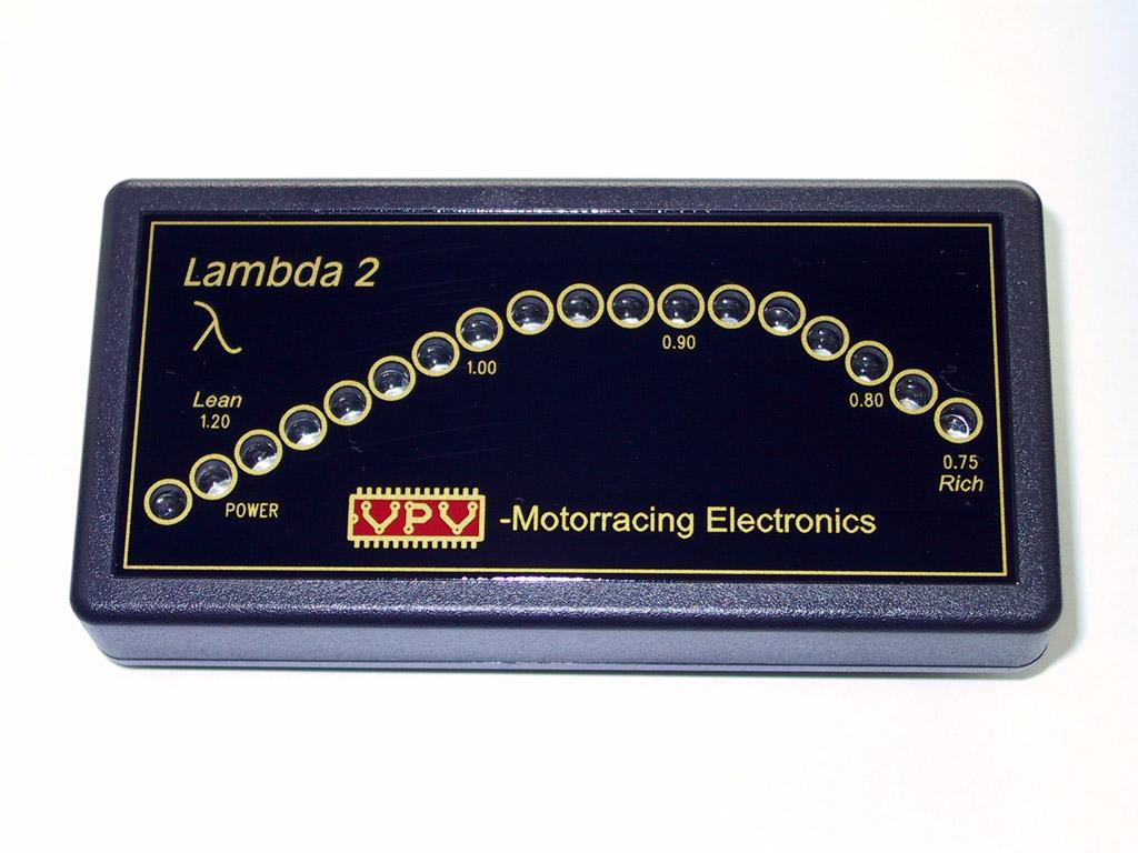
3 1 TECHNICAL DETAILS 1.1 General VPV-Motorracing Electronics LAMBDA 2 is a single channel narrowband air-fuel-ratio gauge with Bosch 4-wire zirconium-type lambda sensor. Display is made using 16 superbright 5mm LEDs (colors red, red-orange, yellow-orange, amber, yellow and green) with automatic brightness control. Additional adjustable warning light included. Contents of the gauge set: -1 pc Display (1) -1 pc Bosch or 733 lambda sensor (2) -1 pc Lambda mounting kit (3), (type may be various) -1 pc Ready-made wire harness (4) -1 pc Warning-LED (5) (available bezel colors: black, silver and gold) -1 pc 2-pole connector body for warning-led (6) -10 pcs Cable tie (7) -1 pc User Manual (not in picture) Picture 1. Contents of the gauge set 3
4 1.2 Technical specification SENSOR: Manufacturer: BOSCH-USA Bosch-type: LSH-25C or similar Part number: or 733 Type: Narrow-band Material: Zirconium Wire count: 4 DISPLAY: Measurement range (lambda-value): Current consumption (display): 200mA max Current consumption (sensor heating): 1-4 A Operating voltage: V DC Overvoltage protection: 24V 600W 10/1000μs Polarity protection: 500V continuous Operational temperature: -40 C-+70 C Material of the enclosure: ABS Material of the front plate: 1mm polycarbonate Dimensions (width x height x depth): 130 x 65 x 25 mm 2 ASSEMBLY 2.1 Sensor assembly Suitable assembly location for the sensor is in the front of exhaust system. Sensor can normally handle C exhaust temperature and assembly should be made this in mind. Lifetime of the sensor is strongly affected by some abnormal situations and these must be taken into account when assembling sensor. - Hot sensor is easily broken if it is exposed to condensing water droplets. Clock 10:00-2:00 is the best assembly location to avoid this. - Antilag systems or any other situation that causes fire in the exhaust system are harmful for the lambda sensors. In these situations it is recommended to assemble sensor further away from engine. Sensor positioning towards the end of the exhaust system can also help to prevent heat shocks to the sensor. - Sensor outer shell and wires should be protected from the flying stones or any other strong mechanical threat. - Sensor wires should be protected from the exhaust temperatures, 200 C max allowed. 4
5 In naturally aspirated engine the optimal sensor position is dependent on the type and dimensions of the exhaust manifold. Natural place for the sensor is the nearest position from the engine where the exhaust gases from all cylinders are thoroughly mixed. This location assures that the measurement value is the mean of the all cylinders. Example: manifold equipped engine; best sensor position is mm from 2-to-1 transition toward the end of the exhaust system. In turbocharged engine the best location of the sensor is after the turbocharger. The exhaust gas pressure affects lambda sensor output voltage so the assembly before turbocharger is not allowed. NOTE! Antilag system may have strong effect on sensor lifetime, please look at the warnings and info earlier in this chapter. When assembling lambda sensors to motorcycles an additional care should be taken into account. Especially on 1-cylinder engine there are a strong exhaust flow pulsations. Strong pulses may cause the air to be sucked inside the exhaust system and this may cause static or pulsating error on measurement. Assembling sensor very near the engine exhaust port can minimize problem. When using lambda sensor together with small diameter exhaust pipe it may cause substantial flow restriction. This can be avoided by assembling sensor with a longer weld bung. This may cause a slightly slower reaction time but it doesn t cause any static error. When assembling sensor the threads of the sensor should be lubricated with suitable high-temperature thread protecting paste. Without this paste the thread may be seized within a very short time. 2.2 Display assembly Natural assembly location for the display is inside the vehicle, normally on the instrument panel. Display is waterproof only on the front side so the assembly to wet location is not recommended. Fixing can be made using the M4 sized screws attached at the backside of the display unit. NOTE! Maximum depth screws can be inserted inside the enclosure is 7mm measured from the outer surface of the display back panel. Fixing can also be made using two-sided adhesive tape. If additional holes are needed for fixing, display should be disassembled before this to avoid any failures to the internal electronics. NOTE! Inside the display there are M4 sized riveted nuts for the fixing screws. If too much force is used for the disassembly of the M4 screws these nuts may become loose. If this happens the usage of the display is not allowed before loose nuts are removed or re-assembled. These loose nuts may cause permanent electrical failures to the display. 5

6 Picture 2. Fixing screws at the rear side of the display 2.3 Wire harness assembly Wire harness route should be chosen to avoid high temperature, sharp edges and strong electrical disturbance. Maximum continuous temperature the cable can withstand is 125 C, wire harness black silicone shield can handle 175 C. Display has good protection against electrical and magnetic fields but it is not recommended to route wire harness near ignition or alternator wires. Strong electrical or magnetic field may cause error to the measurement value. Male-type connectors can be disassembled without special tools to help wire harness routing, guidelines on picture Operating voltage and grounding Display is powered thru two power wires included in the ready-made wire harness: +12V = RED WIRE GROUNDING, -, GND = BLACK WIRE Grounding should be connected to a proper grounding point, alternative on chassis or in the engine. +12V should be connected to a low electrical disturbance point, absolute not directly to starter motor or alternator. Display has internal fuses to protect display and sensor heating. To protect power cables in wire harness it is recommended to connect a fuse to the feed of the display. Maximum current consumption is 4A and suitable fuse size is 5-10A To maximize sensor lifetime it is recommended that system get its power feed only when engine is running. 6
7 2.5 Warning light assembly and electrical connection Display has a separate warning light that can be mounted to a position where the driver has direct visibility to it. Warning light is a separate option module and it can be left unassembled without any effect on the behavior of the display. Warning light assembly hole is 16mm and assembly location material thickness can be 2-10mm. Warning light has a very narrow beam and it should be pointed directly towards the driver face for best possible visibility. Warning light connector is delivered loose to enable wire routing thru assembly hole. Because of the type of warning light (LED) wires should be connected with a right polarity, please look at table 1 below. Signal Wire harness wire Warning light wire + / Anode Blue Black - / Katode Yellow Grey Table 1 Warning light connection NOTE! NEVER CONNECT WARNING LIGHT DIRECTLY TO +12V VOLTAGE, IT WILL BE DESTROYED IMMEDIADLY! Picture 3. Disassembly of the connector 7

8 3 OPERATION 3.1 General Display is ready to use, no calibration needed before use. 3.2 Warning light adjustment Warning light level adjustment trimmer can be found on the backside of the display. Adjustment is easiest made using flat screwdriver, size 3x 0,8mm max. Small Pozidriv or Phillips-type screwdriver is also suitable. When adjustment is at the most counterclockwise (CCW) position the warning light is OFF. Turned from this position to clockwise (CW) the warning level will change from lambda value 1.2 towards lambda value 0.8, in most clockwise (CW) position lambda-value warning level is Warning light adjustment is linearly dependent on sensor voltage, because of lambda sensor output non-linear behavior the adjustment is not linear in lambda value. Please look pictures 4 and 5. Picture 4. Sensor output voltage as a function of temperature Picture 5. Warning light adjustment screw and approximate values 8
9 3.3 Interpreting the display value Because of the features of the narrowband lambda sensor exhaust gas temperature has some effect on measuring accuracy. Measuring error is mostly present on rich side of the measurement. Cold sensor gives higher output voltage; this means display shows richer reading than in reality. Display is constructed to be most accurate on high exhaust temperature; the situation normal in highly loaded racing engine. In Picture 4 you can see some approximately presentation about sensor output voltage vs. exhaust gas temperature. Normally naturally aspirated engine will give its maximum power when air-fuel ratio is about 10% rich (lambda 0.9) and best economy when air-fuel ratio is 10% lean (lambda 1.1). For the engine durability we are on the safe side when the air-fuel ratio is always on the rich side (lambda below 1.0). In addition to lambda value it is always good to check some other engine parameters to get the most power and reliability from the engine; exhaust gas temperature, spark plug color, knocking etc. During dynosessions etc. it is good to make some comparative study with wideband lambda gauges or exhaust analyzers to get idea about the actual lambda values in this particular assembly. 4. WARRANTY Display and wire harness has three (3) year warranty from the date of purchase. Normal wear and misuse is excluded from the warranty. Sensor is guaranteed to operate at the date of purchase, no further warranty. Sensor lifetime is strongly affected by the usage of it; manufacturer has no capability to control this and therefore no warranty can be granted. Possible engine failures or any other fails are on the responsibility of the user of the Lambda 2 measuring system. It is expected that the user have good knowledge of lambda measuring and engine tuning to avoid any failures, even in the case of sensor or display unit failures. 9
APSX WIDEBAND D2 AFR CONTROLLER GAUGE. Installation and User Manual. APSX WIDEBAND D2 Manual V1.0
 APSX WIDEBAND D2 AFR CONTROLLER GAUGE Installation and User Manual APSX WIDEBAND D2 Manual V1.0 You purchased a wideband gauge! BENCH TEST BEFORE INSTALLING IT! USE A RELIABLE 12V POWER > 5AMP Stock (OEM)ECU
Table of Contents. Introduction Features of the UEGO UEGO 2000 Components 1. Installation Wideband Oxygen Sensor 2 Driver Box 2 Display Head 4
 Table of Contents Introduction Features of the UEGO 2000 1 UEGO 2000 Components 1 Installation Wideband Oxygen Sensor 2 Driver Box 2 Display Head 4 Display Head Operation Description 5 Display Mode 5 Playback
PLATINUM Series CAN WIDEBAND CONTROLLER WBC 1 & WBC 2 QUICK START GUIDE (HT & HT059980) Version 4
 Version 4") PLATINUM Series CAN WIDEBAND CONTROLLER WBC 1 & WBC 2 (HT059970 & HT059980) QUICK START GUIDE HALTECH HEAD OFFICE: PH: +612 9729 0999 FAX: +612 9729 0900 EMAIL: sales@haltech.com HALTECH US OFFICE: PH:
PLATINUM Series CAN WIDEBAND CONTROLLER WBC 1 & WBC 2 (HT059970 & HT059980) QUICK START GUIDE HALTECH HEAD OFFICE: PH: +612 9729 0999 FAX: +612 9729 0900 EMAIL: sales@haltech.com HALTECH US OFFICE: PH:
INSTALLATION GUIDE. Dynojet Research 2191 Mendenhall Drive Suite 105, North Las Vegas NV,
 INSTALLATION GUIDE www.dynojetwb2.com Dynojet Research 2191 Mendenhall Drive Suite 105, North Las Vegas NV, 89081 1-800-992-4993 2008 Dynojet Research, Inc. All Rights Reserved. Wideband 2 Installation
F3006 LED Driving Light Set for 2016 & Newer Can-Am Spyder F3 Limited Installation instructions
 F3006 LED Driving Light Set for 2016 & Newer Can-Am Spyder F3 Limited Installation instructions 1. Lay out and familiarize yourself with the supplied components. 2. Remove the ignition switch bezel ring
CAUTION: CAREFULLY READ INSTRUCTIONS BEFORE PROCEEDING
 Daytona Sensors LLC Engine Controls and Instrumentation Systems Installation Instructions for Wide-Band Exhaust Gas Oxygen Sensor System CAUTION: CAREFULLY READ INSTRUCTIONS BEFORE PROCEEDING OVERVIEW
DynoTune Wideband Gauge
 DISPLAY: RED GREEN BLUE DynoTune Wideband Gauge FACE: BLACK WHITE BEZEL: BLACK SILVER PACKAGE: ROUND SQUARE The DynoTune A/F Gauge will display the air/fuel ratio output from the LC-2 Wide- Band controller.
CAUTION: CAREFULLY READ INSTRUCTIONS BEFORE PROCEEDING
 Twin Tec Installation Instructions for Wide-Band Exhaust Gas Oxygen Sensor System CAUTION: CAREFULLY READ INSTRUCTIONS BEFORE PROCEEDING OVERVIEW The is a complete air/fuel ratio (AFR) metering system
GT-R Alpha 10/12 Turbo Kit
 GT-R Alpha 10/12 Turbo Kit Instructions V6 The goal of AMS is to provide the highest quality, best performing products available. By utilizing research and development, and rigorous testing programs AMS
ALM LSU ADV Manual. Accurate Lambda Meter With built-in LED display COPY RIGHTS ECOTRONS LLC ALL RIGHTS RESERVED.
 ALM LSU ADV Manual Accurate Lambda Meter With built-in LED display COPY RIGHTS ECOTRONS LLC ALL RIGHTS RESERVED Http://www.ecotrons.com Note: If you are not sure about any specific details, please contact
CAUTION: CAREFULLY READ INSTRUCTIONS BEFORE PROCEEDING
 Daytona Sensors LLC Engine Controls and Instrumentation Systems Installation Instructions for Wide-Band Exhaust Gas Oxygen Sensor Interface CAUTION: CAREFULLY READ INSTRUCTIONS BEFORE PROCEEDING OVERVIEW
FORD F-150 CREW CAB. Vehicle Specific Subwoofer Enclosure. Made in the USA
 FORD F-150 CREW CAB Vehicle Specific Subwoofer Enclosure Made in the USA READ ALL DIRECTIONS CAREFULLY BEFORE BEGINNING MOUNTING LOCATION: The enclosure mounts under the rear seat on drivers side of Ford
APSX WIDEBAND D2 Manual V1.0
 APSX WIDEBAND D2 AFR CONTROLLER GAUGE Installation and User Manual APSX, LLC. 11144 Luschek Dr Blue Ash, OH 45241 www.wide-band.com info@wide-band.com APSX WIDEBAND D2 Manual V1.0 J u l y 4, 2 0 1 7 This
Installation Instructions for NS No Sensor Gauge-Type UEGO Controller
 Installation Instructions for 30-4110NS No Sensor Gauge-Type UEGO Controller WARNING: This installation is not for the electrically or mechanically challenged! Use this sensor with EXTREME caution! If
CAUTION: CAREFULLY READ INSTRUCTIONS BEFORE PROCEEDING
 Daytona Sensors LLC Engine Controls and Instrumentation Systems Installation Instructions for WEGO IIID Wide-Band Exhaust Gas Oxygen Sensor Interface (Automotive Version) CAUTION: CAREFULLY READ INSTRUCTIONS
PSB-1 User Manual. Warning!
 PSB-1 User Manual Warning! The Oxygen Sensor used in this device gets very hot in operation. Do not touch a hot sensor. Do not let a hot sensor touch a combustible surface. Do not use the sensor with or
Installation Instructions for: DT2-AF2 Dual Channel & DT2-AF1 Single Channel Wide Band O2 Sensor Controller for A/F (Lambda) Measurement
 Measurement") Installation Instructions for: DT2-AF2 Dual Channel & DT2-AF1 Single Channel Wide Band O2 Sensor Controller for A/F (Lambda) Measurement WARNING: This installation is not for the electrically or mechanically
Installation Instructions for: DT2-AF2 Dual Channel & DT2-AF1 Single Channel Wide Band O2 Sensor Controller for A/F (Lambda) Measurement WARNING: This installation is not for the electrically or mechanically
750 Paso Wiring Upgrade
 750 Paso Wiring Upgrade Supplies required: 2 Bosch 30A/12V Relays # #0 332 209 150 (with mounting tab) 1 30 Amp fuse holder 1 10 Amp fuse holder 12 inches of brown 12 gauge wire 60 inches of red 14 gauge
Nissan GTR Alpha Fuel System
 Nissan GTR Alpha Fuel System Instructions V5 The goal of AMS is to provide the highest quality, best performing products available. By utilizing research and development, and rigorous testing programs
Electronic Over-Boost Protection System With Vent-to-Atmosphere Valve Control And 4 Bar Map Sensor Output Installation and User Guide
 Stratified guardian angel v3 Electronic Over-Boost Protection System With Vent-to-Atmosphere Valve Control And 4 Bar Map Sensor Output Installation and User Guide Guardian Angel V3 Installation and User
CAUTION: CAREFULLY READ INSTRUCTIONS BEFORE PROCEEDING
 Daytona Sensors LLC Engine Controls and Instrumentation Systems Installation Instructions for WEGO II Wide-Band Exhaust Gas Oxygen Sensor Interface Methanol Version CAUTION: CAREFULLY READ INSTRUCTIONS
Megasquirt EX, Installation Instructions document revision 1.4 (Includes also the version equipped with wasted-spark ignition)
") Megasquirt EX, Installation Instructions document revision 1.4 (Includes also the version equipped with wasted-spark ignition) General Megasquirt EX is a programmable engine control system, based on Megasquirt
Megasquirt EX, Installation Instructions document revision 1.4 (Includes also the version equipped with wasted-spark ignition) General Megasquirt EX is a programmable engine control system, based on Megasquirt
Tecomotive - tinycwa User Manual
 Tecomotive - tinycwa User Manual Overview Contents - tinycwa controller - Fuse holder - Fuses (15A/30A) - Connector 8 pin (controller) - Connector 4 pin (water pump) - Connector 2 pin (temperature sensor)
Wide Band Air Fuel Ratio meter (Bosch LSU 4.9 sensors)
") Wide Band Air Fuel Ratio meter (Bosch LSU 4.9 sensors) Overview- Air Fuel Ratio (AFR) meter & display Interfaces to DYNertia3 or data loggers, It can also be used as a rugged professional stand-alone unit.
Wide Band Air Fuel Ratio meter (Bosch LSU 4.9 sensors) Overview- Air Fuel Ratio (AFR) meter & display Interfaces to DYNertia3 or data loggers, It can also be used as a rugged professional stand-alone unit.
Nero 6600H/6601H. Installation Guide. Commercial Vehicle Productivity and Security. Antenna Configuration
 Commercial Vehicle Productivity and Security The 6600H/6601H is a versatile and economical GPS tracking beacon designed for fleet management needs in all commercial vehicles. The H designation in the model
INSTALLATION INSTRUCTIONS. Revision 3.1.1
 INSTALLATION INSTRUCTIONS Revision 3.1.1 Table of Contents INTRODUCTION... 4 INSTALLATION OVERVIEW... 5 Included Parts... 6 DEVICE WIRING... 7 Required Parts... 7 Guidelines... 7 Wiring Diagram... 8 Compatible
Motorcycle Carburetor Theory 101
 Motorcycle Carburetor Theory 101 Motorcycle carburetors look very complex, but with a little theory, you can tune your bike for maximum performance. All carburetors work under the basic principle of atmospheric
Page 1. File: Motolight caliper one-piece Harley Date: 8/15/2006
 Page 1 Harley-Davidson FL Caliper Mount Installation One-piece mounting brackets You should allow about two to three hours for installation. We suggest you use a well-lighted space for installation. PLEASE
Lower Engine Temperature Less Engine Surge
 Inline Enrichment Device (IN-AF XiED -14) w/afr Display IN-AF-XIED-14 Prototype Fits 2014 and Later INDIAN All models with OEM 12mm Delphi 4-wire O2 sensors Protected by U.S. Pat. No. 7,805,236 and other
Controller Ground (dual black 12awg) should be connected to chassis ground as close as possible to the battery.
 should be connected to chassis ground as close as possible to the battery.") 1. Overview The Maximizer 4 progressive nitrous controller operates one or two separate stages of nitrous based on either time, RPM, MPH, throttle percentage or boost pressure. Whether your engine is naturally
1. Overview The Maximizer 4 progressive nitrous controller operates one or two separate stages of nitrous based on either time, RPM, MPH, throttle percentage or boost pressure. Whether your engine is naturally
Tecomotive - tinycwa User Manual
 Tecomotive - tinycwa User Manual (manual Version) Operation When activated the controller sends the chosen speed signal to the pump where the internal pump electronics then set it to the right speed. Features
FLS F6.60 MAGMETER FLOW SENSOR INSERTION FLOW SENSORS APPLICATIONS MAIN FEATURES
 FLS F6.60 MAGMETER FLOW SENSOR The new F6.60 and F6.63 are flow meters without moving mechanical parts which can be applied for the measurement of dirty liquids so long as they are conductive and homogeneous.
* E8MS-N1 is only 1-channel pressure sensor controller. E80-C2 can be used. For more details, please refer to E80 catalogue.
 Authorised Distributors:- ASH & ALAIN INDIA PVT LTD S-, F.I.E.E., Okhla Industrial Area, Phase-ii, New Delhi-(India) Tel : -7977 Fax : -7977 E-mail : sales@ashalain.com Sensor Four-Input-Channel Sensor
TUNING Training Course Material 2014 Valid for Diag4Bike V14 only On-line Multimedia User Manual is under preparation.
 TUNING Training Course Material 2014 Valid for Diag4Bike V14 only On-line Multimedia User Manual is under preparation www.diag4bike.eu 1 TUNING STRATEGY Tuning system is based on DIAG4BIKE diagnostics
INSTALLATION INSTRUCTIONS THERMOCOUPLE EXPANSION MODULE
 INSTALLATION INSTRUCTIONS THERMOCOUPLE EXPANSION MODULE 2650-1846-77 Rev. B Details: Temperature Rating: -40 C to 85 C/-40 F to 185 F Vibration Specification: 20 g continuous, 50 g shock Inputs: o 4 EGT
User Guide. Lubricus Lubrication System LUB-D1/LUB-D2/LUB-D3/LUB-D4 (24 VDC)
") User Guide Lubricus Lubrication System LUB-D1/LUB-D2/LUB-D3/LUB-D4 (24 VDC) version 04/2013 Content General Information 3 Warning 3 Scope of Supply 3 Overview 3 General safety details 4 Intended use 4
User Guide Lubricus Lubrication System LUB-D1/LUB-D2/LUB-D3/LUB-D4 (24 VDC) version 04/2013 Content General Information 3 Warning 3 Scope of Supply 3 Overview 3 General safety details 4 Intended use 4
Installation Guide and User s Manual
 Installation Guide and User s Manual Version 1 Table of Contents 1. Introduction...1 1.1 Notes and warnings...1 2. Installation/Setup...2 2.1 LCD monitor...2 2.2 Monitor inputs...2 3. Monitor wiring harness...3
Innovative Racing Electronics
 FOR IMMEDIATE RELEASE Contact: Dan Rudd Phone: 407.330.9727 FAX: 407.322.8632 E-Mail: sales@mpsracing.com Web: www.mpsracing.com Holley Commander 950 Universal 4 Cylinder Fuel Injection Kit Sanford, Florida,
Engine Management System
 Engine Management System 6 0 4-0 0 1 I N S T R U C T I O N S For 2005-2007 Harley-Davidson FL Models 2 Revolution Performance was founded with two major goals in mind to go that extra mile providing a
ALM-Inline. Accurate Lambda Meter V1.1.2 COPY RIGHTS ECOTRONS LLC ALL RIGHTS RESERVED.
 ALM-Inline Accurate Lambda Meter V1.1.2 COPY RIGHTS ECOTRONS LLC ALL RIGHTS RESERVED Http://www.ecotrons.com Note: If you are not sure about any specific details, please contact us at info@ecotrons.com.
CAUTION: CAREFULLY READ INSTRUCTIONS BEFORE PROCEEDING
 Daytona Sensors LLC Engine Controls and Instrumentation Systems Installation Instructions for Wide-Band Exhaust Gas Oxygen Sensor Interface CAUTION: CAREFULLY READ INSTRUCTIONS BEFORE PROCEEDING OVERVIEW
Page 1. File: Motolight caliper one-piece Date: 8/14/2006
 Page 1 Caliper Mount Installation One-piece mounting brackets You should allow about two to three hours for installation. We suggest you use a well-lighted space for installation. PLEASE READ ALL THE INSTRUCTIONS.
gskin Instruction Manual gskin Heat Flux Sensors for greenteg AG Technoparkstrasse 1 greenteg.com
 gskin Instruction Manual for gskin Heat Flux Sensors 2 / 16 gskin Heat Flux Sensors: Instruction Manual CONTENT 1. SHORT USER GUIDE... 4 2. gskin HEAT FLUX SENSOR INTRODUCTION... 5 3. FUNCTIONALITY TEST...
SERIES PR90H PROGRAMMABLE INCREMENTAL HOLLOW SHAFT ENCODER FOR INDUSTRIAL APPLICATIONS REFERENCE PR90H - C C - C. External diameter 58 mm
 PROGRAMMABLE INCREMENTAL HOLLOW SHAFT ENCODER FOR INDUSTRIAL APPLICATIONS Programmable incremental optical encoder from 1 to 65.536 pulses per rotation Programmable via USB, without an additional programming
TOYOTA COROLLA L, LE FOG LIGHT (Halogen and LED) Part Number: TCO-314 / TCO-814
 Part Number: TCO-314 / TCO-814") TOYOTA COROLLA L, LE 2014-16 FOG LIGHT (Halogen and LED) Part Number: TCO-314 / TCO-814 Kit Contents Item # Quantity Reqd. Description 1 2 Light Housings 2 2 Fog Light bezels 3 1 Switch Assembly 4 1 Fog
TOYOTA COROLLA L, LE 2014-16 FOG LIGHT (Halogen and LED) Part Number: TCO-314 / TCO-814 Kit Contents Item # Quantity Reqd. Description 1 2 Light Housings 2 2 Fog Light bezels 3 1 Switch Assembly 4 1 Fog
INSTALLATION INSTRUCTIONS. Revision 4.0.3
 INSTALLATION INSTRUCTIONS Revision 4.0.3 Table of Contents INTRODUCTION... 3 INSTALLATION OVERVIEW... 4 Included Parts... 5 DEVICE WIRING... 6 Required Parts... 6 Guidelines... 6 Wiring Diagram... 7 Engine
Engine Management System
 Engine Management System 6 0 4-0 0 1 I N S T R U C T I O N S For 2005-2010 Harley-Davidson FXS (Softail) Models 2 Revolution Performance was founded with two major goals in mind to go that extra mile providing
Chevy Truck
 Classic Instruments 1964 1966 Chevy Truck Installation Manual Table of Contents Welcome from the Team at Classic Instruments!... 3 Gauge Mounting... 4 Gauge Cluster Wiring... 5 4 Wire Harness... 5 16 Wire
K10 Intrinsically Safe Electro-Pneumatic Positioner Operating Manual
 K0 Intrinsically Safe Electro-Pneumatic Positioner Operating Manual Pneumatic Connection Outlet Port Gauge Single Acting Actuator (Spring Return): For single acting actuators Outlet Port 2 is to be plugged.
EFIE Wideband O2 (Electronic Fuel Injector Enhancer) Installation & Operating Instructions.
 Installation & Operating Instructions.") EFIE Wideband O2 (Electronic Fuel Injector Enhancer) Installation & Operating Instructions. The EFIE is not intended to be a fuel saver by itself. The EFIE is designed to be used in conjunction with fuel
EFIE Wideband O2 (Electronic Fuel Injector Enhancer) Installation & Operating Instructions. The EFIE is not intended to be a fuel saver by itself. The EFIE is designed to be used in conjunction with fuel
Attention! 1 Accessories. 2-1 Installation description ❹ ❺. Please proceed as follows
 Thank you for purchasing the TNT-B meter for Yamaha Bolt. Before installing, please read the instruction carefully and keep it for future reference. Attention! For installation, please follow the steps
ENGINE DISPLACEMENT NUMBER OF VALVES 16 VEHICLE CATEGORIES
 MANUFACTURER Dacia TYPE Duster ENGINE DISPLACEMENT 1200cc NUMBER OF VALVES 16 ENGINE CODE / NUMBER H5F (TCe125) VEHICLE CATEGORIES M TRANSMISSION MT (6-speed) VERSION AFC-2.1 PETROL ECU MANUFACTURER /
SPA MICROPROCESSOR 3 STAGE PROGRAMMABLE SHIFT LIGHT INSTALLATION AND OPERATING MANUAL PAGE 2...INSTRUMENT FEATURES. PAGE 3...OPERATING INSTRUCTIONS.
 SPA MICROPROCESSOR 3 STAGE PROGRAMMABLE SHIFT LIGHT INSTALLATION AND OPERATING MANUAL PAGE 2...INSTRUMENT FEATURES. PAGE 3...OPERATING INSTRUCTIONS. PAGE 4...MENU SYSTEM. PAGE 6...SPECIFICATIONS. PAGE
OPEN/CLOSE SERVICE ELECTRIC ACTUATORS OPERATION AND MAINTENANCE MANUAL COMMERCIAL AND INDUSTRIAL VALVES AND AUTOMATION
 SERIES 1000-X OPEN/CLOSE SERVICE ELECTRIC ACTUATORS OPERATION AND MAINTENANCE MANUAL COMMERCIAL AND INDUSTRIAL VALVES AND AUTOMATION Publication S1000X-110 VER0215-1 For information on this product and
MaxxECU quickstart guide ( )
") Be a tuning mastermind. Like us. MaxxECU quickstart guide (2019-02-01) Online help! maxxecu.com/support Wiring diagrams Installation help Pinout Support maxxecu.com/support Legal disclaimer All performance
Be a tuning mastermind. Like us. MaxxECU quickstart guide (2019-02-01) Online help! maxxecu.com/support Wiring diagrams Installation help Pinout Support maxxecu.com/support Legal disclaimer All performance
RSR Dual Wideband O2 Meters: Bosch LSU 4.2/9 rbracing-rsr.com 09 October 2017
 Note: Delphi ECMs with 12mm O2 Narrowband Sensors have a floating ECM ground which has a variable output for emissions purposes and cannot be used with this Dual meter. Earlier 18mm OEM Narrowband Sensors
gskin Instruction Manual gskin Radiation Sensors for greenteg AG Technoparkstrasse 1 greenteg.com
 gskin Instruction Manual for gskin Radiation Sensors 2 / 14 gskin Radiation Sensors: Instruction Manual CONTENT 1. SHORT USER GUIDE... 4 2. gskin RADIATION SENSOR INTRODUCTION... 5 3. FUNCTIONALITY TEST...
CAUTION: READ INSTRUCTIONS CAREFULLY BEFORE STARTING INSTALLATION
 V-Twin MFG. VT No. 32-9500 V-TECH 1 IGNITION KIT, SINGLE FIRE FITS EV SHOVEL, XL THRU 1997 VT No. 32-9503 V-TECH 1 IGNITION KIT, SINGLE FIRE FITS EV, SHOVEL, XL, WITH COIL AND WIRES This is a custom application
Harness the Power of the Sun
 Harness the Power of the Sun Solar Controller / Battery Charger User s Manual Nominal Voltage: 12Volts Rated Solar Current: 30Amps / 40Amps Nominal Voltage: 12Volts / 24Volts Auto Rated Solar Current:
About the Instructions:
 About the Instructions: The Mass Air Modifier is very easy to install and configure. The print instructions and YouTube videos are very detailed on purpose. This detail is intended to provide you with
manual magnetic linear measurement system MW10
 manual 1 Devices for operating voltage 24V DC for scanning a magnetic strip without reference point Table of contents 1 Warranty information... page 1 2 Identification... page 1 3 Mechanical mounting...
MODEL YEAR: 2007 SYSTEM APPROVAL NUMBER ( R115 ) R ENGINE SET NUMBER 350/
 R ENGINE SET NUMBER 350/") MAKE OF AUTOMOBILE: TYPE: KALINA 1117/ 1118 / 1119 PISTON DISPLACEMENT: 1600 NUMBER OF VALVES: 8 ENGINE NUMBER: 21114 TRANSMISSION TYPE ( MT / AT ) MT VEHICLE CATEGORIES M or N M TYPE VSI INJECTOR ( NUMBER
MAKE OF AUTOMOBILE: TYPE: KALINA 1117/ 1118 / 1119 PISTON DISPLACEMENT: 1600 NUMBER OF VALVES: 8 ENGINE NUMBER: 21114 TRANSMISSION TYPE ( MT / AT ) MT VEHICLE CATEGORIES M or N M TYPE VSI INJECTOR ( NUMBER
VECTRIX VX-2 SERVICE MANUAL. Version 1.0/May 2011 VECTRIX, LLC
 www.vectrix.com CONTENTS SECTION A: Tools 1 Tools Needed SECTION B: Mechanical Parts 1 Front Fairing 2 Front Console Cover 3 Speedometer Cover 4 Front Vertical Panel Cover-Lower 5 Front Vertical Panel
Installation _ + INSTALLATION GUIDE. 12V Ignition Switch. Good Engine Ground. Data Logger Output. Wide Open Throttle Switch (for WOT peak function)
") INSTALLATION GUIDE 52mm WIDE BAND air/fuel ratio monitor 2650-1294-00 Installation 1. Disconnect vehicle battery before installation. 2. Mount gauge in 52.4mm diameter hole. Secure with supplied bracket
INSTALLATION GUIDE 52mm WIDE BAND air/fuel ratio monitor 2650-1294-00 Installation 1. Disconnect vehicle battery before installation. 2. Mount gauge in 52.4mm diameter hole. Secure with supplied bracket
Installation Instructions
 Installation Instructions for 15912 to 15916 Electric Fuel Pumps & Fuel Pressure Regulators Installation Instructions WARNING! These instructions must be read and fully understood before beginning the
Retro it Steering Column
 Retro it Steering Column INSTALLATION INSTRUCTIONS for 1976-86 CJ5 & CJ7 FOR PART NUMBER S: 1520800010, 1520800020, 1520800051, 1526800010, 1526800020, 1526800051 S I NCE 1986 Instruction # 8000000010
Tecomotive - tinycwa - User Manual Intercooler Version
 Tecomotive - tinycwa - User Manual Intercooler Version Operation Overview When activated the controller is measuring the coolant temperature and the rate of increase with the connected temperature sensor.
DynoTune Wideband Gauge
 DISPLAY: RED GREEN BLUE DynoTune Wideband Gauge FACE: BLACK WHITE BEZEL: BLACK SILVER PACKAGE: ROUND SQUARE The DynoTune A/F Gauge will display the air/fuel ratio output from the LC-1 Wide-Band controller.
V1 Truck Manifold Turbo Kit for F-body
 V1 Truck Manifold Turbo Kit for 98-02 F-body Prep: -Remove all A/C Components, Alternator and brackets, tensioner, front bumper, front bumper foam, and front bumper support. Remove radiator and cooling
HF Series Incremental Magnetic Encoder Decade Count High Resolution Kit
 HF Series Incremental ic Encoder Features and Benefits ic technology offers robust performance. 100% Non-contacting design (no bearings or bushing) provides an extremely long life expectancy and is tolerant
OM Field-Type I/P Converter Model : KUX113 User's Manual
 OM2-5900-1130 Field-Type I/P Converter Model : KUX113 User's Manual Copyright, Notices and Trademarks 1994-2012 Azbil Corporation All Rights Reserved. While this information is presented in good faith
2017+ L5P Duramax 3 ½ Down Pipe & EGR Fix Kit
 2017+ L5P Duramax 3 ½ Down Pipe & EGR Fix Kit Covers installation of PN s: WCF100630, WCF100829 Note: This Kit is for off road competition use only! Off Road Competition Use Tuning & Exhaust System is
Specifications. General
 For sales & service call Transport Support Tel: +44 (0)1204 368 111 TS Rigid Inclinometer Installation and Operating Instructions ISO9001 CERTIFIED COMPANY United Registrar of Systems Cert. No.1820 Transport
SCHNITZ MOTORSPORTS USER MANUAL AND INSTALLATION GUIDE PRO-MOD BATTERY VOLTS DIAGNOSTICS NOS PULSE FREQUENCY NOS DELAY TIME IN SECONDS
 SCHNITZ MOTORSPORTS DSC-CS "PRO-MOD" IGNITION CONTROLLER USER MANUAL AND INSTALLATION GUIDE COIL, (OPTIONAL) GA YELLOW, COIL, NEGATIVE GA WHITE, GA BLACK, SHIFT LIGHT +V OUTPUT PAGE 0 NOS ACTIVATION INPUT
Last Revision: 30JN THRU 1979 C3 CORVETTE STANDARD (NON-ADJUSTABLE) STEERING COLUMN DISASSEMBLY & REPAIR INSTRUCTIONS PAPER #2
 STEERING COLUMN DISASSEMBLY & REPAIR INSTRUCTIONS PAPER #2") Last Revision: 30JN2007 1969 THRU 1979 C3 CORVETTE STANDARD (NON-ADJUSTABLE) STEERING COLUMN DISASSEMBLY & REPAIR INSTRUCTIONS PAPER #2 Disassembly and Repair Instructions Addressed in this Paper Degree
Last Revision: 30JN2007 1969 THRU 1979 C3 CORVETTE STANDARD (NON-ADJUSTABLE) STEERING COLUMN DISASSEMBLY & REPAIR INSTRUCTIONS PAPER #2 Disassembly and Repair Instructions Addressed in this Paper Degree
Chevy Truck
 Classic Instruments 1973 1987 Chevy Truck Installation Manual Table of Contents Welcome from the Team at Classic Instruments!... 3 Gauge Mounting... 4 Gauge Cluster Wiring... 6 Pulse Signal Generator [SN16]
DUAL WIDEBAND AIR/FUEL RATIO GAUGE Product Numbers: GS-W702W_Dual, GS-C702W_Dual, GS-T702W_Dual
 Installation Instructions Tech Support: 856.768.8300 TechSupport@GlowShiftGauges.com DUAL WIDEBAND AIR/FUEL RATIO GAUGE Product Numbers: GS-W702W_Dual, GS-C702W_Dual, GS-T702W_Dual (1) Gauge (2) Controllers
#GL18006-L2 Honda Gold Wing 1800 & F6B models - All Years Lower Cowl LED Driving Lights INSTALLATION INSTRUCTIONS
 #GL18006-L2 Honda Gold Wing 1800 & F6B models - All Years Lower Cowl LED Driving Lights INSTALLATION INSTRUCTIONS 1. Lay out and familiarize yourself with the parts included in the set. Remove the left
PLATINUM Sport Haltech GM LS1 / LS6 Terminated Engine Harness (HT045650) QUICK START GUIDE
 QUICK START GUIDE") PLATINUM Sport 2000 Haltech GM LS1 / LS6 Terminated Engine Harness (HT045650) QUICK START GUIDE LIMITED WARRANTY Lockin Pty Ltd trading as Haltech warrants the Haltech TM Programmable Fuel Injection System
PLATINUM Sport 2000 Haltech GM LS1 / LS6 Terminated Engine Harness (HT045650) QUICK START GUIDE LIMITED WARRANTY Lockin Pty Ltd trading as Haltech warrants the Haltech TM Programmable Fuel Injection System
MANUAL (EN 7.12) (IEC 7.12 Ed.5)
 (IEC 7.12 Ed.5)") MANUAL CONGRATULATIONS on the purchase of your new professional switch mode battery charger. This charger is included in a series of professional chargers from CTEK SWEDEN AB and represents the latest
MANUAL CONGRATULATIONS on the purchase of your new professional switch mode battery charger. This charger is included in a series of professional chargers from CTEK SWEDEN AB and represents the latest
ITVX Series. Stepless control of air pressure proportional to an electrical signal. Supply pressure: 5.0 MPa
 5.0 MPa Maximum Supply Pressure High Pressure Electro-Pneumatic Regulator X Series This product is only for blowing gas. This product does not have sufficient pressure control for other applications (driving,
Installation and Operating Instructions (for chargers shown below)
") Installation and Operating Instructions (for chargers shown below) For additional information please call our Technical Support Group 800.742.2740 PRO CHARGING SYSTEMS, LLC 1551 Heil Quaker Boulevard,
Installation and Operating Instructions (for chargers shown below) For additional information please call our Technical Support Group 800.742.2740 PRO CHARGING SYSTEMS, LLC 1551 Heil Quaker Boulevard,
Vehicle Security System
 Installation Instructions Vehicle Security System PROFESSIONAL INSTALLATION STRONGLY RECOMMENDED Installation Precautions: Roll down window to avoid locking keys in vehicle during installation Avoid mounting
EBOX SMB5, SMB2 SM5, SM2 MT50, MT20
 EBOX SMB5, SMB2 SM5, SM2 MT50, MT20 User manual Description This manual describes products of the EBOX, SMB5, SMB2, SM and MT series. The purpose of these sensors is to measure linear or angular displacements
Installation Instructions
 Quick-Mount Visual Instructions for Mechanical Installation Quick-Mount Visual Instructions 1. Rotate the damper to its failsafe position. If the shaft rotates counterclockwise, mount the CCW side of the
CLASSIC PEDAL KIT. Assembly Instructions WHEN YOU CAN T BUY IT BUILD IT. StewMac Monarch RARE / VINTAGE / HARD TO GET
 Sheet #i-2205 Updated 2/8 StewMac Monarch CLASSIC PEDAL KIT Kit case is unpainted IN COLLABORATION WITH EarthQuakerDevices Assembly Instructions The Monarch Overdrive is an all discrete, FET-based dirt
SLC Pure Plus 2.1 User Manual
 P a g e 1 SLC Pure Plus 2.1 User Manual Caution! The Lambda sensor gets very hot, be careful when handling it. During installation do not insert the Aux 1, Power, and Sensor cables into SLC Pure Plus 2.1,
ACCEL Distributor Model #A557
 FORM 1627 REV1 INSTALLATION INSTRUCTIONS ACCEL Distributor Model #A557 CAUTION: CAREFULLY READ INSTRUCTIONS BEFORE PROCEEDING. NOT LEGAL FOR USE OR SALE ON POLLUTION CONTROLLED VECHICLES OVERVIEW ACCEL
Part Number DP6003 Chevy Truck Digital Dash YEARS 67-72
 Part Number DP6003 Chevy Truck Digital Dash YEARS 67-72 KIT COMPONENTS: One (1) Digital Circuit Board One (1) Smoked Acrylic See-Through Lens *Peel off protective covering from both sides of lens attached
EG1069X. Generator Electronic Governor Controller Operation Manual
 EG1069X Generator Electronic Governor Controller Operation Manual Smoke Limit Controller Compatible with Barber Colman Dyn1-1069X series *Use for reference purpose only and not a genuine Barber Colman
2 CHANNEL MULTI-PURPOSE RECEIVER
 2 CHANNEL MULTI-PURPOSE RECEIVER N517 Rhino Part N o. Description RCX 2 Channel receiver Keyless Entry RCXi Keyless Entry with immobilisation relay (includes automotive installation parts) Hardware Version:
Dear Customers. : i MiEV INSTRUMENT PANEL ILLUMINATION INSTALLATION AND HANDLING INSTRUCTIONS. Attention
 Dear Customers Thank you for purchasing a Mitsubishi genuine optional part. For proper use of the product, please read this leaflet thoroughly. It is recommended you keep this leaflet at hand for future
Installation Instructions for Gauge-Type UEGO Controller
 Installation Instructions for 30-4100 Gauge-Type UEGO Controller WARNING: This installation is not for the electrically or mechanically challenged! Use this sensor with EXTREME caution! If you are! uncomfortable
Part Number Analog EGT Gauge
 Part Number 30-5131 Analog EGT Gauge Figure 1. Wiring Schematic AEM EGT Gauge Parts 1 x 35-5131(B/W) EGT Gauge Assembly 1 x 30-2065 EGT Sensor Thermocouple w/mount 1 x 35-4302 Install Kit (6 Butt Connectors)
42 Draft Designs. Gauge Solution Installation Instruction Manual. * SW Gauges / Mitsubishi Lancer EVO 8 & 9 *
 42 Draft Designs EVO Triple Gauge Panel Installation Instructions Tools Recommended: Phillips Head Screwdriver 2 Gauge Solution Installation Instruction Manual * SW Gauges / Mitsubishi Lancer EVO 8 & 9
FORM # PRINTED IN U.S.A. PAGE 1 OF 11
 FORM #33002.08-010507 PRINTED IN U.S.A. PAGE 1 OF 11 SUPERLIFT SUSPENSION SYSTEMS 300 Huey Lenard Loop Rd. West Monroe, Louisiana 71292 Phone: (318) 397-3000 Sales / Tech: 1-800-551-4955 FAX: (318) 397-3040
Marine Exhaust Temperature Alarm. COMPONENTS
 Marine Exhaust Temperature Alarm. Model: SM0012 INTRODUCTION COMPONENTS Marine water cooled exhaust systems are designed to withstand temperatures of up to about 120 C. However the exhaust gases from the
INSTALLATION INSTRUCTIONS
 OEM Recessed Lip Camera with Harness and Auto Dimming Mirror (Kit part number 9002-8721) Please read thoroughly before starting installation and check that kit contents are complete. Items Included in
VEI Systems Installation Instructions OGDI-aaa-bbb-c Dual Gauge Module for Custom Installations Wiring Instructions
 VEI Systems Installation Instructions OGDI-aaa-bbb-c Dual Gauge Module for Custom Installations Wiring Instructions Please read these instructions completely before beginning installation to ensure that
Lingenfelter TMR-001 Timer Delay Control Module
 Lingenfelter TMR-001 Timer Delay Control Module PN: L460290000 Revision - 1.1 Lingenfelter Performance Engineering 1557 Winchester Road Decatur, IN 46733 (260) 724-2552 (260) 724-8761 fax www.lingenfelter.com