MaxxECU quickstart guide ( )
|
|
|
- Caitlin Hope Wright
- 5 years ago
- Views:
Transcription
 Online help!")
1 Be a tuning mastermind. Like us. MaxxECU quickstart guide ( ) Online help! maxxecu.com/support

2 Wiring diagrams Installation help Pinout Support maxxecu.com/support Legal disclaimer All performance modifications and installations are at the customer s own risk. MaxxECU or associates disclaim any liability, either implied or otherwise, for mechanical, electrical or other failure when using any of our aftermarket performance products. Products are sold for off-road use only and may be illegal in many countries, states and provinces. They are intended solely for racing vehicles and should never be used on public roads. By purchasing any MaxxECU aftermarket performance product, the customer assumes full liability for any use, and/or misuse of the product, and agrees that MaxxECU holds no responsibility for any consequences, legal, otherwise, of such use and/or misuse.
3 MaxxECU MINI STREET SPORT RACE PRO Max sequential cylinders Max wasted spark cylinders Sensor input: IAT, TPS, CLT Yes Yes Yes Yes Yes Built-in MAP-sensor (boost pressure up to 3bar/43,5 psi) Yes Yes Yes Yes Yes Built-in wideband O2 (LSU 4.2/4.9) No Yes Yes Yes Yes (dual) Built-in EGT No No No 8 12 Built-in Bluetooth No No Yes Yes Yes Trigger inputs (VR/Digital) Extra analog inputs Extra digital inputs 2 (hall only) 2 (hall only) 2 (hall only) 4 VR/HALL 4 VR / 6 HALL Injector outputs 4 (saturated) 6 (saturated) 6 (high/low impedance) 8 (high/low impedance) 16 (high/low impedance) Ignition outputs Extra outputs (GND) Extra outputs (+12V) No No No 2 8 Extra E-Throttle motor outputs (H-bridge) No No E-Throttle output (s) No No Single Single Dual Internal loggings (max 144 channels) 1000Hz 1000Hz 1000Hz 1000Hz 1000Hz CAN bus Single Single Single Single Dual OBDII, OEM CAN protocols built-in Yes Yes Yes Yes Yes VANOS/VVTi support Yes Yes Yes Yes Yes Launch & anti-lag Yes Yes Yes Yes Yes Built-in knock No No No Yes Yes Flex fuel Yes Yes Yes Yes Yes All MaxxECU products are for off-road use only. They are not intended for use on the highways or streets.
 must be presented to obtain warranty services.")


4 Limited warranty MaxxECU guarantees that its systems is to be free from defects in material or workmanship for a period of 12 months from the date of purchase. Proof of purchase (bill of sale or sales invoice) must be presented to obtain warranty services. If the MaxxECU system is found to be defective, it will be replaced or repaired if returned with proof of purchase. To the extent permitted by law, the foregoing is exclusive and in lieu of all other warranties or representations, either expressed or implied, including any implied warranty of merchantability or fitness. MaxxECU or associates shall never be liable for special or consequential damages. Components damaged as a result of incorrect set up/faulty installation will not be regarded as warranty repairs. Warnings Damage to the engine or components may occur if an ignition or fuel system is incorrectly configured and the ECU is powered up. Always disconnect all the outputs when updating firmware. Failure to follow all of the warnings and precautions in this manual or online help system can lead to engine or component damage. Avoid open flames, sparks or electrical devices near flammable substances. Always disconnect the battery cables when carrying out electrical work or welding on your vehicle. Do not disconnect the vehicle battery while the engine is running. Fuel system components and wiring should always be mounted far away from heat sources. Make sure there are no fuel leaks, and no wiring is left uninsulated. Be sure to follow all proper workshop safety procedures when working on your vehicle. Software installation (MTune) 1. Download MTune PC-software from maxxecu.com/mtune. 2. Run the downloaded installer and follow the on-screen instructions. Online help system MaxxECU online help is always available from maxxecu.com/support, and is also integrated into MTune PC software. Access to integrated help is available within MTune PC software by pressing the help button shown above, or by pressing the F1 key. Integrated help is also available within MTune PC software after each input/output to get fast help. Online documentation link from our website - quick help via a computer or mobile device.


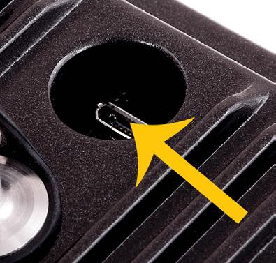
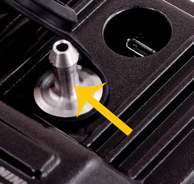
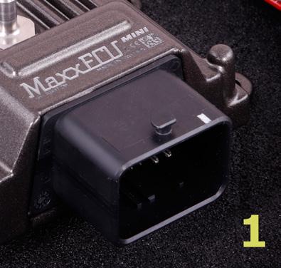
5 ECU overview USB communication ports. MINI, microusb. STREET/SPORT/RACE, USB type B. RACE H2O/PRO USB mini type B. (USB cables always included in kits). Built-in MAP sensor, 3 bar/43.5 psi of boost MINI Uses a regular hose fitting. STREET/SPORT/RACE/PRO Push the MAP connector to secure. To remove, press on the lock ring and pull out. MaxxECU connectors MINI STREET/SPORT RACE PRO
")
, away from excessive")


6 ECU installation STREET/SPORT/RACE units must be mounted inside the vehicle (not waterproofed) MINI/RACE H2O/PRO units can be mounted in the engine bay (waterproofed), away from excessive heat, and the connectors must always face downwards. Example of a MaxxECU PRO installation. Wiring - A proper wiring job is important to get a reliable vehicle Example of a finished engine harness. Use a firewall bushing to prevent damage to the cables. Use shrink tubing with adhesive when splicing cables. Engine ground wire - Very important! The ECU Engine ground wire must ALWAYS be connected to cylinder head Engine must ALWAYS be grounded to the chassis Battery negative (-) must ALWAYS be connected to chassis
.")
 The CLT sensor should be mounted in the engine block/head where the water flow will not be affected by the thermostat.")
7 Inputs Intake air temperature sensor (IAT) This sensor is optional, although highly recommended especially for forced induction engines. The sensor should be mounted in the intake manifold or intake pipes (after the intercooler for forced induction engines). Use a temperature sensor with an exposed sensing element (faster response time) for forced induction engines. Coolant temperature sensor (CLT) The CLT sensor should be mounted in the engine block/head where the water flow will not be affected by the thermostat. The sensor should never be mounted on the radiator or the coolant hoses. Throttle position sensor (TPS) The TPS should be mounted on the actual throttle body, and output a linear signal all the way from closed to fully open. Almost all newer and aftermarket sensors do this, but if your throttle body and TPS are very old or have high mileage you should consider replacing them, as a clean signal is important to get a smooth-running engine. E-Throttle installation? --> maxxecu.com/support Lambda sensor (WBO) All MaxxECU units have built-in wideband controller(s). Supports Bosch LSU 4.2 and 4.9. External wideband electronics can be connected to MaxxECU 0-5V analog inputs (AIN) channels. Make sure the correct type of sensor is selected in MTune before connecting the sensor, otherwise the sensor WILL be damaged. Never connect or disconnect the sensor with the power on. Don t forget to calibrate sensors, Inputs --> Sensors (CLT, IAT, TPS) MAP-sensor All MaxxECU units have a built-in MAP sensor, up to 3 bar/43.5 psi of boost. An external MAP sensor can be connected to MaxxECU 0-5V analog input (AIN) channels if more boost pressure is expected. Analog inputs (AINx) Used for temperature and pressure sensors or other 0-5V position sensors. Inputs --> AIN. Digital inputs (DINx) Can be used to control MaxxECU functions, such as start logging, launch control activation, anti-lag enabling, shift-cut, speed sensor, boost selection, nitrous activation etc. Inputs --> Digital inputs. Inputs marked VR can also be connected directly to VR-sensors such as ABS-wheel speed sensors. Exhaust gas temperature sensors (EGT) MaxxECU RACE and PRO have built-in EGT amplifiers connected to the wiring harness. Inputs --> EGT sensors. Use only good quality EGT sensors and special type K/N thermocouple cable and connectors.


. Diagnostics --> Trigger oscilloscope.")

8 Trigger sensor A trigger sensor must be connected to MaxxECU to read engine RPM. Home/CAM sensor A home/cam sensor must be fitted to run engines sequentially. MaxxECU has a built-in trigger oscilloscope for easy fault diagnostics and examination of trigger signals. Here, a VR sensor connected to TRIGGER (blue line) and a digital sensor connected to HOME (red line). Diagnostics --> Trigger oscilloscope. Two digital inputs connected to TRIGGER and HOME. Diagnostics --> Trigger oscilloscope. Using the built-in trigger logger, connected signals can be examined and sent to us for implemantions of new trigger types.. Diagnostics --> Trigger logger. Trigger problem? --> maxxecu.com/support
9 Outputs Ignition (IGN) Must be connected directly to an ignition module or to a coil with built-in amplifiers, wired to the engine in cylinder order. Coils without built-in drivers MUST be connected via external ignition modules. It is highly recommended to disconnect all ignition-related products during ECU configuration. MaxxECU ignition outputs produce a +5V signal to control ignition modules. Some ignition boxes designed to be triggered from ground (MSD for example), must be connected to GPOs instead. Injection (INJ) All injectors should be wired to the engine in cylinder order. Do not connect low impedance injectors to MINI/STREET without a power resistor, failing to do so will result in damage. MaxxECU grounds the INJ outputs to open the injector, Unused injector outputs can also be used as general-purpose outputs (grounding). MaxxECU MINI/STREET is designed to be used with high impedance injectors only. Injector impedance can be checked by using a multimeter. Greater than 8 ohms --> High impedance injectors. Lower than 8 ohms --> Low impedance injectors --> external power resistors (~4.7ohm) MUST be fitted in series with injectors. MaxxECU SPORT/RACE/PRO is designed to work with both high and low impedance injectors (no external resistors needed). General Purpose Outputs (GPO) GPOs are capable of closing the circuit to GND or producing a pulsed waveform with varying duty cycle and/or frequency. Some GPOs are marked +12V and are therefore able to provide a direct output of +12V instead of ground. Motor outputs/e-throttle (H-bridge) When output is off/disabled, the output is grounded. When output is on/activated, the output is +12V. Wiring problem? --> maxxecu.com/support
 it and following the on-screen instructions.")

. Calibrate the TPS at 0% and 100% throttle opening positions. Select the CLT and IAT sensors.")

10 Engine start After installing the MTune PC-software, connect the included USB-cable and power up the ECU. To get started faster, please visit maxxecu.com/downloads and download a suitable base tune. Load the file into the MaxxECU by opening (yellow icon to the left) it and following the on-screen instructions. Go through the tabs in MTune and do a basic setup for your engine. The settings you most likely want to adjust, are listed below: The number of cylinders, firing order, engine volume. Configuration --> Engine settings. Dwell of ignition coils. Ignition --> Ignition settings. Correct ignition systems. Ignition --> Ignition settings. Correct fuel injector and fuel type. Fuel --> Fuel Inj General. The type of trigger system. Inputs --> Trigger / Home inputs. TPS calibration. Inputs --> Sensors (CLT, IAT, TPS). Calibrate the TPS at 0% and 100% throttle opening positions. Select the CLT and IAT sensors. Check their values in the RealTime Data tab in the lower part of MTune. Please note that TPS values is pedal position when using E-Throttle. E-Throttle help --> maxxecu.com/support Configure all outputs according to your wiring set-up. Outputs --> Output config. Use the test output button feature to test certain outputs to ensure correct wiring. Diagnostics --> Output test to test injectors and coils without cranking the engine. Please note that outputs need to be activated as injector/coil to be able to use the test feature.


11 In order to crank the engine WITHOUT trying to start the engine, use the built-in feature Disable fuel and ignition in Inputs --> Trigger/HOME inputs, Trigger angle. (Please re-enable when subsequently attempting to start the engine) Start cranking, check trigger polarity, adjust timing with an ignition timing lamp. Diagnostics --> Trigger oscilloscope - Built-in tool to see actual trigger inputs. Diagnostics --> Trigger logger - Built-in tool to see the actual time between each trigger input. Inputs --> Trigger, Trigger angle, Lock ignition - Feature to lock ignition advance to sync timing. When all inputs/outputs are configured and engine settings, trigger systems and ignition are synced, it is time to try to start the engine. Engine start problems? --> maxxecu.com/support

12 Thank you for using MaxxECU! You as a customer is our most valued asset Be a tuning mastermind. Like us.
ELITE 1000/1500 Dodge SRT QUICK START GUIDE HT
 E N G I N E M A N A G E M E N T S Y S T E M S ELITE 1000/1500 Dodge SRT4 03-05 QUICK START GUIDE HT-140940 LIMITED WARRANTY Lockin Pty Ltd trading as Haltech warrants the HaltechTM Programmable Fuel Injection
PLATINUM. Sport Haltech 13B Terminated Engine Harness QUICK START GUIDE
 PLATINUM Sport 1000 Haltech 13B Terminated Engine Harness QUICK START GUIDE HALTECH HEAD OFFICE: PH: +612 9729 0999 FAX: +612 9729 0900 EMAIL: sales@haltech.com HALTECH US OFFICE: EMAIL: usa@haltech.com
PLATINUM Sport Haltech GM LS1 / LS6 Terminated Engine Harness (HT045650) QUICK START GUIDE
 QUICK START GUIDE") PLATINUM Sport 2000 Haltech GM LS1 / LS6 Terminated Engine Harness (HT045650) QUICK START GUIDE LIMITED WARRANTY Lockin Pty Ltd trading as Haltech warrants the Haltech TM Programmable Fuel Injection System
PLATINUM Sport 2000 Haltech GM LS1 / LS6 Terminated Engine Harness (HT045650) QUICK START GUIDE LIMITED WARRANTY Lockin Pty Ltd trading as Haltech warrants the Haltech TM Programmable Fuel Injection System
PLATINUM SERIES. Haltech. High Power Igniter Module QUICK START GUIDE. 4 Channel - # HT Channel - # HT Channel - # HT020040
 PLATINUM SERIES Haltech High Power Igniter Module QUICK START GUIDE 4 Channel - # HT020032 6 Channel - # HT020036 8 Channel - # HT020040 HALTECH HEAD OFFICE: PH: +612 9729 0999 FAX: +612 9729 0900 EMAIL:
PLATINUM PRO PLUG-IN HONDA CIVIC (EP3)
") PLATINUM PRO PLUG-IN HONDA CIVIC (EP3) 2002-2005 (HT055047) QUICK START GUIDE HALTECH HEAD OFFICE: PH: +612 9729 0999 FAX: +612 9729 0900 EMAIL: sales@haltech.com HALTECH US OFFICE: EMAIL: usa@haltech.com
PLATINUM PRO PLUG-IN HONDA CIVIC (EP3) 2002-2005 (HT055047) QUICK START GUIDE HALTECH HEAD OFFICE: PH: +612 9729 0999 FAX: +612 9729 0900 EMAIL: sales@haltech.com HALTECH US OFFICE: EMAIL: usa@haltech.com
PLATINUM PRO PLUG-IN Nissan Z32 300ZX
 PLATINUM PRO PLUG-IN Nissan Z32 300ZX (HT-055107) QUICK START GUIDE HALTECH HEAD OFFICE: PH: +612 9729 0999 FAX: +612 9729 0900 EMAIL: sales@haltech.com HALTECH US OFFICE: EMAIL: usa@haltech.com See the
PLATINUM Series CAN WIDEBAND CONTROLLER WBC 1 & WBC 2 QUICK START GUIDE (HT & HT059980) Version 4
 Version 4") PLATINUM Series CAN WIDEBAND CONTROLLER WBC 1 & WBC 2 (HT059970 & HT059980) QUICK START GUIDE HALTECH HEAD OFFICE: PH: +612 9729 0999 FAX: +612 9729 0900 EMAIL: sales@haltech.com HALTECH US OFFICE: PH:
PLATINUM Series CAN WIDEBAND CONTROLLER WBC 1 & WBC 2 (HT059970 & HT059980) QUICK START GUIDE HALTECH HEAD OFFICE: PH: +612 9729 0999 FAX: +612 9729 0900 EMAIL: sales@haltech.com HALTECH US OFFICE: PH:
PLATINUM SPORT GM (HT051100) QUICK START GUIDE. Version
 QUICK START GUIDE. Version") PLATINUM SPORT GM (HT051100) QUICK START GUIDE HALTECH HEAD OFFICE: PH: +612 9729 0999 FAX: +612 9729 0900 EMAIL: sales@haltech.com HALTECH US OFFICE: EMAIL: usa@haltech.com See the Haltech Website for
PLATINUM SPORT GM (HT051100) QUICK START GUIDE HALTECH HEAD OFFICE: PH: +612 9729 0999 FAX: +612 9729 0900 EMAIL: sales@haltech.com HALTECH US OFFICE: EMAIL: usa@haltech.com See the Haltech Website for
PLATINUM PRO PLUG-IN Nissan Z32 300ZX
 PLATINUM PRO PLUG-IN Nissan Z32 300ZX (HT-055107) QUICK START GUIDE LIMITED WARRANTY Lockin Pty Ltd trading as Haltech warrants the Haltech TM Programmable Fuel Injection System to be free from defects
PLATINUM Series Haltech
 PLATINUM Series Haltech Thermocouple Amplifier TCA 2 (HT059920 / HT059921) ( A / B ) TCA 4 (HT059940 / HT059921) ( A / B ) QUICK START GUIDE LIMITED WARRANTY Lockin Pty Ltd trading as Haltech warrants
Quick Start Guide. This is only a quick start guide. A full wiring and installation manual is included in PCLink.
 Quick Start Guide This is only a quick start guide. A full wiring and installation manual is included in PCLink. Installer I/O Table Wire Description Installer Connection Typical Application +14V Bat Full
1. Index. LS Wiring Harness. 2. Presentation Warnings and Warranty Terms Overview Labels...7
 OWNER S MANUAL 1. Index 2. Presentation...4 3. Warnings and Warranty Terms...5 4. Overview...6 5. Labels...7 6. Diagrams...7 6.1 FT500/FT500 Aux - Inputs/outputs...7 6.2 Nano WB O2 #1...8 6.3 Nano WB
MSD 6LS-2 Ignition Controller for Carbureted and EFI LS 2/LS 7 Engines PN 6012
 MSD 6LS-2 Ignition Controller for Carbureted and EFI LS 2/LS 7 Engines PN 6012 ONLINE PRODUCT REGISTRATION: Register your MSD product online. Registering your product will help if there is ever a warranty
1. Index. PRO600 Wiring Harness. 2. Presentation Warnings and Warranty Terms Overview PRO600 Harness...6
 OWNER S MANUAL 1. Index 2. Presentation...4 3. Warnings and Warranty Terms...5 4. Overview...6 4.1 PRO600 Harness...6 5. Versions and components...7 5.1 PRO600 components...7 6. Labels...8 7. Diagrams...9
INSTALLATION INSTRUCTIONS. Revision 4.0.3
 INSTALLATION INSTRUCTIONS Revision 4.0.3 Table of Contents INTRODUCTION... 3 INSTALLATION OVERVIEW... 4 Included Parts... 5 DEVICE WIRING... 6 Required Parts... 6 Guidelines... 6 Wiring Diagram... 7 Engine
MegaSquirt III for Gen 3 HEMI. Hardware Install THE FOLLOWING SENSOR PART NUMBERS APPLY TO ALL HARNESSES FOR ENGINES 2004 TO CURRENT:
 MegaSquirt III for Gen 3 HEMI MegaSquirt controllers are experimental devices intended for educational purposes. MegaSquirt controllers are not for sale or use on pollution controlled vehicles. Check the
Syvecs S6 GP. Syvecs Limited. Pinouts and Wiring Info. Ryan Griffiths
 1 Syvecs Limited Syvecs S6 GP Pinouts and Wiring Info Ryan Griffiths 24 10 2011 This document intended for use by a technical audience and describes a number of procedures that are potentially hazardous.
INSTALLATION INSTRUCTIONS. Revision 3.1.1
 INSTALLATION INSTRUCTIONS Revision 3.1.1 Table of Contents INTRODUCTION... 4 INSTALLATION OVERVIEW... 5 Included Parts... 6 DEVICE WIRING... 7 Required Parts... 7 Guidelines... 7 Wiring Diagram... 8 Compatible
Installation Instructions for: EMS P/N Eclipse Turbo, Talon Tsi, Laser RS Galant VR4
 Installation Instructions for: EMS P/N 30-6300 1990-1994 Eclipse Turbo, Talon Tsi, Laser RS Galant VR4 Thank you for purchasing an AEM Engine Management System. The AEM Engine Management System (EMS) is
MSD 6-Mod Controller for Carbureted and EFI Gen III Engines PN 6011
 MSD 6-Mod Controller for Carbureted and EFI Gen III Engines PN 6011 ONLINE PRODUCT REGISTRATION: Register your MSD product online. Registering your product will help if there is ever a warranty issue with
MegaSquirt III for LS Style Engines. Hardware Install. 1. Disconnect and remove the battery from the vehicle.
 MegaSquirt III for LS Style Engines MegaSquirt controllers are experimental devices intended for educational purposes. MegaSquirt controllers are not for sale or use on pollution controlled vehicles. Check
DFS-1000 Wiring Diagrams and PC Software Installation.
 DFS-1000 Wiring Diagrams and PC Software Installation. For Technical Support Please contact your dealer or email seellc@mchsi.com 1 Important Information - When using a conventional style ignition coil
Installation Instructions for: EMS P/N Mitsubishi 3000GT VR Dodge Stealth TT
 Installation Instructions for: EMS P/N 30-6311 1991-97 Mitsubishi 3000GT VR4 1991-1997 Dodge Stealth TT! WARNING: This installation is not for the tuning novice nor the PC illiterate! Use this system with
Installation Instructions for: EMS P/N Eclipse Turbo, Talon Tsi, Laser RS Galant VR4
 Installation Instructions for: EMS P/N 30-6300 1990-1994 Eclipse Turbo, Talon Tsi, Laser RS Galant VR4! WARNING: This installation is not for the tuning novice nor the PC illiterate! Use this system with
MSD Boost Control Module PN 7763
 MSD Boost Control Module PN 7763 ONLINE PRODUCT REGISTRATION: Register your MSD product online. Registering your product will help if there is ever a warranty issue with your product and helps the MSD
MSD LS-1/LS-6 Controller for Carbureted and EFI Gen III Engines PN 6010
 MSD LS-1/LS-6 Controller for Carbureted and EFI Gen III Engines PN 6010 Parts Included 1 Ignition Controller, PN 6010 1 Pro-Data+ Software CD 1 Harness 1 Parts Bag 6 Timing Modules Optional Accessories
MSD 6-Mod Controller for Carbureted and EFI Gen III Engines PN 6011
 MSD 6-Mod Controller for Carbureted and EFI Gen III Engines PN 6011 Parts Included 1 - Ignition Controller, PN 6011 1 - Pro-Data+ Software CD 1 - Harness 1 - Parts Bag 1-2-Bar MAP Sensor Optional Accessories
Installation Instructions for: EMS P/N and U Honda S2000
 Installation Instructions for: EMS P/N 30-1052 and 30-1052U 00-04 Honda S2000! WARNING: This installation is not for the tuning novice nor the PC illiterate! Use this system with EXTREME caution! The AEM
MSD Circle Track LS Ignition Control PN 6014CT
 MSD Circle Track LS Ignition Control PN 6014CT ONLINE PRODUCT REGISTRATION: Register your MSD product online. Registering your product will help if there is ever a warranty issue with your product and
Installation Instructions for: EMS P/N Toyota MR2 Turbo Toyota Celica All Trac
 Installation Instructions for: EMS P/N 30-1120 1991-1992 Toyota MR2 Turbo 1990-1992 Toyota Celica All Trac! WARNING: This installation is not for the tuning novice nor the PC illiterate! Use this system
Quick Start Guide. This is only a quick start guide. A full wiring and installation manual is included in PCLink.
 Quick Start Guide This is only a quick start guide. A full wiring and installation manual is included in PCLink. Installer I/O Table Wire Description Installer Connection Typical Application Trigger 1
MSD 6-Hemi Controller for Carbureted and EFI Hemi Engines PN 6013
 MSD 6-Hemi Controller for Carbureted and EFI Hemi Engines PN 6013 Parts Included: 1 - Ignition Controller, PN 6013 1 - Pro-Data+ Software CD 1 - Parts Bag 1 - Mounting Template Optional Accessories: Hand
Quick Start Guide. This is only a quick start guide. A full wiring and installation manual is included in PCLink.
 Quick Start Guide This is only a quick start guide. A full wiring and installation manual is included in PCLink. Installer I/O Table Wire Description Installer Connection Typical Application Trigger 1
MSD Single Cylinder Programmable Ignition PN 4217
 MSD Single Cylinder Programmable Ignition PN 4217 Parts Included: 1 - PN 4217 1 - PN 4217 Wire Harness 1 - CD Rom 9609 1 - Parts Bag 1 - Serial Cable WARNING: During installation, disconnect the battery
Products Kronenburg Management Systems. kms.vankronenburg.nl
 Products 2011 Kronenburg Management Systems kms.vankronenburg.nl Kronenburg Management Systems (KMS) is a complete line of engine management systems that offers you an extremely reliable and user-friendly
Installation Instructions for: EMS P/N Ford Mustang 5.0L
 Installation Instructions for: EMS P/N 30-1400 1986-93 Ford Mustang 5.0L! WARNING: This installation is not for the tuning novice nor the PC illiterate! Use this system with EXTREME caution! The AEM EMS
AUTRONIC SM3 ECU Specifications
 AUTRONIC SM3 ECU Specifications Microcomputer Power Supply - Voltage Normal operation Operational limits Intel 16 bit 20MHz 12v to 15v DC 6.2v to 18v DC continuous Power Supply - Current Survival limits
Engine Management and Data Acquisition Systems
 Engine Management and Data Acquisition Systems In 2013 FuelTech celebrates ten years of innovative success and, although young, it has become a synonym of quality high performance. The company was created
Installation Instructions for: EMS P/N Acura Integra Acura 2.3CL Honda Accord Honda Civic
 ! Installation Instructions for: EMS P/N 30-1010 00-01 Acura Integra 98-99 Acura 2.3CL 98-02 Honda Accord 99-00 Honda Civic WARNING: This installation is not for the tuning novice nor the PC illiterate!
MFI Pro - Instructional Manual (Toyota 1uzfe) Version 06.01
 Version 06.01") Tel: 011 3971953 - Fax: 011 3978197 - info@gotech.co.za www.got e ch.c o.za MFI Pro - Instructional Manual (Toyota 1uzfe) Version 06.01 Index: Introduction 1 Before You Begin 1 Basic Tools Required 2 Basic
Tel: 011 3971953 - Fax: 011 3978197 - info@gotech.co.za www.got e ch.c o.za MFI Pro - Instructional Manual (Toyota 1uzfe) Version 06.01 Index: Introduction 1 Before You Begin 1 Basic Tools Required 2 Basic
Lingenfelter ECSS-001 Ethanol Content Sensor Signal Simulator Installation & Operating Instructions
 Lingenfelter ECSS-001 Ethanol Content Sensor Signal Simulator Installation & Operating Instructions PN: L460350085 Revision - 1.6 Lingenfelter Performance Engineering 1557 Winchester Road Decatur, IN 46733
AiM Infotech. Link G4 CAN Bus Base and CAN 500k Bus Base protocol. Release 1.02
 AiM Infotech Link G4 CAN Bus Base and CAN 500k Bus Base protocol Release 1.02 1 Prerequisites This tutorial explains how to connect Link G4 to AiM devices. Link G4 features a bus communication protocol
MSD Boost Control Module PN 77631
 MSD Boost Control Module PN 77631 ONLINE PRODUCT REGISTRATION: Register your MSD product online. Registering your product will help if there is ever a warranty issue with your product and helps the MSD
INSTALLATION INSTRUCTIONS THERMOCOUPLE EXPANSION MODULE
 INSTALLATION INSTRUCTIONS THERMOCOUPLE EXPANSION MODULE 2650-1846-77 Rev. B Details: Temperature Rating: -40 C to 85 C/-40 F to 185 F Vibration Specification: 20 g continuous, 50 g shock Inputs: o 4 EGT
Installation Instructions for: EMS P/N Acura Integra Acura 2.3CL Honda Accord Honda Civic
 Installation Instructions for: EMS P/N 30-6050 00-01 Acura Integra 98-99 Acura 2.3CL 98-02 Honda Accord 99-00 Honda Civic Thank you for purchasing an AEM Engine Management System. The AEM Engine Management
Installation Instructions for: EMS P/N Silvia S13 SR20DET Nissan 180SX SR20DET
 Installation Instructions for: EMS P/N 30-6601 1991-1993 Silvia S13 SR20DET 1991-1995 Nissan 180SX SR20DET! WARNING: This installation is not for the tuning novice nor the PC illiterate! Use this system
Installation Instructions for: EMS P/N Ford Mustang 5.0L
 Installation Instructions for: EMS P/N 30-1401 1994-95 Ford Mustang 5.0L! WARNING: This installation is not for the tuning novice nor the PC illiterate! Use this system with EXTREME caution! The AEM EMS
MAXIMIZER-II Progressive Nitrous Controller INSTALLATION AND USER MANUAL. MAXIMIZER-II rev A
 MAXIMIZER-II Progressive Nitrous Controller INSTALLATION AND USER MANUAL i Table of Contents Page 1. Installation Overview...1 1.1 MAXIMIZER-II Power Input...1 1.2 SOLENOID DRIVER Ground...1 1.3 Arming
Installation Instructions for: EMS P/N Honda S2000
 Installation Instructions for: EMS P/N 30-6052 2000-2005 Honda S2000! WARNING: This installation is not for the tuning novice nor the PC illiterate! Use this system with EXTREME caution! The AEM EMS System
Ford EV6 Injector Adapter Harness User Manual
 Ford EV6 Injector Adapter Harness User Manual 30-3805- THIS PRODUCT IS LEGAL IN CALIFORNIA FOR RACING VEHICLES ONLY AND SHOULD NEVER BE USED ON PUBLIC HIGHWAYS. AEM Performance Electronics AEM Performance
MSD SB6 Programmable Ignition for the Kawasaki ZX-14 PN 4219
 INSTALLATION INSTRUCTIONS MSD SB6 Programmable Ignition for the Kawasaki ZX-14 PN 4219 Parts Included: 1 - Ignition 1 - Wiring Harness 1 - Parts Bag 1 - CD ROM WARNING: When installing the SB6, disconnect
AIM Infotech. ViPec V44-V88 CAN Bus Base and CAN Bus Full protocol. Release 1.00
 AIM Infotech ViPec V44-V88 CAN Bus Base and CAN Bus Full protocol Release 1.00 This tutorial explains how to connect ViPec V44-V88 to AIM loggers using the CAN Bus. This communication protocol offers two
Installation Instructions for: EMS P/N Toyota Supra
 Installation Instructions for: EMS P/N 30-1130 1989-1992 Toyota Supra! WARNING: This installation is not for the tuning novice nor the PC illiterate! Use this system with EXTREME caution! The AEM EMS System
MSD Coil Power Booster for Ford 4.6L/5.4L Mod Motors 99-On PN 8740
 MSD Coil Power Booster for Ford 4.6L/5.4L Mod Motors 99-On PN 8740 ONLINE PRODUCT REGISTRATION: Register your MSD product online. Registering your product will help if there is ever a warranty issued with
MS3-Pro LSx Drop On Harness
 24x MS3-Pro LSx Drop On Harness For engines with 24X crank triggers Thank you for buying our drop on wiring harness! We have designed this harness to support anything from a stock motor swapped into a
Speed-Pro EFI Installation Manual
 Speed-Pro EFI Installation Manual Speed-Pro Electronics Installation Manual Page The wiring harness is labeled on each of the connectors to simplify installation. Your application may not require the use
Controller Ground (dual black 12awg) should be connected to chassis ground as close as possible to the battery.
 should be connected to chassis ground as close as possible to the battery.") 1. Overview The Maximizer 4 progressive nitrous controller operates one or two separate stages of nitrous based on either time, RPM, MPH, throttle percentage or boost pressure. Whether your engine is naturally
1. Overview The Maximizer 4 progressive nitrous controller operates one or two separate stages of nitrous based on either time, RPM, MPH, throttle percentage or boost pressure. Whether your engine is naturally
BMWLink - BMW E36 M50TUB25
 - BMW E36 M50TUB25 Product Warranty Statement LINK ENGINE MANAGEMENT LTD LIMITED LIFETIME WARRANTY All Engine Control Units (ECUs) manufactured or distributed by Link Engine Management Ltd are subject
MSD Pro-Billet Chevrolet HEI Distributor PN 83651, PN 8365/83653
 MSD Pro-Billet Chevrolet HEI Distributor PN 83651, PN 8365/83653 ONLINE PRODUCT REGISTRATION: Register your MSD product online. Registering your product will help if there is ever a warranty issue with
Installation Instructions for: EMS P/N Acura Integra Acura 2.3CL Honda Accord Honda Civic
 Installation Instructions for: EMS P/N 30-6050 00-01 Acura Integra 98-99 Acura 2.3CL 98-02 Honda Accord 99-00 Honda Civic! WARNING: This installation is not for the tuning novice nor the PC illiterate!
SimMotor User Manual Small Engine Simulator and HIL V COPY RIGHTS ECOTRONS LLC All rights reserved
 V2.3.1 SimMotor User Manual Small Engine Simulator and HIL V2.3.1 COPY RIGHTS ECOTRONS LLC All rights reserved Http://www.ecotrons.com Table of Contents Read before you start:...1 Why do I need SimMotor?...2
FAST XIM. XIM Unit Installation
 1 INSTRUCTIONS XIM Thank you for choosing products; we are proud to be your manufacturer of choice. Please read this instruction sheet carefully before beginning installation, and also take a moment to
MSD-8 Plus Ignition PN 7805
 MSD-8 Plus Ignition PN 7805 Note: Solid Core spark plug wires cannot be used with an MSD Ignition. Parts Included: 1 - MSD-8 Plus Ignition 1 - Mag Pickup Extension Harness, PN 8860 4 - Vibration Mounts
RC Engine-EFI. Installation Manual
 RC Engine-EFI RC Engine Electronic Fuel Injection -- Conversion Kit For 120cc to 300cc engines Installation Manual ECOTRONS V1.2.3 http://www.ecotrons.com/ COPY RIGHTS ECOTRONS LLC ALL RIGHTS RESERVED
MSD Blaster Ignition PN 5900
 MSD Blaster Ignition PN 5900 Note: Read these instructions completely before attempting any installation. Parts Included: 1 - Blaster Ignition, PN 5900 1 - Harness, PN 8860 1 - Harness, PN 8861 1-18" Ground
Lamborghini Huracan Kit
 Lamborghini Huracan Kit Thank you for choosing the Syvecs Huracan kit The kit comes with the following: 1 x Syvecs S12 Ecu 1 x GDI12 Driver 1 x Wiring Loom Installation 1.) Remove the Negative Terminal
SCHNITZ MOTORSPORTS USER MANUAL AND INSTALLATION GUIDE PRO-MOD BATTERY VOLTS DIAGNOSTICS NOS PULSE FREQUENCY NOS DELAY TIME IN SECONDS
 SCHNITZ MOTORSPORTS DSC-CS "PRO-MOD" IGNITION CONTROLLER USER MANUAL AND INSTALLATION GUIDE COIL, (OPTIONAL) GA YELLOW, COIL, NEGATIVE GA WHITE, GA BLACK, SHIFT LIGHT +V OUTPUT PAGE 0 NOS ACTIVATION INPUT
GM Throttle Body Adapter Harness User Manual
 GM Throttle Body Adapter Harness User Manual 30-3809-01 THIS PRODUCT IS LEGAL IN CALIFORNIA FOR RACING VEHICLES ONLY AND SHOULD NEVER BE USED ON PUBLIC HIGHWAYS. AEM Performance Electronics AEM Performance
PLUG & PLAY. Quick Start Guide. GM LS 58X Drop On Harness. MS3Pro ULTIMATE
 Quick Start Guide PLUG & PLAY GM LS 58X Drop On Harness MS3Pro ULTIMATE For GM LS Engines with 58X Crank Triggers Thank you for your purchase and support for American made products! We have designed this
KMS MD35 Communication protocol Release 1.02 KMS MD35 ECU.
 KMS MD35 ECU 1 INTRODUCTION AIM has developed special applications for many of the most popular ECUs: by special applications we mean user-friendly systems which allow to easily connect your ECU to our
Subaru MY07 - MY15 STi/WRX Plug-in Manual
 Subaru MY07 - MY15 STi/WRX Plug-in Manual February 2016 Table of Contents 1.0 Introduction... 3 2.0 Expansion Loom... 4 3.0 ECU Channel Assignments... 5 4.0 Plug-in Specific Information... 8 4.1 Fuel Model...
Instruction Manual. P/N Suzuki GSXR1300 Hayabusa 6 Speed Plug & Play Adapter Harness
 Instruction Manual P/N 30-3550 2002-2007 Suzuki GSXR1300 Hayabusa 6 Speed Plug & Play Adapter Harness OVERVIEW The 30-3550 AEM Infinity Adapter Kit was designed for the 2002 2007 Suzuki GSXR1300 Hayabusa.
Universal Gauge User Manual v1.0
 Universal Gauge User Manual v1.0 For gauge hardware revision 4, software version 7 www.perfecttuning.net 1 December 2016 Table of content Table of content... 2 Warning... 4 1 Wiring... 4 1.1 Black 8 conductor
MSD Start/Retard Control PN 8982
 MSD Start/Retard Control PN 8982 IMPORTANT: Read the instructions before attempting installation. Parts Included: 1 - Start/Retard Control, PN 8982 4 - Retard Modules, 0, 2, 3, 4 1 - Wiring Kit 4 - Mounting
User and Installation Manual
 User and Installation Manual PE-ECU-1 Engine Control System Revision I, 3/25/2005 For Software Versions 2.051 Copyright 2005, Performance Electronics, Ltd. All Rights Reserved Legal Disclaimer The products
Setup Tabs. Basic Setup: Advanced Setup:
 Setup Tabs Basic Setup: Password This option sets a password that MUST be entered to re-enter the system. Note: ProEFI can NOT get you into the calibration if you lose this password. You will have to reflash
PSB-1 User Manual. Warning!
 PSB-1 User Manual Warning! The Oxygen Sensor used in this device gets very hot in operation. Do not touch a hot sensor. Do not let a hot sensor touch a combustible surface. Do not use the sensor with or
WIRING MANUAL & DIAGRAMS 199R10555
 WIRING MANUAL & DIAGRAMS 199R10555 HP EFI and Dominator EFI Systems Contents 1.0 Manual Overview... 2 1 1.1 Important Wiring Do s and Don ts... 3 2.0 ECU Installation, Connectors, and Pinout... 3 2.1 Pinout...
MSD 7AL-3, Ignition Control PN 7230
 MSD 7AL-3, Ignition Control PN 7230 Important: Read the instructions before attempting the installation. Parts Included: 1-7AL-3, PN 7230 1 - Parts bag (wires and connectors) 4 - RPM Modules 3000, 7000,
MSD-8 Plus Ignition PN 7805
 MSD-8 Plus Ignition PN 7805 ONLINE PRODUCT REGISTRATION: Register your MSD product online. Registering your product will help if there is ever a warranty issue with your product and helps the MSD R&D team
Ford Focus via OBDII Connection
 Ford Focus via OBDII Connection INTRODUCTION AIM has developed special applications for many of the most common ECUs: by special applications we mean user-friendly systems which allow to easily connect
MSD LS Ignition Control PN 6014/60143
 MSD LS Ignition Control PN 6014/60143 ONLINE PRODUCT REGISTRATION: Register your MSD product online. Registering your product will help if there is ever a warranty issue with your product and helps the
MFI Pro - Instructional Manual Version 05.01
 58 Graniet Street, Jet Park, JHB - Tel: 0 397953 - Fax: 0 397897 www.got e ch.c o.za MFI Pro - Instructional Manual Version 05.0 Index: Introduction Before You Begin Basic Tools Required 2 Basic Components
Dual Fire Capacitor Discharge Ignition
 Dual Fire Capacitor Discharge Ignition Page 1 Dual Fire CDI Instruction Manual VERSION 1.0 Warning Please ensure all power supplies are disconnected before commencing work. This product produces high voltages.
Installation Instructions for: EMS P/N Acura NSX
 Installation Instructions for: EMS P/N 30-1042 1991-94 Acura NSX! WARNING: This installation is not for the tuning novice nor the PC illiterate! Use this system with EXTREME caution! The AEM EMS System
MSD Stacker-4 (4-Channel), PN 7010 Stacker-8 (8-Channel), PN 7020
, PN 7010 Stacker-8 (8-Channel), PN 7020") INSTALLATION INSTRUCTIONS 1 MSD Stacker-4 (4-Channel), PN 7010 Stacker-8 (8-Channel), PN 7020 Important: Read these instructions before attempting this installation! Parts Included: 1 - MSD Stacker Ignition
INSTALLATION INSTRUCTIONS 1 MSD Stacker-4 (4-Channel), PN 7010 Stacker-8 (8-Channel), PN 7020 Important: Read these instructions before attempting this installation! Parts Included: 1 - MSD Stacker Ignition
Mini Flying Lead Harness for Infinity-6/8h STOP! THIS PRODUCT HAS LEGAL RESTRICTIONS. READ THIS BEFORE INSTALLING/USING!
 Instruction Manual 30-3706 Mini Flying Lead Harness for Infinity-6/8h STOP! THIS PRODUCT HAS LEGAL RESTRICTIONS. READ THIS BEFORE INSTALLING/USING! THIS PRODUCT MAY BE USED SOLELY ON VEHICLES USED IN SANCTIONED
Adaptronic esel020 Select ECU for Nissan S13 240SX (KA24DE) / RNN14 GTiR / SR20VE
 / RNN14 GTiR / SR20VE") 1 P a g e Adaptronic esel020 Select ECU for Nissan S13 240SX (KA24DE) / RNN14 GTiR / SR20VE Applicable vehicles / engines: Nissan S13 KA24DE 240SX US Market Nissan N14 SR20DET / SR20VE - Pulsar GTi-R /
1 P a g e Adaptronic esel020 Select ECU for Nissan S13 240SX (KA24DE) / RNN14 GTiR / SR20VE Applicable vehicles / engines: Nissan S13 KA24DE 240SX US Market Nissan N14 SR20DET / SR20VE - Pulsar GTi-R /
10 Ch Peak & Hold Injector Driver PN
 Installation Instructions 10 Ch Peak & Hold Injector Driver PN 30-2710 WARNING: installation is not for the electrically challenged! Use this product with extreme caution! If you are uncomfortable with
PERTRONIX DIGITAL HP INSTALLATION INSTRUCTIONS
 PERTRONIX DIGITAL HP INSTALLATION INSTRUCTIONS TABLE OF CONTENTS Specifications... 4 General Information... 5 Coil Compatibility... 6 Mounting the Digital HP... 7 Wiring... 8 User Interface... 12 Programming...
This product is legal in California for racing vehicles only and should never be used on public highways.
 Installation Instructions for: EMS P/N 30-1602 and 30-1602U 96-99 Nissan 180SX SR20DET 97-98 Nissan Silvia S14 SR20DET 93-98 Nissan Silvia S14 SR20DET (Europe) 99-02 Nissan Silvia S15 SR20DET! WARNING:
P/N Nissan Silvia SR20DET AEM Infinity PnP Harness STOP! THIS PRODUCT HAS LEGAL RESTRICTIONS. READ THIS BEFORE INSTALLING/USING!
 Instruction Manual 1994-1996 Nissan Silvia SR20DET AEM Infinity PnP Harness STOP! THIS PRODUCT HAS LEGAL RESTRICTIONS. READ THIS BEFORE INSTALLING/USING! THIS PRODUCT MAY BE USED SOLELY ON VEHICLES USED
GM Stepper Idle Adapter User Manual
 GM Stepper Idle Adapter User Manual 30-3805-07 THIS PRODUCT IS LEGAL IN CALIFORNIA FOR RACING VEHICLES ONLY AND SHOULD NEVER BE USED ON PUBLIC HIGHWAYS. AEM Performance Electronics AEM Performance Electronics,
MSD Pro-Billet Chevrolet HEI Distributor PN 8365
 MSD Pro-Billet Chevrolet HEI Distributor PN 8365 ONLINE PRODUCT REGISTRATION: Register your MSD product online and you ll be entered in our monthly 8.5mm Super Conductor Spark Plug Wire give-away! Registering
Engine Control Unit. (ECU) Technical Spec ECOTRONS LLC COPY RIGHTS ECOTRONS ALL RIGHTS RESERVED
 Technical Spec ECOTRONS LLC COPY RIGHTS ECOTRONS ALL RIGHTS RESERVED") Engine Control Unit (ECU) Technical Spec ECOTRONS LLC COPY RIGHTS ECOTRONS ALL RIGHTS RESERVED Note: If you are not sure about any specific details, please contact us at info@ecotrons.com. Product: Type:
Engine Control Unit (ECU) Technical Spec ECOTRONS LLC COPY RIGHTS ECOTRONS ALL RIGHTS RESERVED Note: If you are not sure about any specific details, please contact us at info@ecotrons.com. Product: Type:
CPi. CoiL PACK IGNiTioN FOR AViATiON. For 4,6 and 8 cylinder 4 stroke applications. Please read the entire manual before beginning installation.
 1 CPi CoiL PACK IGNiTioN FOR AViATiON Coil pack (4 cylinder) Coil pack (6 cylinder) For 4,6 and 8 cylinder 4 stroke applications. Please read the entire manual before beginning installation. Software version
The Aftermarket EFI buyer s guide, courtesy of
 The Aftermarket EFI buyer s guide, courtesy of www.efisupply.com We often receive inquiries from customers asking which aftermarket electronic fuel injection system is the best one. Rather than steering
Thank you for your purchase Off-ROad NOtice: PROduct WaRNiNgs:
 Thank you for your purchase. Please, read the instructions and watch the video before installing the JMS Progressive N20 Controller. Configuration and installation videos are available online: www.jms-nos.com.
3-Stage Retard PN 8970
 3-Stage Retard PN 8970 IMPORTANT: Read the instructions before attempting the installation. Parts Included: 1-3-Stage Retard Control 4 - Mounting Screws 4 - Mounting Grommets 6 - Retard Modules, 2, 3,
Installation Instructions for the Lingenfelter TBRC-001 Temperature Based Relay Controller
 Installation Instructions for the Lingenfelter PN: L460220000 Lingenfelter Performance Engineering 1557 Winchester Road Decatur, IN 46733 (260) 724-2552 (260) 724-8761 fax www.lingenfelter.com Revision