Table of Contents. Introduction Features of the UEGO UEGO 2000 Components 1. Installation Wideband Oxygen Sensor 2 Driver Box 2 Display Head 4
|
|
|
- Charlotte Little
- 6 years ago
- Views:
Transcription
1
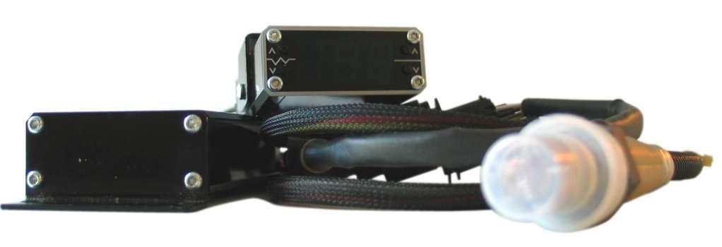
2 Table of Contents Introduction Features of the UEGO UEGO 2000 Components 1 Installation Wideband Oxygen Sensor 2 Driver Box 2 Display Head 4 Display Head Operation Description 5 Display Mode 5 Playback Mode 6 Setup Mode 8 Tach Playback 9 Driver Box Description 10 Operation 10 Using Outputs for Closed Loop Fuel Control 11 Appendix A 12 RPM Divider Chart

3 Introduction Features of the UEGO 2000 The UEGO 2000 is a state-of-the-art product for sensing the engine s air/fuel ratio. It is comprised of three main components: the wideband oxygen sensor, the sensor driver box, and a display head featuring a large, easy to read.56 inch LED display. The UEGO can be used to control a closed-loop fuel injection system without the display head if desired, but the sensor driver must be used. Both the sensor driver and the display head are housed in aluminum extrusion housings appropriate for rigors or the automotive environment. The UEGO 2000 oxygen sensor driver box produces a linear output voltage from.5 to 5 volts proportional to the air/fuel ratio of the exhaust gas that its sensor is reading. The display head converts this voltage signal to a real time display and can log it for later review. The logging feature of the display head allows up to 5 minutes of recording air/fuel and RPM data for playback without the need for a laptop computer or any additional hardware. In addition to the linear.5 to 5 volt wide band output signal which can be used with other data logging systems or engine management systems, the driver box also offers a 0 to.9 volt output for narrow band oxygen sensor applications. The UEGO 2000 narrow band output offers not only a standard 14.7:1 switch point, but also the ability to adjust the switch point (.5v) from 10:1 to 17:1 as described in the driver box operation section. UEGO 2000 Components Display Head Driver Box Wideband Oxygen Sensor 1
4 Installation Installing the Wideband Oxygen Sensor The wideband oxygen sensor is mounted in the exhaust system in front of any catalytic converters and after any turbochargers; if the engine was originally equipped with an oxygen sensor, this location may be used. If installing the wideband oxygen sensor as a supplemental sensor, or on an engine/exhaust system not originally equipped with an oxygen sensor, it should be located between 18 inches (450 mm) and 36 inches (900 mm) from the exhaust valves. The sensor will work any place in the exhaust, but the farther it is from the exhaust ports, the slower it will respond (however, it should never be mounted closer than 12 inches (300 mm) from an exhaust port). If the engine is equipped with individual exhaust runners (headers), the sensor should be mounted in the collector. When selecting the location for the sensor, keep in mind that it should be mounted as vertically as possible (i.e. the tip of the sensor, the part in the exhaust stream, should always be lower than the body (outside of the exhaust), and in an area that won t be submerged or subjected to direct water spray. If mounting in an existing sensor location: 1. Remove the original oxygen sensor. 2. Install the wideband oxygen sensor, using a small amount of anti-seize compound on the threads (it may already be applied from the sensor manufacturer). Be careful NOT to get any anti-seize compound on the sensor s tip area. If mounting the sensor in a new location you will need an 18mm x 1.5 threaded bushing. This is available from EFI Systems, Inc., or you may be able to purchase it locally. Then: 1. Drill an 18mm hole in the exhaust system at the location selected. 2. Weld the threaded boss to the exhaust system over the hole. 3. Screw the sensor into the threaded boss using a small amount of anti-seize compound on the threads. Be careful NOT to get any anti-seize compound on the sensor s tip area. 4. Route the oxygen sensor s wiring harness in such a way that it will not come in contact with hot exhaust parts or rub on moving engine components. Keep in mind that it must reach the driver box mounting point. Plug in 6-way connector to driver box once driver box has been installed as described below. Installing the Driver Box 1. Mount the driver box securely in an area with good air circulation. It can be mounted under the hood but should be located as far as possible from any heat source. The driver box cable should point connector end down to prevent water from draining into it. 2
5 2. The driver box requires a switched +12v input, preferably one that is on only when the engine is running, capable of providing 5 amps current. Wiring the driver to a circuit that is on only when the engine is running will prolong sensor life. It is also important that the driver box not be turned off while the engine is running. Wiring should follow diagram below. 4 red = switched +12v input 4 black = driver box ground (good engine ground) green = narrow band output (see page 10) black = narrow band output ground red (WO) = wide band output (to display or ECU) blk (WBG) = wide band ground
6 Installing the Display Head 1. The display head may be mounted anywhere direct sunlight won t strike the face of the display so that it is easy to read. 2. Route the gray cable with the white connector from the driver box through the fire wall and connect it to the display head. 3. Connect the red wire to a +12v switched circuit fused for 3 amps. The orange and yellow wires are used for tachometer input and output. The yellow input wire is where the display head gets the RPM signal that it can display and data log. The optional orange tach output wire can be used to provide a tach output for data log playback, which is described on page 8. See diagrams below. red = +12v switched input gray cable = input from driver box yellow = tach in orange = tach out 4
7 Display Head Operation Description The UEGO 2000 has 3 modes of operation for the display head; display, playback and setup. Each mode has individual features covered in the following sections. The display head consists of a 3-digit numeric display and 4 control buttons: Left Up (Lup), Left Down (Ldwn), Right Up (Rup) and Right Down (Rdwn). These are illustrated below: Lup Ldwn 14.7 Rup Rdown Display Mode Each time the display head is powered up, it will begin in display mode (as illustrated above). After a brief warm-up period, the display will begin to read live air/ fuel ratio data from the oxygen sensor. While in the Display Mode, you can view RPM data (if optional wiring is connected) and start and stop data log recording. Pressing the Ldwn button will change the display to the RPM view. Since the display face uses 3 large digits for easy viewing, RPM is shown with the last (smallest) digit deleted RPM will read 100, 2000 RPM will read 200, etc. RPM View 500 Press Ldwn for RPM view 5000 RPM shown 5
8 To return to live air/fuel ratio view, press the Lup button. To start a data log recording, press both right buttons at the same time (Rup & Rdwn). The display will flicker slightly to indicate that it is recording. Pressing the Left buttons (Lup & Ldwn) at the same time will stop the recording and return the display to regular live display mode. STOP DATA LOG START DATA LOG Playback Mode Playback mode is used to replay or review air/fuel data that has been logged into the UEGO 2000 s memory. To enter Playback Mode, press the Ldwn & Rup buttons at the same time from the display mode screen. Once in Playback mode, the Lup and Ldwn buttons alternate between air/fuel data and RPM data just as they do in Display mode. The Rup button advances the recording by one frame of data, and Rdwn steps back one step. Holding the Rup button for 3 seconds instructs the display to automatically play (autoplay) the entire recording frame by frame for review the decimal point will flash to let you know that the data is playing frame by frame. Autoplay can be stopped by pressing the Rdwn button for 1 second. When the end of the stored data is reached, SP will be displayed on the screen. Holding Rup and Rdwn for 3 seconds will reset the data log to the beginning. The log can then be reviewed as many times as necessary for tuning purposes. Data is stored in the system even with power turned off as long as a new recording has not been started. To return to Display mode, simply press the Ldwn & Rdwn buttons at the same time. The following illustrations show this process step-bystep. Press both Ldwn & Rup to enter Playback mode Ldwn 14.7 Rup Once in Playback mode, Lup & Ldwn alternate between air/fuel and RPM data Lup Ldwn
9 The Rup button advances recording by one frame of data 14.7 Rup Rdwn The Rdwn steps back one step Hold the Rup button 3 seconds to play entire recording Stop autoplay by pressing Rdwn for 1 second SP will be displayed when end of stored data is reached SP Rup Rdwn Hold Rup and Rdwn for 3 seconds to reset data log to the beginning Press Ldwn and Rdwn to return to Display mode Ldwn 14.7 Rdwn 7
10 Setup Mode Setup mode is used to select air/fuel display preference, RPM input signal calibration (1-12 cylinder) and memory overwrite parameters (stop at end of available memory or erase old data and write over with new). To enter setup mode, press the Lup and Rup buttons at the same time. Once in setup mode, the left buttons determine which setup parameter is currently being modified. The right buttons allow changing of the currently displayed parameter. Pressing Lup and Ldwn for 3 seconds returns you to display mode. Use to Lup 14.7 select parameter Ldwn Rup Rdown Use to select options within each parameter Parameter 1 - Display Choice Options - To Display Select Parameter 2 - RPM Input Divider A/F ratio of gasoline 14.7 lambda 1.00 A/F ratio of alcohol 6.40 Options - C.01 - C.12 Allows the user to select the number of input pulses provided by the engine, per engine revolution pulses per revolution available. See Appendix A for common applications. C.01 Parameter 3 - Memory Start/Stop Option Options - SP. or Run SP. sets the display head to stop logging when available memory is full. You will be able to replay the first 5 minutes your data log. Run allows the unit to overwrite the data, pushing out the oldest. This option allows you to replay the last 5 minutes of logging previous to pushing the logging stop buttons. 8 SP.
11 Tach Playback If an optional switch was wired into the tach signal as shown on page 4, the UEGO 2000 can play back the RPM portion of a data log recording on many types of tachometers while displaying logged air/fuel data on the display head. This switch should remain in the tach input position for normal tach operation and data logging. When reviewing logged data, switch to the tach out side so that the logged RPM can be displayed on the tach while air/fuel data from each indicated RPM is shown on the display head.
12 Driver Box Description The UEGO 2000 driver box is used to maintain the temperature of the oxygen sensor and convert the sensor s output to a.5 to 5 volt signal that is normally read by the Display Head and converted to a air/fuel ratio display. This output voltage can also be used by many aftermarket engine management systems to control fuel delivery. The Driver Box also has the ability to provide a narrow band voltage output signal (0-.9volt) as well. A unique feature of the UEGO 2000 is that this signal can be altered so that the narrow band output signal s midpoint (or switch point) of.5 volts can be set to occur at any air/fuel ratio between 10:1 to 17:1. This can be an important feature when using a factory engine management system for racing purposes. The factory ECU will now see.5 volts as whatever air/fuel ratio the UEGO 2000 is set to rather than the standard 14.7:1 output of a narrow band oxygen sensor. This feature should never be used with street driven vehicles that have catalytic converters installed they could possibly overheat and be damaged! Operation For the standard 14.7:1 narrow band output, turn the small white knob or pot on the rear of the driver box to the full counterclockwise position. This should be done with care using a thumbnail or very gently with a pocket screwdriver so as not to damage the internal electronics. To adjust the narrow band output to your desired switch point, turn the UEGO 2000 off, turn the white pot fully clockwise, then turn the UEGO 2000 power back on the UEGO driver box will now show the adjustable narrow band set point on the display head. By turning the pot and watching the display, the switch point can be set to any air/fuel value other than full lean or full rich. The chosen value will be used after the next power up.. 10
13 Using the UEGO 2000 Outputs for Closed Loop Fueling Many engine management or fuel injection systems can use an oxygen sensor input to make small adjustments to their fuel output based on air/fuel ratio measurement in the exhaust systems that accept a 0-.9volt input where the target or switch point is adjusted as described in the preceding paragraph. Connections should be make as such: (see page 3 for driver box plug diagram). For engine management systems that allow a.5-5volt oxygen input, the red and black wideband output wires from the driver box can be tapped into either at the driver box end or display head end for the wideband voltage signal. Most aftermarket engine control systems need to know how the input voltage correlates to actual air/fuel ratio. This is usually done with a table in the system s calibration software (see your specific system s manual for details). The exact voltage to air/fuel ratio is determined by the following expression: Vout (voltage from the UEGO 2000) x = A/F of gasoline For example, 1volt output from the driver box would equal: 1 volt x = 10 or an air/fuel ratio of 10:1 Voltage can be determined from air/fuel as well: (A/F - 8)/2 = volts Therefore: 14.7 would be (14.7-8)/2 = 3.35 volts 11
14 Appendix A RPM Divider Chart Selection Common Applications - RPM Input 1 Most coil-on-plug applications. This is where each cylinder has its own coil that fires once per 2 engine revolutions (4 cycle engines fireonce every 2 revolutions) 2 Wasted spark type ignition systems. For instance, one coil fires 2 cylinders. The coil fires twice per engine cycle or once per engine revolution. Also used for 4 cylinder distributor engines. 3 Ignition system fires three times per revolution. 6 cylinder engines. 4 Most 8 cylinder distributor engines. 4 spark events per engine revolution Engines that have anywhere from 5 to 12 spark events per engine revolution. (12 cylinder engine with distributor would = 6) 12
FAST Ethanol-Methanol Air/Fuel Meter
 INSTRUCTIONS Ethanol-Methanol Air/Fuel Meter Thank you for choosing products; we are proud to be your manufacturer of choice. Please read this instruction sheet carefully before beginning installation,
Installation Instructions for: DT2-AF2 Dual Channel & DT2-AF1 Single Channel Wide Band O2 Sensor Controller for A/F (Lambda) Measurement
 Measurement") Installation Instructions for: DT2-AF2 Dual Channel & DT2-AF1 Single Channel Wide Band O2 Sensor Controller for A/F (Lambda) Measurement WARNING: This installation is not for the electrically or mechanically
Installation Instructions for: DT2-AF2 Dual Channel & DT2-AF1 Single Channel Wide Band O2 Sensor Controller for A/F (Lambda) Measurement WARNING: This installation is not for the electrically or mechanically
CAUTION: CAREFULLY READ INSTRUCTIONS BEFORE PROCEEDING
 Daytona Sensors LLC Engine Controls and Instrumentation Systems Installation Instructions for Wide-Band Exhaust Gas Oxygen Sensor Interface CAUTION: CAREFULLY READ INSTRUCTIONS BEFORE PROCEEDING OVERVIEW
CAUTION: CAREFULLY READ INSTRUCTIONS BEFORE PROCEEDING
 Daytona Sensors LLC Engine Controls and Instrumentation Systems Installation Instructions for WEGO II Wide-Band Exhaust Gas Oxygen Sensor Interface Methanol Version CAUTION: CAREFULLY READ INSTRUCTIONS
INSTALLATION GUIDE. Dynojet Research 2191 Mendenhall Drive Suite 105, North Las Vegas NV,
 INSTALLATION GUIDE www.dynojetwb2.com Dynojet Research 2191 Mendenhall Drive Suite 105, North Las Vegas NV, 89081 1-800-992-4993 2008 Dynojet Research, Inc. All Rights Reserved. Wideband 2 Installation
CAUTION: CAREFULLY READ INSTRUCTIONS BEFORE PROCEEDING
 Daytona Sensors LLC Engine Controls and Instrumentation Systems Installation Instructions for Wide-Band Exhaust Gas Oxygen Sensor Interface CAUTION: CAREFULLY READ INSTRUCTIONS BEFORE PROCEEDING OVERVIEW
Innovative Racing Electronics
 FOR IMMEDIATE RELEASE Contact: Dan Rudd Phone: 407.330.9727 FAX: 407.322.8632 E-Mail: sales@mpsracing.com Web: www.mpsracing.com Holley Commander 950 Universal 4 Cylinder Fuel Injection Kit Sanford, Florida,
* NOTE: Legal in California only for racing vehicles which may never be used upon a highway
 Read and understand these instructions BEFORE attempting to install this product. Failure to follow installation instructions and not using the provided hardware may damage the intake tube, throttle body
Digatron s DT-46K Instruction Manual
 Digatron s DT-46K Instruction Manual PLAY PAUSE MAX EVENT FUNCTION POWER EXIT Introduction Congratulations on the purchase of your new DT-46K. The DT-46K is Digatron s small, easy to use, multi-function,
# Traction Control Window Switch
 1 INSTRUCTIONS # 82085 Traction Control Window Switch Thank you for choosing products; we are proud to be your manufacturer of choice. Please read this instruction sheet carefully before beginning installation,
LAMBDA 2 USER MANUAL VPV-Motorracing Electronics
 LAMBDA 2 USER MANUAL 2012 VPV-Motorracing Electronics TABLE OF CONTENTS TABLE OF CONTENTS...2 1 TECHNICAL DETAILS...3 1.1 General...3 1.2 Technical specification...4 2 ASSEMBLY...4 2.1 Sensor assembly...4
INSTALLATION INSTRUCTIONS. Revision 3.1.1
 INSTALLATION INSTRUCTIONS Revision 3.1.1 Table of Contents INTRODUCTION... 4 INSTALLATION OVERVIEW... 5 Included Parts... 6 DEVICE WIRING... 7 Required Parts... 7 Guidelines... 7 Wiring Diagram... 8 Compatible
Installation Instructions for NS No Sensor Gauge-Type UEGO Controller
 Installation Instructions for 30-4110NS No Sensor Gauge-Type UEGO Controller WARNING: This installation is not for the electrically or mechanically challenged! Use this sensor with EXTREME caution! If
CAUTION: CAREFULLY READ INSTRUCTIONS BEFORE PROCEEDING
 Twin Tec Installation Instructions for Wide-Band Exhaust Gas Oxygen Sensor System CAUTION: CAREFULLY READ INSTRUCTIONS BEFORE PROCEEDING OVERVIEW The is a complete air/fuel ratio (AFR) metering system
Installation _ + INSTALLATION GUIDE. 12V Ignition Switch. Good Engine Ground. Data Logger Output. Wide Open Throttle Switch (for WOT peak function)
") INSTALLATION GUIDE 52mm WIDE BAND air/fuel ratio monitor 2650-1294-00 Installation 1. Disconnect vehicle battery before installation. 2. Mount gauge in 52.4mm diameter hole. Secure with supplied bracket
INSTALLATION GUIDE 52mm WIDE BAND air/fuel ratio monitor 2650-1294-00 Installation 1. Disconnect vehicle battery before installation. 2. Mount gauge in 52.4mm diameter hole. Secure with supplied bracket
PLATINUM Series CAN WIDEBAND CONTROLLER WBC 1 & WBC 2 QUICK START GUIDE (HT & HT059980) Version 4
 Version 4") PLATINUM Series CAN WIDEBAND CONTROLLER WBC 1 & WBC 2 (HT059970 & HT059980) QUICK START GUIDE HALTECH HEAD OFFICE: PH: +612 9729 0999 FAX: +612 9729 0900 EMAIL: sales@haltech.com HALTECH US OFFICE: PH:
PLATINUM Series CAN WIDEBAND CONTROLLER WBC 1 & WBC 2 (HT059970 & HT059980) QUICK START GUIDE HALTECH HEAD OFFICE: PH: +612 9729 0999 FAX: +612 9729 0900 EMAIL: sales@haltech.com HALTECH US OFFICE: PH:
MALLORY FIRESTORM CD MULTI COIL HARDWARE INSTALLATION - PN 69050S / 69050R
 FORM 69050S/R MALLORY FIRESTORM CD MULTI COIL HARDWARE INSTALLATION - PN 69050S / 69050R To ensure you are using the most current instruction sheet, please visit www.malloryfirestorm.com. CAUTION! The
CAUTION: CAREFULLY READ INSTRUCTIONS BEFORE PROCEEDING
 Daytona Sensors LLC Engine Controls and Instrumentation Systems Installation Instructions for Wide-Band Exhaust Gas Oxygen Sensor System CAUTION: CAREFULLY READ INSTRUCTIONS BEFORE PROCEEDING OVERVIEW
Hot Tach Pro Operation Manual. Competition Systems, Inc Vista Terrace Lake Forest, CA (949)
") Hot Tach Pro Operation Manual Competition Systems, Inc. 26806 Vista Terrace Lake Forest, CA 92630 (949) 580-6898 Hot Tach Pro Operation Manual Revsion:4/2000 Hot Tach Pro Operation Manual Revsion:4/2000
Hot Tach Pro Operation Manual Competition Systems, Inc. 26806 Vista Terrace Lake Forest, CA 92630 (949) 580-6898 Hot Tach Pro Operation Manual Revsion:4/2000 Hot Tach Pro Operation Manual Revsion:4/2000
Automotive Application ET01 Software Revision A 12/06
 Automotive Application ET01 Software Revision A 12/06 INTRODUCTION... 2 FUNCTIONAL DESCRIPTION... 3 INSTALLATION... 4 COMPONENT PLACEMENT... 4 PLUMBING AND WIRING... 5 MSBC OPERATION (ET-01)... 14 TIMED
General information - Various makes and models Technical Information : 01
 General information - Various makes and models Technical Information : 01 System: Engine management Lambda sensor general Tec info General System Information: Figure 1 - Lambda sensors The lambda sensor
The Mark V Air/Fuel Controller - Technical Manual -
 Neutronics Enterprises Inc. The Mark V Air/Fuel Controller - Technical Manual - For Technical Information contact: Neutronics Enterprises Inc. 11421 West Bernardo Court. San Diego, CA. 92127 (858) 674-2250
ALM LSU ADV Manual. Accurate Lambda Meter With built-in LED display COPY RIGHTS ECOTRONS LLC ALL RIGHTS RESERVED.
 ALM LSU ADV Manual Accurate Lambda Meter With built-in LED display COPY RIGHTS ECOTRONS LLC ALL RIGHTS RESERVED Http://www.ecotrons.com Note: If you are not sure about any specific details, please contact
MALLORY FIRESTORM CD MULTI COIL HARDWARE INSTALLATION - PN 69150C / 69150R
 FORM 69150C/R MALLORY FIRESTORM CD MULTI COIL HARDWARE INSTALLATION - PN 69150C / 69150R To ensure you are using the most current instruction sheet, please visit www.malloryfirestorm.com. CAUTION! The
GENERAL MOTORS SERVICE PARTS OPERATION 6200 Grand Pointe Drive, Grand Blanc, MI 48439
 LS CIRCLE TRACK IGNITION CONTROLLER 19355863 Ignition Control for Carbureted LS Series Engines (24x Crankshaft Index/1x Camshaft Index, 58x Crankshaft Index/4x Camshaft Index) Parts Included Quantity Ignition
Installation Instructions for Gauge-Type UEGO Controller
 Installation Instructions for 30-4100 Gauge-Type UEGO Controller WARNING: This installation is not for the electrically or mechanically challenged! Use this sensor with EXTREME caution! If you are! uncomfortable
CAUTION: CAREFULLY READ INSTRUCTIONS BEFORE PROCEEDING
 Daytona Sensors LLC Engine Controls and Instrumentation Systems Installation Instructions for WEGO IIID Wide-Band Exhaust Gas Oxygen Sensor Interface (Automotive Version) CAUTION: CAREFULLY READ INSTRUCTIONS
QUICK START GUIDE 199R10546
 QUICK START GUIDE 199R10546 1.0 Overview This contains detailed information on how to use Holley EFI software and perform tuning that is included within the software itself. Once you load the software,
DynoTune Wideband Gauge
 DISPLAY: RED GREEN BLUE DynoTune Wideband Gauge FACE: BLACK WHITE BEZEL: BLACK SILVER PACKAGE: ROUND SQUARE The DynoTune A/F Gauge will display the air/fuel ratio output from the LC-2 Wide- Band controller.
DUAL WIDEBAND AIR/FUEL RATIO GAUGE Product Numbers: GS-W702W_Dual, GS-C702W_Dual, GS-T702W_Dual
 Installation Instructions Tech Support: 856.768.8300 TechSupport@GlowShiftGauges.com DUAL WIDEBAND AIR/FUEL RATIO GAUGE Product Numbers: GS-W702W_Dual, GS-C702W_Dual, GS-T702W_Dual (1) Gauge (2) Controllers
Wide Band EFIE Installation Instructions. Locate the wide band oxygen sensor current wire
 Wide Band EFIE Installation Instructions Install your fuel efficiency device The EFIE is not intended to be a fuel saver by itself. You should install a device that is designed to get more energy out of
Lingenfelter NCC-002 Nitrous Control Center Quick Setup Guide
 Introduction: Lingenfelter NCC-002 Nitrous Control Center Quick Setup Guide The NCC-002 is capable of controlling two stages of progressive nitrous and fuel. If the NCC-002 is configured only for nitrous,
SLC Pure Plus 2.1 User Manual
 P a g e 1 SLC Pure Plus 2.1 User Manual Caution! The Lambda sensor gets very hot, be careful when handling it. During installation do not insert the Aux 1, Power, and Sensor cables into SLC Pure Plus 2.1,
Using the Gratec Gasoline software
 Using the Gratec Gasoline software The Gratec Software is a sophisticated yet user friendly program in which configures the Gratec CNG or LPG system to perform with your vehicle. Software version 2.002
2011 Yamaha Apex Snowmobile
 PARTS LIST 2011 Yamaha Apex Snowmobile Installation Instructions quantity description 1 power commander 1 USB cable 1 cd-rom 1 installation guide 2 power commander decals 2 dynojet decals 2 velcro strip
30140 F5 Dual Fan Controller
 30140 F5 Dual Fan Controller 1 2501 Ludelle Street Fort Worth, Texas 76105 817-244-6212 Phone 817-244-4024 Fax 888-350-6588 Sales 800-423-9696 Tech E-mail: painless@painlessperformance.com Web: www.painlessperformance.com
COMMANDER Oz AIR/FUEL CONTROL UNIT IMPCO PART EK-CDP-1/EK-CDP-1H Kit INSTALLATION INSTRUCTIONS
 COMMANDER Oz AIR/FUEL CONTROL UNIT IMPCO PART EK-CDP-1/EK-CDP-1H Kit INSTALLATION INSTRUCTIONS INTRODUCTION This document will show you how to install the IMPCO Commander Oz fuel control processor for
Controller Ground (dual black 12awg) should be connected to chassis ground as close as possible to the battery.
 should be connected to chassis ground as close as possible to the battery.") 1. Overview The Maximizer 4 progressive nitrous controller operates one or two separate stages of nitrous based on either time, RPM, MPH, throttle percentage or boost pressure. Whether your engine is naturally
1. Overview The Maximizer 4 progressive nitrous controller operates one or two separate stages of nitrous based on either time, RPM, MPH, throttle percentage or boost pressure. Whether your engine is naturally
Honda VTX1800
 2801191 Rev 06-28-05 User Manual 2002-2005 Honda VTX1800 Part Number DFCM-1 Congratulations on your purchase of this Dynatek product. Please take a moment to read these instructions completely before installing
Installation Guide. Thank you for the purchase of our product. You have just unleashed infinite control, power and ability into your hands.
 Installation Guide Thank you for the purchase of our product. You have just unleashed infinite control, power and ability into your hands. This product is for race use only by experienced engine tuners.
PSB-1 User Manual. Warning!
 PSB-1 User Manual Warning! The Oxygen Sensor used in this device gets very hot in operation. Do not touch a hot sensor. Do not let a hot sensor touch a combustible surface. Do not use the sensor with or
2009 Yamaha Apex Snowmobile
 PARTS LIST 2009 Yamaha Apex Snowmobile Installation Instructions quantity description 1 power commander 1 USB cable 1 cd-rom 1 installation guide 2 power commander decals 2 dynojet decals 2 velcro strip
G - TESTS W/CODES - 2.2L
 G - TESTS W/CODES - 2.2L 1994 Toyota Celica 1994 ENGINE PERFORMANCE Toyota 2.2L Self-Diagnostics Celica INTRODUCTION If no faults were found while performing F - BASIC TESTING, proceed with self-diagnostics.
AS-4000 OPERATING INSTRUCTIONS (PS-5000)
") AS-4000 OPERATING INSTRUCTIONS (PS-5000) BASIC OPERATIONS This unit is a state-of-the-art combination of a vehicle alarm and remote starter system. Start by familiarizing yourself with the alarm functions
AS-4000 OPERATING INSTRUCTIONS (PS-5000) BASIC OPERATIONS This unit is a state-of-the-art combination of a vehicle alarm and remote starter system. Start by familiarizing yourself with the alarm functions
G - TESTS W/CODES Nissan 240SX * PLEASE READ THIS FIRST * INTRODUCTION SELF-DIAGNOSTIC SYSTEM DESCRIPTION HARD FAILURES INTERMITTENT FAILURES
 G - TESTS W/CODES 1990 Nissan 240SX 1990 ENGINE PERFORMANCE Self-Diagnostics Nissan 240SX and Axxess * PLEASE READ THIS FIRST * NOTE: This article has been revised according to Technical Service Bulletin
MSD Pro-Billet Distributor Buick 400, 430, PN 8552 Buick Nailhead - PN 8524
 MSD Pro-Billet Distributor Buick 400, 430, 455 - PN 8552 Buick Nailhead - PN 8524 Important: Read these instructions before attempting the installation. Parts Included: 1 - Pro-Billet Distributor 1 - Rotor,
Tecomotive - tinycwa User Manual
 Tecomotive - tinycwa User Manual Overview Contents - tinycwa controller - Fuse holder - Fuses (15A/30A) - Connector 8 pin (controller) - Connector 4 pin (water pump) - Connector 2 pin (temperature sensor)
Fuel Delivery Requirements
 held Controller the Go EFI System creates a base fuel MAP to get the engine running. Then the self tuning programming will fine tune the MAP to produce optimum power and performance. Through the use of
Optional: Wiring a Relay for Gauge Controlled Output
 Wiring Installation Instructions for : PYROMETER 2 1/16 Spek Pro Professional Racing Gauge GAUGE 12-Pin Wiring Harness & Plug Firewall Grommet DIAGRAM 1 Black-Engine Ground 12-Pin Wiring Harness CUP Coil
Model: AEM14 Analog Engine Monitor
 Model: AEM14 Analog Engine Monitor Installation and Setup Manual Version 1 Table of Contents Monitor Overview DMK Engine Monitor Kit Section 1: Initial Setup 1.1 Internal Settings Switches Figure 1. AEM14
Timing is everything with internal combustion engines By: Bernie Thompson
 Timing is everything with internal combustion engines By: Bernie Thompson As one goes through life, it is said that timing is everything. In the case of the internal combustion engine, this could not be
Fuel Injection. Instruction Manual
 FiTech TM Fuel Injection Instruction Manual for the following Go EFI Systems 30001, 30002, 30004, 30012, 30061, 30062 & 30064 This Quick Start Manual is designed to get you up and running with the Go EFI
IT S ELECTRIC SWITCHING TO HOLLEY EFI YIELDS BETTER DRIVABILITY AND MORE POWER FOR A BOOSTED 68 FIREBIRD
 WORDS: Scott Parker PICTURES: By Redline Motorsports IT S ELECTRIC SWITCHING TO HOLLEY EFI YIELDS BETTER DRIVABILITY AND MORE POWER FOR A BOOSTED 68 FIREBIRD I t s been said many times, and often it has
INSTALLATION GUIDE Table of Contents
 CT-3100 Automatic transmission remote engine starter systems. What s included..2 INSTALLATION GUIDE Table of Contents Door lock toggle mode..... 4 Notice...2 Installation points to remember. 2 Features..2
Instruction Manual. Fuel Injection. for the following Go EFI Systems Go Street EFI System Easy-Street EFI System Kit Contents
 This Quick Start Manual is designed to get you up and running with the Go Street Kit and either the 40003 Fuel Command Center or the 40005 Inline Fuel Delivery Kit. The FiTech Go EFI System is the industry's
CAUTION: CAREFULLY READ INSTRUCTIONS BEFORE PROCEEDING. NOT LEGAL FOR USE OR SALE ON POLLUTION CONTROLLED VEHICLES.
 Twin Tec Installation Instructions for VRFI D Version Fuel Injection Controller CAUTION: CAREFULLY READ INSTRUCTIONS BEFORE PROCEEDING. T LEGAL FOR USE OR SALE ON POLLUTION CONTROLLED VEHICLES. OVERVIEW
GENERAL MOTORS SERVICE PARTS OPERATION 6200 Grand Pointe Drive, Grand Blanc, MI 48439
 LS IGNITION CONTROLLER 19355418 Ignition Control for Carbureted LS Series Engines (24x Crankshaft Index/1x Camshaft Index, 58x Crankshaft Index/4x Camshaft Index) Parts Included Quantity Ignition Controller
Nissan DataScan II User Manual
 Nissan DataScan II User Manual http:\\www.nissandatascan.com Rev. 2 2016 A note to our customers: This software is provided to assist the enthusiast in performing tuning and data collection on the user
COMMANDER Oz AIR/FUEL CONTROL UNIT IMPCO PART EK-CDP-1 INSTALLATION INSTRUCTIONS
 COMMANDER Oz AIR/FUEL CONTROL UNIT IMPCO PART EK-CDP- INSTALLATION INSTRUCTIONS INTRODUCTION This document will show you how to install the IMPCO Commander Oz fuel control processor for industrial engines.
1. Overview. 2. MAX 5 hardware installation
 1. Overview The Maximizer 5 progressive controller operates up to four separate stages of nitrous or water methanol based on either time, RPM, MPH, throttle percentage or boost pressure. Whether your engine
30140 &30142 F5 Dual Fan Controller
 2501 Ludelle Street Fort Worth, Texas 76105 817-244-6212 Phone 817-244-4024 Fax 888-350-6588 Sales 800-423-9696 Tech E-mail: painless@painlessperformance.com Web: www.painlessperformance.com 30140 &30142
Speed-Pro EFI Installation Manual
 Speed-Pro EFI Installation Manual Speed-Pro Electronics Installation Manual Page The wiring harness is labeled on each of the connectors to simplify installation. Your application may not require the use
Tecomotive - tinycwa - User Manual Intercooler Version
 Tecomotive - tinycwa - User Manual Intercooler Version Operation Overview When activated the controller is measuring the coolant temperature and the rate of increase with the connected temperature sensor.
Part Number AEM 4-CH WIDEBAND UEGO CONTROLLER
 Part Number 30-2340 AEM 4-CH WIDEBAND UEGO CONTROLLER FIGURE 1. WIRING DIAGRAM AEM Performance Electronics 2205 126 th Street Unit A, Hawthorne, CA. 90250 Phone: (310) 484-2322 Fax: (310) 484-0152 http://www.aemelectronics.com
Gen III HEMI Harness PN or
 Gen III HEMI Harness PN 558-106 or 558-107 This wiring harness interfaces a Holley EFI ECU to a Gen III HEMI engine. It is meant to be used in conjunction with an injector harness, a coil harness, and
Part Number DP6003 Chevy Truck Digital Dash YEARS 67-72
 Part Number DP6003 Chevy Truck Digital Dash YEARS 67-72 KIT COMPONENTS: One (1) Digital Circuit Board One (1) Smoked Acrylic See-Through Lens *Peel off protective covering from both sides of lens attached
APSX WIDEBAND D2 AFR CONTROLLER GAUGE. Installation and User Manual. APSX WIDEBAND D2 Manual V1.0
 APSX WIDEBAND D2 AFR CONTROLLER GAUGE Installation and User Manual APSX WIDEBAND D2 Manual V1.0 You purchased a wideband gauge! BENCH TEST BEFORE INSTALLING IT! USE A RELIABLE 12V POWER > 5AMP Stock (OEM)ECU
INSTALLATION INSTRUCTIONS PRO PLUS WIDE BAND AIR/FUEL RATIO
 2650-1828-77 Installation 1. Disconnect the negative (-) battery cable. 2. Gauge can be mounted in a 2 1 16 dia. hole with brackets supplied. Gauge can also be mounted in Auto Meter Mounting Cup, or in
MAXIMIZER-II Progressive Nitrous Controller INSTALLATION AND USER MANUAL. MAXIMIZER-II rev A
 MAXIMIZER-II Progressive Nitrous Controller INSTALLATION AND USER MANUAL i Table of Contents Page 1. Installation Overview...1 1.1 MAXIMIZER-II Power Input...1 1.2 SOLENOID DRIVER Ground...1 1.3 Arming
Lambda Control Fuel Adaptation and Fuel Trim
 Lambda Control Fuel Adaptation and Fuel Trim Q: What is Lambda and Lambda Control? A: In the case of a gasoline engine, the optimal mixture of air to fuel for complete combustion is a ratio of 14.7 parts
MAKE OF AUTOMOBILE: TYPE: V 70 PISTON DISPLACEMENT: 2521 NUMBER OF VALVES:
 MAKE OF AUTOMOBILE: TYPE: V 70 PISTON DISPLACEMENT: 2521 NUMBER OF VALVES: 20V ENGINE NUMBER: B5254T TRANSMISSION TYPE ( MT / AT ) AT VEHICLE CATEGORIES M or N PASSENGER CAR ( M ) TYPE VSI INJECTOR (COLOUR
EGT Plus Instructions
 Computech Systems, Inc. 29962 Killpeck Creek Ct. Charlotte Hall, MD 20622 301-884-5712 EGT Plus Instructions The Computech Systems EGT Plus is designed to monitor not only exhaust gas, liquid, tire and
Propane and Gasoline Electronic Fuel Injection
 Zenith Electronic Engine Management System Propane and Gasoline Electronic Fuel Injection 1 Slide 1 2 Slide 2 Home Page System Advantages Block Diagram, Electronic Control Unit Inputs Output Controls System
About the Instructions:
 About the Instructions: The Mass Air Modifier is very easy to install and configure. The print instructions and YouTube videos are very detailed on purpose. This detail is intended to provide you with
AviStart 3000 Installation Manual
 Table of Contents Important Information... 2 Recommended Installation Tools... 2 Recommended Procedures... 2 Main Wiring Diagram... 3 12 Pin Connector... 4 6 Pin Connector... 4 Installation Procedures...5
MFI Pro - Instructional Manual (Toyota 1uzfe) Version 06.01
 Version 06.01") Tel: 011 3971953 - Fax: 011 3978197 - info@gotech.co.za www.got e ch.c o.za MFI Pro - Instructional Manual (Toyota 1uzfe) Version 06.01 Index: Introduction 1 Before You Begin 1 Basic Tools Required 2 Basic
Tel: 011 3971953 - Fax: 011 3978197 - info@gotech.co.za www.got e ch.c o.za MFI Pro - Instructional Manual (Toyota 1uzfe) Version 06.01 Index: Introduction 1 Before You Begin 1 Basic Tools Required 2 Basic
HOWELL INSTALLATION MANUAL. Tuned Port Or LT-1 Fuel Injection Harness ( )
") HOWELL ENGINE DEVELOPMENTS, INC. FUEL INJECTION APPLICATIONS INSTALLATION MANUAL Tuned Port Or LT-1 Fuel Injection Harness (1985-1992) Howell Engine Developments, Inc. 6201 Industrial Way Marine City,
HOWELL ENGINE DEVELOPMENTS, INC. FUEL INJECTION APPLICATIONS INSTALLATION MANUAL Tuned Port Or LT-1 Fuel Injection Harness (1985-1992) Howell Engine Developments, Inc. 6201 Industrial Way Marine City,
Harley Davidson V-Rod Models
 2801190 REV. 8-11-05 User Manual 2002-2005 Harley Davidson V-Rod Models Part Number DFCH-5 Congratulations on your purchase of this Dynatek product. Please take a moment to read these instructions completely
CAUTION: CAREFULLY READ INSTRUCTIONS BEFORE PROCEEDING. NOT LEGAL FOR SALE OR USE IN CALIFORNIA OR ON ANY POLLUTION CONTROLLED VEHICLES.
 Twin Tec VRFI 300 kpa Speed-Density Firmware Tech Note CAUTION: CAREFULLY READ INSTRUCTIONS BEFORE PROCEEDING. NOT LEGAL FOR SALE OR USE IN CALIFORNIA OR ON ANY POLLUTION CONTROLLED VEHICLES. INTRODUCTION
HOWELL INSTALLATION MANUAL. Throttle Body Fuel Injection Harness
 HOWELL ENGINE DEVELOPMENTS, INC. FUEL INJECTION APPLICATIONS INSTALLATION MANUAL Throttle Body Fuel Injection Harness Howell Engine Developments, Inc. 6201 Industrial Way Marine City, MI 48039 Phone: 810-765-5100
Feature Description. Version History
 TA2 Malfunction Indicator Lamp (MIL) and Engine Protection Document Number: FD-0007 Author: J. Goodloe Version: 03 Publish Date: 2016-03-18 Feature Description Version History Version Date Modified Sections
Visit our web site at AMR LS-3000, LS-3010 & LS-3020 BELT SLIP/SEQUENCE CONTROL INSTALLATION AND SETUP INSTRUCTIONS
 AMR INC. DESIGN & MANUFACTURING FOR MINING WORLDWIDE P.O. BOX 234, ROCKY GAP, VA 24366 PHONE (276)928-1712 FAX (276)928-1814 Email sales@americanmineresearch.com Visit our web site at www.americanmineresearch.com
Installation Instructions for Lingenfelter Shift Light Controller with green LED
 Installation Instructions for Lingenfelter Shift Light Controller with green LED PN: L460080000 1557 Winchester Road Decatur, Indiana 46733 260 724 2552 phone 260 724 8761 fax www.lingenfelter.com Parts
ProMax Progressive Controller Installation and Operation Instructions
 ProMax Progressive Controller Installation and Operation Instructions These instructions will guide you through the setup, installation, and use of the Nitrous Outlet Promax Progressive Controller. If
Arctic Cat M8, M1000, F8, and F1000 Snowmobiles
 PARTS LIST 2009-2010 Arctic Cat M8, M1000, F8, and F1000 Snowmobiles Installation Instructions quantity description 1 power commander 1 USB A to mini B cable 1 cd-rom 1 installation guide 2 power commander
DP10001 UNIVERSAL 5 GAUGE DIGITAL PANEL
 Nordskog Performance Products DP10001 UNIVERSAL 5 GAUGE DIGITAL PANEL **Before beginning the installation, read through these instructions thoroughly. Also, disconnect the positive battery cable to avoid
ProECU Mazda MX-5. Live Data Guide 2005-onward Model Year. v1.06
 ProECU Mazda MX-5 Live Data Guide 2005-onward Model Year v1.06 Live Data Live Data Display ProECU Mazda MX-5 can offer real time exceptionally high speed data display and the ability to log this displayed
K10 Intrinsically Safe Electro-Pneumatic Positioner Operating Manual
 K0 Intrinsically Safe Electro-Pneumatic Positioner Operating Manual Pneumatic Connection Outlet Port Gauge Single Acting Actuator (Spring Return): For single acting actuators Outlet Port 2 is to be plugged.
Glossary. 116
 Sequential Fuel Injection Sequential means that each injector for each cylinder is triggered only one time during the engine s cycle. Typically the injector is triggered only during the intake stroke.
WOLF3D. Installation Manual. Version 4.57 Engine Management System with WIDEBAND AFR. Revision Number 1.004
 WOLF3D Version 4.57 Engine Management System with WIDEBAND AFR Installation Manual Revision Number 1.004 Printed January 27, 2016 CONTENTS 1 Introduction... 5 2 ECU... 6 2.1 Mounting the ECU... 6 2.2 Diagnostic
FAST XIM. XIM Unit Installation
 1 INSTRUCTIONS XIM Thank you for choosing products; we are proud to be your manufacturer of choice. Please read this instruction sheet carefully before beginning installation, and also take a moment to
MSD Pro-Billet Chevrolet HEI Distributor PN 83651, PN 8365/83653
 MSD Pro-Billet Chevrolet HEI Distributor PN 83651, PN 8365/83653 ONLINE PRODUCT REGISTRATION: Register your MSD product online. Registering your product will help if there is ever a warranty issue with
DynoTune Wideband Gauge
 DISPLAY: RED GREEN BLUE DynoTune Wideband Gauge FACE: BLACK WHITE BEZEL: BLACK SILVER PACKAGE: ROUND SQUARE The DynoTune A/F Gauge will display the air/fuel ratio output from the LC-1 Wide-Band controller.
AviStart 6500 Installation Manual
 Table of Contents Important Information... 1 Recommended Installation Tools... 1 Recommended Procedures... 1 Main Wiring Diagrams.... 2 Pin Connectors... 5 Installation Procedures...7 Control Unit... 7
Part Number: TDZ-75SD / BRONCO-75SD
 Ford 5.0 EFI Harness Installation Manual For Classic Fords & Mustangs and Early Broncos Part Number: TDZ-75SD / BRONCO-75SD Ron Francis Wiring & The Detail Zone 200 Keystone Rd. Chester, PA 19013 800-292-1940
Ford Coyote Non-VVT Main Harness PN
 Ford Coyote Non-VVT Main Harness PN 558-114 This wiring harness interfaces a Holley EFI ECU to a Ford Coyote engine that has had the cam VVT hardware locked out. It is meant to be used in conjunction with
EFIE Digital Control Panel - Installation Manual
 EFIE Digital Control Panel - Installation Manual HHO Hydrogen on Demand Dual Fuel Generator Systems HHO Plus, Alternative Energies, Ltd Technical Department Travessa das Serras 33, Vieira de Leiria, Portugal
SDS Continental IO-550 Installation Manual
 SDS Continental IO-550 Installation Manual July14/18 This manual covers the steps to install the SDS EM-5 fuel injection and ignition system components on IO-550 engines. Checking Clearance for Hall Sensor
ALM-Inline. Accurate Lambda Meter V1.1.2 COPY RIGHTS ECOTRONS LLC ALL RIGHTS RESERVED.
 ALM-Inline Accurate Lambda Meter V1.1.2 COPY RIGHTS ECOTRONS LLC ALL RIGHTS RESERVED Http://www.ecotrons.com Note: If you are not sure about any specific details, please contact us at info@ecotrons.com.
Technical Sheet on Sprint Tachometers and MSD Ignition Systems. How to Install a Sprint Tachometer With a MSD 6A Ignition System
 Technical Sheet on Sprint Tachometers and MSD Ignition Systems How to Install a Sprint Tachometer With a MSD 6A Ignition System Step 1: Wiring Procedures Sprint Tachometers are voltage-triggered tachometers