Dear Customers. : i MiEV INSTRUMENT PANEL ILLUMINATION INSTALLATION AND HANDLING INSTRUCTIONS. Attention
|
|
|
- Millicent Jacobs
- 5 years ago
- Views:
Transcription
1 Dear Customers Thank you for purchasing a Mitsubishi genuine optional part. For proper use of the product, please read this leaflet thoroughly. It is recommended you keep this leaflet at hand for future reference. i MiEV INSTRUMENT PANEL ILLUMINATION INSTALLATION AND HANDLING INSTRUCTIONS Attention The following symbols are used in this leaflet to arouse caution: WARNING These symbols indicate particularly important safety instructions. Please read and follow them carefully. WARNING This symbol indicates an important safety instruction. Failure to follow it can result in serious bodily injury or even death. This symbol indicates an important safety instruction. Failure to follow it can result in bodily injury or accidents. Failure to follow these instructions not only prevents the product from working properly but may also lead to trouble with the vehicle. Do NOT attempt installation other than instructed in this manual. If you are unsure about installation, handling and/or usage of the product, please consult the Mitsubishi Motors dealer where you purchased the product from. Mitsubishi Motors Corporation is not responsible for any defects or difficulties caused by or resulting from failure to follow given instructions. Part Number Product Name Applicable Model : MZ360381EX : Instrument Panel Illumination : i MiEV Make sure that the customer receives this leaflet to keep at hand. 1 1 S
2 1. Handling Instructions Please read and follow instructions following these symbols WARNING for proper use of the product. Mitsubishi Motors Corporation is not responsible for any defects caused by or resulting from failure to follow given instructions. WARNING If the product gets damaged due to a car accident and such, please discontinue use of the product and replace it with a new one immediately. Please do NOT attempt to alter the product or use it in a way other than specified in this manual. Please make sure that the negative terminal cable is disconnected from the battery during installation work or check-up. Direct gaze into the light may cause sore eye or visual disturbance. Please avoid applying excessive force on the product as it may cause deformation and/or breakage of the product. A Instructions for Use 1) Turn on the small light switch. 2) Wait for Instrument Panel Illumination to light up. * Instrument Panel Illumination lights up/goes off in conjunction with ON/OFF modes of the small light. 2
3 2. Installation Instructions Instructions marked by The symbol WARNING in this leaflet must be observed carefully during installation. indicates an important safety instruction. Do NOT attempt installation other than instructed in this manual. WARNING Do NOT alter or disassemble the product, and always install and/or handle it as instructed in this leaflet. Keep the vehicle parked on the flat, horizontal ground during installation work. Make sure to apply the hand brake securely and take the ignition key out of the key cylinder before installation in order to prevent abrupt movement of the vehicle. Check beforehand that there is no gasoline leakage in the work space, and perform installation work in a well-ventilated area in order to avoid explosion or fire. Keep children and pet animals out of the work space. Their unexpected behavior may lead to a serious accident. Avoid working on a street or in a place that is accessible to any person. Before installation, check the product for transport damage. Discontinue work immediately when you have found damage or dropped the product on the ground. To avoid short-circuit fault of the battery, always pull out the negative terminal cable first when disconnecting cables. Connect the positive terminal cable first when reconnecting cables. Record the memory contents of electrical components (e.g. preset tuning of the radio, etc.) beforehand. Disconnection of a battery cable may result in malfunction of vehicle control systems. Refer to the workshop manual for details. Prevent the positive and the negative terminal cables from simultaneous contact with metal objects to reduce risk of explosion or fire resulting from short-circuit fault. Do NOT let the product interfere with fuel hoses and pipes. Fuel leakage caused by damage to these components may lead to explosion or fire. Do NOT let the product interfere with brake hoses and pipes. The brake system may not operate properly if brake fluid leaks due to interference, which may lead to a serious accident. When routing harnesses, bind them with vehicle wiring harnesses or fix them with cable ties to prevent them from dangling. Attaching harnesses to sharp-edged areas of the vehicle body may cause wire breakage. Take the vehicle for a test drive once it has been confirmed that the engine functions properly after installation of the product. Failure to do so may lead to an accident. Be careful not to touch the engine and its surrounding parts when they are hot. Perform installation/inspection work after the engine compartment has cooled down. Avoid applying excessive force on the product as it may cause deformation and/or breakage of the product. Put on protective gear (e.g. work gloves, workwear, work cap, protective eyeglasses) to avoid a chance of injury during installation work. Keep the negative terminal cable disconnected from the battery during installation work. When cables are connected to/disconnected from the battery, the engine switch and the light switch have to be turned off. Make sure to insert the positive and the negative terminal cables in the proper position. Do NOT attach the product to high pressure pipes (e.g. brake pipes, air conditioner pipes) to avoid malfunction of the vehicle. Keep the product away from hot components (e.g. exhaust manifold) or moving parts (e.g. fan belt, electric fan). When starting the engine during installation work, make sure that no tool or part is left in the engine room and that the shift lever is put in the neutral or parking range to reduce risk of accident. In case harnesses of the product contact an edge of the vehicle panel, wrap them with cushion foam for protection. 3
4 When connecting/disconnecting connectors, make sure to hold on to them and avoid pulling on cables. Damage or rupture of connection may lead to short-circuit fault. When connecting a connector and a terminal, push them against each other until the lock of a connector clicks to keep them from coming apart during use. When installing parts on the vehicle, be careful not to pinch surrounding harnesses in between. Damage or rupture of connection may lead to short-circuit fault. Pulling strongly on wire harnesses may cause connectors/terminals to come off or break. When tightening or loosening bolts and/or nuts, use a tool that matches their size. Use of an unsuitable tool may cause damage to bolts/nuts or insufficient clamping. Tighten each bolt/nut of the product securely with the torque specified in this leaflet. Retighten them if they loosen after test drive. Reinstall removed bolts/nuts securely with the torque specified in the workshop manual. Tightening with unauthorized torque may lead to the engine malfunction. Before applying double-faced adhesive tape, use clean cloth to remove marks and oil thoroughly from the attachment surface. Do NOT use such organic solvents as thinner, benzine and gasoline in this process. Use of isopropyl alcohol or degreaser is recommended. Touching the adhesive surface of double-faced tape with dusty hands or work gloves will significantly deteriorate adhesiveness of the tape and increase risk of disengagement of parts. After installation of the product, check electrical components (e.g. lamps, horn, wipers, audio) for proper operation. Note that this product may not be used in combination with other Mitsubishi genuine optional parts. Make sure to confirm the product s applicability in advance. Instructions for Handling Wiring Harnesses Follow the following instructions carefully in order to perform installation work properly and safely. Make sure to disconnect the negative terminal cable from the battery. * Record the memory contents of electrical components (e.g. preset tuning of the radio). Check electrical components (e.g. lamps, horn, wipers, audio) for proper operation. * Make sure to do post-installation check. When tightening bolts and nuts, use a tool that matches their size. * Keep to the specified torque where provided. When disconnecting connectors, pull on them, not on cables, to unlock. * Pulling on cables may lead to wire breakage. Make sure to connect connectors and/or terminals securely. * Loose fit may lead to poor electrical connection. Fasten harnesses to vehicle wiring harnesses or bind them up with a cable tie to keep them from dangling. Cut When installing parts on the vehicle, be careful not to pinch surrounding harnesses in between. * Damage to harnesses may lead to rupture. Do not pull on wiring harnesses strongly. * Pulling on harnesses may lead to wire breakage or disengagement of connectors. After installation of harnesses, check reinstalled vehicle parts for proper operation. * Post-installation check is important for prevention of faulty wiring. 4
5 AS FITTED DRAWING CONNECTION SCHEMATIC DIAGRAM Instrument Panel Illumination (1) Light Source Connection Connection Connected to Concentrated Earth Earth Terminal Earthing Wire Connected to Junction Box Element Connection Connection Fuse Power Supply Harness (2) 2-pin Connector (5) Branch Harness (3) 5
6 TOOLS Socket Wrench Combination Wrench Torque Wrench Phillips Screwdriver Flat-blade Screwdriver Cutting Pliers Utility Knife Scissors File Masking Tape Primer (*) Isopropyl Alcohol or Degreaser Cloth (*) Used for bonding polypropylene (PP) and acrylic adhesive tape together COMPONENT PARTS 1 Instrument Panel Illumination: 1 2 Power Supply Harness: 1 3 Branch Harness: 1 4 Guide: pin Connector: 1 6 Harness Fastener: 6 7 Cable Tie: 7 8 Foam: 1 9 Fitting/Handling Instructions: 1 Make sure that all necessary components are included in the kit and are free of damage. The illustrations above may appear different from what actual components look like. 6


7 * The name and the shape of the panel to attach the product to may be different depending on the vehicle model. (E.g. Model with the radio/cd player: Radio/CD Player, Model without the radio/cd player: Center Upper Panel) Note that the installation process may differ slightly according to the vehicle model. Although names and illustrations of vehicle parts used in this leaflet are for the model with the radio/cd player, perform the same work on the model without the radio/cd player. A Vehicle Preparation for Installation 1) Refer to the workshop manual and disconnect the negative terminal cable from the battery. To avoid short-circuit fault of the battery, always pull out the negative terminal cable first when disconnecting cables. Connect the positive terminal cable first when reconnecting cables. 2) Refer to the workshop manual and remove the following parts from the vehicle: Under Cover, Cowl Side Trim (LH), Scuff Plate (LH), Column Cover, Meter Panel After removal of the under cover and attaching parts, keep them in a safe place until reused for reinstallation. Meter Panel Column Cover Under Cover Cowl Side Trim 3) 4) Apply masking tape to the instrument panel along the outer periphery of the radio/cd player and the center upper cover. When the Mitsubishi genuine accent panel is installed, apply masking tape along the outer periphery of the accent panel. Refer to the workshop manual and remove the radio/cd player and the center upper cover. As masking tape will be used as a guide for parts installation later, apply it neatly. Center Upper Cover Radio/CD Player Masking Tape A-A Cross Section Radio/CD Player Masking Tape Instrument Panel 7

 Remove the backing sheet off the back of Guide (4). Paste Guide (4) to the instrument panel along the masking tape.")
8 5) Wipe dirt off the inner side of taped area on the instrument panel for degreasing. Then, apply primer to the same area. NOTE Use isopropyl alcohol or degreaser to wipe dirt off. Do NOT use such organic solvents as thinner and gasoline. Lack of degreasing treatment may cause the product to come off. Make sure to apply primer within the taped area. Read primer usage carefully and handle with proper knowledge. Let primer dry after application (for approximately 15 minutes). Masking Tape Apply primer after degreasing treatment. 6) Remove the backing sheet off the back of Guide (4). Paste Guide (4) to the instrument panel along the masking tape. Adhesiveness of double-faced tape deteriorates greatly at a temperature below 15 C. Warm up the working area or the attachment surface to keep the product from falling off. Make sure to crimp double-faced tape on the attachment surface to fix the product securely. Do not touch the adhesive surface of double-faced tape and/or the attachment surface on the vehicle with dusty hands or work gloves. This will significantly deteriorate adhesiveness of the tape and may cause the product to come off. Masking Tape A-A Cross Section Masking Tape Attach tape closely to panel. Instrument Panel 8
, then remove Instrument Panel Illumination (1) from Guide (4).")
.")
9 7) Attach Instrument Panel Illumination (1) to Guide (4). Make sure that the length of the left and right sides is even. Mark the location of seam joint of the radio/cd player on Instrument Panel Illumination (1), then remove Instrument Panel Illumination (1) from Guide (4). The joint section between Instrument Panel Illumination (1) and the harness contains LED inside. Applying excessive force to or pulling on the ends of the joint section may lead to system malfunction or breakage. NOTE Use masking tape when marking on Instrument Panel Illumination (1). Do not write with a permanent marker. Masking Tape Marking Masking Tape Heater Control Panel Assembly 8) Refer to the workshop manual and remove the center lower panel. B Installation of Instrument Panel Illumination 1) Provide cutouts on the center lower panel as illustrated below. Cutout Cutout Center Lower Panel 9
 and upper ends of center lower panel.")
.")

10 2) Align the upper ends of the center lower panel and the marks on Instrument Panel Illumination (1), and insert Instrument Panel Illumination (1) into the groove on the back of the removed center lower panel. Align marks on Instrument Panel Illumination (1) and upper ends of center lower panel. Center Lower Panel 3) Apply primer to Harness Fastener (6) attachment surface, and fix the harness of Instrument Panel Illumination (1) to the center lower panel using Harness Fasteners (6). Read primer usage carefully and handle with proper knowledge. Let primer dry after application (for approximately 15 minutes). Route the harness of Instrument Panel Illumination (1) in a way to avoid interference with the cigar lighter socket, and fix the harness securely with Harness Fasteners (6). Usage of Harness Fastener A: Remove the backing sheet on the back of the base and fix the fastener to the attachment point. B: Lay the harness on the base and bend the holding part of the fastener to fix the harness. Holding Part Base Harness (1) Bend this portion. Harness (1) Harness Fastener (6) Attachment Points of Harness Fastener (6) Center Lower Panel 10
11 4) 5) Install the center lower panel in the reverse order of disinstallation. Remove the locating masking tape and insert Instrument Panel Illumination (1) into Guide (4) attached on the instrument panel. For Models WITH Radio/CD Player 6) Place the radio/cd player temporarily on the vehicle and provide cutouts to where it interferes with Guide (4). Trim the portions specified in the illustration below with a file so that they do not interfere with Instrument Panel Illumination (1). The location of cutouts differs depending on the vehicle model. Check the panel shape prior to installation and provide cutouts at proper locations. Put on protective eyeglasses when working on cutouts in order to avoid a chance of visual disturbance caused by whittlings. Use a file and remove burr finely to keep surrounding harnesses from getting caught. NOTE Carry out the cutout work after removing the center upper panel from the radio/cd player. Make a cutout. Center Upper Cover Make a cutout. Make a cutout. Trim here. Trim here. Trim here. Radio/CD Player For models without the radio/cd player, see the next page. 11
12 For Models WITHOUT Radio/CD Player 6) Place the center upper panel temporarily on the vehicle and provide cutouts to where it interferes with Guide (4). The location of cutouts differs depending on the vehicle model. Check the panel shape prior to installation and provide cutouts at proper locations. Put on protective eyeglasses when working on cutouts in order to avoid a chance of visual disturbance caused by whittlings. Use a file and remove burr finely to keep surrounding harnesses from getting caught. Make a cutout. Make a cutout. Make a cutout. Center Upper Panel C Wiring of Power Supply Harness 1) Insert the flat terminal of Power Supply Harness (2) into 2-pin Connector (5). When connecting/disconnecting connectors, make sure to hold on to them and avoid pulling on cables. Damage or rupture of connection may lead to short-circuit fault. When connecting connectors, push both sides against each other until the lock clicks to keep them from coming apart during use. View in Flat Terminal Insertion Direction Flat Terminal * The flat terminal can be inserted into either Hole 1 or Hole 2 of 2-pin Connector (5). 2) Refer to the connection schematic diagram on Page 5 and connect Power Supply Harness (2) and Branch Harness (3). 12

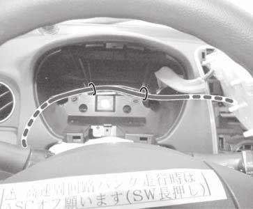
13 3) Connect the connector of Branch Harness (3) to an empty connector on the junction box as indicated in grey below. When connecting/disconnecting connectors, make sure to hold on to them and avoid pulling on cables. Damage or rupture of connection may lead to short-circuit fault. When connecting connectors, push both sides against each other until the lock clicks to keep them from coming apart during use. Connect Branch Harness (3) to this connector. Junction Box 4) 5) Route Power Supply Harness (2) along the existing harness up to the center console. Refer to the illustration below and the detail views and clamp Power Supply Harness (2) temporarily with Cable Ties (7) loosely at fixation points (A to F) on the existing harness. Full tightening of Cable Ties (7) makes it hard to adjust the length of Power Supply Harness (2) in a later step. Detail X Detail Y Detail Z NOTE Keep Cable Ties (7) loosely fixed to the existing harness. In case harness fixation clips are provided on the existing harness, clamp near the clips. Existing Harness Detail W Do not fully tighten Cable Ties (7). This illustration is an outline of fixation points. For details of each point, refer to the detail views. 13


14 Detail View W Detail View X A B Detail View Y Detail View Z C D E F 14
 Adjust the length of Power Supply Harness (2) and tighten loosely-fixed Cable Ties (7) securely to the existing harness.")

15 6) Remove the bolt for the concentrated earth on the junction box and tighten the earth terminal of Power Supply Harness (2) together with the earth using the removed bolt. Concentrated Earth < Arrow View > 7) Adjust the length of Power Supply Harness (2) and tighten loosely-fixed Cable Ties (7) securely to the existing harness. Fix harnesses securely to keep them from dangling and interfering with other parts. When cutting short the tip of a fixed cable tie, keep the remaining portion below 1mm in length so that it will not interfere with surrounding components. 1mm Cut short. 8) Restore Guide (4), installed with Instrument Panel Illumination (1), to the vehicle by sliding its edge into the groove of the radio/cd player and the center upper cover. Radio/CD Player Center Upper Cover A-A Cross Section Radio/CD Player Instrument Panel 15
-wrapped connection with Cable Tie (7). 3) 4) 5) Confirm that all the wiring harnesses are connected properly.")
16 D Operation Check / Wiring Harness Bundling 1) 2) Connect the bullet terminals of Instrument Panel Illumination (1) and of Power Supply Harness (2) together, and wrap Foam (8) around the connection after removing the backing sheet. Fix the Foam (8)-wrapped connection with Cable Tie (7). 3) 4) 5) Confirm that all the wiring harnesses are connected properly. If not, rework on the connection of each section. Connect the negative terminal cable to the battery and check for the lighting condition of Instrument Panel Illumination (1). Restore all the removed parts to their original position. 16
ASX / OUTLANDER SPORT / RVR REAR VIEW CAMERA MZ380552EX INSTALLATION AND HANDLING INSTRUCTIONS
 ASX / OUTLANDER SPORT / RVR REAR VIEW CAMERA MZ380552EX INSTALLATION AND HANDLING INSTRUCTIONS Navigation (MMCS) unit Camera Thank you for purchasing the Mitsubishi Genuine Accessory. To install and use
LANCER FOG LAMP KIT MZ380479EX (for RHD) INSTALLATION AND HANDLING INSTRUCTIONS
 INSTALLATION AND HANDLING INSTRUCTIONS") LANCER FOG LAMP KIT MZ380479EX (for RHD) INSTALLATION AND HANDLING INSTRUCTIONS Fog lamp Thank you for purchasing the Mitsubishi Genuine Accessory. To install and use the product correctly with proper
LANCER FOG LAMP KIT MZ380479EX (for RHD) INSTALLATION AND HANDLING INSTRUCTIONS Fog lamp Thank you for purchasing the Mitsubishi Genuine Accessory. To install and use the product correctly with proper
HARNESS KIT F INSTALLATION INSTRUCTIONS. Vehicle: Mazda RX-8 Parts number F CFZ (ipod integration module) C9F4 V6 029 (Harness Kit F)
 C9F4 V6 029 (Harness Kit F)") GENUINE ipod INTEGRATION MODULE HARNESS KIT F INSTALLATION INSTRUCTIONS Vehicle: Mazda RX-8 Parts numberf197 79 CFZ (ipod integration module) C9F4 V6 029 (Harness Kit F) Thank you for purchasing a genuine
GENUINE ipod INTEGRATION MODULE HARNESS KIT F INSTALLATION INSTRUCTIONS Vehicle: Mazda RX-8 Parts numberf197 79 CFZ (ipod integration module) C9F4 V6 029 (Harness Kit F) Thank you for purchasing a genuine
ASX / OUTLANDER SPORT SHIFT KNOB MZ525507EX INSTALLATION AND HANDLING INSTRUCTIONS
 ASX / OUTLANDER SPORT SHIFT KNOB MZ55507EX INSTALLATION AND HANDLING INSTRUCTIONS Thank you for purchasing the Mitsubishi Genuine Accessory. To install and use the product correctly with proper knowledge
Remote engine start INSTALLATION INSTRUCTIONS
 GENUINE Remote engine start INSTALLATION INSTRUCTIONS Thank you for purchasing a genuine Mazda accessory. efore removal and installation, be sure to thoroughly read these instructions. Please read the
GENUINE Interior Lighting Kit
 GENUINE Interior Lighting Kit INSTALLATION INSTRUCTIONS Thank you for purchasing a genuine Mazda accessory. Before removal and installation, be sure to thoroughly read these instructions. Please read the
Remote engine start INSTALLATION INSTRUCTIONS
 GENUINE Remote engine start INSTALLATION INSTRUCTIONS Thank you for purchasing a genuine Mazda accessory. Before removal and installation, be sure to thoroughly read these instructions. Please read the
INTEGRATION MODULE HARNESS KIT A4, F4
 GENUINE INTEGRATION MODULE HARNESS KIT A4, F4 INSTALLATION INSTRUCTIONS Vehicle: Mazda MX-5 Parts numberbbm2 79 CFZ (ipod integration module) C9FA V6 029 (Harness Kit A4) C9FB V6 029 (Harness Kit F4) Thank
GENUINE Interior Lighting Kit
 GENUINE Interior Lighting Kit INSTALLATION INSTRUCTIONS Thank you for purchasing a genuine Mazda accessory. Before removal and installation, be sure to thoroughly read these instructions. Please read the
TOYOTA COROLLA ILLUMINATED DOOR SILLS Preparation
 Preparation Part Number: PT942-02140 Kit Contents Item # Quantity Reqd. Description 1 1 Illuminated Scuff plate, Front Right Hand 2 1 Illuminated Scuff plate, Front Left Hand 3 1 Door Scuff plate, Rear
LANCER SIDE WIND DEFLECTOR MZ562863EX INSTALLATION AND HANDLING INSTRUCTIONS
 LANCER SIDE WIND DEFLECTOR MZ6863EX INSTALLATION AND HANDLING INSTRUCTIONS Thank you for purchasing the Mitsubishi Genuine Accessory. To install and use the product correctly with proper knowledge of it,
INSTALLATION INSTRUCTIONS
 INSTALLATION INSTRUCTIONS Accessory Application Publications No. ELEMENT AII 24282 Issue Date DEC 2002 PARTS LIST 2 Screw-grommets CD Changer Attachment Kit: P/N 08B26-SCV-100 CD changer plate 2 Self-tapping
SCION tc ILLUMINATED DOOR SILLS Preparation
 Preparation Part Number: PTS21-21070 Kit Contents Item # Quantity Reqd. Description 1 2 Hardware Kit w/ power harness 2 1 Front Left Illuminated Door Sill Protector 3 1 Front Right Illuminated Door Sill
TOYOTA COROLLA ILLUMINATED DOOR SILLS Preparation
 Preparation Part Number: PT942-02140 Kit Contents Item # Quantity Reqd. Description 1 1 Illuminated Scuff plate, Front Right Hand 2 1 Illuminated Scuff plate, Front Left Hand 3 1 Door Scuff plate, Rear
Be sure to carry out the following before starting work
 Be sure to carry out the following before starting work If an older version of the CMU software is being used, the CarPlay/Android Auto-compatible USB hub may not be recognized. If the software version
INSTALLATION INSTRUCTIONS
 INSTALLATION INSTRUCTIONS Accessory Application Publications No. SYSTEM S2000 AII 26324 Issue Date OCT 2004 PARTS LIST Headrest Speaker System P/N 08A54-S2A-100 3 Small wire ties 2 Headrest speakers 9
INSTALLATION INSTRUCTIONS
 INSTALLATION INSTRUCTIONS Accessory LED FOGLIGHT ATTACHMENT KIT P/N 08V70-MKC-A00 Application GL1800/B/BD/D/DA Honda Dealer: Please give a copy of these instructions to your customer. Publication No. MII
INSTALLATION INSTRUCTIONS
 INSTALLATION INSTRUCTIONS Accessory Application Publications No. AII 27996 ATTACHMENT KIT 2005 CIVIC HYBRID Issue Date AUG 2004 PARTS LIST Changer Attachment Kit: P/N 08B26-S5B-100 4 Washer-screws, 4 x
TOYOTA im INTERIOR LIGHT KIT Preparation
 Preparation Part Number: PT922-12170 Kit Contents Item # Quantity Reqd. Description 1 1 Main Wire Harness 2 1 Switch 3 1 Switch Header 4 1 ECU 5 1 ECU Bracket 6 1 Hardware Kit 7 1 Instruction Card 8 1
INSTALLATION INSTRUCTIONS
 INSTALLATION INSTRUCTIONS Accessory Application Publications No. CD CHANGER ATTACHMENT KIT 2005 CIVIC SI AII 27936 Issue Date AUG 2004 PARTS LIST CD Changer Attachment Kit (sold separately): P/N 08B26-S5T-100
INSTALLATION INSTRUCTIONS
 INSTALLATION INSTRUCTIONS Accessory Application Publications No. AII 43458 XM RADIO SYSTEM 2011 RIDGELINE Issue Date JUNE 2010 PARTS LIST 4 Washer-screws, 5 x 8 mm Attachment Kit: P/N 08B15-SJC-100A 2
INSTALLATION INSTRUCTIONS
 INSTALLATION INSTRUCTIONS Accessory Application Publications No. XM RADIO SYSTEM 2009 RIDGELINE AII 40319 Issue Date AUG 2008 PARTS LIST 4 Washer-screws, 5 x 8 mm Attachment Kit: P/N 08B15-SJC-100A 2 XM
INSTALLATION INSTRUCTIONS
 INSTALLATION INSTRUCTIONS Accessory Application Publications No. AII 32459-34084 XM RADIO SYSTEM 2007 RIDGELINE Issue Date NOV 2006 PARTS LIST 4 Washer-screws, 5 x 8 mm Attachment Kit: P/N 08B15-SJC-100A
TOYOTA TACOMA TVIP V5
 Preparation Part Number: PT398-35090 Kit Contents Item # Quantity Reqd. Description 1 1 Wire Harness 2 1 Security ECU 3 1 GBS ECU 4 1 Status Monitor/Microphone 5 2 Warning Labels (English) 6 2 Warning
INSTALLATION INSTRUCTIONS
 INSTALLATION INSTRUCTIONS Accessory Application Publications No. AII 25876 2004 PILOT (LX only) Issue Date AUG 2003 The subwoofer cannot be installed on a vehicle equipped with a navigation unit. Subwoofer
INSTALLATION INSTRUCTIONS
 INSTALLATION INSTRUCTIONS Accessory REMOTE ENGINE STARTER SYSTEM Application 2010 CIVIC 4-DOOR Publications No. AII 42460 Issue Date AUG 2009 PARTS LIST Remote Engine Starter Unit Kit P/N 08E91-E22-100B
Part Number: PT
 Preparation Part Number: PT374-02090 Kit Contents Item # Quantity Reqd. Description 1 1 Auto Dimming Mirror Assembly w/ shift area light 2 1 Hardware bag Hardware Bag Contents Item # Quantity Reqd. Description
TOYOTA Yaris Hatchback EC REARVIEW MIRROR Preparation
 Preparation Part Number: PT374-02090 Kit Contents Item # Quantity Reqd. Description 1 1 Auto Dimming Mirror Assembly w/ shift area light 2 1 Hardware bag Hardware Bag Contents Item # Quantity Reqd. Description
INSTALLATION INSTRUCTIONS
 INSTALLATION INSTRUCTIONS Accessory Application Publications No. AII 32664 TRUNK MOUNT 2007 ACCORD 4-DOOR Issue Date JULY 2006 PARTS LIST 17 Wire ties Attachment Kit (sold separately): P/N 08B26-SDA-100
PRELIMINARY INSTALLATION INSTRUCTIONS. Remote Engine Starter Attachment Kit P/N 08E92-SNA-100B
 INSTALLATION INSTRUCTIONS Accessory Application Publications No. REMOTE ENGINE STARTER SYSTEM 2008 CIVIC 2-DOOR AII 38215 Issue Date OCT 2007 PARTS LIST Remote Engine Starter Unit Kit P/N 08E91-E22-100B
TOYOTA RAV TRAILER WIRE HARNESS Section I Installation Preparation
 Section I Installation Preparation Part Number: 08921-42900 Kit Contents Item # Quantity Reqd. Description 1 1 Converter 2 1 Wire harness 3 1 Sub wire harness No.1 4 2 Plastic Tie (300mm) 5 21 Plastic
INSTALLATION INSTRUCTIONS
 INSTALLATION INSTRUCTIONS Accessory XM RADIO SYSTEM Application 2012 RIDGELINE Publications No. AII 12045 Issue Date NOV 2011 PARTS LIST Attachment Kit: P/N 08B15-SJC-100A 4 Flange nuts, 6 mm 4 Washer-screws,
INSTALLATION INSTRUCTIONS
 INSTALLATION INSTRUCTIONS Accessory Application Publications No. CIVIC AII 24171 S 2- AND 4-DOOR Issue Date (DX, HX) AUG 2002 NOTE: Fog Lights cannot be installed if the vehicle is equipped with an optional
Air filter. Attention
 PAJERO / MONTERO (V60, V70, V80, V90) AIR FILTER (for Air-conditioner) MZ341010EX (for right-hand drive vehicle) MZ341011EX (for left-hand drive vehicle) INSTALLATION AND HANDLING INSTRUCTIONS Air filter
INSTALLATION INSTRUCTIONS
 INSTALLATION INSTRUCTIONS Accessory Application Publications No. CD CHANGER ATTACHMENT KIT 2004 CR-V AII 26118 Issue Date SEP 2003 PARTS LIST CD Changer Attachment Kit (sold separately): P/N 08B26-S9A-100
VENTILATION SYSTEM SECTION VTL CONTENTS VENTILATION, HEATER & AIR CONDITIONER VTL-1 PRECAUTION... 3 PREPARATION... 5 SYSTEM DESCRIPTION...
 VENTILATION, HEATER & AIR CONDITIONER SECTION VTL A VENTILATION SYSTEM B C D CONTENTS E PRECAUTION... 3 PRECAUTIONS... 3 Precaution for Supplemental Restraint System (SRS) "AIR BAG" and "SEAT BELT PRE-TEN-
GENUINE REAR SPOILER
 GENUINE REAR SPOILER IMPORTANT POINTS IN PAINTING PART NAME: REAR SPOILER PART NUMBER: 0000-8Y-H50/GHK1 V4 920/G44B V4 920 VEHICLE: MAZDA6 1 PAINT AREAS SURFACE TREATMENT a : Paint same as body color b
GENUINE SATELLITE RADIO KIT
 GENUINE STELLITE RDIO KIT INSTLLTION INSTRUCTIONS Thank you for purchasing a genuine Mazda accessory. Before removal and installation, be sure to thoroughly read these instructions. Please read the contents
SCION xb EC REARVIEW MIRROR Preparation
 Preparation Part Number: PT374-02090 Kit Contents Item # Quantity Reqd. Description 1 1 AD Mirror Assembly w/ PRNDL 2 1 Hardware bag Hardware Bag Contents Item # Quantity Reqd. Description 1 2 T-tap Connectors,
SCION xb SIRIUS SATELLITE RADIO TUNER Preparation
 Preparation Part Number: PTS3-52050 NOTE: Part number of this accessory may not be the same as the part number shown. Kit Contents Item # Quantity Reqd. Description Antenna, Exterior 2 Wire Harness 3 Bracket,
SCION iq AUDIO Preparation
 Preparation Part Number: PT546-00140 (Base Radio) Kit Contents Item # Quantity Reqd. Description 1 1 Receiver Assembly, Radio Unit 2 1 Hardware Bag Hardware Bag Contents Item # Quantity Reqd. Description
SCION xb AUTO-DIMMING MIRROR Preparation
 Preparation Part Number: PT374-02090 Kit Contents Item # Quantity Reqd. Description 1 1 AD Mirror Assembly w/ PRNDL 2 1 Hardware bag Hardware Bag Contents Item # Quantity Reqd. Description 1 2 T-tap Connectors,
INSTALLATION INSTRUCTIONS
 INSTALLATION INSTRUCTIONS Accessory Application Publications No. CASSETTE/MP3/ AII 30664 2006 ACCORD IN-DASH CD 2- AND 4-DOOR Issue Date ATTACHMENT AUG 2005 PARTS LIST cable Attachment Kit (sold separately):
VENTILATION SYSTEM SECTION VTL CONTENTS VENTILATION, HEATER & AIR CONDITIONER VTL-1 SYSTEM DESCRIPTION... 3 PRECAUTION... 6 PREPARATION...
 VENTILATION, HEATER & AIR CONDITIONER SECTION VTL A VENTILATION SYSTEM B C D CONTENTS E SYSTEM DESCRIPTION... 3 AUTOMATIC AIR CONDITIONER SYSTEM... 3 WITH COLOR DISPLAY...3 WITH COLOR DISPLAY : Switches
GENUINE PARTS INSTALLATION INSTRUCTIONS
 GENUINE PARTS INSTALLATION INSTRUCTIONS 1. 2. 3. 4. DESCRIPTION: Security Light Kit APPLICATION: Altima Coupe and Sedan (2011+) PART NUMBER: 999F4 AX008 - Universal Security Lighting Kit. KIT CONTENTS:
TOYOTA TACOMA EC REARVIEW MIRROR Preparation
 Preparation Part Number: PT374-35052 Kit Contents Item # Quantity Reqd. Description 1 1 AD Mirror Assembly 2 1 Hardware bag Hardware Bag Contents Item # Quantity Reqd. Description 1 1 T-tap Connectors,
INSTALLATION INSTRUCTIONS
 INSTALLATION INSTRUCTIONS Accessory Application Publications No. AII 37978 XM RADIO SYSTEM 2008 CIVIC HYBRID Issue Date SEP 2007 PARTS LIST XM Radio Attachment (sold separately): P/N 08B15-SNA-100B 7 Wire
LEXUS GS 350/450h ILLUMINATED DOOR SILLS Preparation
 Preparation Part Number: PT922-30120 (GS350) PT922-30130 (GS450h) NOTE: Part number of this accessory may not be the same as the part number shown. Kit Contents Item # Quantity Req'd. Description 1 1 Illuminated
TOYOTA COROLLA 2010 TVIP V4 PREPARATION
 PREPARATION Part #: PT398-02080 or PT398-02100 NOTE: Part number of this accessory may not be the same as the part number shown. Conflicts: Do not install into Manual Transmission Vehicles or Vehicles
INSTALLATION INSTRUCTIONS
 Accessory Application Publication No. INSTALLATION INSTRUCTIONS ATTACHMENT P/N 08T70-MGZ-D80 CB500X/XA MII 14565 Issue Date May 2013 PARTS LIST KIT Sold separately (1) (2) (4) (2) (1) (3) BOOT (1 piece.)
INSTALLATION INSTRUCTIONS
 INSTALLATION INSTRUCTIONS Accessory Application Publications No. REMOTE CONTROL 2009 MDX BII 40030 Issue Date JULY 2008 PARTS LIST Remote Engine Starter Unit Kit P/N 08E91-E22-200B Remote Control Engine
INSTALLATION INSTRUCTIONS
 INSTALLATION INSTRUCTIONS Accessory Application Publications No. in- ENTERTAINMENT SYSTEM 2004 TSX BII 24811 Issue Date APRIL 2003 PARTS LIST Attachment Kit P/N 08B23-SDA-101A Monitor bracket harness FM
TOYOTA RAV4 w/smart 2009 TVIP V4 PREPARATION
 PREPARATION Part #: PT398-42110 Conflicts: Do not install into Vehicles manufactured from November 2012 and Onwards. Kit Contents RES ECU Gateway ECU RES ECU Bracket Gateway ECU Bracket Remote Label Key
INSTALLATION INSTRUCTIONS
 INSTALLATION INSTRUCTIONS Accessory Application Publications No. CIVIC All 30175-31616 2 AND 4-DOOR P/N 08E10-SNA-100 Issue Date DEC 2005 NOTE: The interior illumination lights cannot be installed on 2-door
GENUINE PARTS INSTALLATION INSTRUCTIONS
 GENUINE PARTS INSTALLATION INSTRUCTIONS 1. 2. 3. 4. DESCRIPTION: Accent light Kit APPLICATION: Infiniti JX (2013) PART NUMBER: 999F3 YY000 - Universal Accent Lighting Kit. KIT CONTENTS: Item QTY Description
INSTALLATION INSTRUCTIONS
 INSTALLATION INSTRUCTIONS Accessory Application Publications No. S 1998 CIVIC 2/3/4-DOOR All 18767 Issue Date SEP 1997 PARTS LIST Fog Light Kit: P/N 08V31-S01-100 Right fog light (marked R ) Fuse label
INSTALLATION INSTRUCTIONS
 INSTALLATION INSTRUCTIONS Accessory Application Publications No. S CIVIC 2 AND 4-DOOR (EX, LX) AII 24188 Issue Date AUG 2002 NOTE: Fog Lights cannot be installed if the vehicle is equipped with an optional
INSTALLATION INSTRUCTIONS
 INSTALLATION INSTRUCTIONS Accessory Application Publications No. AII 26042-26353 XM INTERFACE ODYSSEY EXCEPT EX-L WITH NAVI/RES Issue Date FEB 2004 PARTS LIST 8 Wire ties XM Radio Attachment P/N 08B15-S0X-100
GENUINE PARKING SENSORS (Rear)
") GENUINE PARKING SENSORS (Rear) INSTALLATION INSTRUCTIONS Thank you for purchasing a genuine Mazda accessory. Before removal and installation, be sure to thoroughly read these instructions. Please read
GENUINE PARKING SENSORS (Rear) INSTALLATION INSTRUCTIONS Thank you for purchasing a genuine Mazda accessory. Before removal and installation, be sure to thoroughly read these instructions. Please read
GENUINE PARTS INSTALLATION INSTRUCTIONS
 GENUINE PARTS INSTALLATION INSTRUCTIONS DESCRIPTION: APPLICATION: PART NUMBER: KIT CONTENTS: Illuminated Kick Plate Maxima (Applicable ONLY to U.S. Market Vehicles with Build Date June 2012 or later) 999G6
 INSTALLATION INSTRUCTIONS Accessory Application Publications No. 2010 CIVIC All 42479 2- AND 4-DOOR P/N 08E10-SNA-110 Issue Date AUG 2009 NOTE: The interior illumination lights cannot be installed on 2-door
INSTALLATION INSTRUCTIONS
 INSTALLATION INSTRUCTIONS Accessory REMOTE CONTROL Application 2012 ODYSSEY (EXCEPT LX) Publications No. AII 46745 Issue Date SEP 2011 PARTS LIST Remote Control Engine Starter Unit Kit P/N 08E91-E22-101A
Cargo Socket Kit. Securely connect connectors and terminals. Failure to do so can result in poor connections.
 00 Cargo Socket Kit Fitting Model OUTBACK October 2014 and later Installation Instructions PART No. H6710AL100 J: To those installing this product Important 1. We recommend that you ask the SUBARU dealer
LANCER EVOLUTION (2008 ) MUD FLAP MZ531356EX (Black with aluminum plate) MZ531357EX (Black standard) INSTALLATION AND HANDLING INSTRUCTIONS
 MUD FLAP MZ531356EX (Black with aluminum plate) MZ531357EX (Black standard) INSTALLATION AND HANDLING INSTRUCTIONS") LANCER EVOLUTION (2008 ) MUD FLAP MZ531356EX (Black with aluminum plate) MZ531357EX (Black standard) INSTALLATION AND HANDLING INSTRUCTIONS Black with aluminum plate -MZ531356EX Black standard -MZ531357EX
LANCER EVOLUTION (2008 ) MUD FLAP MZ531356EX (Black with aluminum plate) MZ531357EX (Black standard) INSTALLATION AND HANDLING INSTRUCTIONS Black with aluminum plate -MZ531356EX Black standard -MZ531357EX
SCION tc Navigation System Preparation. Part Number: PT
 Preparation Part Number: PT611-21111 Kit Contents Item # Quantity Reqd. Description 1 1 Navigation System 2 1 GPS Antenna 3 1 Bluetooth Antenna 4 1 Wire Harness (Reverse / Park Brake) 5 1 RCA Relay Cable
INSTALLATION INSTRUCTIONS
 INSTALLATION INSTRUCTIONS Accessory Application Publications No. XM SATELLITE RADIO SYSTEM (EX) 2008 PILOT All 37110 Issue Date JUN 2007 PARTS LIST XM Radio Attachment (sold separately) P/N 08B15-S9V-100A
TOYOTA COROLLA EC REARVIEW MIRROR Preparation
 Preparation Part Number: PT374-02090 Kit Contents Item # Quantity Reqd. Description 1 1 AD Mirror Assembly w/ PRNDL 2 1 Hardware bag Hardware Bag Contents Item # Quantity Reqd. Description 1 2 T-tap Connectors,
(1) Remote Control with (2) AAA Batteries
 Remote Control with (2) AAA Batteries") TOOLS REQUIRED: KIT CONTENTS: E14 Torx (1) Remote Control with (2) AAA Batteries (2) Wireless Headphones with (4) AAA Batteries (2) DVD Headrest Units Owner s Manual (1) Owner s Manual (1) Power / Audio
TOOLS REQUIRED: KIT CONTENTS: E14 Torx (1) Remote Control with (2) AAA Batteries (2) Wireless Headphones with (4) AAA Batteries (2) DVD Headrest Units Owner s Manual (1) Owner s Manual (1) Power / Audio
GENUINE PARTS INSTALLATION INSTRUCTIONS
 GENUINE PARTS INSTALLATION INSTRUCTIONS 1. 2. 3. 4. DESCRIPTION: Accent light Kit APPLICATION: Versa (2012) PART NUMBER: 999F3 AW008 - Universal Accent Lighting Kit. KIT CONTENTS: Item QTY Description
TOYOTA COROLLA 2009 TVIP V4 PREPARATION
 PREPARATION Part #: PT398-02080 Conflicts: NOTE: Part number of this accessory may not be the same as the part number shown. Do not install into Manual Transmission Vehicles or Vehicles without RKE systems.
INSTALLATION INSTRUCTIONS
 INSTALLATION INSTRUCTIONS Accessory Application Publications No. CD/CASSETTE PLAYER 2005 CIVIC 2- AND 4-DOOR AII 27857 Issue Date AUG 2004 PARTS LIST Cassette Player: P/N 08A53-S5A-100 Cassette player
INSTALLATION INSTRUCTIONS
 INSTALLATION INSTRUCTIONS Accessory REMOTE CONTROL Application 2011 ODYSSEY (EXCEPT LX) Publications No. AII 43923 Issue Date SEP 2010 PARTS LIST Remote Control Engine Starter Unit Kit P/N 08E91-E22-101A
Main Harness Quantity: 1
 Smart Engine Start INSTALLATION MANUAL Genuine Part # : H001SVA900 Vehicle Model : WRX Kit Contents Service P/N: H001SVA910 Service P/N: H001SVA820 NOT USED NOT USED SES ECU Quantity: 1 Double-sided tape
TOYOTA RAV4/HV INTERIOR LIGHT KIT Preparation
 Preparation Part Number: PT413-42130 Kit Contents Item # Quantity Reqd. Description 1 1 Wire Harness 2 3 Hardware Bag Contents Item # Quantity Reqd. Description 1 20 Cable Tie 2 2 Scotchlok 3 2 Foam Pad
TOYOTA TACOMA 2005 TVIP V5 (RS3200 PLUS) Preparation
 Preparation") Preparation Part Number: 08586 04840 Kit Contents Item # Quantity Reqd. Description 1 1 Wire Harness 2 1 Security ECU 3 1 GBS ECU 4 1 Status Monitor 5 2 Warning Labels 6 1 Owner s Manual 7 1 Warranty Card
Preparation Part Number: 08586 04840 Kit Contents Item # Quantity Reqd. Description 1 1 Wire Harness 2 1 Security ECU 3 1 GBS ECU 4 1 Status Monitor 5 2 Warning Labels 6 1 Owner s Manual 7 1 Warranty Card
GENUINE MUD FLAP (FRONT)
") GENUINE MUD FLAP (FRONT) INSTALLATION AND USER S INSTRUCTIONS Thank you for purchasing a Genuine Mazda Accessory. Before removal and installation, be sure to thoroughly read these instructions. Please
GENUINE MUD FLAP (FRONT) INSTALLATION AND USER S INSTRUCTIONS Thank you for purchasing a Genuine Mazda Accessory. Before removal and installation, be sure to thoroughly read these instructions. Please
INSTALLATION INSTRUCTIONS
 INSTALLATION INSTRUCTIONS Accessory Application Publications No. All 27176 2005 CR-V Issue Date P/N 08V31-S9A-114 SEP 2004 PARTS LIST 25 Wire ties Left fog light 6 Washer-bolts Right fog light 6 Spring
INSTALLATION INSTRUCTIONS
 INSTALLATION INSTRUCTIONS Accessory Application Publications No. SYSTEM ACCORD 2-DOOR (LX/EX L4, LX V6) AII 25749 Issue Date FEB 2004 PARTS LIST Double-sided adhesive tape XM Radio Attachment Kit : P/N
GENUINE MUD FLAP (REAR)
") GENUINE MUD FLAP (REAR) INSTALLATION AND USER S INSTRUCTIONS Thank you for purchasing a Genuine Mazda Accessory. Before removal and installation, be sure to thoroughly read these instructions. Please read
GENUINE MUD FLAP (REAR) INSTALLATION AND USER S INSTRUCTIONS Thank you for purchasing a Genuine Mazda Accessory. Before removal and installation, be sure to thoroughly read these instructions. Please read
INSTALLATION INSTRUCTIONS
 INSTALLATION INSTRUCTIONS Accessory REMOTE CONTROL Application 2008 CR-V Publications No. AII 35843-38422 Issue Date DEC 2007 PARTS LIST Caution label Remote Engine Starter Kit P/N 08E91-E22-100B Transmitter
INSTALLATION INSTRUCTIONS
 Accessory Application Publication No. INSTALLATION INSTRUCTIONS HEATED GRIP ATTACHMENT P/N 08T70-MJE-D00 CBR650F/FA MII 14960 Issue Date April 2014 PARTS LIST HEATED GRIP Sold separately (1) (2) (4) (2)
GENUINE PARTS INSTALLATION INSTRUCTIONS
 GENUINE PARTS INSTALLATION INSTRUCTIONS 1. 2. 3. 4. DESCRIPTION: APPLICATION: PART NUMBER: KIT CONTENTS: Accent light Kit Versa Note 999F3 4Z000 - Accent Lighting Kit. 999Q9 AY000 - Accessory Service Connector
GENUINE FOG LIGHT INSTALLATION AND USER S INSTRUCTIONS
 GENUINE FOG LIGHT INSTALLATION AND USER S INSTRUCTIONS Thank you for purchasing a genuine Mazda accessory. Before removal and installation, be sure to thoroughly read these instructions. Please read the
PRELIMINARY INSTALLATION INSTRUCTIONS PARTS LIST. Combination light switch Right fog light. 4 Self-tapping washer-screws.
 INSTALLATION INSTRUCTIONS Accessory S P/N 08V31-SCV-100D Application 2009 ELEMENT (SC) Publications No. AII 40515 Issue Date OCT 2008 PARTS LIST Combination light switch Right fog light Left fog light
INSTALLATION INSTRUCTIONS
 INSTALLATION INSTRUCTIONS Accessory Application Publications No. IN DASH/CASSETTE/ MULTI MEDIA ATTACHMENT KIT 2007 CIVIC 2- and 4-DOOR (DX) AII 33543 Issue Date AUG 2006 NOTE: The vehicle must be equipped
TOYOTA TACOMA TVIP V3 (RS3200) Section I - Installation Preparation
 Section I - Installation Preparation") Section I - Installation Preparation Part Number: 08586-04810 Section I - Installation Preparation Kit Contents Item # Quantity Reqd. Description 1 1 Wire Harness 2 1 Status Monitor 3 1 Piezo Buzzer 4
Section I - Installation Preparation Part Number: 08586-04810 Section I - Installation Preparation Kit Contents Item # Quantity Reqd. Description 1 1 Wire Harness 2 1 Status Monitor 3 1 Piezo Buzzer 4
GENUINE ACCESSORIES INSTALLATION INSTRUCTIONS. ITEM QTY DESCRIPTION Usage Chart Service Part Number. 1 1 Mirror Assembly w/ Compass 1
 AUTO PART NUMBER: 0000 8C P4 (DIO)/ 0000 89 P25 (PIO) REQUIRED COMPONENTS: INSTALLATION KIT: 2 SA Harness - 2 Conductor 3 0 Wire Ties 4 Wire Cover 5 A-Pillar Tether Clip (D09W-6862) 6 3 Foam Tape 7 3 Electro-Tap(wire
INSTALLATION INSTRUCTIONS
 INSTALLATION INSTRUCTIONS Accessory REMOTE CONTROL Application Publications No. 2009 ACCORD AII 39977-40931 4-DOOR Issue Date (A/T ONLY) NOV 2008 PARTS LIST Remote Engine Starter Unit Kit P/N 08E91-E22-100A
AC 110V POWER OUTLET INSTALLATION INSTRUCTIONS. Part No. Application 1. PRE INSTALLATION / INSTALLATION OVERVIEW 2. KIT CONTENTS H7110AJ100
 Part. Application H70AJ00 LEGACY / OUTBACK 0MY w/ HK audio LEGACY / OUTBACK 0MY w/o HK audio AC 0V POWER OUTLET INSTALLATION INSTRUCTIONS Page. -6,9-5 Page. -4,7-5. PRE INSTALLATION / INSTALLATION OVERVIEW
INSTALLATION INSTRUCTIONS
 INSTALLATION INSTRUCTIONS Accessory Application Publications No. AUTOMATIC AII 27160 2005 CR-V Issue Date ATTACHMENT KIT SEP 2004 PARTS LIST Automatic Day/Night Mirror Attachment Kit (sold separately)
INSTALLATION INSTRUCTIONS
 INSTALLATION INSTRUCTIONS Accessory Application Publications No. All 12035 SYSTEM 2012 RIDGELINE Issue Date NOV 2011 PARTS LIST Security System Attachment Kit: P/N 08E55-SJC-101 Flange bolt Unit bracket
INSTALLATION INSTRUCTIONS
 INSTALLATION INSTRUCTIONS Accessory Application Publications No. S P/N 08V31-SHJ-100A 2010 ODYSSEY AII 41829-43750 Issue Date MARCH 2010 PARTS LIST Relay Left fog light 22 Wire ties Right fog light Wire
INSTALLATION INSTRUCTIONS
 INSTALLATION INSTRUCTIONS Accessory Application Publications No. AII 26031 2004 ODYSSEY Issue Date AUG 2003 NOTE: You cannot install the subwoofer in a vehicle equipped with both an under seat Navigation
TOYOTA TACOMA TVIP V5
 Preparation Part Number: PT398-35121 Conflicts Note: Must not be installed in Vehicles with Factory Alarm System and 2013- Vehicles with (4WD Double Cab 6MT and Off-Road Package). Kit Contents Item # Quantity
LEXUS RX 450h 2010 TVIP V4 PREPARATION
 PREPARATION Part #: PT398-48112 Conflicts: Kit Contents Will not Program with Techstream Lite. RES ECU RES ECU Bracket RES Harness Key Tag Engine Room Label Remote Label Window Label English x2 English
GENUINE PARTS INSTALLATION INSTRUCTIONS
 GENUINE PARTS INSTALLATION INSTRUCTIONS 1. 2. 3. 4. DESCRIPTION: APPLICATION: PART NUMBER: KIT CONTENTS: Security light Kit Maxima 999F4 AX009 - Universal Security Lighting Kit. Item QTY Description Service
INSTALLATION INSTRUCTIONS
 INSTALLATION INSTRUCTIONS Accessory Application Publications No. AII 27363 ODYSSEY Issue Date SEP 2004 PARTS LIST Compact Subwoofer Kit: P/N 08A39-5E1-010 4 Flange bolt, 6 x 12 mm Subwoofer 3 Cushion tapes
GENUINE SATELLITE RADIO KIT
 GENUINE STELLITE RDIO KIT INSTLLTION INSTRUCTIONS Thank you for purchasing a genuine Mazda accessory. Before removal and installation, be sure to thoroughly read these instructions. Please read the contents
INSTALLATION INSTRUCTIONS
 INSTALLATION INSTRUCTIONS Accessory Application Publications No. S P/N 08V31-SHJ-100A 2010 ODYSSEY AII 41829 Issue Date JUNE 2009 PARTS LIST Relay Left fog light 22 Wire ties Right fog light Wire tie with