SuperDrive. Technical Manual. The Next Step in Belting
|
|
|
- Felicia Pierce
- 6 years ago
- Views:
Transcription

1 SuperDrive Technical Manual The Next Step in Belting
2 SuperDrive Technical Manual Table of Contents Page 1. Introduction 3 2. Technical Data 4 Volta H Material SuperDrive Belts Volta M Material SuperDrive Belts Volta MD Material SuperDrive Belts Volta LT Low Temperature Material SuperDrive Belts 1011 Volta Z Material SuperDrive Belts for General Conveying 1213 Volta ZD Material SuperDrive Belt for General Conveying 14 Volta MB/BL Material SuperDrive Belt for the General Conveying 3. Accessories 16 Drive, Tail & Support Pulleys 16 SuperDrive Drive Pulley Specifications 16 Pulley Bore Description Securing SuperDrive Pulleys: Locking Collars Motorized Pulley 4. Conveyor Construction 19 Suggested Conveyor Slidebed Construction with UHMW Strips Recommended Dimensions for SD Belt with 1 Row of Teeth Recommended Dimensions for SD Belt with 2 Rows of Teeth for Both M and H Belts Return Rollers Standard Belt Takeup Device (Tensioner) 21 Quick Release Takeup Device (Tensioner) 21 Snub Rollers 21 Conveyor Retrofit 22 Z or Swanneck Conveyor Construction 2324 Trough Conveyors 2526 Center Drive Conveyor Removing the Belt for Cleaning 5. Splicing the SuperDrive 28 FT Electrode Welding Kit FBW Flat Butt Welding Tool Metal Lace Plastic Hinge Lace 6. Belt Calculations 31 Pull Force Calculation Procedure Determine the Number of Support Pulleys Required Installation & Positioning of Support Pulleys Calculation Example 7. Motor Capacity Calculation Volta Belting Technology Ltd Notes

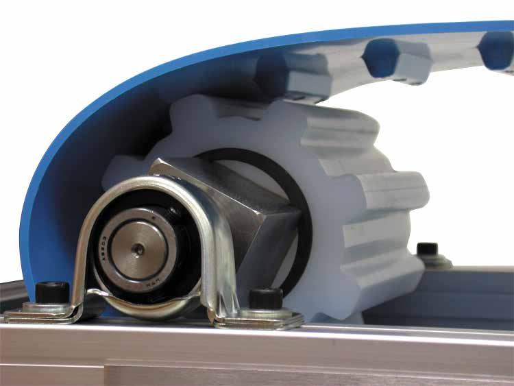
3 1. Introduction SuperDrive, the homogeneous positive drive belt, globally recognized as the best choice where hygiene control and conveying efficiency are essential. This distinctive design combines positive drive benefits with Volta s firm commitment to superior quality, increasing hygiene standards and productivity. Drive Pulley Drive Pulley Tail Pulley Tail Pulley SuperDrive TM components Material Features Fully extruded integrated teeth on the drive side function as a positive drive system and simultaneously serve as a built in guide mechanism reducing tensioning and offtracking.the homogeneous character makes sure that there are no crevices where bacteria may harbor making cleaning simple and increasing product life considerably. Volta s eco friendly belts allow drastic reduction in water usage and converts cleaning time to precious production time. Smooth homogenous nonporous surfaces prevent bacteria buildup resulting in maximum product shelflife. No plies, edge fraying or modular components or hinges that can break apart and find their way into your final product. Non absorbent of water, oils or chemicals. Smooth surface prevents product sticking, considerably reducing waste. Not absorbent of smells. Wide operating temperature range. FDA/USDA AMS Equipment Acceptance Certificate in compliance with NSF/ANSI/3A for Meat and Poultry Processing. USDA Dairy Equipment for selected products. Declaration of Conformity in compliance with EU Regulations No.: 10/2011, 1935/2004 and Directive 2002/72/EC. Supports the HACCP concept. Mechanical Benefits Teeth are an integral part of the belt, eliminating breakages at weak points and increasing the life of the belt. Extruded teeth and pulley system positively drive and track the belt, creating a smooth running production line. Minimal pretension reduces strain on the belt and prevents elongation. Reduces noise levels to a minimum. Easy to install and forms a strong base for quality heat welded HF welded fabrications. Lightweight conveyor belt, cutting back on motor energy usage. 3
4 SuperDrive Technical Manual 2. Technical Data Volta H Material SuperDrive Belts FHWSD and FHBSD are designed for long conveyors with particularly heavy loads and for use in harsh chemical conditions. The 4mm and the 6mm are suited to cutting and chopping on the belt Material: Volta HW, Beige / Volta HB, Blue Shore Hardness: 55D Temperature Range : 20 C to 75 C / 5 F to 170 F Coefficient of Friction: Steel: 0.4 / Stainless Steel: 0.4 / UHMW: 0.2 Certification: FDA/ USDA/ USDA Dairy/ EU Approved Table 2.1 Product Belt Thickness Belt weight (kg/ m 2 ) Add for each row of teeth Belt weight (lb/ ft 2 ) Add for each row of teeth FHB3 SD FHW3 SD kg/ m kg/ m 0.74 lb/ ft lb/ ft FHB3 SD ITE FHW3 SD ITE FHB3 SD FHW3 SD ITO kg/ m kg/ m 0.74 lb/ ft lb/ ft kg/ m kg/ m 0.71 lb/ ft lb/ ft FHB4 SD FHW4 SD 4.8 kg/ m kg/ m FHB4 SD ITE FHW4 SD ITE 4.8 kg/ m kg/ m SuperDrive ITE SuperDrive ITO 50 SuperDrive Smooth Surface FHB4 SD FHW4 SD ITO kg/ m kg/ m FHB6 SD lb/ ft lb/ ft 0.98 lb/ ft lb/ ft 0.92 lb/ ft lb/ ft 7.2 kg/ m kg/ m 1.48 lb/ ft lb/ ft Minimum pulley diameter Temp 0 C/32 F Temp < 0 C/32 F Temp 0 C/32 F Temp < 0 C/32 F Temp 0 C/32 F (normal flex) 126 mm / mm/ mm / mm/ mm/ Minimum pulley diameter Temp 0 C/32 F Temp < 0 C/32 F Temp 0 C/32 F Temp < 0 C/32 F (back flex) 189 mm / mm/ mm / mm/ 12.4 Temp 0 C/32 F 340 mm/ Max pull force (kg/ cm width) Max pull force (lb/ in. width) Note: *6mm material SuperDrive TM belts are usually used in heavy load applications and therefore we recommend using the largest Drive Pulleys possible to ensure maximum engagement between belt and Drive Pulley teeth. All inch sizes have been converted from metric sizes. 3,4 or 6mm Base Belt Thickness : 3,4 or 6mm Pitch Between Teeth : 39.7 ±0.4 Tooth Width : 13mm Tooth Height : 8mm 78 A 605 B Standard width (2 rows of teeth) : 1524mm / 60 Max belt width with one row of teeth : 910mm / 35.8 Min. belt width with two rows of teeth: 800mm / 31.5 Distance between teeth rows, center to center : 605 ±2mm / ±0.08 Tooth Length: 78mm / 3.07 B = A ± 5mm 1524 Belt Width W< <W<910 W>910 1 row 1 row or 2 rows 2 rows 4 Volta Belting Technology Ltd.
5 Pulley Guidelines & Fabrication Options Table 2.2 Belt Type FHW3 SD / FHB3 SD Temperature Temp 0 C/32 F Temp < 0 C/32 F Temp 0 C/32 F Note: NR Not Recommended. Contact your local distributor for further details regarding the 6mm thick SuperDrive belt. FHW4 SD / FHB4 SD Temp < 0 C/32 F MPD Base Belt 126mm / 4.96" 150mm / 5.9" 176mm / 6.93" 210mm /8.27" Minimum Pulley Diameter for VFlights Electrode VW / VWB 10 VW / VWB 13 VW / VWB mm / 6.22" 183mm / 7.20" 203mm / 7.99" 243mm / 9.56" 182mm / 7.16" 207mm / 8.15" 227mm / 8.93" 267mm / 10.5" 191mm / 7.52" 211mm / 8.30" 236mm / 9.29" 276mm / 10.86" 225mm / mm / mm / mm / 12.2 Single Electrode 7 Single Electrode 9 Double Electrode 7 Double Electrode 9 Minimum Pulley Diameter for Electrode Welded Flat Flights 183mm / 7.20" 207mm / mm / 8.50" 250mm / mm / 7.99" 227mm / mm / 9.29" 270mm / mm / 8.58" 242mm / mm / 9.88" 285mm / NR NR Pulleys: must be equal to, or larger than the minimum pulley specification. Flights: should be welded between the teeth as indicated in the sketch. Can be welded over the teeth if they do not exceed the tooth width. Must not be welded next to the teeth as indicated in the sketch. Recommended Flights Welding Location * Locations 1&4 are not recommended because the flight is in line with the tooth engagement area. * Locations 2&3 are recommended. Pulley teeth driving area Note: In location 2, it is essential that the cleat and weld widths do not exceed the width of the belt tooth. 5

6 SuperDrive Technical Manual Volta M Material SuperDrive Belts FMWSD and FMBSD are designed for conveyors where fabrications or sidewalls are needed. Material: Volta MW, Beige / Volta MB, Blue Shore Hardness: 53D Temperature Range : 20 C to 60 C / 5 F to 140 F Coefficient of Friction: Steel: 0.5 / Stainless Steel: 0.5 / UHMW: 0.28 Certification: FDA/ USDA/ USDA Dairy/ EU Approved SuperDrive ITE SuperDrive ITO 50 SuperDrive Smooth Surface Table 2.3 Product FMB3 SD FMW3 SD kg/ m kg/ m 0.74 lb/ ft lb/ ft FMB3 SD ITE FMW3 SD ITE FMB3 SD ITO 50 3 FMB4 SD FMW4 SD FMB6 SD Belt Thickness Belt weight (kg/ m 2 ) Add for each row of teeth Belt weight (lb/ ft 2 ) Add for each row of teeth Minimum pulley diameter (normal flex)* Minimum pulley diameter (back flex)* 3.6 kg/ m kg/ m 0.74 lb/ ft lb/ ft 3.5 kg/ m kg/ m 0.71 lb/ ft lb/ ft 4.8 kg/ m kg/ m 0.98 lb/ ft lb/ ft 7.2 kg/ m kg/ m 1.48 lb/ ft lb/ ft 80 mm/ 3 1 /4 120 mm/4 3 /4 240 mm/ mm/ mm/ mm/ 11 Max pull force (kg/ cm width) Max pull force (lb/ in. width) Note: *6mm material SuperDrive TM belts are usually used in heavy load applications and therefore we recommend using the largest Drive Pulleys possible to ensure maximum engagement between belt and Drive Pulley teeth. All inch sizes have been converted from metric sizes. 3, 4 or 6mm Base Belt Thickness : 3, 4 or 6mm Pitch Between Teeth : 39.7 ±0.4 Tooth Width : 13mm Tooth Height : 8mm 78 A 613 B Standard width (2 rows of teeth) : 1524mm / 60 Max belt width with one row of teeth : 910mm / 35.8 Min. belt width with two rows of teeth: 800mm / 31.5 Distance between teeth rows, center to center : 613 ±2mm / ±0.08 Tooth Length: 78mm / 3.07 B = A ± 5mm 1524 Belt Width W< <W<910 W>910 1 row 1 row or 2 rows 2 rows 6 Volta Belting Technology Ltd.
7 Pulley Guidelines & Fabrication Options Table 2.4 Belt Type FMW3 SD / FMB3 SD FMW4 SD / FMB4 SD MPD Base Belt 80mm 3¼ 120mm 4¾ Minimum Pulley Diameter for VFlights Electrode 120mm mm 5.90 VLC / VLB mm mm 6.70 VLC / VLB mm mm 7.08 VLC / VLB mm mm 7.68 Minimum Pulley Diameter for Electrode Welded Flat Flights Single Electrode 7 125mm mm 5.90 Single Electrode 9 140mm mm 6.50 Double Electrode 7 165mm mm 7.48 Double Electrode 9 NR NR Minimum Pulley Diameter for High Frequency Welded Flat Flights App. Temperature Temp 0 C / 32 F Temp < 0 C / 32 F Temp 0 C / 32 F Temp < 0 C / 32 F Flight 3 5 mm 101mm mm mm mm 7.09 Flight 6 8 mm 128mm mm mm mm 7.87 Minimum Pulley Diameter for Based Sidewalls Normal Flex SW20 105mm 4 1 / /4 SW30 105mm 4 1 / /4 SW40 115mm 4 1 / /8 SW50 125mm /8 SW60 130mm 5 1 / /8 SW80 150mm SW mm Minimum Pulley Diameter for Baseless Sidewalls Normal Flex Back Flex Normal Flex Back Flex BSW 30mm/ 1 80mm mm mm mm 5.90 BSW 40 mm/ mm mm mm mm 5.90 BSW 50 mm/ 2 1.6mm 100mm mm mm mm 6.30 BSW 60 mm/ 2.5 Thick 110mm mm mm mm 7.48 BSW 80 mm/ 3 130mm mm mm mm 9.45 BSW 100 mm/ 4 160mm mm mm mm 12.2 BSW 130 mm/ 5 2mm 210mm mm mm mm BSW 150 mm/ 6 Thick 250mm mm mm mm 18.5 Minimum Pulley Diameter for Two Top Guides: see page 24 Note: NR Not Recommended. Contact your local distributor for further details regarding the 6mm thick SuperDrive belt. All inch sizes have been converted from metric sizes. Electrode Welded Flights: We recommend welding the flights above the teeth location and flight thickness should not exceed the tooth base width. Sidewalls: must be positioned with a minimum gap of 100mm from the belt teeth. Flights: should be welded between the teeth as indicated in the sketch. Can be welded over the teeth if they do not exceed the tooth width. Must not be welded next to the teeth as indicated in the sketch. Pulleys: must be equal to, or larger than the minimum pulley specification. 7

8 SuperDrive Technical Manual Volta MD Metal Detectable Material SuperDrive Belts Material: Volta MB MD, Blue Shore Hardness: 53D Temperature Range : 20 C to 60 C / 5 F to 140 F Coefficient of Friction: Steel: 0.5 /Stainless Steel: 0.5 /UHMW: 0.28 Certification: FDA/ USDA/ USDA Dairy/ EU Approved SuperDrive Smooth Surface MD Table 2.5 Product FMB3 SD MD Belt Thickness 3 Belt weight (kg/ m 2 ) Add for each row of teeth Belt weight (lb/ ft 2 ) Add for each row of teeth 3.75 kg/ m kg/ m 0.77 lb/ ft lb/ ft Minimum pulley diameter (normal flex)* Minimum pulley diameter (back flex)* 100 mm/ mm/ 4.33 Max pull force (kg/ cm width) 6 Max pull force (lb/ in. width) Note: *All inch sizes have been converted from metric sizes. 3mm Base Belt Thickness : 3mm Pitch Between Teeth : 39.7 ±0.4 Tooth Width : 13mm 13 Tooth Height : 8mm A 613 B Standard width (2 rows of teeth) : 1524mm / 60 Max belt width with one row of teeth : 910mm / 35.8 Min. belt width with two rows of teeth: 800mm / Distance between teeth rows, center to center : 613 ±2mm / ± Tooth Length: 78mm / 3.07 B = A ± 5mm Belt Width W< <W<910 W>910 1 row 1 row or 2 rows 2 rows 8 Volta Belting Technology Ltd.
9 Pulley Guidelines & Fabrication Options Table 2.6 Belt Type FMW3 SD MD MPD Base Belt 100mm Minimum Pulley Diameter for VFlights 4 Electrode 135mm 5.31 VLB mm 5.70 VLB mm 6.10 VLB mm 6.70 Minimum Pulley Diameter for Electrode Welded Flat Flights Single Electrode 7 140mm mm 5.90 Single Electrode 9 150mm mm 6.50 Double Electrode 7 180mm mm 7.48 Double Electrode 9 NR NR Minimum Pulley Diameter for High Frequency Welded Flat Flights App. Temperature Temp 0 C Temp 32 F Temp < 0 C Temp < 32 F Flight 3 5 mm 116mm mm 6.50 Flight 6 8 mm 143mm mm 7.67 Minimum Pulley Diameter for Based SidewallsNormal Flex SW20 105mm 4 1 /8 SW30 SW40 SW50 SW60 105mm 115mm 125mm 130mm 4 1 /8 4 1 / /8 SW80 150mm 6 SW mm 8 Minimum Pulley Diameter for Baseless Sidewalls Normal Flex Back Flex BSW 30mm/ 1 110mm mm 4.72 BSW 40 mm/ mm mm 4.72 BSW 50 mm/ 2 1.6mm 110mm mm 5.90 BSW 60 mm/ 2.5 Thick 110mm mm 7.10 BSW 80 mm/ 3 130mm mm 9.05 BSW 100 mm/ 4 160mm mm BSW 130 mm/ 5 2mm 210mm mm BSW 150 mm/ 6 Thick 250mm mm Minimum Pulley Diameter for Two Top GuidesContact your local distributor Note: NR Not Recommended. All inch sizes have been converted from metric sizes. Disclaimer: Volta Belting Ltd. recommends testing all the products in your environment to ascertain suitability. The information is supplied in good faith without warranty. Guidelines and Suggested Materials for the Fabrication of FMB3 SD MD belt Electrode Welded Flights: We recommend welding the flights above the teeth location and flight thickness should not exceed the tooth base width. Sidewalls: must be positioned with a minimum gap of 100mm from the belt teeth. Flights: should be welded between the teeth as indicated in the sketch. Can be welded over the teeth if they do not exceed the tooth width. Must not be welded next to the teeth as indicated in the sketch. Pulleys: must be equal to, or larger than the minimum pulley specification. 9
10 SuperDrive Technical Manual Volta LT Low Temperature Material SuperDrive Belts Material: Volta MB LT, Blue Shore Hardness: 95A/ 46D Temperature Range : 35 C to 35 C / 31 F to 95 F Coefficient of Friction: Steel: 0.55 /Stainless Steel: 0.55 /UHMW: 0.30 Certification: FDA/ USDA/ USDA Dairy/ EU Approved SuperDrive Smooth Surface Table 2.7 Product FMB3 SD LT Belt Thickness 3 Belt weight (kg/ m 2 ) Add for each row of teeth Belt weight (lb/ ft 2 ) Add for each row of teeth 3.6 kg/ m kg/ m 0.74 lb/ ft lb/ ft Minimum pulley diameter (normal flex)* Minimum pulley diameter (back flex)* 80 mm/ 3 1 /4 100 mm/ 4 Max pull force (kg/ cm width) 3 Max pull force (lb/ in. width) 16.8 Note: *All inch sizes have been converted from metric sizes. 3mm Base Belt Thickness : 3mm Pitch Between Teeth : 39.7 ±0.4 Tooth Width : 13mm 13 Tooth Height : 8mm A 613 B Standard width (2 rows of teeth) : 1524mm / 60 Max belt width with one row of teeth : 910mm / 35.8 Min. belt width with two rows of teeth: 800mm / Distance between teeth rows, center to center : 613 ±2mm / ± Tooth Length: 78mm / 3.07 B = A ± 5mm Belt Width W< <W<910 W>910 1 row 1 row or 2 rows 2 rows 10 Volta Belting Technology Ltd.
11 Pulley Guidelines & Fabrication Options Table 2.8 Belt Type FMB3 SD LT MPD Base Belt 80mm Minimum Pulley Diameter for VFlights 3¼ Electrode 120mm 4.72 VLSB mm 5.12 VLSB mm 5.51 VLSB mm 6.10 Minimum Pulley Diameter for High Frequency Welded Flat Flights App. Temperature Temp 0 C Temp 32 F Temp < 0 C Temp < 32 F Flight 3 5 mm 101mm mm 5.94 Flight 6 8 mm 128mm mm 7.09 Minimum Pulley Diameter for Based Sidewalls (working temp. range 20 C to 40 C (4 F to 104 F)) SW20 105mm 4 1 /8 SW30 SW40 SW50 SW60 105mm 115mm 125mm 130mm 4 1 /8 4 1 / /8 SW80 150mm 6 SW mm 8 Minimum Pulley Diameter for Baseless Sidewalls Normal Flex Back Flex BSW 30mm/ 1 80mm mm 4.33 BSW 40 mm/ mm mm 4.72 BSW 50 mm/ 2 1.6mm 100mm mm 5.90 BSW 60 mm/ 2.5 Thick 110mm mm 7.10 BSW 80 mm/ 3 130mm mm 9.05 BSW 100 mm/ 4 160mm mm BSW 130 mm/ 5 2mm 210mm mm BSW 150 mm/ 6 Thick 250mm mm Minimum Pulley Diameter for Two Top Guides: see page 24 Note: All inch sizes have been converted from metric sizes. Guidelines and Suggested Materials for the Fabrication of FMB3 SD LT belt Sidewalls: It is possible to weld Sidewalls from L material to the LT belts. Sidewalls must be positioned at a minimum distance of 100mm from the belt teeth. Flights: We recommend using LT material as preferred Flights material. MB material is also acceptable but in this case you should make sure that the temperature of your application does not exceed the regular MB LT materials limit. The flights should be welded between the teeth as indicated in the sketch. Can be welded over the teeth if they do not exceed the tooth width. Must not be welded next to the teeth as indicated in the sketch. Electrodes: We do not recommend using electrodes for welding flights on these belts. The entire belt area around the welded electrode becomes rigid and the belt s flexibility is lost. HF Welding: We only approve HF welding of flights on LT belts. Endless Joining: We recommend joining LT belts with a Butt weld using the FBW Tool. 11

* 3 4 3.6 kg/ m 2 + 0.180 kg/ m 0.74 lb/ ft 2 + 0.121 lb/ ft 4.8 kg/ m 2 + 0.180 kg/ m 0.98 lb/ ft 2 + 0.")
12 SuperDrive Technical Manual Volta Z Material SuperDrive Belts for General Conveying Material: Volta Z, Dark Green Shore Hardness: 95A Temperature Range : 30 C to 60 C/ 20 F to 140 F Coefficient of Friction: 0.55/ Stainless Steel: 0.55/UHMW:0.3 SuperDrive Smooth Surface Table 2.9 Product FZ3 SD FZ4 SD Belt Thickness Belt weight (kg/ m 2 ) Add for each row of teeth Belt weight (lb/ ft 2 ) Add for each row of teeth Minimum pulley diameter (normal flex)* Minimum pulley diameter (back flex)* kg/ m kg/ m 0.74 lb/ ft lb/ ft 4.8 kg/ m kg/ m 0.98 lb/ ft lb/ ft 80 mm/ 3 1 /4 120 mm/ 4 3 /4 100 mm/ mm/ 6 Max pull force (kg/ cm width) Max pull force (lb/ in. width) Note: *4mm material SuperDrive TM belts are usually used in heavy load applications and therefore we recommend using 12 teeth or larger Drive Pulleys to ensure maximum engagement between belt and Drive Pulley teeth. *All inch sizes have been converted from metric sizes. 3 or 4mm Base Belt Thickness : 3 or 4mm Pitch Between Teeth : 39.7 ±0.4 Tooth Width : 13mm 13 Tooth Height : 8mm A 613 B Standard width (2 rows of teeth) : 1524mm / 60 Max belt width with one row of teeth : 910mm / 35.8 Min. belt width with two rows of teeth: 800mm / Distance between teeth rows, center to center : 613 ±2mm / ± Tooth Length: 78mm / 3.07 B = A ± 5mm Belt Width W< <W<910 W>910 1 row 1 row or 2 rows 2 rows 12 Volta Belting Technology Ltd.
13 Pulley Guidelines & Fabrication Options Table 3.0 Belt Type FZ3 SD FZ4 SD MPD Base Belt 80mm 3¼ 120mm 4¾ Minimum Pulley Diameter for VFlights Electrode 120mm mm 5.90 VLC / VLB mm mm 6.70 VLC / VLB mm mm 7.08 VLC / VLB mm mm 7.68 Minimum Pulley Diameter for Electrode Welded Flat Flights Single Electrode 7 125mm mm 5.90 Single Electrode 9 140mm mm 6.50 Double Electrode 7 165mm mm 7.48 Double Electrode 9 NR NR Minimum Pulley Diameter for High Frequency Welded Flat Flights App. Temperature Temp 0 C / 32 F Temp < 0 C / 32 F Temp 0 C / 32 F Temp < 0 C / 32 F Flight 3 5 mm 101mm mm mm mm 7.09 Flight 6 8 mm 128mm mm mm mm 7.87 Minimum Pulley Diameter for Based Sidewalls Normal Flex SW20 SW30 SW40 SW50 SW60 SW80 SW mm 105mm 115mm 125mm 130mm 150mm 200mm 4 1 /8 4 1 /8 4 1 / / /4 4 3 /4 5 1 /8 5 1 /8 5 3 /8 6 8 Minimum Pulley Diameter for Baseless Sidewalls Normal Flex Back Flex Normal Flex Back Flex BSW 30mm/ 1 80mm mm mm mm 5.90 BSW 40 mm/ mm mm mm mm 5.90 BSW 50 mm/ 2 1.6mm 100mm mm mm mm 6.30 BSW 60 mm/ 2.5 Thick 110mm mm mm mm 7.48 BSW 80 mm/ 3 130mm mm mm mm 9.45 BSW 100 mm/ 4 160mm mm mm mm 12.2 BSW 130 mm/ 5 2mm 210mm mm mm mm BSW 150 mm/ 6 Thick 250mm mm mm mm 18.5 Minimum Pulley Diameter for Two Top Side Guides: see page 24 Note: NR Not Recommended. Contact your local distributor for further details regarding the 6mm thick SuperDrive belt. All inch sizes have been converted from metric sizes. Electrode Welded Flights: We recommend welding the flights above the teeth location and flight thickness should not exceed the tooth base width. Sidewalls: must be positioned with a minimum gap of 100mm from the belt teeth. Flights: should be welded between the teeth as indicated in the sketch. Can be welded over the teeth if they do not exceed the tooth width. Must not be welded next to the teeth as indicated in the sketch. Pulleys: must be equal to, or larger than the minimum pulley specification. 13
14 SuperDrive Technical Manual Volta ZD Material SuperDrive Belts for General Conveying Material: Volta ZD, Black Shore Hardness: 95A Temperature Range : 30 C to 60 C/ 20 F to 140 F Coefficient of Friction: Steel: 0.55/ Stainless Steel: 0.55/UHMW:0.3 SuperDrive Smooth Surface Table 3.1 Product FZD6 SD Belt Thickness 6 Belt weight (kg/ m 2 ) Add for each row of teeth Belt weight (lb/ ft 2 ) Add for each row of teeth 7.2 kg/ m kg/ m 1.48 lb/ ft lb/ ft Minimum pulley diameter (normal flex)* Minimum pulley diameter (back flex)* 230 mm/ mm/ 10 Max pull force (kg/ cm width) 10 Max pull force (lb/ in. width) 56 Note: *6mm material SuperDrive TM belts are usually used in heavy load applications and therefore we recommend using the largest Drive Pulley possible to ensure maximum engagement between belt and Drive Pulley teeth. *All inch sizes have been converted from metric sizes. 6mm Base Belt Thickness : 6mm Pitch Between Teeth : 39.7 ±0.4 Tooth Width : 13mm 13 Tooth Height : 8mm A 613 B Standard width (2 rows of teeth) : 1524mm / 60 Max belt width with one row of teeth : 910mm / 35.8 Min. belt width with two rows of teeth: 800mm / Distance between teeth rows, center to center : 613 ±2mm / ± Tooth Length: 78mm / 3.07 B = A ± 5mm Belt Width W< <W<910 W>910 1 row 1 row or 2 rows 2 rows 14 Volta Belting Technology Ltd.

15 Volta MB/BL Material SuperDrive Belts for General Conveying Material: Volta MB,Blue Bottom, BL,Black Top Shore Hardness: Bottom= 53D, Top = 86A Temperature Range : 20 C to 60 C/ 5 F to 140 F Coefficient of Friction: Steel: 0.5/ Stainless Steel: 0.5/UHMW:0.28 SuperDrive Smooth Surface Table 3.2 Product FMB BL6 SD Belt Thickness 6 Belt weight (kg/ m 2 ) Add for each row of teeth Belt weight (lb/ ft 2 ) Add for each row of teeth 7.2 kg/ m kg/ m 1.48 lb/ ft lb/ ft Minimum pulley diameter (normal flex)* Minimum pulley diameter (back flex)* 200 mm/ 7 7 / mm/ 9 Max pull force (kg/ cm width) 8 Max pull force (lb/ in. width) 44.8 Note: *6mm material SuperDrive TM belts are usually used in heavy load applications and therefore we recommend using the largest Drive Pulley possible to ensure maximum engagement between belt and Drive Pulley teeth. *All inch sizes have been converted from metric sizes. 6mm Base Belt Thickness : 6mm Pitch Between Teeth : 39.7 ±0.4 Tooth Width : 13mm 13 Tooth Height : 8mm A 613 B Standard width (2 rows of teeth) : 1524mm / 60 Max belt width with one row of teeth : 910mm / 35.8 Min. belt width with two rows of teeth: 800mm / Distance between teeth rows, center to center : 613 ±2mm / ± Tooth Length: 78mm / 3.07 B = A ± 5mm Belt Width W< <W<910 W>910 1 row 1 row or 2 rows 2 rows 15
, 150 mm (6 ) and 200 mm (8 ) with a square bore.")
16 SuperDrive Technical Manual 3. Accessories Volta Belting provides all the accessories required to operate the SuperDrive belt. Drive Pulley SuperDrive TM pulleys are compatible with both H and M material belts.the standard pulley diameters are 100 mm (4 ), 150 mm (6 ) and 200 mm (8 ) with a square bore. Other dimensions are available on request. For more information consult your local Volta dealer. Volta Pulleys are manufactured from abrasion resistant materials that ensure a long and reliable operating life. All pulleys are made from FDA approved material. Drive Pulley Tail Pulley The tail pulley has smooth surfaces with a guide groove for the belt teeth. This pulley is available with the same dimensions and bore description as the drive pulley. Tail Pulley Support Pulley The support pulleys are designed to support the belt for heavy loads or when the belt is significantly wider than the drive and tail pulleys (see Selection of Support Pulleys on Page 33). The support pulley has a smooth surface and is available in a standard width of 100 mm/4. This pulley is available with the same diameter and bore description as the drive pulley. Support Pulley SuperDrive Drive Pulley Specifications SuperDrive 3mm & 4mm Thick Belts SuperDrive 6mm Thick Belts Number of Teeth O.D. Ø Pulley Pitch Ø O.D. Ø Pulley Pitch Ø Note: 4mm material SuperDrive belts are usually used in heavy load applications and therefore, we recommend using 12 teeth or larger Drive Pulleys to ensure more engagement between belt and Drive Pulley teeth. 6mm material SuperDrive belts are usually used in heavier load applications and therefore we recommend using the largest Drive Pulley available to ensure more engagement between the belt and Drive Pulley teeth. Standard Drive & Tail Pulley Width = mm / 7½ +3/8 Standard Support Pulley Width = mm / 3¾ +3/16 Standard Square Bore Dimensions = 40mm / 1½ NonStandard Round Bores are available upon request. NonStandard Square Bore Dimensions, available upon request: 25mm / 1 ; 50mm / 2 ; 2½. 16 Volta Belting Technology Ltd.


 is made of two plastic parts that locked with two bolts. The collar can be assembled without dismantling the shaft.")
17 Pulley Bore Description The SuperDrive drive, tail and support pulleys are available in two standard square bore dimensions 1 1 /2 and 40 mm. The 1 1 /2 square bore dimension is also available with round corners. The round corner bore is designed to provide a channel for water to carry debris away during washdown. Pulley bore dimensions should be chosen according to the load on the shaft to avoid shaft deflection and to transmit the required torque. Standard bore Pulley bore patterns Round Corner bore Securing SuperDrive Pulleys: Locking Collars Standard Locking Collar is made of two parts of stainless steel wire with locking bolts. This system can be assembled without dismantling the shaft and can be used with all sprocket types on 1½ ( 40mm) square shafts. Square Metal Locking Collar Square Plastic Locking Collar (UHMW) is made of two plastic parts that locked with two bolts. The collar can be assembled without dismantling the shaft. It can be used with pulleys that have 12 or more teeth and are available in 1½ in/ 40mm. It can be ordered with round corners. Locking Collar face width = 20mm Square Plastic (UHMW) Locking Collar Round Plastic Locking Collar (UHMW) is suitable for 8 teeth sprocket and larger. The shaft can be dismantled in order to assemble this locking collar. The collar can be ordered in 1½ in/40mm and also with round corners for 1½ in. shaft. Locking Collar face width = 20mm Additional Options for Securing SuperDrive Pulleys Round Plastic (UHMW) Locking Collar Volta offers three options for customers who prefer to use a different method of securing the pulleys to the shaft. We recommend checking with your engineering department regarding the effects this will have on your conveyor shafts. Volta does not supply materials for this procedure nor is responsible for damage or weakening of the shaft when using one of these options. 1. Use a C ring on the shaft on either end of the pulley. Machine a groove suitable for the thickness of the C ring you are using. This method of securing the pulleys is standard with modular belting. 2. Drill and thread a hole at either end of the pulley. Mount an Allen screw in each hole to secure the pulley. 3. Mount a small piece of flat metal on either end of the pulley. Drill and thread a hole in the shaft and mount an Allen screw to secure the metal pieces. 17


18 SuperDrive Technical Manual Motorized Pulley With motorized pulleys, the motor, gearbox and shaft are totally enclosed within a drum motor shell. Power from the motor is transmitted through the gearbox, which is coupled to a geared rim fixed to the drum end housing. It is especially useful on fish factory ships, meat and poultry processing lines and in the production of milk and dairy products. In these applications, the motor and gears are enclosed within the drum which makes it impervious to high pressure cleaning as well as resistant to liquids from the process itself. An added benefit when using SuperDrive is that it creates a complete conveying system that is hygienic and easily cleaned. Volta cooperates with several of the best known motorized pulley manufacturers to develop drum motors fitted with pulleys and teeth suitable to the SuperDrive conveyor belt. Please contact your local Volta belting distributor or Volta Belting for more information Drum motors can be fitted with UHMW shells (2) machined to close tolerances to fit over the stainless steel drum motor casing. The shell (2) is toothed to act as a drive sprocket and will have a series of (at least three) holes around its base on either side. Stainless steel rings (1) will fit over the motor casing (3) and corresponding pins fitted to these rings will engage the holes in the UHMW shell base (2). The rings (1) are secured to the motor casing by key way and grub screws (4). 3 2 The thickness of the steel rings (1) should not exceed that of the UHMW shell (2). As an alternative to plain rings, they can even be toothed to appear as a continuation of the shell this gives no inherent technical advantage. 1. Stainless steel ring + pins before engagement. 2. UHMW shell. 3. Motor Casing. 4. Threaded grub screw hole. 18 Volta Belting Technology Ltd.
 Return Rollers Snub Rollers when needed In particularly long conveyors")


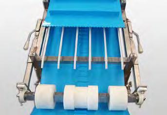
19 4. Conveyor Construction The classic conveyor construction consists of the following parts: Volta Drive Pulley Slidebed made of UHMW Strips Tail Pulley with Takeup Device (Tensioner) Additional support pulleys depending on the belt width and the projected load (see Belt Calculations on Page 35) Return Rollers Snub Rollers when needed In particularly long conveyors with heavy loads the use of roller slide bed as shown on Page 23 is recommended. Many conveyors have a special construction that allows a complete and quick removal of the belt without using lace. Suggested Conveyor Slidebed Construction with UHMW Strips 1.Recommended Dimensions for SuperDrive Belt with One Row of Teeth: B B B B A A. Distance between Guide Strips for the belt teeth: 85mm (3.35 ). B. Distance between Support Strips: mm (46 ). C. The distance of the front edge of the slide strip from the pulley depends on the cross section of the slide strip and the slide strip supports. Dimension C should be kept to a minimum but still leaving dimension X with a minimum of 20mm. C D. Distance between Drive Pulley Centre and Strip Surface: half of the drive pulley diameter. E. Distance between Slide Bed Surface and Return Bed Surface at180 contact engagement between the belt and pulley: pulley pitch diameter (= pulley diameter + belt thickness). F. Strip width : is 2550 mm (12 ). G. Maximum distance between the belt edges and strip : 50mm (2"). G B A F G B A G F 19
. B1. Distance between Support Strips: 100150mm (46 ). X1. Total distance of the Support Strips between the two Guide Strips. X1=520mm / 20.47 A1 X1 A1 B1 B1 B1 G1 A1 B1 F1 X1 F1.")
20 SuperDrive Technical Manual 2.Recommended Dimensions for SuperDrive Belt with Two Rows of Teeth Suitable for Both M and H Material Belts. A1. Distance between Guide Strips for the belt teeth: 89mm (3.5 ). B1. Distance between Support Strips: mm (46 ). X1. Total distance of the Support Strips between the two Guide Strips. X1=520mm / A1 X1 A1 B1 B1 B1 G1 A1 B1 F1 X1 F1. Strip width : is 2550 mm (12 ). G1. Maximum distance between the belt edges and strip : 50mm (2"). 20 Volta Belting Technology Ltd.
 (See Drawing 1). The belt can be allowed to sag between the return rollers.")

21 Return Rollers If the conveyor has a Takeup Device (Tensioner) and the belt has been tensioned between %, it will work with almost any arrangement of return rollers. Usually the maximum distance between the rollers A is 1.5 meters (5 ft) (See Drawing 1). The belt can be allowed to sag between the return rollers. However, it is important to avoid slack around the drive pulley in order to prevent the belt teeth from disengaging from the drive pulley during operation (See Drawing 2). The distance between the return rollers should allow the belt weight to prevent slack around the drive pulley. When positioning the return rollers one can allow a longer space in one location which can be used for the belt weight to create sagging at this location and ensure that sagging in the drive pulley area is prevented (See Drawing 3). A A B1 B2 A Drawing 1 Drawing 2 Drawing 3 Standard Belt Takeup Device (Tensioner) The SuperDrive belt requires hardly any pretension on most applications. The Takeup Device (Tensioner) has two functions on the conveyor. The first is to facilitate the mounting and splicing of the belt. Secondly, the quick release takeup Device (Tensioner) makes cleaning of belt easier. Opening the quick release Takeup Device (Tensioner) provides slack between the belt and pulleys, making cleaning more efficient. Belt tensioning length and structure depends on a number of factors: conveyor length, cleaning method and conveyor structure. As a minimum precaution, Volta recommends using a takeup of at least 58 inches ( mm). Quick Release Takeup Device (Tensioner) The Quick Release Takeup Device (Tensioner) maintains a consistent tensioning of the belt when returning the tensioner to its original position after releasing the belt for cleaning. The picture shows The takeup (Tensioner) in the open position. The belt may be lifted to provide easy and effective access to the underside of the belt, guides and pulleys for cleaning. After cleaning has been completed, close the quick release Takeup Device (Tensioner) in order to return the belt to its correct pretension and alignment without additional adjustments. Snub Rollers Snub Rollers are widely used to increase the arc of contact on the drive pulley and increase belt tension, thereby eliminating slack which can cause the belt to jump. The belt may sag, and return rollers can be positioned at equal distances to carry the sag. Safety precautions must be taken to prevent access to the snub roller working area. 21
. Several options for retrofit are available: 1.")


22 SuperDrive Technical Manual Conveyor Retrofit Retrofit of Conveyor with a Flat Slidebed These conveyors typically have outside walls. In this case strips are not necessary to guide the belt teeth (remember that the belt should not press against either one of the conveyor walls). Several options for retrofit are available: 1. Flat Slidebed The teeth can ride on the flat slidebed without affecting the belt operation. In this case, because of the SuperDrive TM teeth, the center line of the belt will be slightly higher than the edges of the belt. This construction is not recommended with M / LT / Z material belts. 2. Slidebed with a groove to accommodate SuperDrive teeth When a groove is added to the slidebed the belt operation becomes smoother and more efficient. In this case the belt will be guided by its teeth in the center groove and it should not touch the conveyor bed sidewalls. This construction is not recommended with M / LT / Z material belts in applications with heavy loads and long conveyors. 3. Slidebed with UHMW strips Slidebed as seen in accompanying drawing is the most recommended type, especially for SuperDrive M / LT / Z material belt applications. The UHMW strips reduce the coefficient of friction between the belt and the slidebed. This increases the carrying capacity of the belt. In this case, it may be necessary to raise the position of the drive and tail pulleys. Retrofit of Conveyor with a Roller Slidebed This type of conveyor is not typical of food applications. If you wish to install a SuperDrive belt on a roller bed conveyor, use rollers with grooves in order to guide the teeth and allow a smooth belt operation. Stainless Steel slidebed is least recommended especially when using SuperDrive M / LT / Z belts. 22 Volta Belting Technology Ltd.
23 Z or Swanneck Conveyor Construction The Z or swanneck conveyor is commonly used for lifting products. The SuperDrive TM is ideally suited for this application for several reasons: The SuperDrive TM material is relatively stiff across the belt and will not bend in the middle when the belt changes from a horizontal to an angled position. The SuperDrive TM operates without tension, therefore, eliminates problems of holding the belt in place. The transition areas (horizontal to elevation and back) can be assisted as for regular belts, by using a single large roller or a set of small rollers (see drawing below). UHMW Strip Bed Construction Roller Bed Construction Figure 1 Figure 2 1. Tail Pulley 2. Roller Set: Transition Horizontal to Incline 3. Incline UHMW Slide Bed 4. Top Roller: Transition Incline to Horizontal 5. Drive Pulley 6. Roller Set: Return transition horizontal to decline 7. Return Support Roller 8. Bottom Roller: Return transition decline to horizontal 9. Takeup Device (Tensioner) for tail pulley 1. Tail Pulley 2. Roller Set: Transition Horizontal to Incline 3. Roller Slide Bed 4. Top Roller: Transition Incline to Horizontal 5. Drive Pulley 6. Roller Set: Return transition horizontal to decline 7. Return Support Roller 8. Bottom Roller: Return transition decline to horizontal 9. Takeup Device (Tensioner) for tail pulley Figure 1 & 2 demonstrate typical Zelevator conveyor constructions with Fig.1 showing a slide bed made from UHMW and Fig 2 showing a roller slide bed. In applications with heavy loads & long conveyors it is important to use the roller slide bed type (Fig. 2) especially when using M / LT / Z type belts. In transition areas (2 & 4) the belt will tend to rub against the conveyors curved construction and to create an area of high tension strain and friction. Therefore, it is very important to use rollers at these two transition points to minimize the strain and friction. 23

24 SuperDrive Technical Manual There are 3 Typical Options for the Transition Areas The belt curve should be the maximum possible size and not less than the minimum pulley diameter of the specific belt with its fabrications. The bigger the curve, the less wear and tear. It is easiest to apply the roller set to larger curves. Do not use a shoe system with M material belts, heavy loads or long conveyors. This is the least preferred system. Shoe Roller Roller Set Swanneck conveyor transition rollers/ shoe (direction change) options For belts 600mm or wider we recommend using guides on both upper edge sides of the belt. The belt guides go through the vpulleys in the transition section to hold the belt (see the picture). This is the recommended method When using wide belts, it is very important to support the belt on the return side. Using cleats may cause problems and it may be necessary to make a center gap in the cleat to enable supporting the belt. Minimum Pulley Specifications for SuperDrive M / LT / Z Material Belts with Two Top Guides Guide Type SuperDrive 3mm Thick Belts SuperDrive 4mm Thick Belts Normal Flex Back Flex* Normal Flex Back Flex* VLB/VLC13 145mm / mm / mm / mm / 7.87 VLB/VLC mm / 7 175mm / mm / mm / 8.85 CLB/CLC13 124mm / mm / mm / mm / 7.48 CLB/CLC17 146mm / mm / mm / mm / 8.26 VSB/VSC mm / mm / mm / mm / 7.28 VSB/VSC17 145mm / mm / mm / mm / 7.87 CSB/CSC mm / mm / mm / mm / 7 CSB/CSC17 124mm / mm / mm / mm / 7.48 Note: * Back flex location can be seen in positions 2 and 6 on Figure 1 & 2 shown on page 23. Note: Contact your local distributor for further details regarding the 6mm thick SuperDrive belt. 24 Volta Belting Technology Ltd.


25 Trough Conveyors The SuperDrive TM belt can be used in trough conveyors. The belt teeth are usually positioned at the center of the belt. When designing the trough conveyor allow enough space for the belt teeth to lay flat. Trough Bed Construction Support strips Trough stainless steel bed Carrying rollers Carrying rollers Roller bed construction UHMW Strip Bed Transition Length There must be a minimum distance between the drive/ tail pulleys and the beginning of the trough since high tension is created on the belt sides and edges. This distance is called the transition length and is measured from the pulley centers at both ends of the conveyor. L Transition length (L) w α L = C * W L Transition length = C Factor from table* W Belt width Trough Angle ( ) C Factor The Pulley Construction and Height Location Due to the strain on the belt sides and edges, it is very important to use support pulleys to hold at least 80% of the belt underside, particularly at the edges. The drive and tail pulleys should be placed at the full trough depth or mm/ ¾ 1½ lower than the trough base depending on the conveyor construction and the belt width. This will enable the belt to take the trough shape when the load is low or the belt is relatively narrow or short. H α Pulley lower than the trough depth Pulley at the full trough depth Full trough depth 25
 300 mm/12 400 mm/16 500 mm/20 600 mm/24 10 No Yes Yes Yes 20 No Yes Yes Yes 30 No Yes Yes Yes 45 No * * * Note: Discuss")
26 SuperDrive Technical Manual Belt Tension The belt used on a trough conveyor must be pre tensioned to % so that the belt takes the trough shape. Allowed Belt Trough Angle FHW 3 SD and FHB3 SD Belt Width Trough Angle ( ) 300 mm/ mm/ mm/ mm/24 10 No Yes Yes Yes 20 No Yes Yes Yes 30 No Yes Yes Yes 45 No * * * Note: Discuss trough angle with your local distributor when choosing thicker SuperDrive belt. Allowed Belt Trough Angle FMW 3 SD and FMB3 SD Belt Width Trough Angle ( ) 300 mm/ mm/ mm/ mm/24 10 * Yes Yes Yes 20 * Yes Yes Yes 30 * Yes Yes Yes 45 * * Yes Yes Note: * When loaded, the belt will take the trough shape. Note: 6mm thick SuperDrive belt cannot be used for Trough conveyors. One method for ensuring a stiff belt takes up the trough form is to restrict it by means of a series of short shoes positioned along the conveyor length. Each shoe contains and restricts the outer part of the belt from above and below to prevent buckling or deforming while pressing the belt edge at the same time into the troughing. The shoes should be made from UHMW and the lower part under the belt should be longer than the upper part. Construction of Trough Conveyor when Using SuperDrive TM Belt with Two Rows of Teeth Trough stainless steel bed for belt with two rows of teeth. UHMW bed for belt with two rows of teeth. The same principle as for a belt with one row of teeth should be taken into consideration when strips are used to support a belt with two rows of teeth. It is important to leave a gap between the belt teeth and the nearest strip to the center side (B) to enable the belt to take the trough shape. The belt can be guided by the strips on the teeth closest to the outer side (A). When adding UHMW strips on an existing frame (see figure above), the strips should be at least 10 mm (3/8 ) high. 26 Volta Belting Technology Ltd.

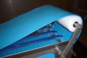
27 Center Drive Conveyor Tail Pulley Type Backbend Pulley Tail Pulley Type Drive Pulley Snub Rollers This conveyor is used in two typical applications: One option is when the drive sprocket is large, the tail sprocket can be much smaller within the limitations of the minimum sprocket diameter of the base belt making the conveyor most suitable for tight transition of products. Only the drive shaft should be fitted with sprocket and all other shafts should have smooth rollers. Another option is when the conveyor works in two directions. In this case you would need two snub rollers to ensure smooth operation. To prevent slippage and jumping the belt must be tensioned up to 0.5%. In most cases, snub rollers are placed both before and after the drive pulley, positioned tightly against the drive pulleys on both sides. This ensures smooth operation when the belt is running in both directions. Removing the Belt for Cleaning There are a number of options in the conveyor construction that allow the belt to be removed from the conveyor without being opened. Quick Release Takeup Device (Tensioner) This device permits the release of belt tension without losing belt alignment (Page 21).In some conveyors telescopic supports are used. During normal operation of the conveyor, the supports are flush with the sides of the conveyor. During cleaning or maintenance, the supports are pulled out and are in a position to hold the conveyor belt during cleaning and maintenance (see drawing). The Hinge Lace or Metal Lace can be used to open the belt for cleaning and maintenance (Page 2930). Conveyor Construction for quick dismounting of the belt and telescoping supports to hold the belt 27


28 SuperDrive Technical Manual 5. Splicing the SuperDrive The SuperDrive conveyor belt is extruded with a series of teeth as an integral part of the belt. These teeth are designed to mesh with the teeth on the SuperDrive drive pulley. To ensure efficient performance, it is necessary to maintain the spacing between the teeth in the region of the weld. We recommend using Volta Tools for this procedure. These tools are designed for use with all our belts and materials. They are also designed to maintain the correct spacing between the teeth on the SuperDrive belt. FT Electrode Welding Kit For the FT Welding System extruded electrodes are used for endless splicing Volta flat belts and Super Drive, DualDrive and DualDrive SP. The FT Welding System uses a router to cut the angle on the belt edges and to trim the weld on completion. The weld is carried out by using a Leister Hot Air Gun and Volta electrodes. When joining up to 2mm thick belts, use the 7mm section electrode and for a belt thicker than 2mm, the 9mm section electrode is used. This tool is supplied with a builtin adaptor for welding SuperDrive belts. The FT tool range offers maximum splicing width of 1000mm and 1500mm. FT electrode Welding kit FBW Flat Butt Welding Tool The FBW System was created to buttweld flat belts making them endless. The FBW Welding System can be used for SuperDrive, DualDrive, DualDrive SP and special textured top flat belts. The FBW tool range offers maximum splicing width up to 2300mm. FBW Welding Kit 28 Volta Belting Technology Ltd.


29 Metal Lace There are occasions when it may be necessary to splice the SuperDrive TM belt using lace. When working with lace, it is important that you work according to the recommendations of the lace manufacturer. When using lace for splicing the SuperDrive TM belt, the Pull Force calculations provided by Volta are not applicable. The distance between the teeth at the splice must be the same as the distance between the teeth on the rest of the belt. Metal laces are mounted on these surfaces Cut and scrapped Note: The spacing at the splice can be reduced by up to 23 mm without adversely affecting belt operation. However, the distance between the teeth should never be increased. Scrap Cut Scrap Figure 5a: Tooth pattern after joining the SuperDrive belt with lace Figure 5b: Shows the correct spacing between teeth with one missing tooth With some lacing products, such as the Alligator brand model RS62 and RS125, it may be necessary to remove one tooth completely. For these products, it will be necessary to cut each end of the belt at the base of a tooth (figure 5a). After mounting the Alligator brand metal lace, the belt will have a gap of one tooth (figure 5b). The loss of one tooth will not affect the operation of the belt. We do not recommend using this method when using pulleys of 12 teeth or less. 29


30 SuperDrive Technical Manual Plastic Hinge Lace The Plastic Hinge Lace allows you to easily open the belt by taking the hinge pin out, clean or service the conveyor, reinstall the belt and close the lace with a new pin. The Plastic Hinge Lace is made of Volta homogeneous food approved materials and is compatible with Volta M family product belts. Volta belts are renowned for their homogeneous and hygienic characteristics and, therefore, they do not require opening and joining on a regular basis unlike modular belts. Hinge Lace Benefits Easy OpenClose Technique Closing belt with Universal Lace The fastening structure allows you to easily open the Plastic Hinge Lace by removing the hinge pin from the lace. After setting up the belt on the conveyor, fasten the lace and secure it by inserting a new hinge pin into the slit and crimp up the pin ends L Reduced Maintenance Downtime Since Volta belts are extremely hygienic, you don t have to regularly install and uninstall your belt for cleaning. In cases where belt dismantling is necessary, Universal Lace provides you with the best solution. This is because the Volta Universal Lace will not tear off from the belt, since it is welded onto your belt and is made of the same homogeneous material. DETAIL B We recommend using the Universal Lace only when absolutely necessary. Make sure that the conveyor pulleys fully support the entire face length of the belt or at least 80% of the face length. Note that the maximum allowed pull force for the lace (per cm/ in.) is lower than the allowed pull force of the belt (per cm/ in.). Therefore, check that the calculated pull force of your belt is lower than the maximum allowed pull force of the lace. B A DETAIL A Plastic Hinge Lace Specifications Description Material Hardness Volta LMWU Flat toothed strip Volta MW, beige 95A Volta LMBU Flat toothed strip Volta MB, blue Working Temp Range 20 C to 60 C/ 5 F to 140 F 20 C to 60 C/ 5 F to 140 F Dimensions Max Length Max Pull Force 5 x 16 mm 0.2 in x 0.63 in 3.05 m 10 ft 3 kg/cm 16.8 lb/in 95A 5 x 16 mm 0.2 in x 0.63 in 3.05 m 10 ft 3 kg/cm 16.8 lb/in Minimum Pulley Normal Flex with SD 3mm Minimum Pulley Back Flex with SD 3mm Hinge Pin 80 mm/ 3 1 / 8 in. 80 mm/ 31/ 8 in. 100 mm/ 4 in. Nylo Steel: 1.65mm/ 0.065, FDA approved 100 mm/ 4 in. 30 Volta Belting Technology Ltd.
31 6. Belt Calculations Pull Force Calculation Procedure 1. Net Pull Force F on the Belt is Calculated by the Formula F = f S * ( G 1+G 2 * X X H R * G 2 * + f R * G 3 + C * G 1 * * G 4 L L L Conveyor with slide bed L Return Bed Rollers with Bearings Rollers with Bushing UHMW Sliders f R = 0.03 f R = 0.1 f R = refer to technical data sheet Slide Bed fs = refer to technical data sheet, pgs. 4, 6 and 8 1. Horizontal transport C = 0; L = X; H = 0 L 2. Incline C = 1 L H X 3. Decline C = 1 L H X Symbols and Dimensions f R = Coefficient of friction of rollers (Bearings or Bushing) f S = Coefficient of friction of belt on slidebed L = Conveyor length (m)/ (ft) H = Elevating height (m)/ (ft) X = Horizontal distance of conveyor (m)/ (ft) G 1 = Maximum load on the conveyor (kg)/ (Lb) G 2 = Belt weight (one direction) (kg)/ (Lb) G 3 = Weight of supporting rollsupper and lower sections (kg)/(lb) G 4 = Maximum accumulated weight (kg)/ (Lb) * In case of Z Conveyor, the calculation is made up of two conveyors, one horizontal and one inclined. In order to find the total Pull Force, add the results of both calculations. 31
32 SuperDrive Technical Manual 2. Pull Force Per Unit Belt Width Divide the Calculated Pull Force from Step 1 by the belt width (cm or inch.) and record the answer. 3. Determine Allowed Pull Force and Pulley Diameter Pulley diameter affects the maximum allowable pull force (Fa). To determine the Allowable Pull Force (Fa), find the number of meshed teeth in the left hand column of Table 6a. If the number of meshed teeth is less than 6, multiply the Maximum Pull Force (Table 2.1, Page 4 for M belts or Table 2.3, Page 6 for H belts or Table 2.5 page 8 for LT belts or Table 2.7 page 10 for Z belts or Table 2.9 page 12 for ZD belts or Table 3.0 page 13 for MB/BL belts) by K Factor below. Table 6a: K Factor Teeth in Mesh KFactor Comments 6 or more arc of contact at standard 150 mm/6 pulley arc of contact at standard 100 mm/4 pulley Fa = Fmax * K Fa = Allowed pull force Fmax = Maximum pull force allowed for the belt (Technical Data table of each belt) K= Factor from Table 6a 4. Verify that the Selected Belt can Carry the Calculated Pull Force Compare the answer in step 2 to the Maximum Allowable Pull Force. If the Calculated Pull Force in Step 2, is less than or equal to Maximum Allowable Pull Force (Fa), then the selected belt is suitable for the application. You should continue with Step 5 to select the correct combination of Drive/Tail and Support Pulleys. If the Calculated Pull Force in Step 2 is greater than maximum Allowable Pull Force in Step 3, you must change one of the following parameters: Increase the belt width. Change the slidebed to reduce the coefficient of friction. Volta recommends using UHMW strips. Add a snub roller to increase the arc of contact (to increase the number of meshed teeth). Choose a larger diameter Pulley (to increase the number of meshed teeth). Reduce the load on the belt. 32 Volta Belting Technology Ltd.
33 5. Determine the Number of Support Pulleys Required For belts with one row of teeth add support pulleys in pairs. Tables 6b and 6c give the different pulley combinations based on the Pull Force. Locate the Calculated Pull Force from Step 1 in Tables 6b and 6c. The row heading indicates the pulley combination you will need for the conveyor drive and tail shafts. Volta recommends using support pulleys for any belt 600mm/24 : or wider regardless of the load weight. Table 6b: Selection of Support Pulleys for Belts with One Row of Teeth Belt type SDH3mm SDH4mm SDH6mm SDM3mm SDM4mm SDM6mm SDMB/BL6mm SDLT3mm SDZ3mm SDZ4mm SDZ6mm SDZD6mm Drive pulley only Drive with 2 support pulleys Drive with 4 support pulleys Drive with 6 support pulleys 20 cm / 8" width 203 kg / 448 lb 261 kg / 574 lb 406 kg / 893 lb 40 cm / 16" width 343 kg / 756 lb 441 kg / 970 lb 686 kg / 1509 lb 60 cm / 24" width 483 kg / 1065 lb 621 kg / 1366 lb 956 kg / 2103 lb 80 cm / 32" width 623 kg / 1374 lb 801 kg / 1762 lb 1246 kg / 2741 lb 138 kg / 304 lb 263 kg / 578 lb 388 kg / 854 lb 513 kg / 1130 lb 176 kg / 387 lb 336 kg / 739 lb 496 kg / 1091 lb 656 kg / 1443 lb 275 kg / 605 lb 176 kg / 387 lb 525 kg / 1155 lb 336 kg / 739 lb 775 kg / 1705 lb 496 kg / 1091 lb 1025 kg / 2255 lb 656 kg / 1443 lb 66 kg / 145 lb 110 kg / 242 lb 145 kg / 319 lb 220 kg / 484 lb 220 kg / 484 lb 126 kg / 277 lb 210 kg / 462 lb 277 kg / 609 lb 420 kg / 924 lb 420 kg / 924 lb 186 kg / 409 lb 310 kg / 682 lb 409 kg / 8998 lb 620 kg / 1364 lb 620 kg / 1364 lb Table 6c: Selection of Support Pulleys for Belts with Two Rows of Teeth Belt type SDH3mm SDH4mm SDH6mm SDM3mm SDM4mm SDM6mm SDMB/BL6mm SDLT3mm SDZ3mm SDZ4mm SDZ6mm SDZD6mm For belts with two rows of teeth, determine the number of Support Pulleys as follows 246 kg / 541 lb 410 kg / 902 lb 541 kg / lb 820 kg / 1804 lb 820 kg / 1804 lb Pull force (PF) for 2 Drive pulleys Pull Force (PF) for each additional Support pulley 406 kg / 896 lb 70 kg / 154 lb 522 kg / 1148 lb 90 kg / 198 lb 812 kg / 1786 lb 140 kg / 308 lb 276 kg / 608 lb 352 kg / 774 lb 550 kg / 1210 lb 352 kg / 774 lb 132 kg / 290 lb 220 kg / 484 lb 290 kg / 638 lb 62 kg / 136 lb 80 kg / 176 lb 125 kg / 275 lb 80 kg / 176 lb 30 kg / 66 lb 50 kg / 110 lb 66 kg / 145 lb 440 kg / 968 lb 100 kg /220 lb 440 kg / 968 lb 100 kg /220 lb 5.1. If the Calculated Pull Force from Step 1 is less than the values shown in Table 6b or Table 6c for the Pull Force of a Standard Pulley (one for each row of teeth), you will need two Drive Pulleys without Support Pulleys. Nevertheless, Volta recommends using one Support Pulley mounted between the two Drive Pulleys. For a belt wider than 1200mm we recommend using at least 3 support pulleys regardless of load (one support between two rows of teeth and one on either end side of the teeth) If the Calculated Pull Force in Step 1 is greater than the value shown in Table 6b or Table 6c Subtract the value in Table 6b or 6c from the calculated Pull Force (For example, for M material we subtract 276 kg / 608 lbs) Divide the answer by 62 kg/136 lbs (for M material, Table 6b) and round up the given value. This gives the number of Support Pulleys needed to meet the Pull Force requirements. For example, if the Pull Force is 320 kg/ 704 lbs. for a SD M belt with two rows of teeth, then the number of support pulleys that you need is calculated as follows: Metric Calculation English Calculation ( ) /62 = 0.7 and round up to 1 ( ) /136 = 0.7 and round up to 1 You will need one support pulley for each one of your conveyor drive and tail shafts. After selecting the number of Support Pulleys required, add the lengths of all the Pulleys (Drive and Support or Tail and Support) together and make sure that the total length of the pulleys is not larger than the width of the belt. 33


34 SuperDrive Technical Manual Installation and Positioning of Support Pulleys Volta recommends using support pulleys for any belt 600 mm/ 24 or wider regardless of the load. For belts with two rows of teeth, we recommend including at least one support pulley between the two drive pulleys. For a belt wider than 1200mm we recommend using at least 3 support pulleys regardless of the load (one support between two rows of teeth and one on either end side of the teeth). Support pulleys should be added according to the load to be carried on the belt and the belt width. The support pulleys should be positioned to remove any depressions in the belt surface. The figures bellow show how to arrange the support pulleys in the correct position. 6.2a 6.2b 6.2c 6.2d Figure 6.2a shows a depression between the two drive pulleys. In this situation, install at least one support pulley between the two drive pulleys as shown in Figure 6.2b. Figure 6.2c shows the belt with a support pulley between the drive pulleys but with the ends of the belt left unsupported. Figure 6.2d shows the installation of support pulleys under each belt edge. The support pulleys should be positioned symmetrically. 34 Volta Belting Technology Ltd.
35 Calculation Example A Stainless Steel slidebed conveyor that elevates meat packages. Check if the 450 mm (18 ) FMB3SD belt is suitable for the application and choose the pulley set (drive, tail and support pulleys) and the pulley diameter. Package Weight Conveyor Conditions 13.6 kg 30 lbs Maximum number of packages on the belt Conveyor Length (L) Conveying Height (H) 15.2 m 3 m 50 ft ft. Conveyor Horizontal Distance (X) 14.9 m 48.8 ft. Weight of Return Rollers 4.5 kg 10 lbs Number of Return Rollers 6 6 Pulley Diameter 152 mm Number of Teeth in Mesh 6 6 Accumulated Weight Calculate the Maximum Pull Force Metric X=14.9 H=3 L=15.2 fs = 0.5 (stainless steel slidebed) fr = 0.1 G1= 20*13.6=272 kg F=fs*(G1+G2)*X/L+fr*G2*X/L+fr*G3+C*G1*H/L+0.25*G4 English X=48.8 H=9.84 L=50 fs = 0.4 (stainless steel slidebed) fr = 0.1 G1= 20*30=600 lbs G2= (3.6*0.45*15.2)+(0.180*15.2)=27.4 kg G2=0.74*(18/12)*50+(0.121*50)=61.5 lbs G3= 6*4.5=27 kg G4= 0 F=0.5*( )*14.9/ *27.4*14.9/ *27+1 *272*3/ *0 F=205.8 kg G3= 6*10=60 lbs G4= 0 F=0.5*( )*48.8/50+0.1*61.5*48.8/50+0.1*60+1*600 *9.84/ *0 F=452.7 lbs 2. Calculate the Pull Force Per Unit Width of Belt 205.8/45 = 4.6 kg/cm or 452.7/18 = lbs/inch. 3. Determine Allowable Pull Force and Pulley Diameter Fa=Fmax * K Fmax = 6.25 kg/cm (35 lb/in.) see Maximum Pull Force in Technical Data on Page 6 K = 1 (180 arc of contact at standard 150 mm/6 in. pulley) 35
36 SuperDrive Technical Manual 4. Verify that the Selected Belts can Carry the Calculated Pull Force The Pull Force per unit width of belt, 4.6 kg/cm (32.5 lbs/ft) is less than the allowable Pull Force for 6 or more teeth in mesh. Therefore you can use 150 mm (6 ) pulleys with 180 o arc of contact. If you require a 100 mm (4 ) pulley for design reasons, calculate as follows: Fa=6.25*0.6=3.75 kg/cm or Fa=35*0.6=21 lb/in. (k = 0.6 for 4 teeth in mesh) The allowable Pull Force 4.2 kg/cm (23.5 lb/inch.) is less than the application requirements 5.7 kg/cm (32.5 lb/inch). You must change one of the parameters listed in Step 4, Page 25. For example, if you change the slidebed to UHMW strips, the coefficient of friction will be 0.28 and therefore, the Calculated Pull Force from Step 1 will be kg (312 lbs). The Pull Force per unit width of belt will be: 141.8/45 = 3.15 kg/cm or 312/18 = lbs/inch. This change brings the Pull Force per unit width below 3.75 kg/cm (21 lbs/ft). So you can use a 100 mm (4 ) pulley. 5. Determine Support Pulley Requirements The calculated pull force is kg (452.7 lbs) and the Pull Force for a Standard Pulley without supports is 138 kg (304 lbs.) as shown in Table 6b, Page 31. Therefore we must use the standard Drive Pulley with 2 Support Pulleys. This arrangement can take up to 263 kg (578 lbs.) of Pull Force. The length of the drive pulley and two support pulleys is shorter than the belt * 100 = 400mm * 4 = 16 inch. And the belt is: 450 mm 18 inch. 36 Volta Belting Technology Ltd.
37 7. Motor Capacity Calculation Calculation Procedure (for Constant Speed) Metric 1. Calculation of the required torque for the drive pulley M = torque [N * m] M = F* 9.81*Dp 1000 * 2 M = torque [lb. * ft.] English F* Dp M = 12 * 2 F = calculated pull force [kg] see section 1, pg. 29 F = calculated pull force [lb.] see section 1, pg. 29 Dp = pulley pitch diameter [mm] see page 14 Dp = pulley pitch diameter [in.] see page Calculation of drive pulley revolution [rpm] V*1000 n = π*dp n = number of drive pulley revolution [rpm] Dp = pulley pitch diameter [mm] see page 14 V = belt speed [m/min] n = V*12 π*dp n = number of drive pulley revolution [rpm] Dp = pulley pitch diameter [in.] see page14 V = belt speed [ft./min] 3. Calculation of the motor capacity M*n P = 9550*η *k M*n P = 5250*η *k P = power in [Kw] (0.746 Kw = 1 HP) P = power in [HP] (1 HP = Kw) M = torque [N. m] (from step 1) M = torque [lb.. ft.] (from step 1) n = number of drive pulley revolution [rpm] (from step 2) n = number of drive pulley revolution [rpm] (from step 2) η = efficiency of the drive transmission equipment (η < 1) η = efficiency of the drive transmission equipment (η < 1) It depends on the drive type and motor data provided by the manufacturer. In most cases it may vary from 0.6 to k = correction/ safety coefficient (K > 1) k = correction/ safety coefficient (K > 1) Take into account working conditions according to the motor and drive gear data provided by the manufacturer. 4. Choose a motor: the next size up 37
38 SuperDrive Technical Manual Notes 38 Volta Belting Technology Ltd.
39 39


40 Think Positive! Think SuperDrive TM! SD Tail Pulley SD Drive Pulley SD Drive & Support Pulley SuperDrive Working Under Water Perforated SD Belt With Cleats On Site Welding SD LT Low Temperature "Z" or Swanneck Conveyor Trough Conveyor Corporate Headquarters Sales and Manufacturing USA Tel: Fax: Toll Free: 1877VOLTAUS EUROPE Tel: Fax: Volta Belting makes no warranty with respect to any of its products for a particular purpose. See Volta General Terms and Conditions. Copyright 2015 Volta Belting Technology Ltd. CAT200EN00 Ver. I May 2015
SuperDrive. Think Positive! Think SuperDrive TM! Technical Manual. The Next Step in Belting. SD Drive & Support Pulley. Perforated SD Belt With Cleats
 Think Positive! Think SuperDrive TM! SuperDrive Technical Manual SD Tail Pulley SD Drive Pulley SD Drive & Support Pulley SuperDrive Working Under Water Perforated SD Belt With Cleats On Site Welding SD
DualDrive. Technical Manual. The Next Step in Belting
 DualDrive Technical Manual The Next Step in Belting DualDrive TM Technical Manual Table of Contents Page 1. Introduction 3 2. Technical Data 4 Volta M Material DualDrive TM Belts & Fabrication Guidelines
SuperDrive The Hygienic Positive-Drive Belt
 VOLTA Belting Technology Ltd. TECHNICAL MANUAL SuperDrive The Hygienic Positive-Drive Belt The Next Step in Belting Contents 1. Introduction 4 2. Technical Data 6 2.1 Technical Data M Type SuperDrive...6
SuperDrive. The Next Step in Belting
 The Next Step in Belting Table of Contents Page Introduction 3 Material features 4 Technical Benefits 4 Technical Data 5 Low Temperature SuperDrive 3mm Belt 5 SuperDrive 3mm Belt 6 SuperDrive 4mm Belt
SuperDrive. Marketing Manual. The Next Step in Belting
 SuperDrive Marketing Manual The Next Step in Belting Think Positive Think SuperDrive SuperDrive, the newest generation homogeneous positive drive belt, globally applauded as the best choice where hygiene
Food Grade Positive Drive Line
 Food Grade Positive Drive Line The Next Step in Belting SuperDrive The homogenous PositiveDrive belt, recognized worldwide as the best choice where hygiene and conveying efficiency are essential. The unique
Food Grade Positive Drive Line
 Food Grade Positive Drive Line The Next Step in Belting SuperDrive The homogeneous PositiveDrive belt, recognized worldwide as the best choice where hygiene and conveying efficiency are essential. The
The Art of Fabrications
 The Art of Fabrications The Next Step in Belting Volta Belting has created a unique system including tooling to manufacture heat welded fabrications customized to individual needs. Guides All Volta guides
FMB-DDSP Belt for High Load and Low Load Pulleys
 FMB-DDSP Belt for High Load and Low Load Pulleys Flat, Positive Drive, Smooth & Impression Top Belt Material: Volta MB, Blue Coefficient of friction (Dry): Hardness: 95A / 46D Steel: 0.5 Temp. Range: -30
Flat Belts for the Food Industry
 Flat Belts for the Food Industry Volta has been manufacturing belts from homogenous Thermoplastic Elastomer (TPE) mterials for over 50 years. The base belts are cut and abrasion resistant and have no ply
POSITIVELY DRIVEN CONVEYOR BELTS
 CONVEYOR BELTS www.mafdel-belts.com www.food-conveyor-belts.com GB CONFIGURATION HORIZONTAL CONVEYOR BIDIRECTIONAL CONVEYOR FLIGHTED AND SIDEWALL CONVEYOR TROUGHED CONVEYOR 3 ADVANTAGES Our positive drive
siegling transilon conveyor and processing belts FullSeal and INCREASED HYGIENE Siegling total belting solutions
 siegling transilon conveyor and processing belts FullSeal Lower cleaning costs and INCREASED HYGIENE Siegling total belting solutions Fullseal Lower cleaning costs and INCREASED HYGIENE Fullseal is a product
POSITIVELY DRIVEN CONVEYOR BELTS
 CONVEYOR BELTS www.mafdel-belts.com www.food-conveyor-belts.com GB CONFIGURATION HORIZONTAL CONVEYOR BIDIRECTIONAL CONVEYOR FLIGHTED AND SIDEWALL CONVEYOR TROUGHED CONVEYOR 3 ADVANTAGES Our positive drive
Food Conveyor Belting
 Food Conveyor Belting GatesMectrol.com Food Belts 1 Gates Mectrol Design Leadership and Service Reflecting 25 years of synchronous timing belt experience, the Gates Mectrol food belt product line represents
Food Conveyor Belting
 Food Conveyor Belting GM FCB 2017 US Version 8/17 GatesMectrol.com Food Belts 1 Gates Mectrol Design Leadership and Service Reflecting 25 years of synchronous timing belt experience, the Gates Mectrol
Main features: All the Megablue product line is FDA/USDA/USDA Dairy Approved.
 MEGABLUE Megablue Megablue is Megadyne s product, specifically created to give a good alternative to the classical plastic modular belt for the food processing industry. This product, with its smooth surface,
Welding & Fabrication Tools
 Conveying Solutions Welding & Fabrication Tools The Next Step in Belting Welding & Fabrication Tools Welding & Fabrication Tools Volta Belting Technology has been manufacturing conveyor belting for over
Poultry Industry. The Next Step in Belting
 Poultry Industry The Next Step in Belting Simply Hygienic Belting for Safe Poultry Processing & Packaging Volta s homogeneous thermoplastic elastomers (TPE) food grade belts ensure the safe and hygienic
Conveying Solutions Welding & Fabrication Tools
 Conveying Solutions Welding & Fabrication Tools The Next Step in Belting Welding & Fabrication Tools Volta Belting Technology has been manufacturing conveyor belting for over 40 years. The knowledge gained
Soliflex PRO & Soliflex PRO mini
 EN Introducing the Soliflex PRO mini Soliflex PRO & Soliflex PRO mini NEW The Ultimate Hygienic Belt A Win-Win for the Food Industry: Ultimate hygiene and lower total cost of ownership With over 65 years
Standard-Duty Low-Profile Conveyors - SLPC
 Standard-Duty Low-Profile Conveyors - SLPC Requiring only 1 13 / 16 inch in clearance to the top of the belt, these rugged low-profile conveyors are built to withstand the punishment of even punch presses
Cross Tensioners. Frames. Bearings. Springs. Mounting Holes. Adjustment Marks
 Cross Tensioners Cross Tensioners provide constant belt or chain tension. Their automatic tensioning action translates into improved performance and extended life for most types of fixed-centre drives.
ASHWORTH ENGINEERING Committed to on-time delivery of defect-free products and services, fit for use, exactly as promised, every time.
 ASHWORTH ENGINEERING Committed to on-time delivery of defect-free products and services, fit for use, exactly as promised, every time. PRODUCT TECHNICAL BULLETIN Reduced Radius Omni-Pro 100 USA and International
Conveyor Belt Specialist
 Conveyor Belt Specialist Specialising in Conveyor & Modular Belting, we also offer a wide range of related products, from PVC Door Curtains to Motors & Gearboxes CONVEYOR BELTING MODULAR BELTING SPECIALIST
Applications MEGABLUE
 MEGABLUE MEGABLUE MEGABLUE is Megadyne s product, specifi cally created to give a good alternative to the classical plastic modular belt for the food processing industry. This product, with its smooth
Omni-Pro 075. USA and International Patents Pending
 ASHWORTH ENGINEERING Committed to on-time delivery of defect-free products and services, fit for use, exactly as promised, every time. P R O D U C T T E C H N I C A L B U L L E T I N Omni-Pro 075 USA and
Belts for the Confectionery Industry. Your business is our business!
 NA Your business is our business! Belts for the Confectionery Industry Ammeraal Beltech knows your process for all your belting needs just-in-time delivery www.ammeraalbeltech.com We know your production
stainless steel conveyors Sanitary. Durable. Innovative.
 stainless steel conveyors Sanitary. Durable. Innovative. mk North America, Inc. standard better products. better solutions. ultra CleanMove, the latest conveyor innovation from mk, is a full line of sanitary
ROSTA Tensioner Devices
 33 Tensioning Technology Chain Tensioning Roller chains are power transmission components with positive transmission which, by virtue of their design are subject, depending on quality, to elongation as
Baggage Handling Conveyors
 Baggage Handling s Geo. Robson & Co. Airport Baggage Mechanical Handling Solutions offer the ultimate for speed, reliability, robustness and product life. With a range of conveying solutions to suit the
1625B-TAB Conveyor Design Manual. 1625B-TAB Series MatTop Chain
 1625B-TAB Conveyor Design Manual 1625B-TAB Series MatTop Chain Contents Safety Considerations/Introduction... 2 Chain Selection... 4 Carry Section Wearstrips... 8 Return Section Wearstrips... 11 Drive
uni Flex SNB Sideflexing
 uni Flex S 132 Pitch 25.4 (1.00 ) uni Flex S strong and tight radius sideflexing belt uni Flex S 1 pitch is created to optimize throughput in high volume operations with space limitations. The belt has
Product Range Modules ROSTA Tensioner Devices
 Product Range Modules ROSTA Page 17 14 Tensioning Technology Chain Tensioning Roller chains are power transmission components with positive transmission which, by virtue of their design are subject, depending
LIGHTWEIGHT. Thermoplastic, Nylon Core and Plastic Modular Belting
 LIGHTWEIGHT Thermoplastic, Nylon Core and Plastic Modular Belting In-Stock and ready for immediate delivery MonoPro Belts Cover compounds and surface textures are offered for a variety of applications:
BAKERY SNACK FOODS CONFECTIONARY FRUITS VEGETABLES NON-PROTEIN READY-TO-EAT 7400U 7400U. Conveyor Selection Chart. AquaGard.
 CONVEYOR OVERVIEW From packaging to processing, Dorner has the food industry covered. By offering three series of sanitary conveyors AquaGard, AquaPruf and AquaPruf Ultimate Dorner can meet virtually any
Food Processing Conveyor Guidelines
 Food Processing Conveyor Guidelines Revision 3: 2017 TABLE OF CONTENTS Belt Installation Plastic Link Style. 10 Belt Installation ThermoDrive... 8 Belt Removal Plastic Link Style.. 10 Belt Removal ThermoDrive.
From a modest beginning in 1976 producing small. quantities of gravity conveyor rollers, Arnott Handling
 ARNOTT HANDLING LTD From a modest beginning in 1976 producing small quantities of gravity conveyor rollers, Arnott Handling Equipment Limited has grown to become one of the United Kingdom s foremost manufacturers
McKenzie s Low Profile Modular Belt Conveyor provides the design flexibility needed to meet your requirements.
 McKenzie Handling Systems has been designing and manufacturing standard and custom belt conveyors since its incorporation in 1985. Belt types for all your applications Permanently Sealed Bearings T-slots
Rydell. Product Range. Polyurethane timing belts. Rydell Industrial (Belting) Co.
 Co.") Polyurethane timing belts Product Range Rydell offers the most comprehensive range of polyurethane timing belts available to satisfy all industry requirements. www.rydell.com.au Endless Belts R Gates Synchro-Power
Polyurethane timing belts Product Range Rydell offers the most comprehensive range of polyurethane timing belts available to satisfy all industry requirements. www.rydell.com.au Endless Belts R Gates Synchro-Power
PYRTE. Building The Front Axle, Fork and Steering
 PYRTE Building The Front Axle, Fork and Steering The front axle on this traction engine is a very simple affair, in that it is a rectangular steel rod, sat on edge, with a pivot in the centre, which is
Conveyors 12. slide strips roller Conveyors roller elements Conveyor rollers Chain Transfer
 Conveyors slide strips roller Conveyors roller elements Conveyor rollers Chain Transfer Application example conveyors Transport solutions and goods provision 1 2 3 4 5 6 7 8 362 9 1 slide strips Low-wear
Marine Engineering Exam Resource Review of Couplings
 1. What are rigid couplings used for? Used to join drive shafts together. True alignment and rigidity are required. Example Drive shafts and production lines, bridge cranes, solid shaft that needs to be
Spartec CONVEYORS DESIGN MANUFACTURE INSTALLATION CONVEYORS
 DESIGN MANUFACTURE INSTALLATION PARTS SCRAP PACKAGE BULK HANDLING LOW PROFILE DIE-VEYORS 2 Frame Heavy Duty BELT WIDTH + 1 1/2" 3/4" BELT WIDTH 3/4" 2" 1" BELT WIDTH + 3/4" SECTION VIEW WIDTHS: 2 Thru
Installation Manual. Plastic Conveyor Belt System. Safari Belting Systems, Inc. Safari Belting Systems Authorized Customers. rev.
 Safari Belting Systems, Inc. Installation Manual Plastic Conveyor Belt System Safari Belting Systems Authorized Customers rev. 06/21/2007 Copyright 2007 Safari Belting Systems. All Rights Reserved Index
siegling prolink modular belts Siegling total belting solutions
 siegling prolink modular belts Product range Siegling total belting solutions Traditional conveyor belts are often intended for generic use, but the design features of Siegling Prolink modular belts are
Products Catalogue. Quality Guaranteed
 Products Catalogue CHAINS The GB range of Chains, Sprockets, Couplings and Pulleys has evolved from 20 years expertise in the importation and sale of the products locally in the Australia. The GB range
FlexLink conveyor Series Y
 FlexLink conveyor Series Y 3 Introduction New conveyor with focus on hygiene The new FlexLink hygiene conveyor was designed to meet the following requirements of special interest to the dairy, food, and
OPERATIONS MANUAL LEVER CHAIN HOIST
 OPERATIONS MANUAL LEVER CHAIN HOIST IMPORTANT SAFETY INFORMATION Please read, understand and follow all safety information contained in these instructions prior to the use of this hoist. Retain these instructions
LONG LENGTH DESIGN MANUAL CONTENTS PAGE. Introduction Long Length features & benefits... 2 Long Length belting programme... 7
 DESIGN MANUAL LONG CONTENTS PAGE LENGTH Introduction Long Length features & benefits... 2 Long Length belting programme... 7 Drive Design Belt drive selection procedure... 8 Belt pitch selection guides...
SSV TM100 - SSV TM215 DRUM MOTORS 4.0" to 8.5" diameter 0.11 to 7.5 hp SANITARY DRUM MOTORS
 Engineered to Keep Your Business Running SSV TM100 - SSV TM215 DRUM MOTORS 4.0" to 8.5" diameter 0.11 to 7.5 hp SANITARY DRUM MOTORS BELT PULL (BP) = (F0 + F1 + F2) Roller Bed Conveyor Slider Bed Conveyor
SIT Power Transmission, a history of passion and technology
 SIT Power Transmission, a history of passion and technology SIT S.p.A., a core member of the Scaglia Group which was founded nearly 200 years ago in Bergamo Italy, has a 50 years history dedicated to manufacturing
Hytrol's ABC Conveyor Book
 Hytrol's ABC Conveyor Book WHAT IS A CONVEYOR? A conveyor moves material. A conveyor moves cardboard boxes, wood boxes, metal boxes and plastic boxes. A conveyor can move material This is called a GRAVITY
BEARING GUIDE. Bearing Guide Created by REV Robotics 2016, Licensed Under CC BY-SA 1
 fg BEARING GUIDE This guide is intended as a reference on how to build with the new REV Robotics 15mm Building System using bearings and brackets to achieve basic motion. Bearing Guide Created by REV Robotics
P R O D U C T T E C H N I C A L B U L L E T I N
 ASHWORTH ENGINEERING Committed to on-time delivery of defect-free products and services, fit for use, exactly as promised, every time. P R O D U C T T E C H N I C A L B U L L E T I N USA and International
Conveyor systems. Hinged belt conveyors page 448 Proven for a wide range of disposal tasks. Scraper conveyors page 456 For disposal of small materials
 Conveyor systems Reliability and experience based on tradition PLUS Hinged belt page 448 Proven for a wide range of disposal tasks Scraper page 456 For disposal of small materials LIFE- Safety Cables Modular
Omni-Pro 120. USA and International Patents Pending
 ASHWORTH ENGINEERING Committed to on-time delivery of defect-free products and services, fit for use, exactly as promised, every time. P R O D U C T T E C H N I C A L B U L L E T I N Omni-Pro 120 USA and
Table of Contents. 1. Introduction Structure Material Characteristics
 1 Table of Contents 1. Introduction Structure Material Characteristics 2. Standard belt type and Belt order code Standard belt type & Belt width Order Code 3. Application 1) Open Ended Applications 2)
Advised minimum width SLIDING ROLLERS SERIES 20
 Pitch Drive system Belt width Advised minimum width Rod diameter 20 mm Central Multiples of 8 mm 120 mm Ø 4.6 mm FLAT TOP FLUSH GRID RAISED RIB FRICTION TOP SLIDING ROLLERS TRIAN SERIES 20 SERIES 20 SERIES
Roller chain idler sprocket units Idler pulley units
 Roller chain idler sprocket units Idler pulley units Roller chain idler sprocket units, idler pulley units Page Product overview Roller chain idler sprocket units, idler pulley units... 334 Design and
Installation Tensioning Procedure
 Contents PARTICULARS Introduction PIX X treme HTD Belts Construction Features Designation Pitch range Length range Pulley Dimensions Length tolerances Width tolerances PIX X treme Classical Belts Construction
ASHWORTH ENGINEERING Committed to on-time delivery of defect-free products and services, fit for use, exactly as promised, every time.
 ASHWORTH ENGINEERING Committed to on-time delivery of defect-free products and services, fit for use, exactly as promised, every time. PRODUCT TECHNICAL BULLETIN OMNI-GRID & OMNI-LITE Turn Curve belting
SMART SOLUTIONS FOR BELT CONVEYOR OPERATIONS
 SMART SOLUTIONS FOR BELT CONVEYOR OPERATIONS Partners in Productivity MAXIMISE EVERYTHING YOU NEED TO YOUR PRODUCTIVITY Directly related to the efficiency of your conveyor system is the performance of
STRAIGHT CONVEYOR UNITS AND RIGHT-ANGLE TRANSFER
 FICHE TECHNIQUE AIRPORT \ In general, conveyor units injecting luggage on downstream conveyor units, positioned at 90, operate in two ways: Automatic direction Two directions, for flow separation and maintenance
Townsend Bearings. Rosta Tensioner Devices. Revision 1
 Townsend Bearings Rosta Revision 1 Tensioning Technology Chain Tensioning Roller chains are power transmission components with positive transmission which, by virtue of their design are subject, depending
PACKAGED PROCESSED RAW MATERIALS. Red Meat. Type Construction. Frame. Belt. Modular. Belt. Stainless Steel. Plastic Stainless Steel.
 CONVEYOR OVERVIEW From packaging to processing, Dorner has the food industry covered. By offering three series of sanitary conveyors AquaGard, AquaPruf and AquaPruf Ultimate Dorner can meet virtually any
P R O D U C T T E C H N I C A L B U L L E T I N
 ASHWORTH ENGINEERING Committed to on-time delivery of defect-free products and services, fit for use, exactly as promised, every time. P R O D U C T T E C H N I C A L B U L L E T I N OMNI-FLEX 3 X 1 FLAT
PO W ERCO N H A N D LIN G SYST EM S (PT Y) LT D.
 LT D.") POWERCON CR MONORAIL SYSTEM GUIDE About us: POWERCON HANDLING SYSTEMS specialises in complete overhead monorail conveyors as well as complete Turnkey Operation and Factory Automation projects. Established
POWERCON CR MONORAIL SYSTEM GUIDE About us: POWERCON HANDLING SYSTEMS specialises in complete overhead monorail conveyors as well as complete Turnkey Operation and Factory Automation projects. Established
DIAMOND ROLLER CHAIN. For Agricultural and Construction Equipment
 DIAMOND ROLLER CHAIN For Agricultural and Construction Equipment FABRICATION While roller chain would appear to be a simple product, the number of components in a ten foot section of 40 pitch chain totals
Roller Selection Flowchart
 Selection Selection Flowchart Solus offers a line of conveyor rollers and components which are engineered to provide totally maintenance free service. These rollers are quiet, need no lubrication, are
TOP DRIVE - HTD - CHD 3M - 5M - 8M - 14M APPLICATIONS KEY FEATURES & BENEFITS BELT MATERIAL. Office-ATM machines
 TOP DRIVE - HTD - CHD Performance index TOP DRIVE HTD belt is an evolution of standard positive drive belts. The tooth shape is the HTD profile according to ISO 13050. This profile has been used for many
Engineering Data Tensioner Arms idler Sprocket Sets Idler Roller Pulley Sets
 CHAIN & PULLEY TENSIONERS Engineering Data Tensioner Arms idler Sprocket Sets Idler Roller Pulley Sets ENGINEERING DATA TENSIONING TECHNOLOGY Chain & V-Belt Tensioning Roller chains are power transmission
Series SK Straight running plastic chains
 Series 80-83 - SK 38-8 - 857 Straight running plastic chains 80 STRAIGHT RUI CHAIS RD=50 38. 38. 7..5 3.5 9.5 Ø 6.35. STRAIGHT RUI CHAIS Series 80 Applications: Food and beverage industry: Conveying lines
GatesFacts Technical Information Library Gates Compass Power Transmission CD-ROM version 1.2 The Gates Rubber Company Denver, Colorado USA
 MAKING THE RIGHT SHAFT CONNECTIONS Daniel Schwartz & Gary Porter Power Transmission Design August, 1996 Securing a belt pulley to a drive shaft often seems like such a routine task, that engineers and
Differential Rewind Shafts
 Differential Rewind Shafts More accurate tension control for light tension applications. Dynamically balanced central shaft. Suitable for cardboard and all types of plastic cores. Easier loading of cores
3200 SERIES CONVEYORS Heavy Duty, Low Maintenance Fabric & Modular Belt Conveyors
 Superior V-Guided Belt Tracking High Speeds - Up to 600 fpm Fast & Simple to Use Online Configurator Industry-Best Product Transfers CONVEYORS Heavy Duty, Low Maintenance Fabric & Modular Belt Conveyors
Power Transmission Group CONTI SYNCHROCHAIN CARBON.
 CONTI SYNCHROCHAIN CARBON www.contitech.us CONTI SYNCHROCHAIN CARBON Developed for maximum loads. Carbon makes the difference! Higher power capacity, longer service lives and hardly any initial tension
HYGIENIC DESIGN OF BELT CONVEYORS FOR THE FOOD INDUSTRY
 DOC 43 HYGIENIC DESIGN OF BELT CONVEYORS FOR THE FOOD INDUSTRY April 2016 European Hygienic Engineering and Design Group EHEDG Secretariat Lyoner Str. 18 60528 Frankfurt, Germany Tel.: +49 69 66 03-12
Download the most up-to-date version at KleanTop Belt Product Catalog
 Download the most up-to-date version at www.rexnord.com/documentation KleanTop Belt Product Catalog Conveniently Accessible Online Information We realize the success of your business depends on up-to-date
Mechanical Equipment - Course 230.1
 Mechanical Equipment - Course 230.1 BELT DRIVES A conunon method of transmitting power is a combination of belts and pulleys, There are many types of belts and pulleys used for the transmission of power
Design Innovative, robust construction, straight section eliminated before and after curve. Features Speed: Up to 70 meters per minute
 The new modular radius belt is available in different widths with a closed-top surface capable of handling a variety of package sizes, types and configurations including delicate products and applications
Accumulation chains from iwis for more efficient conveyor systems 30% MORE EFFICIENT
 Accumulation chains from iwis for more efficient conveyor systems 30% MORE EFFICIENT Accumulation chains from iwis Version with offset accumulation rollers iwis accumulation chains have idler rollers on
FLEXOWELL DELIVERING MAJOR USER BENEFITS... WITH OVER 60,000 INSTALLATIONS WORLD-WIDE
 DELIVERING MAJOR USER BENEFITS... FLEXOWELL The true world leader in flexible sidewall conveying technology, FLEXOWELL is a full-service supplier of conveyor belts and systems for higher productivity in
60 Drive Design & Maintenance Manual FRICTION BELT DRIVES. Max. Bore Pulley F J K L M N Outside Code Dia (P) Grooves No. Metric Inch Type Dia (O)
 Grooves No. Metric Inch Type Dia (O)") Catalogue Pitch No. of Bush Max. Bore Pulley F J K L M N Outside Code Dia (P) Grooves No. Metric Inch Type Dia (O) 031Z0041 56 1 1008 25 1 9 49 28 13 22 60 Z0042 56 2 1108 28 1 1 /8 9 49 35 27 22 60 031Z0051
Catalogue Pitch No. of Bush Max. Bore Pulley F J K L M N Outside Code Dia (P) Grooves No. Metric Inch Type Dia (O) 031Z0041 56 1 1008 25 1 9 49 28 13 22 60 Z0042 56 2 1108 28 1 1 /8 9 49 35 27 22 60 031Z0051
ROSTA Tensioning Motorbases Type MB. self-adjusting maintenance-free overload-proof non-slip dampen harmful vibrations extend belt drive
 83 Technology ROSTA Tensioning Motorbase Type MB for Belt Drives The ROSTA elastic tensioning motorbase type MB, with the rubber suspension unit as swivel mounting, compensates continuously for all stretching,
Heavy-duty, double row, pillow block, roller bearings mounted externally. (Optional fully split bearing available) Page 2
 Page 2") Bucket Elevators & Conveyors Total Value. Total Systems. Bucket Elevator Heads The jib boom is available in 1/2 ton, 1 ton, and 2 ton models. It features a heavy-duty bolt on design, and is a cost effective
Bucket Elevators & Conveyors Total Value. Total Systems. Bucket Elevator Heads The jib boom is available in 1/2 ton, 1 ton, and 2 ton models. It features a heavy-duty bolt on design, and is a cost effective
Synchronous Belt Failure Analysis Guide
 Synchronous Belt Failure Analysis Guide Contents Part 1: Common Causes of Belt Failure Normal Belt Wear and Failure Belt Crimp Failures Shock Load Part 2: Improper Belt Installation Tension Introduction
7956 Series MatTop Chains Design Manual Series MatTop Chains
 7956 Series MatTop Chains Design Manual 7956 Series MatTop Chains 1 Contents Safety Considerations/Introduction...2-3 Chain Selection - Selection Criteria...4 - Specifying and Part Number Nomenclature...5
Conveyor chain catalogue
 Conveyor chain catalogue www.renold.com Table of Contents Section - Conveyor Products and Dimensions Conveyor chain introduction....................................................................5-7 BS
ROSTA Tensioning Motorbases Type MB. self-adjusting maintenance-free overload-proof non-slip dampen harmful vibrations extend belt drive
 Technology ROSTA Tensioning Type MB for Belt Drives The ROSTA elastic tensioning motorbase type MB, with the rubber suspension unit as swivel mounting, compensates continuously for all stretching, hopping,
Belt Installation, Tracking, and Maintenance Guide
 Belt Installation, Tracking, and Maintenance Guide LEWCO, Inc. 2018 706 Lane St. Sandusky, Ohio 44870 USA Phone: (419) 625-4014 Fax: (419) 625-1247 Revised 00/00/18 conveyorsales@lewcoinc.com www.lewcoinc.com
Build an electric Scoot-car
 513 Build an electric Scoot-car Designed by ROBERT W O O L S O N Here's a sidewalk special for young hot rodders that safely takes the corner on two wheels, has two forward speed and brakes that stop on
Universal Bench-top Conveyor OPERATOR S GUIDE
 OPERATOR S GUIDE DISCLAIMER LIABILITY LIMITATION: The Buyer of this product accepts full responsibility and understanding for the terms and specifications set forth herein. Con-Trol-Cure makes no claim,
DynaCon Instruction Manual
 DynaCon Instruction Manual Table of Contents Technical Specification & Warranty.... 3 Construction, Benefits & Safe Operating Procedures... 4 Noise Levels... 5 Installation, Operation & Maintenance...
The Trusted Metal Conveyor Belt Manufacturer. Eye-Flex conveyor belts. Support Guide.
 Eye-Flex conveyor belts Support Guide www.wirebelt.com 2 Copyright 2015 Wire Belt Company Inc. Copyright 2015 Wire Belt Company Inc. Eye-Flex conveyor belt Table of Contents Support Guide Eye-Flex belt
FLANGE. Flanges used for
 FLANGE FLANGE Flanges with rating class designations 150, 300, 400, 600, 900, 1500, and 2500 in sizes NPS 1 2 through NPS 24 ASME B16.5: Pipe Flanges and Flanged Fittings (NPS 24 ) ASME B16.47: NPS 26
2200 SERIES CONVEYORS Low Profile, High Performance, Fabric & Modular Belt Conveyors ENGINEERING MANUAL. Fast & Simple to Use Online Configurator
 Superior V-Guided Belt Tracking Universal Motor & Mounting Package ENGINEERING MANUAL Fast & Simple to Use Online Configurator Industry-Best Product Transfers 2200 SERIES CONVEYORS Low Profile, High Performance,
C O N V E Y O R B E L T S
 CONVEYOR BELTS GENERAL INDEX INFO....................................................... 3-9 Why Eurobelt Product Range Materials INFO SERIES 20.................................................. 10-23
E2 Medium - E-Chains with 2-part link design for a wide range of applications
 igus E2 Medium E2 Medium - E-Chains with 2-part link design for a wide range of applications E2 Medium - the standard The E2 Medium Series is the largest of the E2 family of E-Chains features snap-open
RAMPAGE POWER LIFT RAMP
 RAMPAGE POWER LIFT RAMP INSTALLATION AND OPERATING INSTRUCTIONS (3/10/07) The Rampage Power Lift Ramp is the fast, easy, and safe way to load a motorcycle into a truck. One person can load or unload a
Products Media No HabasitLINK Plastic Modular Belts Product Overview. Habasit Solutions in motion
 Products Media No. 4128 HabasitLINK Plastic Modular Belts Product Overview Habasit Solutions in motion Contents 2 Product features 3 Product overview 4 Accessories 11 Features and benefits 12 Services