Build an electric Scoot-car
|
|
|
- Jeffrey Collin Chapman
- 5 years ago
- Views:
Transcription


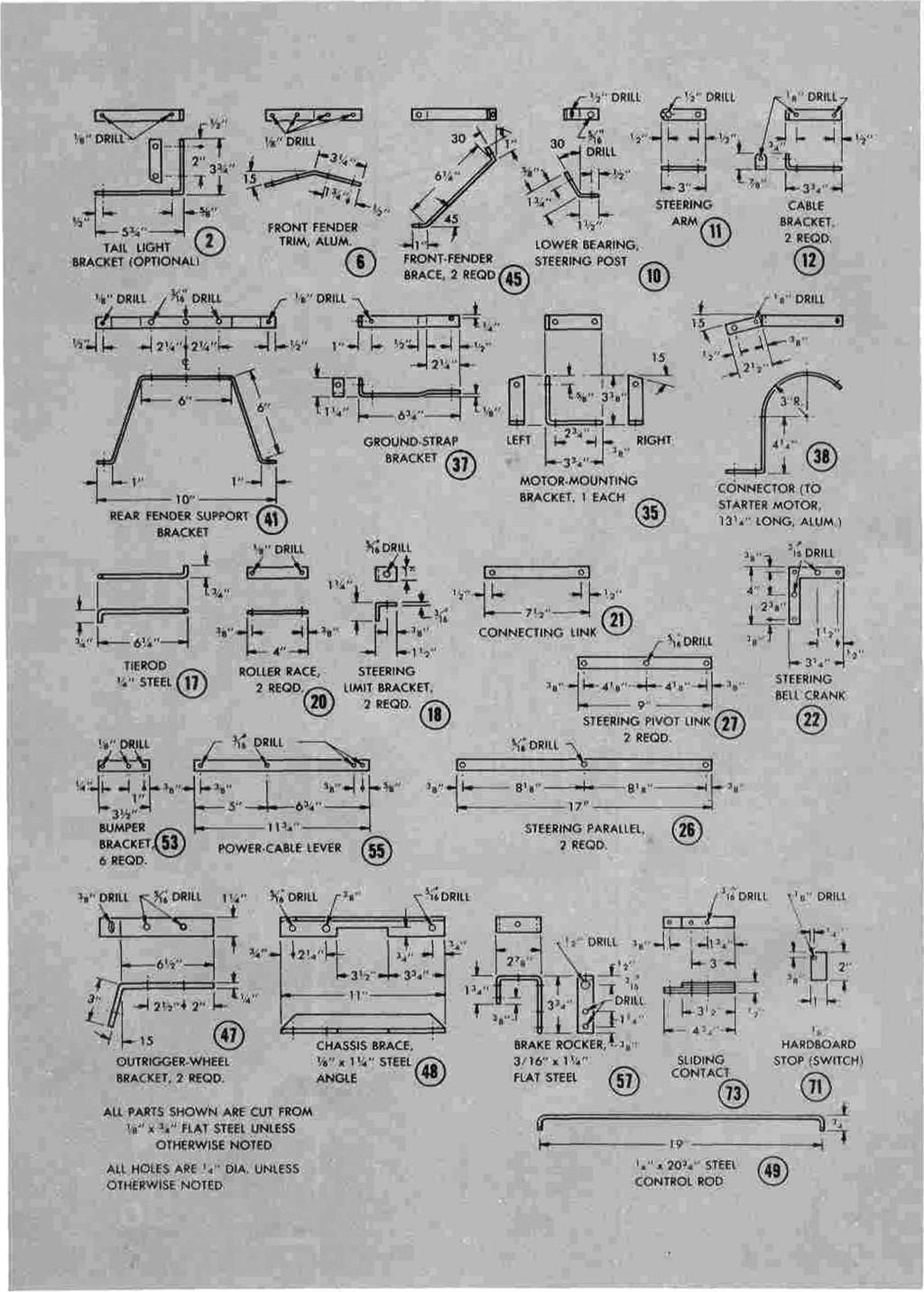
1 513 Build an electric Scoot-car Designed by ROBERT W O O L S O N Here's a sidewalk special for young hot rodders that safely takes the corner on two wheels, has two forward speed and brakes that stop on a dime This is the parallel-arm steering gear being placed in position. Pivot links are bolted to the deck, using washers and lockouts ONE FULL BATTERY CHARGE readies Scootcar for hours of fun. Cornering wheels, one on each side of the chassis, give the driver sure stability from a standing start, and a near top speed of 10 to 12 miles per hour puts the car up on two wheels where it steers and controls like a car, but rides like a speedy low-slung scooter. When cornering, the car leans over on one or the other of the outrider wheels, enabling the driver to keep safe, full control when turning. Power and brake application are controlled by pedals with strong return springs. Release the power pedal, hit the brake hard and Scoot-car stops within its length of 4 ft. Caution: While Scoot-car is a safe toy

2 1. Taillight (optional) 2. Taillight bracket 3. Rear fender 4. Seat 5. Steering wheel 6. Front-fender trim (1/2"x1/2") 7. Front lender 8. Steering post, 1/2" x 25" rod 9. Shaft collar, 1/2" dia. 10. Lower bearing, steering post 11 Steering arm 12. Cable bracket 13. Drive pedal 14. Turnbuckle 15. Drive and brake cables 16. T-hinge. 3" leaf 17. Tie rod, 1/4" steel rod 18. Steering limit bracket. 1/8" x 1" flat steel 19. Roller-race mounting block.. 1/2" x 1" x 6" hardwood 20. Roller race 21. Steering link 22. Bell crank 23. Roller, 1/2" shaft collar 24 : Wheel spindle. 1/2" x 11" rod 25; Semipneumalic wheel. 12 x 3: Steering parallel 27. Steering pivot link 28. Battery cradle 29. Cradle shim. 1/4" hardboard 30. Corrugated rubber mats 31. Battery cable 32. Plywood chassis 33. Brake band, 1/2" V-belt 34. Bumper. 1/2" thin-wall conduit 35. Motor-mounting bracket 36. Crutch tip 37. Ground-strap bracket 38. Motor terminal strap 39. Motor (auto starter) 40. Rear-fender brackets 41. Rear-fender support 42. Battery cradle 43. Battery cable 44. Fender bracket 45. Fender brace 48. Semipneumatic wheal, 6 x 1: Wheel bracket 48. Chassis cross brace 49. Control rod (pedal to switch) 50. Drive and brake cables 51. Return spring


3 52. Spring bracket 53. Bumper bracket 54. Roller-race assembly.55- power-cable lover 56. Roller-shaft bearings (hardwood) 57. Brake rocker, 1/8" x 1" steel 58. Cable clamp 59. S-hook, steel rod tooth drive sprocket 61. Roller chain tooth sprooket 63. Spacer, 4" V-pulley 64. Same as part # Same as part # 24. except 9VV 66. See part keyed # V-pulley. 6". brake drum 68. Return spring 69. Drive-wheel bearings 70. Brake rocker shaft, 1/2" x 4-3/4"" steel shafting 71. Insulator. 1/8" hardboard 72. Compression spring 73..Sliding contact arm, 74. Carbon resistor 75. Resistor brackets 76. Retainer (large washer)
4 ci /:


5 517 mechanically, there are precautions to observe ;n riding. When operating it for the first time, the immediate reaction to tipping is to take the feet off the pedals and plant them on the ground. With the car in motion, this can pitch the rider forward. The outrider wheels, of course, make lipping over impossible, and after a few trial spins, the rider will overcome the tendency to brace himself and will keep his feet on the pedals. Looking over the details you will see that Scoot-car has a unique parallel-arm steering gear and a positive roller-chain drive from an autostarter motor. Throughout the construction, full use is made of standard, readily available parts ;md materials wherever possible. For example, the steering wheel is a 1.0-in.-diameter spoked V-pulley, wrapped with electrician's tape over a length of hose set into the V-rim of the pulley. The roller-chain assures positive drive from the motor to the ground wheel. Slack In the chain should not exceed 1/2 in. Note the position of the battery cables and of the ground and power straps on the board

6 518 The brake cable is attached to the brake rocker with a cable eye and clamp. Note the end of the brake band bolted into a loop and attached to an S-hook This makes a neat, attractive wheel of just the right size. Make the plywood chassis (part No. 32) first, cutting the three openings for front and rear wheels and battery cradle as the first step. These openings should be cut just inside the pattern lines and then smoothed out to the lines with a wood rasp. Round corners slightly and sand smooth. Round the corners of the chassis to the radius indicated and sand all edges. Then lay out the hole pattern and centermark the location of holes with an awl. All smaller holes indicated are 1/4 in. in diameter. Those for the battery-cradle studs are 3/8 in. in diameter to take 3/8-in. threaded rod. Holes taking the rear-wheel bearing bolts are 5/16 in. in diameter and the two largest holes indicated take the battery cable and motor-terminal strap and are each 3/4 in. in di- The free end of the V-belt brake band is bent back on itself to form a loop taking one eye of an S-hook. The loop is secured by two bolts ameter. The two holes, indicated as elongated, take the brake and power-control cables and are drilled 1/4 in. in diameter and at as steep an angle as possible, then enlarged with a round file so that the cables clear without binding. Next comes installation of front and rear wheels. Take the front wheel first and begin by noting closely the relationship of the parts. The parallels and the pivot links arc of flat steel (also often referred to as band iron) and are cut to length and drilled as detailed. The front wheel is centered on its spindle with shaft collars, and the outer ends of the spindle are carried on rollers, which are 1/2-in. shaft collars cotter-pinned on the shaft. The spindle is drilled just inside the collars (rollers) to take the 1/4 -in. capscrews which hold the parallels to the shaft. One screw is longer to take the steering link. Spacer washers


7 519 are placed between the joining parts and all screws carry additional washers and locknuts to permit free movement. In the assembly, the rollers on the ends of the wheel spindle ride on races made as shown. Each consists of a mounting block of hardwood and a facing of flat steel, and the two units are attached to the underside of the deck with wood screws. The pivot links are bolted to the underside of the deck and the steering, or connecting, link attaches to the bell crank. The latter is bolted to the underside of the chassis and the free arm takes the lower end of the tie rod when assembled. The upper end of the tie rod is attached to the steering arm on the lower end of the steering post. The steering arm is riveted to a shaft collar which provides a hub and a means of attaching to the steering post. rear wheel attached next Now comes the rear wheel which is attached to the deck with two pillow-block bearings and carries the driven sprocket and brake drum. Notice especially the rear-wheel assembly. The brake drum is a V-pulley which slips onto the wheel spindle to which it is locked with its setscrew and additionally locked by a capscrew long enough to permit the threaded end to enter a hole drilled in the hub of the rear wheel. On the opposite side of the wheel a smaller V-pulley, with the rim cut away as indicated, serves as a spacer and a hub for the driven sprocket. It is locked to the hub of the rear wheel in the same manner as the brake drum. The brake band is a length of 1/2-in. V-belt, one end of which is attached to the top face of the deck with two wood screws. The other end is doubled back on itself to form a loop around an S-hook, the latter attaching to the brake arm. The brake rocker is carried on a shaft supported in hardwood bearings bolted to the underside of the deck. The brake-return spring attaches to the long arm of the rocker and to one of the pillow-block bearing bolts. The second S-hook attaches to the long arm of the rocker and to a cable eye which connects to the 3/16-in. wire cable from the brake pedal. Note that turnbuckles are provided on both brake and power cables for adjustment. The power-control cable reaches from the turnbuckle to one end of a pivoted lever. The other end of the lever connects to the control rod, part No. 49. The free end of the control rod is bent at right angles, drilled and cotterpinned to the sliding contact, part No. 73. The lever is returned by a spring, one end of which is hooked The lower half of the battery cradle or carrier is held in place by jam nuts. Be sure the nuts are tight Turnbuckles provide adjustment on both the power and the brake cables to a bracket screwed to the underside of the deck, see parts No. 51 and 52. The resistor, which is the carbon core from a dry cell, is mounted in brackets, parts No. 74 and 75, and is drilled and tapped for three 1/4-in. flat-head screws and two 1/4-in. capscrews, the latter holding it in place between the brackets. Drilling and tapping must be done with care, the tap holes being drilled slightly oversize so that the tap cuts only a 50- to 60-percent thread. One screw of the three shown takes the end of the battery cables, the other two, which are contacts through the resistor, are fitted with squares cut from 1/16 x 1/2- in. flat steel and center-countersunk to take the heads of the screws flush. In the off position the spring-loaded sliding contact arm contacts an insulating strip of hardboard, part No. 71, which is attached to the ground strap. This type of switch (in effect a rheostat) prevents heavy current surges and reduces arcing in the control switch to the minimum. The motor-mounting brackets are made right and left and are so placed that the regular

8 520 build a Scoot-car, continued mounting lugs on the motor can be utilized as fastenings. Note especially how the aluminum ground strap from the motor terminal is bent so that it passes through the large hole in the chassis, the lower end being held in place by the bolt on which the sliding contact pivots. It will be noted that there is an L-shaped retainer attached to one of the brackets supporting the resistor. This has been lowered in the photo for clarity. It has, however, been replaced by a large washer, part No. 76. This retainer prevents the insulator, part No. 71, from swinging. All parts of the seat except the risers are made from 3/8-in. plywood and all parts are joined with 1 x 1 x 1/2-in. steel corner angles which are readily available. Care must be taken when locating the front and side risers to see that the holes in the attaching corner angles register with those in the deck to which the seat is attached with bolts and wing nuts. Note also that the inner end of the rear fender is attached to the back of the seat with corner angles, small bolts and wing nuts. The front fender is bracketed and braced to the deck and serves not only as a front-wheel fender, but also as a support for the steering post, or column. The brake and power pedals consist of a 3-in. T-hinge and a pedal, or pad, of plywood, and a bracket which takes one eye of the turnbuckles. The hinge leaves are attached to the deck with wood screws. The bumper is a length of 1/2-in. thin-wall conduit and is held in place with six flat-steel brackets screwed to the underside of the platform with wood screws and to the thin-wall conduit with self-tapping screws or sheet-metal screws. Rubber crutch tips are slipped on the open rear ends of the bumper. It may be attached either before or after the cornering wheels are in place. These wheels are carried at an angle of 15 deg. on heavy outrigger brackets bolted to the deck. Finally, install the steel-angle brace. All that remains are installation of the battery cradle, the 6-v. battery and the foot and seat mats which are cut from corrugated-rubber stair treads and cemented to the deck. The taillight can be of the type pictured and detailed and wired into the power circuit, or you can use a battery-powered bike headlight and cover the lens with red cellophane. Also, you'll probably need to do some adjusting of the brake and power-cable turnbuckles to get the controls working right.
Amtryke Model AM-12 & AM-16
 Amtryke Model AM-12 & AM-16 Carton Contents Carefully remove and lay out all parts from the carton so as not to scratch or lose any parts or pieces. The shipping carton should contain the pictured items
EUROPEAN REAR ENGINE RIDER SERIES 20
 Parts Manual for EUROPEAN REAR ENGINE RIDER SERIES 20 MODEL E281320BE E331520KVE McDonough, GA, 30253 U.S.A. Briggs & Startton Yard Power Products Group Copyright 2006 Briggs & Startton Corporation Milwaukee,
REAR ENGINE RIDER 42 MOWER SERIES 22
 Parts Manual for REAR ENGINE RIDER MOWER SERIES MODELS 1BVE CONTENTS DESCRIPTION PAGE(S) DESCRIPTION PAGE(S) WHEELS- TIRES... - FRONT END, STEERING.... - MAIN CASE... - DIFFERENTIAL, R. H. FENDER... 8-9
Part s Catalog. GT2100 Garden Tractor. Model No. 14AP80RP744. Original Instructions (EN) (01/31/06)
 (01/31/06)") Part s Catalog GT0 Garden Tractor Model No. AP0RP Original Instructions (EN) -0 (0//0) Model P0RP -0-00 Turf Tire, x. x -0-00 Rim,.0 x.0-00 Lug Nut, /- -00A-0 Wheel Assembly, x. x -00-00 Rim Assembly,.0
Part s Catalog GT0 Garden Tractor Model No. AP0RP Original Instructions (EN) -0 (0//0) Model P0RP -0-00 Turf Tire, x. x -0-00 Rim,.0 x.0-00 Lug Nut, /- -00A-0 Wheel Assembly, x. x -00-00 Rim Assembly,.0
REAR ENGINE RIDER EUROPEAN SERIES 22
 Parts Manual for REAR ENGINE RIDER EUROPEAN SERIES 22 MODELS E2822BE E2822BE E1522KVE CONTENTS DESCRIPTION PAGE(S) DESCRIPTION PAGE(S) WHEELS, TIRES...2, DRIVE DISC ASSEMBLY... 22 FRONT END, STEERING...4,
SIDEWALK PLAY CAR 174 POPULAR MECHANICS
 SIDEWALK PLAY CAR L By Elmer V. Clark IVELY youngsters and craftsman fathers alike will get a thrill out of this tiny play car, which looks and drives like a real automobile except that it's scaled down
Retriever 5100G/P. 11/89 revised 10/02 FORM NO
 Retriever 5100G/P PARTS LIST Advance MODELS 56497000, 56497010 This parts list is for machines after serial number 353005 All models covered in this manual are OBSOLETE 11/89 revised 10/02 FORM NO. 56042216
Assembly Manual. 1/10th Formula 1 Car
 Assembly Manual 1/10th Formula 1 Car Center Pivot Bag 1 3374 - Center Pivot Socket 40194 - Hard Anodized Alum Pivot ball 3254-2-56 *Note - Sometimes it is helpful to slightly over-tighten the top clamp
MODEL S-32, 3200, ALL AMERICAN
 MODEL S-32, 3200, ALL AMERICAN 1. 1 3201-7001 Chassis Weldment 2. 1 3204-7010 Bell Crank Weld 3. 1 3204-7009 Seconday Lift Weld 4. 1 3204-2018 Primary Lift Arm 6. 1 340-3025-S0 Seat Spring 6. 3 847-2803
THE SCIENCE & MECHANICS half-size antique
 Build it to scale: THE SCIENCE & MECHANICS half-size antique truck with its 2-hp, 4-cycle gasoline engine makes a really sensational toy for a youngster. It will carry Junior around the lot at a brisk
Safety - Installation and Operation:
 4x4 or 4x2 Instructions EZGO Electric Cars Thank you for purchasing your 4x4 or 4x2 conversion kit. Safety at all times whether during installation or operation is utmost importance. Before After!!!!!!!!!!!!!!
Parts Manual for LAWN TRACTORS MANUAL CLUTCH HYDRO DRIVE SERIES F MODELS LT145H33FBV LT145H38FBV ELT145H33FBV
 Parts Manual for LAWN TRACTORS MANUAL CLUTCH HYDRO DRIVE SERIES F MODELS LT145H33FBV LT145H38FBV ELT145H33FBV IT IS THE POLICY OF SNAPPER TO IMPROVE ITS PRODUCTS WHENEVER IT IS POSSIBLE AND PRACTICAL TO
REAR ENGINE RIDER SERIES 22
 Parts Manual for REAR ENGINE RIDER SERIES 22 MODELS 280922B W280922B 2822BE 281222BE 00922B 022BE W022BE 01222BE 14522BVE 1522KVE IT IS THE POLICY OF SNAPPER TO IMPROVE ITS PRODUCTS WHENEVER IT IS POSSIBLE
SECTION V ASSEMBLY CAUTION THE FOLLOWING SAFETY PRECAUTIONS SHOULD BE THOROUGHLY UNDERSTOOD BEFORE ATTEMPTING MACHINE ASSEMBLY.
 SECTION V ASSEMBLY CAUTION THE FOLLOWING SAFETY PRECAUTIONS SHOULD BE THOROUGHLY UNDERSTOOD BEFORE ATTEMPTING MACHINE ASSEMBLY. 1. Wear personal protective equipment such as, but not limited to protection
13AU609H063 (1999) Page 1 of 25 Axle & Wheels Front And Steering Assembly
 Page 1 of 25 Axle & Wheels Front And Steering Assembly") 13AU609H063 (1999) Page 1 of 25 Axle & Wheels Front And Steering Assembly 13AU609H063 (1999) Page 2 of 25 Axle & Wheels Front And Steering Assembly 1 683-0304 1 S Frame 2 710-0604A 1 /P Self-tapping Screw,
13AU609H063 (1999) Page 1 of 25 Axle & Wheels Front And Steering Assembly 13AU609H063 (1999) Page 2 of 25 Axle & Wheels Front And Steering Assembly 1 683-0304 1 S Frame 2 710-0604A 1 /P Self-tapping Screw,
Hydrostatic Zero-Turn Commercial Riding Mower
 Hydrostatic Zero-Turn Commercial Riding Mower Professional Turf Equipment 54" Fabricated Deck ILLUSTRATED PARTS LIST TABLE OF CONTENTS Frame Assembly.................................. 3 54" Fabricated
TECHNICAL DATA BROCHURE ZTR 308/3II
 Date 8/84 Page 1 of 6 TECHNICAL DATA BROCHURE ZTR 308/3II IMPORTANT - READ OPERATOR'S MANUAL BEFORE OPERATION OR MAKING ADJUSTMENTS. ' Seat Adjustment Loosen bolts on sliding brackets under each side of
TECHNICAL DATA BROCHURE - ZTR 424 & 427 DATE 8/85 PAGE 1 OF 8
 TECHNICAL DATA BROCHURE - ZTR 424 & 427 DATE 8/85 PAGE 1 OF 8 IMPORTANT - READ OPERATOR'S MANUAL BEFORE OPERATION OR MAKING ADJUSTMENTS Deluxe Seat Adjustment Easy hand lever action allows forward and
Autodrive Lawn Tractor
 Illustrated Parts Manual Autodrive Lawn Tractor MTD LLC, P.O. BOX CLEVELAND, OHIO -009 Printed In USA Form No. 9-00 (September, 2009) Steering & Front Axle Assembly 2 9 0 2 9 2 20 9 2 20 2 22 2 2 2 2 2
TECHNICAL DATA BROCHURE ZTR 426
 TECHNICAL DATA BROCHURE ZTR 426 Date 8/84 IMPORTANT - READ OPERATOR'S MANUAL BEFORE OPERATION. Page 1 of 6 Seat Adjustment Loosen bolts on sliding bracket under each side of seat, slide seat forward or
CS340ES. Property of - Not for Resale A1
 A1 CYLINDER HEAD - CYLINDER 1 8G8-11111-00-00 HEAD, CYLINDER 1......... 1 2 8G8-11121-00-00 HEAD, CYLINDER 2......... 1 3 NGK-BR9ES-00-00 PLUG, SPARK............. 2 4 8G8-11181-01-00 GASKET, CYLINDER HEAD
Models 820 and 840 2
 Models 820 and 840 2 Models 820 and 840 1 783-0250 Hood 2 738-0952 Shld. Bolt.375" Dia. x.5" 3 736-0175 Spr. Washer.265" I.D. x.562" OD 4 710-0751 Hex Bolt 1/4-20 x.62" * 6 7-0271 Hex Sems Nut 1/4-20 Thd.
Hydrostatic Zero-Turn Commercial Riding Mower
 Hydrostatic Zero-Turn Commercial Riding Mower Professional Turf Equipment 0" Fabricated Deck ILLUSTRATED PARTS LIST TABLE OF CONTENTS Frame Assembly.................................. 3 0" Fabricated Cutter
LAWN TRACTORS MANUAL CLUTCH HYDRO DRIVE SERIES "G"
 Parts Manual for LAWN TRACTORS MANUAL CLUTCH HYDRO DRIVE SERIES "G" MODEL ELT145H33GBV LT145H33GBV LT145H38GBV LT150H38GKV WLT145H38GKV McDonough, GA, 30253 U.S.A. COPYRIGHT 2006 SNAPPER PRODUCTS, INC.
465606x692A Lawn Tractor (2001) Page 1 of 25 Drive Assembly
 Page 1 of 25 Drive Assembly") 465606x692A Lawn Tractor (2001) Page 1 of 25 Drive Assembly 465606x692A Lawn Tractor (2001) Page 2 of 25 Drive Assembly 1 26X249 Screw 2 095315 Knob, Parking Brake 3 711691 Nut, Push 4 1001217 Z Rod, Parking
465606x692A Lawn Tractor (2001) Page 1 of 25 Drive Assembly 465606x692A Lawn Tractor (2001) Page 2 of 25 Drive Assembly 1 26X249 Screw 2 095315 Knob, Parking Brake 3 711691 Nut, Push 4 1001217 Z Rod, Parking
INSTRUCTION S G-Comp Front Suspension: Chevy Nova Speedway Motors, Inc. 2017
 INSTRUCTION S 350-100 G-Comp Front Suspension: 62-67 Chevy Nova Speedway Motors, Inc. 2017 Kit Contents: 91035700 G-Comp Bare Subframe 350101 G-Comp Support Tubes 91035702 G-Comp Front Subframe Hardware
CALIFORNIA TRIMMER MOWER MAINTENANCE MANUAL
 CALIFORNIA TRIMMER MOWER MAINTENANCE MANUAL 2 Table of Contents Section 1: General Information Page Handle Assembly Instructions 4 Maintenance All Models 6 Oil Change Procedures All Models 9 Height Adjustment
MODEL x692A REPAIR PARTS HOOD & GRILL
 MODEL 0xA HOOD & GRILL 0 0 0 0 0 0 0 0 MODEL 0xA Screw x0 Dash 00 Trim. 00 Cable Hood Assemnly 00E00 Screw x Lens & Reflector Assembly Cap, Pivot 0 Bolt, Shoulder x 0 Base, Pivot 0 Brace, Right Grille
TT6101 Rotary Tedder
 TT0 Rotary Tedder 0/0/0 Illustrated Parts Breakdown Page Chassis Assembly Page Page Transport Axle Assembly S/N - Transport Axle Assembly S/N + Page Page Page Page Page Transport Lock Assembly Lift Frame
R O A D S M I T H TRIKE CONVERSIONS BY THE TRIKE SHOP
 R O A D S M I T H TRIKE CONVERSIONS BY THE TRIKE SHOP Please thoroughly review the instructions before and during installation. Keep in mind that this product was designed to be installed by trained dealer
PARTS MANUAL THIS PAGE INTENTIONALLY LEFT BLANK. Ag-Bag International, Ltd. G7000 June Appendix A
 The parts manual is organized into groups, it is designed to make the locating of parts easier. The exploded drawings also show assembly paths. All parts listed are available from your authorized Ag-Bag
365L (2001) Page 1 of 36 54" Deck Assembly
 Page 1 of 36 54 Deck Assembly") 365L (2001) Page 1 of 36 54" Deck Assembly 365L (2001) Page 2 of 36 54" Deck Assembly 1 720-0241 1 S Wing Nut Knob 2 703-2817 1 Belt Cover LH 3 703-2816 1 Belt Cover RH 4 747-3306 1 Idler Spring Mounting
365L (2001) Page 1 of 36 54" Deck Assembly 365L (2001) Page 2 of 36 54" Deck Assembly 1 720-0241 1 S Wing Nut Knob 2 703-2817 1 Belt Cover LH 3 703-2816 1 Belt Cover RH 4 747-3306 1 Idler Spring Mounting
S/N 1H019H - 1H310H Page 1 of 33 46" Cutting Deck Assembly
 1180 S/N 1H019H - 1H310H Page 1 of 33 46" Cutting Deck Assembly 1180 S/N 1H019H - 1H310H Page 2 of 33 46" Cutting Deck Assembly 1 17982 1 S Reinforcement Spindle Plate 2 618-0430 1 S Spindle Assembly w/
Slide the billet aluminum cap over the bushing and secure with the 3/8-16 x 2 1/2 socket head allen and locknuts provided.
 Slide the billet aluminum cap over the bushing and secure with the 3/8-16 x 2 1/2 socket head allen and locknuts provided. Put the urethane bushings into the upper antiroll-bar-link eyebolt. Coat the bushings
Land Cruiser FJ80 and FZJ80 Double Swingout Rear Bumper Installation Instructions PRELIMINARY
 Land Cruiser FJ80 and FZJ80 Double Swingout Rear Bumper Installation Instructions Fits 1991-1997 80 Series Land Cruiser / Lexus LX450 PRELIMINARY Thank you for purchasing a Rear Bumper for your Land Cruiser.
14A6816H190 GT-2150 (2003) Page 1 of 28 Carburetor
 Page 1 of 28 Carburetor") 14A6816H190 GT-2150 (2003) Page 1 of 28 Carburetor 14A6816H190 GT-2150 (2003) Page 2 of 28 Carburetor TC-640221 1 /P Carburetor (Incl 184 of Engine Parts Lists) 1 TC-640216 1 Throttle Shaft & Lever Assembly
14A6816H190 GT-2150 (2003) Page 1 of 28 Carburetor 14A6816H190 GT-2150 (2003) Page 2 of 28 Carburetor TC-640221 1 /P Carburetor (Incl 184 of Engine Parts Lists) 1 TC-640216 1 Throttle Shaft & Lever Assembly
AmTryke Adult Recumbent Model HP1000 #50-HC-1000
 AmTryke Adult Recumbent Model HP1000 #50-HC-1000 TOOLS Needed for Assembly 5 mm Allen Wrench 8 mm Socket or Wrench 10 mm Socket or Wrench 14 mm Socket or Wrench 15 mm Socket or Wrench 22 mm Socket or Adjustable
Retriever 5800G/P/D. revised 2/01 Form Number
 Retriever 5800G/P/D PARTS LIST Advance MODELS 56482005, 56482010, 56482015 This parts list is for machines after serial number 221134 All models covered in this manual are OBSOLETE revised 2/01 Form Number
A1062 & A1072 AUGER ASSEMBLY MANUAL. Read & understand all instructions pertaining to this auger prior to use!
 A1062 & A1072 AUGER ASSEMBLY MANUAL Read & understand all instructions pertaining to this auger prior to use! Safety Alert Watch for this ALERT Symbol. It identifies potential hazards to Personal SAFETY
250P Manure Spreader
 0P Manure Spreader Illustrated Parts Breakdown Page - Page Page Page Page Page Page Page Page Page Page Page Page Page Page - Page Page Page 0 Complete Front End PTO/Jack/Hitch Assembly Front Pulley Assembly
LIFT-507 BMF Lift Kit E-Z-Go RXV Gas or Electric Installation Instructions
 LIFT-507 BMF Lift Kit E-Z-Go RXV Gas or Electric Installation Instructions Contents of LIFT-507 E-Z-Go RXV BMF Lift Kit: a (1 ea.) BMF A-Arm Assembly b (1 ea.) Driver Side Shock Tower c (1 ea.) Passenger
MODEL x99A REPAIR PARTS SEAT DECK
 MODEL 0xA F 00L SEAT DECK 0 0 0 0 MODEL 0xA 0 Seat 0E0 Support, Seat 0x Push On Cap 0x Z Washer 000 Bolt, Wing 00x Bolt 00E0 Bracket, Pivot 0X Nut x Screw 0 00 Spring, Leaf x Spring 0 Z Washer, Cup 00x
Champion Series Zero-Turn Riders & Mower Decks
 Parts Manual Champion Series Zero-Turn Riders & Mower Decks HP Tractors Mfg. No. Description Champion, HP Zero-Turn Rider Champion, HP Zero-Turn Rider (CE) 0HP Tractors Mfg. No. Description Champion, 0HP
Bag 1. Bag 1. Center Pivot. Center Pivot
 8 00734 01901 5 Center Pivot Bag 1 3374 - Center Pivot Socket 4019 - Alum Pivot ball 3254-2-56 Button Head *Note - Sometimes it is helpful to slightly over-tighten the top clamp screws, then work the ball
55-64 Full Size Chevy
 55-64 Full Size Chevy Installation Instructions Power Disc Conversion 9 slimline booster pictured Your new disc brake conversion kit can be bolted up with standard hand tools. The only tools you may not
Automatic Lawn Tractor Model Series 600
 Illustrated Parts Manual utomatic Lawn Tractor Model Series 00 MTD LLC, P.O. BOX 11 CLEVELND, OHIO -00 Printed In US Form No. -08 (February 18, 008) Fender, Deck Lift & Seat 5 5 Models w/ Manually djusting
Automatic Lawn Tractor Model Series 600
 Illustrated Parts Manual Automatic Lawn Tractor Model Series 600 MTD LLC, P.O. BOX 6 CLEVELAND, OHIO 6-009 Printed In USA Form No. 69-09 (January 8, 008) -Style Fender, Deck Lift & Seat 6 6 0 8 On some
90 Utility Model Number A2013KUB2BUSZ SHARE OUR PASSION.
 2013 90 Utility Model Number A2013KUB2BUSZ TM SHARE OUR PASSION. TABLE OF CONTENTS 2013 ATV 90 (Model No. A2013KUB2BUSZ) BODY PANEL AND HEADLIGHT ASSEMBLY... 1 FRONT AND REAR RACK ASSEMBLY... 2 FRAME AND
TT8101 Rotary Tedder
 TT0 Rotary Tedder Illustrated Parts Breakdown Page Front End Page Page Transport Axle Assembly Cylinder Linkage Page Guards Page Page Page Page Transport Lock Assembly Lift Frame Assembly Center Tunnel
... TX-L MODEL NUMBER CONTENTS 2-3 BODY. 4-6 HOOD ASSEMBLY IGNITION ASSEMBLY. 8-9 SEAT ASSEMBLY STEERING ASSEMBLY.
 .. ~ : l~ :;~, ~ 0 J-I-'olaris I I '. ... TX-L MODEL NUMBER 080639 CONTENTS BODY. HOOD ASSEMBLY IGNITION ASSEMBLY. SEAT ASSEMBLY... STEERING ASSEMBLY. CHAINCASE ASSEMBLY. DRIVE CLUTCH. DRIVEN CLUTCH. DRIVE
Retriever PARTS LIST Advance MODEL 5200G(OBSOLETE)
") Retriever PARTS LIST Advance MODEL 5200G(OBSOLETE) 5/85 revised 2/01 FORM NO. 56042131 TABLE OF CONTENTS DESCRIPTION PAGE OUTER BODY...1-2 HYDRAULIC PUMP, ENGINE & FUEL TANK...3-4 HYDRAULIC OIL FILTER,
Retriever PARTS LIST Advance MODEL 5200G(OBSOLETE) 5/85 revised 2/01 FORM NO. 56042131 TABLE OF CONTENTS DESCRIPTION PAGE OUTER BODY...1-2 HYDRAULIC PUMP, ENGINE & FUEL TANK...3-4 HYDRAULIC OIL FILTER,
Parts Manual. ProCut 20 Series 3-Wheel Riding Mower Serial No & Above. Models: H2220K R52 R61
 Parts Manual ProCut 20 Series 3-Wheel Riding Mower Serial No. 7671 & Above Models: H2220K R52 R61 Ferris Industries 5375 North Main Street Munnsville, NY 13409 USA 800-933-6175 5022204 Revision 07 Rev.
Part s Catalog. LX500 Lawn Tractor. Model No. 13AP60RP744. Original Instructions (EN) (01/31/06)
 (01/31/06)") Part s Catalog For Parts Call 0-- or 0-- LX00 Lawn Tractor Model No. AP0RP Original Instructions (EN) -0 (0//0) For Parts Call 0-- or 0-- Model P0RP NUMBER --00 Turf Tire, 0 x 0.0 x -000-00 Rim,.0 x.0-0-0
Part s Catalog For Parts Call 0-- or 0-- LX00 Lawn Tractor Model No. AP0RP Original Instructions (EN) -0 (0//0) For Parts Call 0-- or 0-- Model P0RP NUMBER --00 Turf Tire, 0 x 0.0 x -000-00 Rim,.0 x.0-0-0
SPARE PARTS LIST RIDERS R322T AWD, , , ,
 SPARE PARTS LIST RIDERS R322T AWD, 966785801, 967032101, 967153001, 2012-03 103CM CUTTING DECK R322T AWD, 966785801, 967032101, 967153001, 2012-03 103CM CUTTING DECK R322T AWD, 966785801, 967032101, 967153001,
Parts Manual Rev. B RZT48 /
 115 91 36-2 Rev. B Parts Manual RZT48 / 96 62001-00 Please read the operator manual carefully and make sure you understand the instructions before using the machine. Gasoline containing a maximum of 10%
ATV 90 UTILITY GREEN (A2006KUB2BUSG) Page 1 of 60 AIR INTAKE ASSEMBLY
 Page 1 of 60 AIR INTAKE ASSEMBLY") 2006 ATV 90 UTILITY GREEN (A2006KUB2BUSG) Page 1 of 60 AIR INTAKE ASSEMBLY 2006 ATV 90 UTILITY GREEN (A2006KUB2BUSG) Page 2 of 60 AIR INTAKE ASSEMBLY Ref # Part Number Qty S/P/F Description 1 3303-005
2006 ATV 90 UTILITY GREEN (A2006KUB2BUSG) Page 1 of 60 AIR INTAKE ASSEMBLY 2006 ATV 90 UTILITY GREEN (A2006KUB2BUSG) Page 2 of 60 AIR INTAKE ASSEMBLY Ref # Part Number Qty S/P/F Description 1 3303-005
Section 13. Tail Rotor Drive. RotorWay International A600 TALON Construction Manual. Section 13. Page A
 RotorWay International Page A Tail Rotor Drive Procedures covered in this section: Install driveshafts and gearboxes; install drive belt and tensioner; fabricate and install tail rotor pitch actuator arms;
STOP---READ THIS FIRST!
 STOP---READ THIS FIRST! **Read These Entire Instructions Before Starting Anything** 2007-2010 GM 1500 TRUCK LIFT KIT INSTRUCTIONS (PART# 50700 & 50720) 5680 W. Barstow, Fresno, CA 93722 PH: (559) 226-8196
SPARE PARTS LIST RIDERS R220T, , , ,
 SPARE PARTS LIST RIDERS R220T, 966785701, 967032001, 967150901, 103CM CUTTING DECK R220T, 966785701, 967032001, 967150901, 103CM CUTTING DECK R220T, 966785701, 967032001, 967150901, Ref Part no. Description
LoD Offroad. Jeep JK Door Linked Rear Bumper with Tire Carrier Installation Instructions
 LoD Offroad Jeep JK Door Linked Rear Bumper with Tire Carrier Installation Instructions Please read through the instructions before beginning any part of the installation process. Packaging List: 1-Rear
R O A D S M I T H TRIKE CONVERSIONS BY THE TRIKE SHOP
 R O A D S M I T H TRIKE CONVERSIONS BY THE TRIKE SHOP Please thoroughly review the instructions before and during installation. Keep in mind that this product was designed to be installed by trained dealer
REAR ENGINE RIDER SERIES 16 & 18
 Parts Manual for REAR ENGINE RIDER SERIES 16 & 18 MODELS 20816B N20816B 20816BE N20816BE 281016BE 2818BE N281016BE 301016BE 301216BE 3018BE 3316BVE 3318BVE 3316KVE 33118KVE IT IS THE POLICY OF SNAPPER
Model 3050 Installation Instructions. Model 3050 Electric Wall Installation Procedure
 Model 3050 Electric Wall Installation Procedure Effective August 2017 Special tools needed: Bondus type hex ball point tip Allen 7/32 Roller Chain tensioner Roller Chain breaker 1 7/8 open end wrench 15/16
37A- S/N 350,000 Up. Turbine Drive Water-Reels. Engine Drive Slurry-Reels T37A E37A. Parts Manual. Serial No. 350, ,999
 37A- S/N 350,000 Up Turbine Drive Water-Reels Engine Drive Slurry-Reels T37A E37A Parts Manual Serial No. 350,000-359,999 700 S. Schrader Ave. Havana, Illinois 62644 Phone: 309-543-4425 Fax: 309-543-4945
SIDEWINDER 350 INSTALLATION INSTRUCTIONS & OPERATION MANUAL NOVEMBER 2011
 SIDEWINDER 350 INSTALLATION INSTRUCTIONS & OPERATION MANUAL NOVEMBER 2011 PATENT PENDING Donovan Enterprises 3353 SE Gran Park Way, Stuart FL 34997 800-327-8287 www.donovan-ent.com PACKING LIST FOR SIDEWINDER
Adult Car Plans. A comprehensive guide to help you build an official Soap Box Derby Adult Car
 Adult Car Plans A comprehensive guide to help you build an official Soap Box Derby Adult Car 1 Table Of Contents Introduction...Page 3 Adult Car Floorboard...Page 4 Step One Steering Stop Installation...Page
PIÈCES DÉTACHÉES ELT125D33 1KV. Tondeuse autoportée
 PIÈCES DÉTACHÉES Tondeuse autoportée ELT15D33 1KV Yvan Béal - 1, av. de l Agriculture - B.P. 16 Z.I. du Brézet - 63014 Clermont-Ferrand Cedex Tél : 04 73 91 93 51 - Télécopie : 04 73 90 3 11 www.yvanbeal.fr
COUNTER SHAFT NUT LOCKING PLATE 1 $ HOIST DRUM CLUTCH EYE BOLTS 1 $ LEFT DRUM CLUTCH THREADED PIN 2 $ 138.
 1 2184 PULLEY FOR RADIATOR FAN 1 $ 326.25 2 2184 PULLEY FOR RADIATOR FAN 1 $ 326.25 3 3331 REAR DRUM BRAKE RETURN SPRING 5 $ 51.31 5 10285 LEFT REAR DRUM BRAKE AIR CAN REACH ROD ( LONG ROD ) 1 $ 85.12
RJS2021 LTO SPORT OVAL RACER LESS ELECTRICS
 RJS2021 LTO SPORT OVAL RACER LESS ELECTRICS THANKS FOR BUYING THE RJ SPEED 1/10 LTO SPORT KIT FOR OVAL RACING. THE ASSEMBLY WILL NOT BE DIFFICULT IF YOU READ THE TEXT, LOOK AT THE PICTURES, AND THE EXPLODED
AC 120 MODEL NUMBER S2008ACAAAUSG MODEL NUMBER S2008ACAAAUSP
 2008 AC 120 Illustrated Parts Manual MODEL NUMBER S2008ACAAAUSG MODEL NUMBER S2008ACAAAUSP TABLE OF CONTENTS (Model No. S2008ACAAAUSG) (Model No. S2008ACAAAUSP) SKI AND SPINDLE ASSEMBLY... 1 A-ARM ASSEMBLY...
INSTALLATION GUIDE Bolt-On Drag-Race Strut Clip Chevy II
 INSTALLATION GUIDE 7702 Bolt-On Drag-Race Strut Clip 1962-67 Chevy II Description: STRUT CLIP 4130 BOLT ON 62-67 CHEVY II, INCLUDES 4130 ROUND TUBE FRAME CLIP, DOUBLE-ADJUSTABLE STRUTS, ADJUSTABLE-HEIGHT
TG/RB/2M/Web Rev.12/1/16. Pipe Hangers & Devices
 TG/RB/2M/Web Rev.12/1/16 Pipe Hangers & Devices Pipe Welcome Hangers to PHD & Devices Manufacturing PHD Manufacturing, Inc. was founded in 1972 by a group of industry veterans with strong management, financial,
INSTALLATION INSTRUCTIONS
 INSTALLATION INSTRUCTIONS INSTALLATION INSTRUCTIONS THESE INSTRUCTIONS COVER THE INSTALLATION OF THE FOLLOWING REAR DOORS WITH OUTSIDE CABLES AND MAXIMUM SECURITY LOCK: 3/4" and 1" DryFreight TODCOLD Insulated
Installation Instructions LamboStyleDoors (The instruction are to be used as a reference. Please repeat for both doors)
") Installation Instructions LamboStyleDoors (The instruction are to be used as a reference. Please repeat for both doors) Pre installation check list: - Double check vehicles data with TUV certificate -
Installation Instructions LamboStyleDoors (The instruction are to be used as a reference. Please repeat for both doors) Pre installation check list: - Double check vehicles data with TUV certificate -
MODEL 40507x8C REPAIR PARTS CHASSIS & HOOD
 MODEL 007xC CHASSIS & HOOD 2 3 7 9 2 9 2 2 2 27 2 29 32 3 3 37 3 0 39 2 3 7 3 MODEL 007xC CHASSIS & HOOD Seat 90 2 Cap, Push 0n 2x 3 Spring 907 Screw 2x9 Bolt, Wing 0 Washer x7 7 Bolt, Shoulder 9x Support,
INSTALLATION INSTRUCTIONS
 INSTALLATION INSTRUCTIONS Document# 19-0038 2004+ Lotus Elise (Series 2) Rear Clamshell Removal Kit Safely support the vehicle. This is a two-person job. Allow 1 to 2 hours for initial disassembly. Have
Drive End Bracket & Bearing. Drive End Bracket. Tandem Axle # #865733
 Drive End Bracket & Bearing #865089 1 06409700 1" Lock Collar 2 865733 Drive Bracket w/ Bearing 3 310037 End Drive Shaft Drive End Bracket #865733 1 03003100 Bearing 1" w/snap Ring 2 957795 Drive End Bracket
First, check and record the camber and caster readings, they will be adjusted later.
 First, check and record the camber and caster readings, they will be adjusted later. The caliper-mounting bosses are machined perpendicular to the spindle so they are an excellent place for the level.
Parts Manual for PRO GEAR EXPRESS MID-SIZE WALK BEHIND MOWERS SERIES 0 & 1 POWER UNIT MODEL SPE1250KW SPE140KW SPE150KH SPE151KW SPEL150KH
 Parts Manual for PRO GEAR EXPRESS MID-SIZE WALK BEHIND MOWERS SERIES 0 & 1 POWER UNIT MODEL SPE10KW SPE0KW SPE10KH SPE11KW SPEL10KH MOWER UNIT MODEL SPE30 SPE480 SPE31 SPE481 IT IS POLICY OF SNAPPER TO
Amtryke Model Snappy #
 Amtryke Model Snappy #50-0150 Carton Contents Carefully remove and lay out all parts from the carton so as not to scratch or lose any parts or pieces. The shipping carton should contain the pictured items
AmTryke Adult Recumbent Model JT2000 #50-FC-2000
 AmTryke Adult Recumbent Model JT2000 #50-FC-2000 TOOLS Needed for Assembly 5 mm Allen Wrench 8 mm Socket or Wrench 10 mm Socket or Wrench 14 mm Socket or Wrench 15 mm Socket or Wrench 22 mm Socket or Adjustable
52100x92A Garden Tractor (1999) Page 1 of 25 Blade Drive
 Page 1 of 25 Blade Drive") 52100x92A Garden Tractor (1999) Page 1 of 25 Blade Drive 52100x92A Garden Tractor (1999) Page 2 of 25 Blade Drive 1 094607E700 Cover, Right Pulley 2 26X250MA Screw 3 015X84MA Nut 4 037X92MA Belt, Secondary
52100x92A Garden Tractor (1999) Page 1 of 25 Blade Drive 52100x92A Garden Tractor (1999) Page 2 of 25 Blade Drive 1 094607E700 Cover, Right Pulley 2 26X250MA Screw 3 015X84MA Nut 4 037X92MA Belt, Secondary
CYLINDER HEAD - CYLINDER
 A1 CYLINDER HEAD - CYLINDER 1 8AY-11111-00-00 HEAD, CYLINDER 1......... 1 2 8A7-12499-00-00 JOINT................... 1 3 NGK-BR9ES-00-00 PLUG, SPARK............. 2 4 8AY-11181-00-00 GASKET, CYLINDER HEAD
S/N 1H019H - 1H310H Page 1 of 48 42" Cutting Deck Assembly
 1170 S/N 1H019H - 1H310H Page 1 of 48 42" Cutting Deck Assembly 1170 S/N 1H019H - 1H310H Page 2 of 48 42" Cutting Deck Assembly 4 683-0254 1 S Deck Adjustment Bracket w/ Weld Nut 9 710-0528 1 /P Hex Cap
Marine Engineering Exam Resource Review of Couplings
 1. What are rigid couplings used for? Used to join drive shafts together. True alignment and rigidity are required. Example Drive shafts and production lines, bridge cranes, solid shaft that needs to be
Installation Instructions. QuickSilver Shifter. Fits: GM, Ford, Chrysler Transmissions See Application Guide for Specific Applications Part # 80683
 Installation Instructions QuickSilver Shifter Fits: GM, Ford, Chrysler Transmissions See Application Guide for Specific Applications Part # 80683 WORK SAFELY! For maximum safety, perform this installation
MK-5000G exploded VieW
 Frame accessories 38 cutting head Pump Assembly 39 connecting linkage foot pedal linkage 40 curtain blade guard 41 ENGINE Assembly 42 PARTS LIST A Frames - - A1 Frame, MK-5000 Main 1 155541 B Pivot Bracket
R O A D S M I T H TRIKE CONVERSIONS BY THE TRIKE SHOP
 R O A D S M I T H TRIKE CONVERSIONS BY THE TRIKE SHOP Please thoroughly review the instructions before and during installation. Keep in mind that this product was designed to be installed by trained dealer
INSTALLATION INSTRUCTIONS 97 FORD EXPEDITION
 INSTALLATION INSTRUCTIONS 97 FORD EXPEDITION 1. Read the instructions completely and carefully before you begin. Check the kit for proper contents (refer to the part s list and the picture diagrams). Before
Next, set the bar level and tighten it down. Do this on both the driver and passenger sides.
 Next, set the bar level and tighten it down. Do this on both the driver and passenger sides. Using two tape measures, measure the outside width at the front and the rear of the tubes. The front dimension
PARTS LIST CHAMP 2929
 PARTS LIST CHAMP 2929 1 ITEM PART NO. DESCRIPTION QTY. 101 9122343 3/8-16 X 2 HEX HEAD FULL THREADED BOLT 3 102 9122100 3/8 SPLIT LOCK WASHER 3 103 9121400 3/8 I.D. X 7/8 O.D. X.064/.104 THICK WROUGHT
Chevy Nova Pro-Touring Front Suspension Installation Instructions
 1962-1967 Chevy Nova Pro-Touring Front Suspension Installation Instructions 1-800-984-6259 www.totalcostinvolved.com 1 Pro-Touring Clip A-Arm Assembly Sway Bar Assembly Fender Panel Kit 8 7/16-20 * 1 ¼
Parts List. Model Revision 00 TP LT-R
 Parts List Model 7800276 Revision 00 Rev. Date 03/2008 Table Of Contents PRODUCT COMPONENTS PAGES Steering... 4 Engine Mount... 6 Motion Drive... 8 Electrical System... 12 Chassis & Hood... 14 Decals...
2014 GM 1500 TRUCK STOP---READ THIS FIRST! 7" Lift KIT. **Read These Entire Instructions Before Starting Anything**
 STOP---READ THIS FIRST! **Read These Entire Instructions Before Starting Anything** 2014 GM 1500 TRUCK LIFT KIT INSTRUCTIONS (PART #50768 & #50769 ) 5680 W. Barstow, Fresno, CA 93722 PH: (559) 226-8196
 DRUM BRAKE RIMS Periodic inspection of drum brake rims is necessary to determine indications of uneven or excessive wear. In general, brake rim failures other that regular wear are caused by brake linings
230 & 3400 Gravity Wagons & Accessories
 OPERATORS MANUAL & PARTS BOOK 230 & 3400 Gravity Wagons & Accessories 1050 E. COLUMBIA P.O. BOX 168 ARTHUR, IL 61911 TOLL FREE: 800-677-2802 PHONE: 217-543-3471 WWW.E-ZTRAIL.COM WARNINGS, INSTRUCTIONS
Parts Manual PZ Please read the operator manual carefully and make sure you understand the instructions before using the machine.
 Parts Manual PZ 60 967 045601-00 Please read the operator manual carefully and make sure you understand the instructions before using the machine. When you need spare parts or support in service questions,
DVX 90 MODEL NUMBER A2008KSB2BUSD (BLACK-RED) MODEL NUMBER A2008KSB2BUSE (BLACK-CAT GREEN) MORE TO GO ON. TM
 MODEL NUMBER A2008KSB2BUSE (BLACK-CAT GREEN) MORE TO GO ON. TM") 2008 DVX 90 Illustrated Parts Manual MODEL NUMBER A2008KSB2BUSD (BLACK-RED) MODEL NUMBER A2008KSB2BUSE (BLACK-CAT GREEN) MORE TO GO ON. TM TABLE OF CONTENTS Black-Red (Model No. A2008KSB2BUSD) Black-Cat
2008 DVX 90 Illustrated Parts Manual MODEL NUMBER A2008KSB2BUSD (BLACK-RED) MODEL NUMBER A2008KSB2BUSE (BLACK-CAT GREEN) MORE TO GO ON. TM TABLE OF CONTENTS Black-Red (Model No. A2008KSB2BUSD) Black-Cat
LoD Offroad. Jeep JK Rear Bumper with Tire Carrier Installation Instructions
 LoD Offroad Jeep JK Rear Bumper with Tire Carrier Installation Instructions Please read through the instructions before beginning any part of the installation process. Packaging List: 1-Rear Bumper 1-Tire
13A2693G190 LT-165 (2003) Page 1 of 31 Carburetor
 Page 1 of 31 Carburetor") 13A2693G190 LT-165 (2003) Page 1 of 31 Carburetor 13A2693G190 LT-165 (2003) Page 2 of 31 Carburetor TC-640330 1 S Carburetor (Incl 184 of Engine Parts Lists) 1 TC-640035 1 Throttle Shaft & Lever Assembly
13A2693G190 LT-165 (2003) Page 1 of 31 Carburetor 13A2693G190 LT-165 (2003) Page 2 of 31 Carburetor TC-640330 1 S Carburetor (Incl 184 of Engine Parts Lists) 1 TC-640035 1 Throttle Shaft & Lever Assembly