Direct drive actuator quick response type ABSODEX AX1000T, AX2000T, and AX4000T Series
|
|
|
- Morgan Tate
- 6 years ago
- Views:
Transcription

1 "Instantaneous positioning" quick response direct drive actuator ABSODEX Direct drive actuator quick response type ABSODEX AX1000T, AX2000T, and AX4000T Series DIRECT DRIVE ACTUATOR, QUICK RESPONSE TYPE, AX1000T, AX2000T, AX4000T SERIES User friendly driver with serial communication CC-Link DeviceNet PROFIBUS-DP CC-995A 9


2
3 Advantages of TS/TH-type drivers zquick response The faster CPU in the driver improves response and drastically reduces stabilization time. It helps you to reduce tact time. zcompact and light weight The volume of the large models (max. output torque of 150 N m or higher) has been reduced to 65% of CKD's equivalent conventional models. The adoption of the resin body has reduced the weight. There are mounting holes on the body. They eliminate the need for using mounting brackets, which saves setup time. znew encoder output The new A-B phase output function that specifies the current position makes it possible to easily and accurately control the position using pulse control. zul/cul Certified z Actuator Conforms to UL Conforms to CSA 22.2 No.100. (File no. : E328765) z Driver Conforms to UL508C. Conforms to CSA 22.2 No.14. (File no. : E325064) Power supply separated from control power supply It is now possible to cut off only the main power supply for emergency. Connector provided Easy wiring without crimped terminal. Risks of electric shock lowered since the terminal is not exposed. Supported field bus CC-Link Ver1.10 Non-compatible driver Non-compatible driver 7 segment LED 2-digit display Alarm details have been added. They make maintenance easier. The set value for gain adjustment will be shown on the LED. This has improved visibility considerably. Terminal for safety function A power cut off circuit can be provided easily with the STO function (safe torque off). Switch Switch STO function compatible driver Switch STO function compatible driver Switch DeviceNet PROFIBUS DP Monitor with serial communication Program no, position and alarm could be monitored from the PLC. Contactor Safety Relay unit Safety Relay unit Contactor AX9000TS/TH-U2 (U3, U4) Current position Program no. Rotation speed Alarms and other information Start, stop, select program, etc. Master unit (PLC, etc.) Installation of contactor for cutting off motor power can be eliminated. Intro 3

 z Start operation with start input + selection input Program number selection input can be omitted, which reduces the")

 After auto tuning, you can increase the machine performance by adjusting a")

4 Useful features zadditional functions on the quick response type I/O function z Ready output z Servo state output z Encoder output z Servo ON input z Position deviation counter clear input Parameters z Positioning completion signal output time setting Setting in the range of 0 to 100 ms is possible. z Mode selection of in-position output Select either ON at all times within the position deviation range or ON only when stopped. Additional program selection method z Select programs with 6-bit input (0 to 63) z Start operation with start input + selection input Program number selection input can be omitted, which reduces the time from program selection to operation. This reduces tact time. Free-run prevention during alarms When an alarm indicating that the servo is in an uncontrollable state occurs during operation, this function decelerates and stops the servo to prevent accidents. zstarting adjustment support tool "AX Tools" provided for free This tools enables you to make adjustments in less time. Teaching note z Create programs and set parameters z Origin offset z Test operation z Semi-automatic tuning (TS type only) After auto tuning, you can increase the machine performance by adjusting a single parameter. Speed wave Evaluate tuning by measuring the actual speed change and convergence waveforms. FFT Set a notch filter and low-pass filter to suppress mechanical resonance. I/O check Evaluate the status of I/O communication with the host device. zreturn to origin not required The Absodex has a built-in absolute resolver that detects the current position when power is turned on, eliminating bothersome origin searches. You can also restart from the current position after an emergency stop. zsmooth cam curve drive Five types of cam curves are provided as a standard. Shock during movement and stopping is minimized. z Model selection software (free) Select the best model with ease. zeco-friendly features Energy saving Power is consumed only during indexing. Almost no power is consumed while the output shaft is stopped. No need to replace or dispose lubricant Bothersome lubricant replacement and waste oil disposal are no longer required. This also eliminates pollution that may be caused by oil leakage. Compact, space saving No need for origin detection sensors, reducers, etc. Easy specifications change and reusability Specifications can be changed by using an interactive terminal, PC, etc. Reuse, which is difficult with mechanical indexed actuator, is also possible. Intro 4
5 SERIAL: G MADE IN JAPAN System Configuration zbasic setting items 1. Input the program from a personal computer or interactive terminal. 2. Specify required parameters in the same way. 3. Set the gain adequately. Absodex actuator body zbasic drive methods 1. A program to be executed is selected at the PLC. 2. Start signal is input at the PLC. 3. After driving is started, the driver outputs a positioning completion signal. Interactive terminal AX0180 (sold separately) FG clamp FG clamp Absodex resolver cable Provided by the customer Provided by the customer 3-phase 200 VAC Circuit breaker Absodex motor cable Noise filter for power supply (sold separately) Provided by the customer Electromagnetic contactor (option) Absodex driver ABSODEX POWER CHARGE L1 L2 L3 L1C L2C MON. T DRIVER SERIES G1 G2 C N 1 Communication cable (sold separately) RS-232C Surge protector (sold separately) Ferrite core (sold separately) AC V 50/60Hz U CN4 + S1 + S2 - S1 - S2 C N 2 T B 1 FG clamp Safety Relay unit Safety door switch, etc. V FG clamp W CN5 C N 3 I/O cable GND ABSODEX MODEL: AX9000TS CKD Corporation BK BK + - T B 2 I/O connector (driver accessory) Driver I/O power supply (U0, U1 specifications) 24 VDC PLC To comply with CE marking requirements, the following parts as well as overcurrent protection, short-circuit protection, and other components are required. In addition, the driver must be installed inside the switchboard. For details on how to select these devices and how to install and wire these devices, refer to the instruction manual or the technical information (ABSODEX AX Series TS Type/TH Type Technical Information). Parts name Application Model no. Manufacturer Noise filter 3-AC, 1-AC 200 VAC to 230 VAC 3SUP-EF10-ER-6 Okaya Electric 1-AC, 100 VAC to 115 VAC NF2015A-OD Soshin Electric Ferrite core Common RC5060 Soshin Electric Surge protector Common R/A/V-781BXZ-4 Okaya Electric FG clamp * Common FGC-5, FGC-8 Kitagawa Industries * FG clamp is used to ground the shield of motor and resolver cables. Configuration (set model no. selection) Name Quantity Actuator body 1 Driver (with controller) 1 Motor cable and resolver cable 1 each Accessories: I/O connector, power supply connector, motor cable connector Standard configuration Intro 5 Programming tool zinteractive terminal "AX0180" is available. zstarting adjustment support tool "AX Tools" is available. (Windows version, free) Absodex programs are created, parameters set, and operation commands, etc., issued from the personal computer. Created programs can be saved. A PC communication cable (model: AX-RS232C-9P) is required. Note) The PC communication cable is designed specifically for Absodex. You cannot use a cable available on the market as it is. If you do, the driver or PC may be damaged. Note) Connect the interactive terminal only when adjusting. Remove the cable from CN1 during normal operation. Note) Do not allow the PC to enter the standby mode when a USB-serial adapter cable is connected. If it does, communication errors may result when the PC returns from the standby mode. Note) Download the latest version of the Starting adjustment support tool "AX Tools" from our website.
 is shown below.")
6 Example of a safety circuit timing chart The Safe Torque Off function, a safety feature provided on this product, allows you to turn off the motor by the opening/closing of a contact of an external safety component. An example of a timing chart using the safety terminal (TB1) is shown below. STO input (contact with external component) Servo ON input Closed contact (STO disabled) Open contact (STO enabled) Closed contact (STO disabled) Ready return input Servo state output Ready output Servo ON Servo OFF Servo ON Turns off with STO input Turns on with ready return input zin normal cases, use the safety feature with the servo OFF. z Be sure to conduct a risk assessment of the device when using the safety feature. Usage example Actuator Stop/Low speed detection unit Electromagnetic lock, Safety door switch Intro 6

7 ABSODEX compatible types Series Variation Series Torque (N m) AX1000T series AX1022T AX1045T AX1075T AX1150T Actuator AX2000T series AX2006T AX2012T AX2018T AX4000T series AX4009T AX4022T AX4045T AX4075T AX4150T Compatible drivers TS type driver TH type driver Intro 7
 ±15 ±5 ±30 ±5 ±30 ±5 Use cases Page 43 Safety precautions Page Intro 9 How to order related parts Page 41 Selection guide Page 45 Features zhigh precision model with indexing accuracy and run out")
8 Torque (N m) AX1210T AX4300T AX4500T AX410WT Index Repeatability precision (sec.) (sec.) ±15 ±5 ±30 ±5 ±30 ±5 Use cases Page 43 Safety precautions Page Intro 9 How to order related parts Page 41 Selection guide Page 45 Features zhigh precision model with indexing accuracy and run out of output shaft zhigh-speed rotation (AX1022TS: 240 rpm, AX1045TS: 240 rpm, AX1075TS: 140 rpm, AX1150TH : 120 rpm, AX1210TH : 120 rpm) zhigh speed rotation (300 rpm) zsmall diameter and compact zlarge hollow shaft (ø30) zhigh speed rotation (AX4009TS: 240 rpm, AX4022TS: 240 rpm, AX4045TS: 240 rpm, AX4075TS: 140 rpm) zcapable of handing loads with large moment of inertia zlarge hollow shaft, a variety of size options Applications zprecision measurement zturntable zinspection machine zassembly machine zp&p zturntable zassembly machine zturntable zinspection machine zassembly machine zp&p Page 1 to 6 7 to to 28 AX0180 Cable AX9000TH AX9000TS AX4000T AX2000T AX1000T One driver can operate actuators of any size that are compatible. The controller function enables the actuator's rotation angle, movement time and timer, etc., to be set as desired with an NC program. M code output, encoder output, etc. can be used to connect to an external PLC, motion controller, etc. 29 to 37 Intro 8
9 Safety Precautions Always read this section before use. When designing and manufacturing devices using Absodex, the manufacturer has an obligation to manufacture a safe device, and to check that the safety of the device's mechanical mechanism and the system operated by the electrical control that controls the device is secured. It is important to select, use, handle, and maintain the product appropriately to ensure that the CKD product is used safely. Observe warnings and precautions to ensure device safety. Check that device safety is ensured, and manufacture a safe device. Warning This product is designed and manufactured as a general industrial machine part. It must be handled by an operator having sufficient knowledge and experience in handling. Use within the product's specification range. This product must be used within its stated specifications. Do not attempt to modify or additionally machine the product. This product is intended for use as a general-purpose industrial device or part. It is not intended for use outdoors or for use under the following conditions or environment. (Note that this product can be used when CKD is consulted prior to use and the customer consents to CKD product specifications. The customer must provide safety measures to avoid risks in the event of problems.) Use for special applications including nuclear energy, railway, aircraft, marine vessel, vehicle, medical equipment, equipment or applications coming into contact with beverage or food, amusement equipment, emergency shutoff circuits, press machine, brake circuits, or for safeguard. Use for applications where life or assets could be adversely affected, and special safety measures are required. Observe corporate standards and regulations, etc., related to the safety of device design. Do not remove devices until safety is confirmed. Inspect and service the machine and devices after securing the safety of the system, such as by turning off the peripheral devices and other devices connected to this product. Exercise caution when inspecting, maintaining, and handling the product, as high temperature and charged parts can be present even when operation is stopped. Before starting device inspection or maintenance, turn off device power and other power to related devices, release compressed air, and check leakage current. Observe warnings and cautions in the instruction manual of each product. Do not rotate the actuator outputs shaft by 30 rpm or more while power is off. The driver could fail or electrical shock could result from actuator power generation. If the servomotor is turned off (including emergency stop or alarm) or brakes are turned off while a rotational force, such as gravity, is applied, the output shaft may rotate by rotational force. Conduct these operations in a balanced condition where rotational force is not applied, or confirm safety before starting. Unexpected movement may occur during gain adjustment or test operation, so keep hands, etc., away from the outputs shaft. When conducting operations with the actuator not visible, confirm before starting that it is safe even if the outputs shaft turns. The brake built-in actuator series do not completely clamp the output axis in all cases. If safety must be ensured, such as in maintenance with an application that rotates the output shaft in unbalanced mode, or when stopping the machine for a long time, it may not be sufficient to stop the shaft with brakes alone. Make sure equipment is maintained balanced or provide a mechanical locking means. It may take several seconds to stop in an emergency, depending on rotation speed and load. To prevent electric shock, observe warnings and cautions. High voltage is supplied to the terminal block at the driver's front panel and the motor cable connection terminal. For a terminal block, be sure to install the supplied terminal cover before operation. Do not touch the terminal block while power is on. Even after the power is turned off, a high voltage is applied until the charge accumulated in the internal capacitor is discharged. Wait at least five minutes after turning the power off before touching these sections. In work with side cover off, such as for maintenance and inspection or changing driver switches, turn power off and wait at least five minutes before starting work because a risk of electrical shock from high voltage exists. Do not connect or disconnect connectors while power is on. Misoperation, faults, or electrical shock may occur. Before restarting a machine or system, check that measures are taken so that parts do not come off. Intro 9
10 Install an over-current protective device. In accordance with "JIS B :2008 Safety of machinery - Electrical equipment of machines - Part 1: General requirements," install over-current protective devices (circuit breakers, etc.) for the main power and control power and I/O power. (Translation of an excerpt from JIS B General Requirements) Overcurrent protection shall be provided where the current in a machine circuit can exceed either the rating of any component or the allowable current capacity of the conductors,whichever is the lesser value. The ratings or settings to be used are detailed in Observe the cautions on the following pages to prevent accidents. The safety cautions are ranked as "DANGER", "WARNING" and "CAUTION" in this section. DANGER: When a dangerous situation may occur if handling is mistaken leading to fatal or serious injuries, or when there is a high degree of emergency to a warning. WARNING: When a dangerous situation may occur if handling is mistaken leading to fatal or serious injuries. CAUTION: When a dangerous situation may occur if handling is mistaken leading to minor injuries or physical damage. Items listed under "caution" can also possibly lead to serious results depending on the situation. Important details are listed for each; please make sure to follow them. Terms of warranty WARRANTY Conditions related to the warranty term and scope are as follows: 1. Warranty period "Warranty Period" of this product is one (1) year from the first delivery to the customer. (One year after delivery, where one day's operation shall be within eight hours. If durability is reached within one year, the warranty term shall be terminated at that point.) 2. Scope of warranty If any faults found to be the responsibility of the CKD occur during the above warranty term, the part shall be repaired immediately by CKD free of charge. Note that the following faults are excluded from the warranty term: Operation under the conditions or in the environment derailing from those specified in the product specifications. Failure caused by lack of attention or erroneous control. Failure caused by other than the delivered product. Failure caused by operation derailing from the purposes for which the product is designed. Failure caused by modification in the structure, performance, specification or other features made by other than us after delivery, or failure caused by repairs done by other than our designated contractor. Loss in our product assembled to your machine or equipment, which would be avoided if your machine or equipment were provided with general functions, structures or other features common in the industry. Faults caused by reason that is unforeseeable with technology put into practical use at the time of delivery Failure caused by fire, earthquake, flood, lightning, or other acts of God, earth shock, pollution, salt hazard, gas intoxication, excessive voltage, or other external causes. The warranty mentioned here covers the discrete delivered product. Only the scope of warranty shall not cover losses induced by the failure of the delivered product. 3. Warranty for exported products (1) Products returned to the CKD factory or to a company or factory designated by CKD shall be repaired. Work and cost necessary for transportation shall not be compensated for. (2) The repaired product shall be returned to a designated place in Japan with domestic packaging specifications. This warranty specifies basic conditions. If warranty details in individual specification drawings or specifications differ from these warranty conditions, specification drawings or specifications shall take priority. 4. Compatibility confirmation In no event shall CKD be liable for merchantability or fitness for a particular purpose, notwithstanding any disclosure to CKD of the use to which the product is to be put. Intro 10
11 Caution Design & Selection Actuators and the drivers are not water-proof type. Provide waterproofing when using this where water or oil enters. Current leakage and faults could occur if chips or dust get onto the actuator or driver. Check that these do not come in contact with devices. Frequent repetition of power-on and -off can cause damage to the elements inside the driver. If power is turned off and servomotor turnoff is executed while the servomotor is on (holding), the output shaft may move from the held position even without external force. Optional electromagnetic brakes enhance holding rigidity when the output shaft is stopped. Do not use these brakes to brake or stop a rotating output shaft. Actuators and drivers do not guarantee rustproofing. Give careful consideration to storage, installation, and environment. Equipment in which Absodexes are installed should have sufficient rigidity to realize full Absodex performance. If the load equipment or frame's mechanical unique vibration is relatively low (200 to 300 Hz or less), resonance could occur in the Absodex and load equipment or frame. Secure the rotary table and main unit installation bolts, and ensure sufficient rigidity without loosening, etc. [Fig. 1] When extending the output shaft, refer to the references given in Table 1 for the extended shaft's diameter and length. In addition, add dummy inertia by using Fig. 3 as a reference. [Table 1] Extended out shaft's diameter guideline Max. torque [N m] Shaft extension (mm) ø35 ø40 ø46 ø50 ø60 9,12 ø40 ø46 ø55 ø60 ø70 18,22 ø45 ø55 ø65 ø70 ø80 45 ø55 ø65 ø75 ø85 ø95 75 ø62 ø75 ø90 ø95 ø ø75 ø90 ø110 ø115 ø ø80 ø95 ø115 ø125 ø ø90 ø105 ø125 ø140 ø ø100 ø120 ø145 ø160 ø ø120 ø140 ø170 ø185 ø210 Note) The figures in the above table are extended output shaft's diameter references for steel materials (solid shafts). Contact CKD for references for other materials and hollow shafts. [Fig. 1] Actuator Installation Rotary table fixing Mounting base Gain must be adjusted based on load table size, etc. Even when the Absodex is not directly installed, it should be installed on a highly rigid frame. [Fig. 2] [Fig. 2] Actuator attachment Intro 11
12 Caution Design & Selection If sufficient rigidity cannot be attained, machine resonance is suppressed to some degree by installing dummy inertia as close to the actuator as possible. Examples of adding dummy inertia are shown below. zas a reference, dummy inertia is [load inertia] (0.2 to 1). [Fig. 3] [Fig. 3] Dummy inertia installation example 1 The Absodex has a built-in absolute resolver (magnetic position detector). Do not place strong magnetic fields such as rare earth magnets near the actuator. Do not pass high-current wiring through the hollow hole. If you do, the full performance may not be achieved, and malfunction or fault may result. We recommend that you install a surge protector if there is a possibility that the device may fail due to indirect lightning stroke surges. Dummy inertia For other precautions, be sure to read the precautions given in the following materials. zwhen coupling with a belt, gears, or spline, or when joining with a key, dummy inertia should be [load inertia] (0.5 to 2). z If speed changes with belts or gears, use load inertia as the actuator output shaft conversion value, and install dummy inertia on the actuator. [Fig. 4] [Fig. 5] (Note) Install dummy inertia as large as possible within the actuator's capacity. (Use steel that has a large specific gravity.) [Fig. 4] Dummy inertia installation example 2 Dummy inertia Gear 1. From the Internet AX_T Data Download Direct drive actuator quick response type ABSODEX AX1000T/AX2000T/AX4000T - Instruction manual, supplementary description 2. Ask us for the following material. ABSODEX AX Series TS Type/TH Type Technical Information [Fig. 5] Dummy inertia installation example 3 Dummy inertia Ball spiine Select gears with ( as large diameters ) as possible. Intro 12
13 AC V 50/60Hz MODEL: AX9000TS SERIAL: +25A1+25A1+25A1+25A1+25A1+25A1+25A1 CKD Corporation MADE IN JAPAN Caution Design & Selection Connecting magnetic brakes Absodex actuator body (Resolver cable) Blue lead wire (no polarity) Protection element (attached to actuator) (Motor cable) Driver body 3-phase 200 VAC Circuit breaker Noise filter Electromagnetic contactor (option) ABSODEX DRIVER T SERIES MON. POWER G1 CHARGE G2 L1 L2 L3 L1C C N 1 L2C Surge protector Ferrite core CN4 C N 2 T B 1 U V W CN5 C N 3 GND ABSODEX BK + BK - T B 2 24 VDC (relay drive) TB2 24 VDC (power supply for electromagnetic brake) Relay (1) Do not use magnetic brakes to brake or stop a rotating output shaft. (2) The driver will be damaged if the driver's BK+ and BK- and magnetic brakes are directly connected. (3) When connecting the following inductive load, such as a relay, to the external contact, set the coil rated voltage to 24 VDC and the rated current to 100 ma or less, and provide measures against surge current. <Recommended circuit for magnetic brakes> <Serial relay contact connection> ABSODEX Driver ABSODEX Driver 24 VDC external power (not included) (Attached to actuator) Protection element Electromagnetic brake Electromagnetic brake lead wire (blue, approx. 30 cm) 24 VDC external power (not included) CR Surge countermeasure (diode, etc.) (not included) BK+ BK 24 VDC external power (not included) (Attached to actuator) Protection element Electromagnetic brake Electromagnetic brake lead wire (blue, approx. 30 cm) 24 VDC external power (not included) CR Surge countermeasure (diode, etc.) (not included) BK+ BK- External contact (relay, etc.) (not included) zcontrol methods 1. Control using a NC program (M68 or M69) Execute an "M68" code to disconnect across BK+ and BK- (to apply the brake), or execute an "M69" code to connect across BK+ and BK- (to release the brake). 2. Control using brake release input (I/O connector pin 18) Supply a brake release input in a state with the applied brake to connect across BK+ and BK- (to release the brake). zif magnetic brakes are used frequently (ON/OFF), use a solidstate relay (SSR) for the external contact. Recommended model: G3NA-D210B DC5-24 (OMRON) Refer to the SSR instruction manual before using. External contact (relay, etc.) (not included) zcheck that relay contact capacity is 10 times or more than the rated current. If less, use a multipole relay and use two or more relay contacts serially. Reed life can be extended. Intro 13 When passing a shaft through the hollow hole in the type with magnetic brakes, use a non-magnetic material (SUS303, etc.). If magnetic material (S45C, etc.) is used, the shaft will be magnetized. This could cause iron powder to stick on the device or the peripheral devices to be affected by the magnetic properties. Note that the magnetic force of the electromagnetic brake may cause stuck iron powder or effects on measuring instruments, sensors or other devices. For other precautions, refer to the technical information (ABSODEX AX Series TS Type/TH Type Technical Information).
14 Safety precautions Labor saving mechanisms: Warnings, cautions Always read this section before use. Caution Installation and adjustment Connect the enclosed cable between the actuator and driver. Check that excessive force is not applied and that the cable is not damaged. Do not modify the enclosed cable (change the length or material) because this could cause malfunction or faults. Connect the correct power supply. Connecting a nondesignated power supply could cause faults. Wait at least 10 seconds after turning power off (check that the motor output shaft is stopped) before turning it on again. Securely fix the Absodex to the machine, and securely install loads such as the table before adjusting gain. Confirm that no interference occurs and that the state is safe even when flexible sections are rotated. Do not tap the output shaft with a hammer, nor assemble it forcibly. Failure to observe this would prevent the expected accuracy or functions, and could cause faults. Do not place strong magnetic fields such as rare earth magnets near the actuator. It may not be able to maintain expected accuracy. The actuator may become hot depending on operating conditions. Provide a cover, etc., so that it will not be touched by accident. The driver surface may become hot depending on operating conditions. Put it inside the switchboard, etc. so that it cannot be touched. Do not drill holes into the actuator. Contact CKD when machining is required. Do not get on the actuator or flexible parts such the rotary table on the actuator during maintenance, etc. Compatible models zif the actuator and driver are combined mistakenly after program input (parameter setting), alarm 3 will be generated. Check the actuator and driver combination. (Note) Alarm 3 occurs to prevent malfunction if the actuator and driver combination differ from when the program was input. Alarm 3 is reset when the program and parameters are input again. zif operation is started with an incorrect actuator and driver combination after the program is input (after parameter setting), malfunctions could occur or equipment be damaged. zwhen changing the cable length, order the cable separately. zif other than the compatible driver is connected, the actuator may be burned. When using a circuit breaker, select one that has higher frequency measures for inverter use. The position of the output shaft in the actuator dimension drawing does not indicate the actuator's origin. When using it at the output shaft shown in dimension drawings, the origin must be adjusted to the origin offset. The cables for the AX4009T and AX2000T Series are not movable cables. Be sure to fix the cables at the connectors so that they do not move. Do not lift up the body by the cable or apply excessive force to the cable as the cable may break. For other precautions, conditions for compliance with overseas standards, etc., refer to the technical information (ABSODEX AX Series TS Type/TH Type Technical Information). Caution During use and maintenance Do not disassemble the actuator, because this may compromise expected functions and accuracy. Especially, the one with the resolver may lead to fatal damage. When testing withstand voltage of the machine or equipment containing the Absodex, disconnect the main power cable to the Absodex driver and check that the voltage is not applied to the driver. Doing so could prevent a failure. If alarm "4" (actuator overload: electronic thermal) is generated, wait for the actuator temperature to drop before restarting. Alarm "4" could occur in the cases below. Remove the cause before resuming use. zresonance or vibration: Ensure sufficient installation rigidity. ztact or speed: Increase movement time or stopping time. zstructure that locks the output shaft: Add M68, M69 commands. Actuator coordinates are recognized after power is turned on so check that the output shaft does not move for several seconds after power is turned on. For other precautions and troubleshooting of alarm displays, refer to the technical information (ABSODEX AX Series TS Type/TH Type Technical Information). For other precautions, be sure to read the precautions given in the following materials. 1. From the Internet AX_T Data Download Direct drive actuator quick response type ABSODEX AX1000T/AX2000T/AX4000T - Instruction manual, supplementary description 2. Ask us for the following material. ABSODEX AX Series TS Type/TH Type Technical Information Intro 14

15 Direct drive actuator ABSODEX AX1000T Series High precision specifications (index precision, run out of output shaft, etc.) zmax. torque: 22, 45, 75, 150, 210 N m Actuator specifications Descriptions AX1022T AX1045T AX1075T AX1150T AX1210T Max. output torque N m Continuous output torque N m Max. rotation speed rpm 240 (Note 1) 140 (Note 1) 120 (Note 1) Allowable axial load N Allowable moment load N m Output shaft moment of inertia kg m Allowable load moment of inertia kg m Index precision (Note 2) sec. ±15 Repeatability (Note 2) sec. ±5 Output shaft friction torque N m Resolution P/rev Motor insulation class Motor withstand voltage Motor insulation resistance F 1500 VAC for 1 minute 10MΩ and over at 500 VDC Operating ambient temperature 0 to 45 C (0 to 40 C: Note 3) Operating ambient humidity 20 to 85%RH (with no dew condensation) Storage ambient temperature -20 to 80 C Storage ambient humidity Atmosphere 20 to 90%RH (with no dew condensation) Free of corrosive and explosive gases and dust Weight kg Run out of output shaft (Note 2) mm 0.01 Surface run out of output shaft (Note 2) mm 0.01 Degree of protection Note 1: Use at 80 rpm or less during continuous rotary operation. Note 2: For details on index precision, repeatability, run out of output shaft, and surface run out of output shaft, refer to "Terminology" on page 42. Note 3: The temperature upper limit is 40 C when the product is being used as a UL certified product. IP20 1 Read the precautions on Intro 9 to 14 before use.
16 How to order zset model no. (actuator, driver, and cable) AX1 Model Model no. of options 022 TS B C DM04 J1 P1 U0 AX1000T Series How to order AX1000T Model no. B Driver type Note 1 Note on model No. selection D Connector installation direction Note 1: Refer to the table below and select the appropriate driver. Driver power supply voltage table Model Driver type TS type driver 3-phase, 1-phase 200 VAC to 230 VAC C Mounting base 1-phase 100 VAC to 115 VAC TH type driver 3-phase, 1-phase 200 VAC to 230 VAC AX1022T Blank J1 AX1045T Blank J1 AX1075T Blank Note 2 AX1150T Blank Note 2 AX1210T Blank Note 2 E Cable length Note 3 Note 2: For models whose max. torque is 75 N m or more, if you are using 1-AC 200 VAC, the calculation of the torque limit is different from the norm. Contact CKD to determine whether the driver can be used. Note 3: The cable is a movable cable. Refer to page 38 for cable dimensions. Note 4: C For a "B" blackening mounting base, "P2" or "P3" cannot be selected. Note 5: In some cases, the dowel hole may not be surface-treated. zdriver model no. y200 to 230 VAC zactuator model no. AX1 T B C P1 A Size A Size (max. torque) C Mounting base D Connector installation direction G Dowel hole G Dowel hole Note 4 F Driver power supply voltage Note 1 AX9000TS AX9000TH U0 U0 y AX9000TS J1 U0 100 to 115 VAC H Interface specifications * Custom order models will not support CE, UL/cUL, or RoHS. Consult with CKD for details. H Interface specifications Symbol Descriptions A Size (max. torque) N m N m N m N m N m B Driver type TS With TS type driver TH With TH type driver C Mounting base Blank Standard (without mounting base) B With blackening mounting base D Connector installation direction Blank Standard (connector horizontal installation) C Connector bottom installation E Cable length DM02 2 m DM04 4 m (standard length) DM06 6 m DM08 8 m DM10 10 m DM15 15 m DM20 20 m F Driver power supply voltage Refer to the driver power supply voltage table on the left. G Dowel hole Blank Standard (without dowel hole) P1 Top 1 piece P2 Bottom 1 piece P3 Both top and bottom sides 1 piece each H Interface specifications U0 Parallel I/O (NPN specifications) U1 Parallel I/O (PNP specifications) U2 CC-Link U3 PROFIBUS-DP U4 DeviceNet zcable model no. ymotor cable AX CBLM5 yresolver cable AX CBLR5 DM04 DM04 E Cable length Note: "04" if the cable ( ) length is 4 m 2 Actuator
17 AX1000T Series Speed and max. torque characteristics z AX1022TS [rpm] 300 zax1045ts [rpm] Continuous movement range Intermittent movement range Continuous movement range Intermittent movement range [N m] zax1075ts [rpm] 150 * This graph shows the characteristics for 3-phase 200 VAC [N m] zax1150th [rpm] 150 * This graph shows the characteristics for 3-phase 200 VAC Continuous movement range Intermittent movement range Continuous movement range Intermittent movement range [N m] * This graph shows the characteristics for 3-phase 200 VAC [N m] * This graph shows the characteristics for 3-phase 200 VAC. zax1210th [rpm] Continuous movement range Intermittent movement range * This graph shows the characteristics for 3-phase 200 VAC. (Note) moment load [N m] L F F L (Fig. a) (Fig. b) M (N m) = F (N) (L) (m) M: Moment load F: Load L: Distance from output shaft center M (N m) = F (N) (L ) (m) M: Moment load F: Load L: Distance from output shaft flange 3 Read the precautions on Intro 9 to 14 before use.
18 AX1000T Series Dimensions Dimensions zax1022t Rotary section (including hollow section) 35 Mounting base (option) 6-M6 depth 11 (equipartition) For mounting rotary table zax1045t Rotary section (including hollow section) 35 Mounting base (option) 6-M6 depth 11 (equipartition) For mounting rotary table AX1000T P.C.D A P.C.D A Actuator P.C.D ø7 (equipartition) P.C.D M6 depth 9 (equipartition) 185 (Cable bending range) ø6h7 depth 8 (option) P.C.D ø7 (equipartition) P.C.D M6 depth 9 (equipartition) 185 (Cable bending range) ø6h7 depth 8 (option) Note) When the cable needs to be bent repeatedly, fix the cable sheath near the actuator connector. Note) When the cable needs to be bent repeatedly, fix the cable sheath near the actuator connector. Rotary section (including hollow section) ø160 ø152 ø120 ø85 ø40 h7 A ø25 ø Rotary section (including hollow section) ø160 ø152 ø120 ø85 ø40 h7 A ø25 ø (27) (32) ø ø120 h7 B ø ø ø120 h7 B ø200 5 (27) (32) 11 6-M6 depth 9 (equipartition) 6-M6 depth 9 (equipartition) P.C.D P.C.D ø6h7 depth 8 (option) Not available if the optional mounting base is installed B ø6h7 depth 8 (option) Not available if the optional mounting base is installed B Note 1) The actuator's origin may differ from that in the dimensional drawing. The origin offset feature enables you to set the origin at any position. 4
19 AX1000T Series Dimensions zax1075t zax1150t Rotary section (including hollow section) 50 Mounting base (option) 6-M8 depth 14 (equipartition) For mounting rotary table ø8h7 depth 10 (option) Rotary section (including hollow section) 50 Mounting base (option) 6-M8 depth 14 (equipartition) For mounting rotary table ø8h7 depth 10 (option) P. C. D. 100 P. C. D A P. C. D. 100 P. C. D A (Cable bending range) 185 (Cable bending range) 6-ø9 (equipartition) P. C. D ø9 (equipartition) P. C. D M8 depth 12 (equipartition) 6-M8 depth 12 (equipartition) Note) When the cable needs to be bent repeatedly, fix the cable sheath near the actuator connector. Note) When the cable needs to be bent repeatedly, fix the cable sheath near the actuator connector. Rotary section (including hollow section) ø242 ø234 ø200 ø125 ø70 h7 ø40 A Rotary section (including hollow section) ø242 ø234 ø200 ø125 ø70 h7 ø40 A ø (27) (32) ø M4 GND terminal 55 (27) (32) ø37 ø200 h7 ø B 14 ø37 ø200 h7 ø B 14 6-M8 depth 12 (equipartition) 6-M8 depth 12 (equipartition) P.C.D P.C.D ø8h7 depth 10 (option) Not available if the optional mounting base is installed B ø8h7 depth 10 (option) Not available if the optional mounting base is installed B Note 1) The actuator's origin may differ from that in the dimensional drawing. The origin offset feature enables you to set the origin at any position. 5
20 AX1000T Series Dimensions and dimensions with options Dimensions Dimensions with options zax1210t Rotary section (including hollow section) 50 Mounting base (option) 6-M8 depth 14 (equipartition) For mounting rotary table ø8h7 depth 10 (option) zconnector bottom installation (C) AX1022T/AX1045T ø25 AX1000T P. C. D. 100 P. C. D A ø24 30 (11) Actuator 185 (Cable bending range) 37.5 ø22 6-ø9 (equipartition) P. C. D. 265 ø119 6-M8 depth 12 (equipartition) 6-M6 depth 9 (equipartition) P.C.D.140 Note) When the cable needs to be bent repeatedly, fix the cable sheath near the actuator connector Rotary section (including hollow section) ø242 ø234 ø200 ø125 ø70 h7 ø40 ø39 A 29 2-M4 GND terminal ø6h7 depth 8 (option) Not available if the optional mounting base is installed. AX1075T/AX1150T/AX1210T ø B (27) (32) ø ø200 h7 B ø ø39 ø37 2-M4 GND terminal (AX1150T and AX1210T only) 35 (14) 6-M8 depth 12 (equipartition) ø ø198 6-M8 depth 12 (equipartition) P.C.D ø8h7 depth 10 (option) Not available if the optional mounting base is installed B 90 P.C.D Note 1) The actuator's origin may differ from that in the dimensional drawing. The origin offset feature enables you to set the origin at any position. ø8h7 depth 10 (option) Not available if the optional mounting base is installed B 6
21 Direct drive actuator ABSODEX AX2000T Series Compatible function with free combinations of driver, actuator, and cable High speed (Max. speed 300 rpm), small diameter and compact, and large hollow shaft (ø30) zmax. torque: 6, 12, 18 N m z Compatible driver: TS type driver Actuator specifications Descriptions AX2006T AX2012T AX2018T Max. output torque N m Continuous output torque N m Max. rotation speed rpm 300 (Note 1) Allowable axial load N 1000 Allowable moment load N m 40 Output shaft moment of inertia kg m Allowable load moment of inertia kg m Index precision (Note 2) sec. ±30 Repeatability (Note 2) sec. ±5 Output shaft friction torque N m Resolution P/rev Motor insulation class F Motor withstand voltage 1500 VAC for 1 minute Motor insulation resistance 10MΩ and over at 500 VDC Operating ambient temperature 0 to 45 C (0 to 40 C: Note 3) Operating ambient humidity 20 to 85%RH (with no dew condensation) Storage ambient temperature -20 to 80 C Storage ambient humidity 20 to 90%RH (with no dew condensation) Atmosphere Free of corrosive and explosive gases and dust Weight kg Run out of output shaft (Note 2) mm 0.03 Surface run out of output shaft (Note 2) mm 0.03 Degree of protection IP20 Note 1: Use at 80 rpm or less during continuous rotary operation. Note 2: For details on index precision, repeatability, run out of output shaft, and surface run out of output shaft, refer to "Terminology" on page 42. Note 3: The temperature upper limit is 40 C when the product is being used as a UL certified product. Speed and max. torque characteristics zax2006ts [rpm] 300 zax2012ts [rpm] Continuous movement range Intermittent movement range Continuous movement range Intermittent movement range [N m] * This graph shows the characteristics for 3-phase 200 VAC. zax2018ts [rpm] [N m] * This graph shows the characteristics for 3-phase 200 VAC. (Note) moment load L F F L Continuous movement range Intermittent movement range [N m] * This graph shows the characteristics for 3-phase 200 VAC. Read the precautions on Intro 9 to 14 before use. (Fig. a) (Fig. b) M (Nm) = F (N) (L) (m) M: Moment load F: Load L: Distance from output shaft center M (Nm) = F (N) (L ) (m) M: Moment load F: Load L: Distance from output shaft flange 7
22 How to order zset model no. (actuator, driver, and cable) Model Model no. of options AX2000T Series How to order AX2 018 TS BS DM04 J1 P1 S U0 H Interface specifications Model no. F Dowel hole Notes 4, 5 G Body surface treatment Note 3 Symbol Descriptions AX2000T A Size (max. torque) B Driver type A Size (max. torque) N m N m N m B Driver type TS With TS type driver Actuator C Mounting base Notes 3, 4 C Mounting base (cannot be used with dowel holes P2 and P3) Blank Standard (without mounting base) B With blackening mounting base Electroless nickel plating Use with surface BS treatment mounting base body surface treatment S. Note on model No. selection Note 1: Refer to the table below and select the appropriate driver. Driver power supply voltage table Driver TS type driver type Model 3-phase, 1-phase 200 to 230 VAC 1-phase 100 to 115 VAC D Cable length Note 2 E Driver power supply voltage Note 1 AX2006T Blank J1 AX2012T Blank J1 AX2018T Blank J1 Note 2: The cable is a movable cable. Refer to page 38 for cable dimensions. The lead cables are not movable cables. Note 3: Designate body surface treatment and mounting base surface treatment with C and H. If you select the optional electroless nickel plating treatment, you can expect higher rustproofing performance than the standard specification. Note 4: C For a "B" blackening mounting base or "BS" electroless nickel plating surface treatment mounting base, "P2" or "P3" cannot be selected. Note 5: In some cases, the dowel hole may not be surface-treated. zactuator model no. zdriver model no. AX2 T B P1 S A Size C Mounting base F Dowel hole G Body surface treatment y200 to 230 VAC AX9000TS U0 y100 to 115 VAC AX9000TS J1 U0 H Interface specifications * Custom order models will not support CE, UL/cUL, or RoHS. Consult with CKD for details. D Cable length DM02 2 m DM04 4 m (standard length) DM06 6 m DM08 8 m DM10 10 m DM15 15 m DM20 20 m E Driver power supply voltage Refer to the driver power supply voltage table on the left. F Dowel hole Blank Standard (without dowel hole) P1 Top 1 piece P2 Bottom 1 piece P3 Both top and bottom sides 1 piece each G Body surface treatment Blank Standard (blackening treatment) S Electroless nickel plating treatment H Interface specifications U0 Parallel I/O (NPN specifications) U1 Parallel I/O (PNP specifications) U2 CC-Link U3 PROFIBUS-DP U4 DeviceNet zcable model no. ymotor cable AX CBLM6 DM04 yresolver cable AX CBLR6 DM04 D Cable length Note: "04" if the cable ( ) length is 4 m 8
23 AX2000T Series Dimensions zax2006t 0.04 A Mounting base (option) ø5h7 depth 8 (option) 4-ø7 zax2012t 0.04 A Mounting base (option) ø5h7 depth 8 (option) 4-ø7 Fixed section Fixed section M5 depth 10 (equipartition) For mounting rotary table M5 depth 10 (equipartition) For mounting rotary table P.C.D.100 P.C.D Rotary section (5) ø110 ø90h7 ø30.5 (Fixed shaft inner diameter) A Rotary section (5) ø110 ø90h7 ø30.5 (Fixed shaft inner diameter) A The 500 mm lead cable is not flexible. (Note) It is not a movable cable Note: Min. bending range of lead cable is 50 mm (ø30h8 range) ø30h8 (Fixed shaft inner diameter) ø40 (Option base inner diameter) ø80h8 ø B 100 P.C.D.60 Fixed section Fixed section 4-M6 depth 12 (equipartition) ø6h7 depth 8 (option) Not available if the optional mounting base is installed B The 500 mm lead cable is not flexible. (Note) It is not a movable cable Note: Min. bending range of lead cable is 50 mm (ø30h8 range) ø30h8 (Fixed shaft inner diameter) ø40 (Option base inner diameter) ø80h8 ø B M6 depth 12 (equipartition) P.C.D.60 Fixed section Fixed section ø6h7 depth 8 (option) Not available if the optional mounting base is installed B Recommended positions for connector hole for mounting motor base Cable position AX center Recommended positions for connector hole for mounting motor base 22 Cable position AX center Note) When the cable needs to be bent repeatedly, fix the cable sheath near the actuator connector. Note) When the cable needs to be bent repeatedly, fix the cable sheath near the actuator connector. Note 1) The actuator's origin may differ from that in the dimensional drawing. The origin offset feature enables you to set the origin at any position. 9
24 AX2000T Series Dimensions Dimensions zax2018t 0.04 A Mounting base (option) ø5h7 depth 8 (option) 4-ø7 Fixed section M5 depth 10 (equipartition) For mounting rotary table P.C.D.100 AX2000T 95 Rotary section (5) ø110 ø90h7 ø30.5 (Fixed shaft inner diameter) A Actuator The 500 mm lead cable is not flexible. (Note) It is not a movable cable Note) When the cable needs to be bent repeatedly, fix the cable sheath near the actuator connector. Note: Min. bending range of lead cable is 50 mm (ø30h8 range) Recommended positions for connector hole for mounting motor base ø30h8 (Fixed shaft inner diameter) ø40 (Option base inner diameter) ø80h8 ø B 4-M6 depth 12 (equipartition) P.C.D.60 Fixed section Cable position AX center Fixed section ø6h7 depth 8 (option) Not available if the optional mounting base is installed B Note 1) The actuator's origin may differ from that in the dimensional drawing. The origin offset feature enables you to set the origin at any position. 10

25 Direct drive actuator ABSODEX AX4000T Series Capable of handling loads with large moment of inertia Compatible function with free combinations of driver, actuator, and cable Large hollow shaft handy for cable wiring and piping, and a variety of options zmax. torque: 9, 22, 45, 75 N m z Compatible driver: TS type driver Actuator specifications Descriptions AX4009T AX4022T AX4045T AX4075T Max. output torque N m Continuous output torque N m Max. rotation speed rpm 240 (Note 1) 140 (Note 1) Allowable axial load N Allowable moment load N m Output shaft moment of inertia kg m Allowable load moment of inertia kg m (1.75) (Note 2) 0.60 (3.00) (Note 2) 0.90 (5.00) (Note 2) 5.00 (25.00) (Note 2) Index precision (Note 4) sec. ±30 Repeatability (Note 4) sec. ±5 Output shaft friction torque N m Resolution P/rev Motor insulation class F Motor withstand voltage 1500 VAC for 1 minute Motor insulation resistance 10MΩ and over at 500 VDC Operating ambient temperature 0 to 45 C (0 to 40 C: Note 5) Operating ambient humidity 20 to 85%RH (with no dew condensation) Storage ambient temperature -20 to 80 C Storage ambient humidity 20 to 90%RH (with no dew condensation) Atmosphere Free of corrosive and explosive gases and dust Weight kg Weight when brake is set kg Run out of output shaft (Note 4) mm 0.03 Surface run out of output shaft (Note 4) mm 0.05 Degree of protection IP20 Note 1: Use at 80 rpm or less during continuous rotary operation. Note 2: In the load conditions up to values in ( ), set parameter 72 (integral gain magnification) to 0.3 (reference). Note 3: Contact CKD when using continuous rotary operation and parameter 72 (integral gain magnification) together. Note 4: For details on index precision, repeatability, run out of output shaft, and surface run out of output shaft, refer to "Terminology" on page 42. Note 5: The temperature upper limit is 40 C when the product is being used as a UL certified product. Electromagnetic brake specifications (option) Supported models Descriptions AX4022T, AX4045T AX4075T Type Non-backlash dry non-excitation activation type Rated voltage V 24 VDC Power supply capacity W Rated current A Static friction torque N m Amateur release time (brake on) msec 50 (reference value) 50 (reference value) Amateur absorption time (brake off) msec 150 (reference value) 250 (reference value) Retention precision min 45 (reference value) Max. usage frequency cycles/min Note 1: When the output shaft is rotating, rubbing sound may be generated at the electromagnetic brake's disc and fixing section. Note 2: When moving after brakes are turned OFF, the delay time parameter must be changed based on armature suction time. Note 3: This is a nonbacklash type, but it may be hard to hold a set position if load is applied in the direction of rotation. Note 4: When electromagnetic brakes function, the armature may contact the magnetic brake's fixed section and generate noise. Note 5: Brakes are manually released by alternately screwing screws int o manual release taps (three positions). Lightly tighten screws until they stop, then turn them another 90. When finish ed with manual release, remove the three bolts immediately and apply brakes. 11 Read the precautions on Intro 9 to 14 before use.
26 How to order zset model no. (actuator, driver, and cable) Model Model no. of options AX4000T Series How to order AX4 022 TS BS DM04 EB J1 P1 S U0 Model no. A Size (max. torque) B Driver type D Cable length Note 3 E Brake Note 7 G Dowel hole Notes 5, 6 F Driver power supply voltage H Body surface treatment Note 4 Note 1 Symbol Descriptions A Size (max. torque) N m N m N m N m B Driver type TS With TS type driver I Interface specifications AX4000T C Mounting base Notes 4, 5, 7 Note on model No. selection Note 1: Refer to the table below and select the appropriate driver. Driver power supply voltage table Driver TS type driver type Model 3-phase, 1-phase 200 to 230 VAC 1-phase 100 to 115 VAC AX4009T Blank J1 AX4022T Blank J1 AX4045T Blank J1 AX4075T Blank Note 2 Note 2: For models whose max. torque is 75 N m, if you are using 1-AC 200 VAC, the calculation of the torque limit is different from the norm. Contact CKD to determine whether the driver can be used. Note 3: The cable is a movable cable. Refer to page 38 for cable dimensions. The lead cables are not movable cables. Note 4: Designate body surface treatment and mounting base surface treatment with C and H. If you select the optional electroless nickel plating treatment, you can expect higher rustproofing performance than the standard specification. Note 5: C For a "B" blackening mounting base or "BS" electroless nickel plating surface treatment mounting base, "P2" or "P3" cannot be selected. Note 6: In some cases, the dowel hole may not be surface-treated. Note 7: Refer to the Option Table below and select required options. Option Table AX4009T AX4022T AX4045T AX4075T Mounting base (-B) Mounting base (-BS) Brake (-EB) C Mounting base (cannot be used with dowel holes P2 and P3) Blank Standard (without mounting base) B With blackening mounting base Electroless nickel plating Use with surface BS treatment mounting base body surface treatment S. D Cable length DM02 2 m DM04 4 m (standard length) DM06 6 m DM08 8 m DM10 10 m DM15 15 m DM20 20 m E Brake Blank Standard (no electromagnetic brake) EB With negative activation electromagnetic brake F Driver power supply voltage Refer to the driver power supply voltage table on the left. G Dowel hole Blank Standard (without dowel hole) P1 Top 1 piece P2 Bottom 1 piece (2 pieces for the AX4009T) P3 Both top and bottom sides 1 piece each (top 1 piece and bottom 2 pieces for the AX4009T) H Body surface treatment Blank Standard (rotational section-blackening/fixed section casting surface plane-paint) S Rotational section: electroless nickel plating treatment, fixed section: nitriding I Interface specifications U0 Parallel I/O (NPN specifications) U1 Parallel I/O (PNP specifications) U2 CC-Link U3 PROFIBUS-DP U4 DeviceNet Actuator zactuator model no. AX4 T B P1 S A Size E Brake C Mounting base G Dowel hole H Body surface treatment zdriver model no. y200 to 230 VAC AX9000TS U0 y100 to 115 VAC AX9000TS J1 U0 I Interface specifications * Custom order models will not support CE, UL/cUL, or RoHS. Consult with CKD for details. zcable model no. ymotor cable AX CBLM6 DM04 yresolver cable AX CBLR6 DM04 D Cable length Note: "04" if the cable ( length is 4 m ) 12
27 AX4000T Series Speed and max. torque characteristics zax4009ts [rpm] 300 zax4022ts [rpm] Continuous movement range Intermittent movement range Continuous movement range Intermittent movement range [N m] * This graph shows the characteristics for 3-phase 200 VAC [N m] * This graph shows the characteristics for 3-phase 200 VAC. zax4045ts [rpm] 300 zax4075ts [rpm] Continuous movement range Intermittent movement range Continuous movement range Intermittent movement range [N m] * This graph shows the characteristics for 3-phase 200 VAC [N m] * This graph shows the characteristics for 3-phase 200 VAC. (Note) moment load L F F L M (Nm) = F (N) (L) (m) M: Moment load F: Load L: Distance from output shaft center M (Nm) = F (N) (L ) (m) M: Moment load F: Load L: Distance from output shaft flange (Fig. a) (Fig. b) Read the precautions on Intro 9 to 14 before use. 13
28 14
29 AX4000T Series Dimensions zax4009t 6-M5 depth 10 (equipartition) For mounting rotary table 0.06 A ø5h7 depth 7 (option) 85 4-ø7 2-ø6H7 (option) 400-mm lead cable (Note) It is not a movable cable. ø Note) When the cable needs to be bent repeatedly, fix the cable sheath near the actuator connector. P.C.D t21 Note) Do not remove. The noise resistance could drop. (5) 6.5 ø168 ø150h7 ø42 120± A 10 ø42.5 ø170 (Option Dowel hole dimension) 80 Note: Min. bending range of lead cable is 50 mm. Rotational section (including hollow section) Fixed section 146±0.03 (Option Dowel hole dimension) Note 1) The actuator's origin may differ from that in the dimensional drawing. The origin offset feature enables you to set the origin at any position. 15
30 Dimensions zax4022t AX4000T Series zax4022t-eb With electromagnetic brake For other options, refer to the drawing on the left. Dimensions C Mounting base (option) P.C.D M6 depth 12 (equipartition) For mounting optional electromagnetic brake M6 depth 12 (equipartition) (Valid screw length 9) For mounting rotary table P.C.D.160 P.C.D ø6h7 depth 8 (option) 4-M6 depth 12 (equipartition) (Valid screw length 9) For mounting rotary table AX4000T 4-ø7 Note) When the cable needs to be bent repeatedly, fix the cable sheath near the actuator connector. 135 Cable bending range 0.06 A Actuator Rotary section (including hollow section) 5 ø170 ø100h7 ø45 A Rotary section (including hollow section) 65 5 ø170 ø100h7 ø70 ø (9.5) ø44 ø140h7 ø180±2 B (9.5) ø140h7 Electromagnetic brake (protection element attached) 88 ø180±2 3-M6 depth 12 (equipartition) For mounting optional electromagnetic brake (11) P.C.D Electromagnetic brake lead wire 300 from outlet R8 5 P.C.D.125 ø140 P.C.D M6 depth 12 (equipartition) 0.06 B 80 ø6h7 depth 8 (option) Not available if the optional mounting base is installed. 3-M5 (equipartition) For electromagnetic brake manual release P.C.D. 160 Recommended value for lead wire relief dimensions 4-M6 depth 12 (equipartition) Note 1) The actuator's origin may differ from that in the dimensional drawing. The origin offset feature enables you to set the origin at any position. 16
31 AX4000T Series Dimensions zax4045t zax4045t-eb With electromagnetic brake For other options, refer to the drawing on the left. C Mounting base (option) 4-M6 depth 12 (equipartition) For mounting optional electromagnetic brake P.C.D M6 depth 12 (equipartition) (Valid screw length 9) For mounting rotary table P.C.D.160 P.C.D M6 depth 12 (equipartition) (Valid screw length 9) For mounting rotary table ø6h7 depth 8 (option) 4-ø7 Note) When the cable needs to be bent repeatedly, fix the cable sheath near the actuator connector. 135 Cable bending range 0.06 A Rotary section (including hollow section) ø170 ø100h7 ø45 A Rotary section (including hollow section) ø170 ø100h7 ø70 ø (9.5) ø44 ø140h7 ø180±2 B (9.5) ø140h7 Electromagnetic brake (protection element attached) 88 ø180±2 3-M6 depth 12 (equipartition) For mounting optional electromagnetic brake (11) 115 P.C.D Electromagnetic brake lead wire 300 from outlet R8 5 P.C.D.125 ø140 P.C.D M6 depth 12 (equipartition) 0.06 B 80 ø6h7 depth 8 (option) Not available if the optional mounting base is installed. 3-M5 (equipartition) For electromagnetic brake manual release P.C.D. 160 Recommended value for lead wire relief dimensions 4-M6 depth 12 (equipartition) Note 1) The actuator's origin may differ from that in the dimensional drawing. The origin offset feature enables you to set the origin at any position. 17
32 Dimensions zax4075t AX4000T Series zax4075t-eb With electromagnetic brake For other options, refer to the drawing on the left. Dimensions P.C.D. 255 C M8 depth 16 (equipartition) For mounting optional electromagnetic brake Mounting base (option) P.C.D ø8h7 depth 10 (option) A P.C.D ø12 Note) When the cable needs to be bent repeatedly, fix the cable sheath near the actuator connector. 135 Cable bending range 6-M8 depth 16 (equipartition) For mounting rotary table 6-M8 depth 16 (equipartition) For mounting rotary table AX4000T Actuator Rotary section (including hollow section) 12.5 ø270 ø160h7 ø85 A Rotary section (including hollow section) 12.5 ø270 ø160h7 ø118 ø (12.5) (11) ø220h7 ø280±3 P.C.D (12.5) P.C.D. 181 ø220h7 ø280± Electromagnetic brake lead wire 300 from outlet B P.C.D P.C.D. 260 Electromagnetic brake (protection element attached) 4-M10 depth 20 (equipartition) M8 (equipartition) For electromagnetic brake manual release 0.06 B 3-M8 depth 16 (equipartition) For mounting optional electromagnetic brake ø10h7 depth 12 (option) Not available if the optional mounting base is installed 4-M10 depth 20 (equipartition) Note 1) The actuator's origin may differ from that in the dimensional drawing. The origin offset feature enables you to set the origin at any position. 18

33 Direct drive actuator ABSODEX AX4000T Series Capable of handling loads with large moment of inertia Compatible function with free combinations of driver, actuator, and cable Large hollow shaft handy for cable wiring and piping, and a variety of options zmax. torque: 150, 300, 500 N m z Compatible driver: TH type driver 19 Actuator specifications Descriptions AX4150T AX4300T AX4500T Max. output torque N m Continuous output torque N m Max. rotation speed rpm 100 (Note 1) 70 Allowable axial load N Allowable moment load N m Output shaft moment of inertia kg m Allowable load moment of inertia kg m (Note 2) (Note 2) (Note 2) Index precision (Note 3) sec. ±30 Repeatability (Note 3) sec. ±5 Output shaft friction torque N m Resolution P/rev Motor insulation class F Motor withstand voltage 1500 VAC for 1 minute Motor insulation resistance 10 MΩ and over at 500 VDC Operating ambient temperature 0 to 45 C (0 to 40 C: Note 4) Operating ambient humidity 20 to 85%RH (with no dew condensation) Storage ambient temperature -20 to 80 C Storage ambient humidity 20 to 90%RH (with no dew condensation) Atmosphere Free of corrosive and explosive gases and dust Weight kg Weight when brake is set kg Run out of output shaft (Note 3) mm 0.03 Surface run out of output shaft (Note 3) mm 0.05 Degree of protection IP20 Note 1: Use at 80 rpm or less during continuous rotary operation. Note 2: When shipped from the factory, the actuator is set to support large moment of inertia. Note 3: For details on index precision, repeatability, run out of output shaft, and surface run out of output shaft, refer to "Terminology" on page 42. Note 4: The temperature upper limit is 40 C when the product is being used as a UL certified product. Electromagnetic brake specifications (option) Supported models Descriptions AX4150T, AX4300T Type Non-backlash dry non-excitation activation type Rated voltage V 24 VDC Power supply capacity W 55 Rated current A 2.30 Static friction torque N m 200 Amateur release time (brake on) msec 50 (reference value) Amateur absorption time (brake off) msec 250 (reference value) Retention precision min 45 (reference value) Max. usage frequency cycles/min 40 Note 1: When the output shaft is rotating, rubbing sound may be generated at the electromagnetic brake's disc and fixing section. Note 2: When moving after brakes are turned OFF, the delay time parameter must be changed based on armature suction time. Note 3: This is a nonbacklash type, but it may be hard to hold a set position if load is applied in the direction of rotation. Note 4: When electromagnetic brakes function, the armature may contact the magnetic brake's fixed section and generate noise. Note 5: Brakes are manually released by alternately screwing screws int o manual release taps (three positions). Lightly tighten screws until they stop, then turn them another 90. When finish ed with manual release, remove the three bolts immediately and apply brakes. Read the precautions on Intro 9 to 14 before use.
34 How to order zset model no. (actuator, driver, and cable) Model Model no. of options AX4000T Series How to order AX4 300 TH BS DM04 EB P1 S U0 Model no. E Brake Note 6 F Dowel hole Notes 5, 7 H Interface specifications G Body surface treatment Note 4 A Size (max. torque) B Driver type Note on model No. selection D Cable length Note 3 Note 1: Refer to the table below and select the appropriate driver. Driver power supply voltage table Model Driver type C Mounting base Notes 4, 5 TH type driver 3-phase, 1-phase 200 to 230 VAC AX4150T Blank Note 2 AX4300T Blank Note 2 AX4500T Blank Note 2 Note 2: When using 1-AC 200 VAC, the calculation of the torque limit is different from the norm. Contact CKD to determine whether the driver can be used. Note 3: The cable is a movable cable. Refer to page 38 for cable dimensions. Note 4: Designate body surface treatment and mounting base surface treatment with C and G. If you select the optional electroless nickel plating treatment, you can expect higher rustproofing performance than the standard specification. Note 5: C For a "B" blackening mounting base or "BS" electroless nickel plating surface treatment mounting base, "P2" or "P3" cannot be selected. Note 6: Refer to the Option Table below and select required options. Option Table AX4150T AX4300T AX4500T Electromagnetic brake (-EB) Note 7: In some cases, the dowel hole may not be surface-treated. Symbol Descriptions A Size (max. torque) N m N m N m B Driver type TH With TH type driver C Mounting base (cannot be used with dowel holes P2 and P3) Blank B BS Standard (without mounting base) With blackening mounting base Electroless nickel plating Use with surface treatment mounting base body surface treatment S. D Cable length DM02 2 m DM04 4 m (standard length) DM06 6 m DM08 8 m DM10 10 m DM15 15 m DM20 20 m E Brake Blank Standard (no electromagnetic brake) EB With negative activation electromagnetic brake F Dowel hole Blank Standard (without dowel hole) P1 Top 1 piece P2 Bottom 1 piece P3 Both top and bottom sides 1 piece each G Body surface treatment Blank Standard (rotational section-blackening/fixed section casting surface plane-paint) S Rotational section: electroless nickel plating treatment, fixed section: nitriding H Interface specifications U0 Parallel I/O (NPN specifications) U1 Parallel I/O (PNP specifications) U2 CC-Link U3 PROFIBUS-DP U4 DeviceNet AX4000T Actuator zactuator model no. AX4 T B P1 S A Size C Mounting base E Brake G Body surface treatment F Dowel hole zdriver model no. y200 to 230 VAC AX9000TH U0 H Interface specifications * Custom order models will not support CE, UL/cUL, or RoHS. Consult with CKD for details. zcable model no. ymotor cable AX CBLM6 DM04 yresolver cable AX CBLR6 DM04 D Cable length Note: "04" if the cable ( length is 4 m ) 20
35 AX4000T Series Speed and max. torque characteristics zax4150th [rpm] zax4300th [rpm] Continuous movement range Intermittent movement range Continuous movement range Intermittent movement range [N m] 150 * This graph shows the characteristics for 3-phase 200 VAC [N m] 300 * This graph shows the characteristics for 3-phase 200 VAC. zax4500th [rpm] Continuous movement range Intermittent movement range [N m] 600 * This graph shows the characteristics for 3-phase 200 VAC. (Note) moment load L F F L (Fig. a) (Fig. b) M (N m) = F (N) (L) (m) M: Moment load F: Load L: Distance from output shaft center M (N m) = F (N) (L ) (m) M: Moment load F: Load L: Distance from output shaft flange Read the precautions on Intro 9 to 14 before use. 21
36 Dimensions zax4150t AX4000T Series zax4150t-eb With electromagnetic brake For other options, refer to the drawing on the left. Dimensions C P.C.D M8 depth 16 (equipartition) For mounting optional electromagnetic brake Mounting base (option) P.C.D ø8h7 depth 10 (option) A P.C.D M8 depth 16 (equipartition) For mounting rotary table 6-M8 depth 16 (equipartition) For mounting rotary table AX4000T 4-ø12 Note) When the cable needs to be bent repeatedly, fix the cable sheath near the actuator connector. 135 Cable bending range Actuator Rotary section (including hollow section) ø270 ø160h7 ø85 A Rotary section (including hollow section) ø270 ø160h7 ø118 ø58 (12.5) ø220h7 ø280±3 15 B (12.5) 29 Electromagnetic brake (protection element attached) (11) Electromagnetic brake lead wire 300 from outlet ø220h7 ø280± P.C.D M8 depth 16 (equipartition) For mounting optional electromagnetic brake P.C.D.181 P.C.D.260 P.C.D M10 depth 20 (equipartition) M8 (equipartition) For electromagnetic brake manual release 4-M10 depth 20 (equipartition) 0.06 B ø10h7 depth 12 (option) Not available if the optional mounting base is installed Note 1) The actuator's origin may differ from that in the dimensional drawing. The origin offset feature enables you to set the origin at any position. 22
37 AX4000T Series Dimensions zax4300t C zax4300t-eb With electromagnetic brake For other options, refer to the drawing on the left. P.C.D M8 depth 16 (equipartition) For mounting optional electromagnetic brake Mounting base (option) ø10h7 depth 12 (option) 0.06 A P.C.D.255 P.C.D ø14 Note) When the cable needs to be bent repeatedly, fix the cable sheath near the actuator connector. 135 Cable bending range 6-M10 depth 20 (equipartition) For mounting rotary table 6-M10 depth 20 (equipartition) For mounting rotary table Rotary section (including hollow section) 15.5 ø272 ø160h7 ø85 A Rotary section (including hollow section) 15.5 ø272 ø160h7 ø118 ø (15.5) M4 GND terminal ø220h7 ø288±3 B (15.5) Electromagnetic brake (protection element attached) 2-M4 GND terminal ø220h7 ø288± (11) Electromagnetic brake lead wire 300 from outlet P.C.D M8 depth 16 (equipartition) For mounting optional electromagnetic brake 168 P.C.D.181 P.C.D.265 P.C.D M8 (equipartition) For electromagnetic brake manual release 6-M12 depth 24 (equipartition) 0.06 B ø10h7 depth 12 (option) Not available if the optional mounting base is installed. 6-M12 depth 24 (equipartition) Note 1) The actuator's origin may differ from that in the dimensional drawing. The origin offset feature enables you to set the origin at any position. 23
38 AX4000T Series Dimensions Dimensions zax4500t C P.C.D.255 Mounting base (option) ø10h7 depth 12 (option) A Note) When the cable needs to be bent repeatedly, fix the cable sheath near the actuator connector ø14 ø282 ø160h7 ø Cable bending range A 6-M10 depth 20 (equipartition) For mounting rotary table AX4000T Actuator Rotational section (including hollow section) Fixed section (15.5) 2-M4 GND terminal ø220h7 ø300± B (11) 30 P.C.D M12 depth 24 (equipartition) B Note 1) The actuator's origin may differ from that in the dimensional drawing. The origin offset feature enables you to set the origin at any position. ø10h7 depth 12 (option) Not available if the optional mounting base is installed. 24

39 Actuator specifications Descriptions AX410WT Max. output torque N m 1000 Continuous output torque N m 330 Max. rotation speed rpm 30 Allowable axial load N Allowable moment load N m 400 Output shaft moment of inertia kg m Large type direct drive actuator ABSODEX AX400WT Series Max. torque 1000 N m Interchangeable functions enabling free combinations of driver, actuator, and cable Large hollow shaft handy for cable wiring and piping, and a variety of options zmax. torque: 1000 N m z Compatible driver: TH type driver Allowable load moment of inertia kg m Index precision (Note 1) sec. ±30 Repeatability (Note 1) sec. ±5 Output shaft friction torque N m 20.0 Resolution P/rev Motor insulation class F Motor withstand voltage 1500 VAC for 1 minute Motor insulation resistance 10 MΩ and over at 500 VDC Operating ambient temperature 0 to 45 C (0 to 40 C: Note 2) Operating ambient humidity 20 to 85%RH (with no dew condensation) Storage ambient temperature -20 to 80 C Storage ambient humidity 20 to 90%RH (with no dew condensation) Atmosphere Free of corrosive and explosive gases and dust Weight kg 198 Run out of output shaft (Note 1) mm 0.03 Surface run out of output shaft (Note 1) mm 0.08 Degree of protection IP20 Note 1: For details on index precision, repeatability, run out of output shaft, and surface run out of output shaft, refer to "Terminology" on page 42. Note 2: The temperature upper limit is 40 C when the product is being used as a UL certified product. Speed and max. torque characteristics zax410wth [rpm] (Note) moment load L F 30 F L Continuous movement Intermittent movement range 0 range [N m] * This graph shows the characteristics for 3-phase 200 VAC. Safety precautions Warning (Fig. a) (Fig. b) M (N m) = F (N) (L) (m) M: Moment load F: Load L: Distance from output shaft center M (N m) = F (N) (L ) (m) M: Moment load F: Load L: Distance from output shaft flange In an emergency stop, it may take several seconds to stop depending on the rotation speed and the load inertial moment. 25 Read the precautions on Intro 9 to 14 before use.
40 How to order zset model no. (actuator, driver, and cable) Model Model no. of options AX400WT Series How to order AX4 10W TH BS DM04 P1 S U0 Model no. A Size (max. torque) E Dowel hole Notes 4, 5 F Body surface treatment Note 3 Symbol G Interface specifications Descriptions A Size (max. torque) 10 W 1000 N m B Driver type C Mounting base Notes 3, 4 Note on model No. selection Note 1: When using 1-AC 200 VAC, the calculation of the torque limit is different from the norm. Contact CKD to determine whether the driver can be used. Note 2: The cable is a movable cable. Refer to page 38 for cable dimensions. Note 3: Designate body surface treatment and mounting base surface treatment with C and E. If you select the optional electroless nickel plating treatment, you can expect higher rustproofing performance than the standard specification. Note 4: C For a "B" blackening mounting base or "BS" electroless nickel plating surface treatment mounting base, "P2" or "P3" cannot be selected. Note 5: In some cases, the dowel hole may not be surface-treated. D Cable length Note 2 B Driver type TH With TH type driver C Mounting base (cannot be used with dowel holes P2 and P3) Blank B BS Standard (without mounting base) With blackening mounting base Surface treatment mounting base with electroless nickel plating treatment Use it with body surface treatment S. D Cable length DM02 2 m DM04 4 m (standard length) DM06 6 m DM08 8 m DM10 10 m DM15 15 m DM20 20 m E Dowel hole Blank Standard (without dowel hole) P1 P2 P3 Top 1 piece Bottom 1 piece Both top and bottom sides 1 piece each F Body surface treatment Blank Standard (rotational section-blackening/fixed section casting surface plane-paint) S Rotational section: electroless nickel plating treatment, fixed section: nitriding G Interface specifications U0 Parallel I/O (NPN specifications) U1 Parallel I/O (PNP specifications) U2 CC-Link U3 PROFIBUS-DP U4 DeviceNet AX4000T Actuator zactuator model no. AX410WT B C Mounting base P1 E Dowel hole S F Body surface treatment zdriver model no. y200 to 230 VAC AX9000TH U0 G Interface specifications * Custom order models will not support CE, UL/cUL, or RoHS. Consult with CKD for details. zcable model no. ymotor cable AX CBLM6 DM04 yresolver cable AX CBLR6 DM04 D Cable length Note: "04" if the cable ( ) length is 4 m 26
41 AX400WT Series Dimensions zax410wt C ø18 4-M12 (Discrete mounting base lifting) P.C.D.101 P.C.D. 390 Mounting base (option) 8-M10 depth 20 (equipartition) For mounting rotary table A ø10h7 depth 12 (option) Note) When the cable needs to be bent repeatedly, fix the cable sheath near the actuator connector. 135 Cable bending range 4-M12 depth 24 (equipartition) (Lifting) Rotary section (including hollow section) (20) ø420 ø160h7 ø85 A Fixed section 25 ø350h7 ø435±4 B 2-M4 GND terminal (11) P.C.D M12 depth 25 (equipartition) Platform for mounting 27 ø10h7 depth 12 (option) 0.06 B Not available if the optional mounting base is installed Note 1) The actuator's origin may differ from that in the dimensional drawing. The origin offset feature enables you to set the origin at any position.
42 28
 z7 segment LED 2-digit display zadditional encoder")
 100 VAC ±")
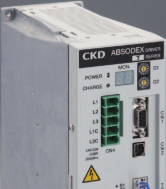
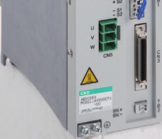
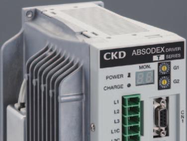
43 Direct drive actuator ABSODEX TS/TH type driver Interface specifications: Parallel I/O (NPN specifications) Parallel I/O (PNP specifications) CC-Link PROFIBUS-DP DeviceNet 29 Features zpower supply separated into main power supply and control power supply zwiring method changed from terminal block to connector zcompact and light (resin body) z7 segment LED 2-digit display zadditional encoder output (parallel I/O only) zserial communication option (built into circuit board) zadditional monitoring feature for positioning and alarms (U2, U3, and U4 options only) Common specifications Descriptions Power voltage Main power supply Breaker capacity TS type driver TS type driver AX9000TS Model TS type driver AX9000TH 3-phase, 1-phase 200 VAC ± 10% to 230 VAC ± 10% (Note 1) 100 VAC ± 10% to 115 VAC ± 10% (J1 option) (Note 2) (Note 3) Control 200 VAC ± 10% to 230 VAC ± 10% power supply 100 VAC ± 10% to 115 VAC ± 10% (J1 option) (Note 2) (Note 3) Power frequency 50/60 Hz Rated input current 200 VAC: 1.8 A 100 VAC: 2.4 A 200 VAC: 5.0 A Rated output current 1.9 A 5.0 A Structure Integrated driver and controller (open type) Operating ambient temperature 0 to 50 C Operating ambient humidity 20 to 90% RH (with no dew condensation) Storage ambient temperature -20 to 65 C Storage ambient humidity 20 to 90% RH (with no dew condensation) Atmosphere No corrosive gases or powder dust Noise resistance 1000 V (P-P), pulse width 1 μs, rising edge 1 ns, impulse noise test, induction noise (capacitive coupling) Vibration resistance 4.9 m/s 2 Weight Approx. 1.6 kg Approx. 2.1 kg Degree of protection IP2X (excluding CN4, CN5) Note 1) For models whose max. torque is 75 N m or more, if you are using 1-AC 200 VAC, the calculation of the torque limit is different from the norm. Contact CKD to determine whether the driver can be used. Note 2) If you connect 200 VAC to 230 VAC to a driver with 100 VAC to 115 VAC power supply voltage specification (-J1 option), the driver's internal circuitry will be damaged. Note 3) You cannot select "-J1" for models whose max. torque is 75 N m or more. Note 4) If the main power supply is turned off while the actuator is rotating, the rotation may continue due to momentum. Note 5) After the main power is turned off, the motor may drive due to the voltage remaining in the driver. How to order y200 to 230 VAC AX9000TS AX9000TH U0 U0 y100 to 115 VAC AX9000TS J1 U0 Performance specifications Descriptions Control shafts Angle setting unit Min. angle setting unit Speed setting unit Descriptions 1 shaft, pulses/1 rotation (degrees), pulses, index numbers 0.001, 1 pulse sec. rpm Speed setting range 0.01 to 100 s; 0.01 to 300 rpm (Note 1) Equal divisions 1 to 255 Max. command value 7-digit number input ± Timer Interface specification U0: Parallel I/O (NPN) U1: Parallel I/O (PNP) U2: CC-Link U3: PROFIBUS-DP U4: DeviceNet 0.01 s to s Program language NC language Programming method Data can be set with an interactive terminal or personal computer, etc., using the RS-232C port. Operation Mode Auto, MDI, job, single block, servo OFF, pulse string input Coordinates Absolute, incremental <5 types> Acceleration curve Modified sine (MS), modified constant velocity (MC, MC2), modified trapezoidal (MT), and trapecloid (TR) Status display LED power display Operating indication 7-segments LED display (2 digits) Communication interface RS-232 compatible I/O signals Refer to the relevant interface specifications page. Program size Approx characters (256 lines) Electronic thermal Actuator overheat protection Note 1) Max. rotation speed varies depending on the actuator to be connected. Actuator Model Driver Model Inrush current (A) Breaker capacity 1-phase 100 V 1-phase, 3-phase 200 V Rated current (A) AX2006T AX1022T, AX2012T, AX2018T 16 (Note 1) AX4009T, AX4022T AX9000TS 56 (Note 1) 10 AX1045T, AX4045T AX1075T, AX4075T - Note 1) The inrush current values are typical values for 115 and 230 VAC. TH type driver Actuator Model Driver Model Inrush current (A) Breaker capacity 3-phase 200 V Rated current (A) AX1150T, AX4150T AX1210T, AX4300T AX4500T AX410WT AX9000TH 56 (Note 1) 20 Note 1) The inrush current value is a typical value for AC230 V.
44 Parallel I/O (NPN specifications) CN3 Input signal Pin no. Signal Logic Decision 1 to 2 External power supply input +24 V ± 10% 3 to 4 External power supply input GND 5 Program number selection input (bit 0) Level 6 Program number selection input (bit 1) Level 7 Program number selection input (bit 2) Level 8 Program number selection input (bit 3) Level 9 10 I/O circuit specifications Descriptions Program number selection input 2nd digit/ program number selection input (bit 4) Program number selection input 1st digit/ program number selection input (bit 5) 1 circuit current (ma) Max. points (circuit) Max. current (ma) Input circuit Output circuit Brake output (BK+, BK-) Edge Level Edge Level 11 Reset input Edge 12 Origin return instruction input Edge 13 Start input Edge 14 Servo ON input/ program stop input Level Edge 15 Ready return/continuous rotation stop input Edge 16 Answer input/position deviation counter reset input Edge 17 Emergency stop input Negative Level 18 Brake release Input Level CN3 pulse string input signal Pin no. 19 PULSE/UP/A phase 20 -PULSE/-UP/-A phase 21 DIR/DOWN/B phase 22 -DIR/-DOWN/-B phase Signal Max. current consumption (ma) 1106 * The max. number of simultaneous output points for the output circuits is 14 out of 18. CN3 output signal TS/TH type driver Pin no. Signal Logic 33 M code output (bit 0) 34 M code output (bit 1) 35 M code output (bit 2) 36 M code output (bit 3) 37 M code output (bit 4) 38 M code output (bit 5) 39 M code output (bit 6) 40 M code output (bit 7) 41 In-position output 42 Positioning completion output 43 Start input waiting output 44 Alarm output 1 Negative 45 Alarm output 2 Negative 46 Intermediate index output 1/ origin output 47 Intermediate index output 2/servo state output 48 Ready output 49 Segment position strobe output 50 M code strobe output CN3 encoder output signal (incremental) Pin no. Signal 23 A phase (line driver output) 24 -A phase (line driver output) 25 B phase (line driver output) 26 -B phase (line driver output) 27 Z phase (line driver output) 28 -Z phase (line driver output) NPN specification AX9000TS AX9000TH Driver CN3 I/O circuit specifications Input circuit 1, 2 pin + 24 V ± 10% Pull string input circuit 240 Ω 510 Ω 19, 21 pin 5 to 18 pin Rated voltage 24 V ± 10% Rated current 4 ma (for 24 VDC) Output circuit 1, 2 pin + 24 V ± 10% Load 33 to 50 pin 20, 22 pin Max. input frequency Rated voltage 5 V ± 10% Line driver 1 Mpps Open collector 250 Kpps Encoder output circuit 23, 25, 27 pin 24, 26, 28 pin 3, 4 pin Rated voltage 24 V ± 10% Rated current 50 ma (max) Output type: line driver Line driver to use: DS26C31 Read the precautions on Intro 9 to 14 before use. * Custom order models will not support CE, UL/cUL, or RoHS. 30
45 TS/TH type driver Parallel I/O (PNP specifications) CN3 Input signal Pin no. Signal Logic Decision 1 to 2 External power supply input GND (Note 1) 3 to 4 External power supply input +24 V ± 10% (Note 1) 5 Program number selection input (bit 0) Level 6 Program number selection input (bit 1) Level 7 Program number selection input (bit 2) Level 8 Program number selection input (bit 3) Level 9 10 I/O circuit specifications Descriptions Program number selection input 2nd digit/ program number selection input (bit 4) Program number selection input 1st digit/ program number selection input (bit 5) 1 circuit current (ma) Max. points (circuit) Max. current (ma) Input circuit Output circuit Brake output (BK+, BK-) Edge Level Edge Level 11 Reset input Edge 12 Origin return instruction input Edge 13 Start input Edge 14 Servo ON input/ program stop input Level Edge 15 Ready return/continuous rotation stop input Edge 16 Answer input/position deviation counter reset input Edge 17 Emergency stop input Negative Level 18 Brake release Input Level Note 1) The wiring is different from the PNP specifications of the AX9000GS/ AX9000GH. CN3 pulse string input signal Pin no. 19 PULSE/UP/A phase 20 -PULSE/-UP/-A phase 21 DIR/DOWN/B phase 22 -DIR/-DOWN/-B phase Signal Max. current consumption (ma) 1106 * The max. number of simultaneous output points for the output circuits is 14 out of 18. CN3 output signal Pin no. Signal Logic 33 M code output (bit 0) 34 M code output (bit 1) 35 M code output (bit 2) 36 M code output (bit 3) 37 M code output (bit 4) 38 M code output (bit 5) 39 M code output (bit 6) 40 M code output (bit 7) 41 In-position output 42 Positioning completion output 43 Start input waiting output 44 Alarm output 1 Negative 45 Alarm output 2 Negative 46 Intermediate index output 1/ origin output 47 Intermediate index output 2/servo state output 48 Ready output 49 Segment position strobe output 50 M code strobe output CN3 encoder output signal (incremental) Pin no. Signal 23 A phase (line driver output) 24 -A phase (line driver output) 25 B phase (line driver output) 26 -B phase (line driver output) 27 Z phase (line driver output) 28 -Z phase (line driver output) CN3 I/O circuit specifications Input circuit 5 to 18 pin +24 V ± 10% Pull string input circuit 240 Ω 510 Ω 19, 21 pin 1, 2 pin Rated voltage 24 V ± 10% Rated current 4 ma (for 24 VDC) Output circuit 3, 4 pin +24 V ± 10% 33 to 50 pin Load 1, 2 pin Rated voltage 24 V ± 10% Rated current 50 ma (max) 20, 22 pin Max. input frequency Rated voltage 5 V ± 10% Line driver 1 Mpps Open collector 250 Kpps Encoder output circuit 23, 25, 27 pin 24, 26, 28 pin Output type: line driver Line driver to use: DS26C31 Recommended line receiver: DS26C32 or equivalent 31 * Custom order models will not support CE, UL/cUL, or RoHS.
46 CC-Link specification Communication specifications Item Specifications Power supply Supplies DC5 V from the servo amp CC-Link version Ver.1.10 Occupied stations 2 stations (remote device station) (station type) Remote input points 48 points Remote output points 48 points Remote register I/O Input 8 words, output 8 words Communication speed Coupling cable 10M, 5M, 2.5M, 625k, 156kbps (selection by parameter) CC-Link Ver.1.10-compatible cable (shielded 3-core cable) Transmission format HDLC compliant Remote station No. 1 to 63 (set by parameter) Remote device stations (2 stations) Connections occupy 32 units (max). Current position within 1 rotation (degrees, pulses), amount of position Monitor function deviation, program number, electronic thermal, rotation speed, alarm I/O signals PLC -> AX (Input) Device No. Signal Logic Decision RYn0 Program number selection input (bit 0) Level RYn1 Program number selection input (bit 1) Level RYn2 Program number selection input (bit 2) Level RYn3 Program number selection input (bit 3) Level RYn4 Program number selection input 2nd digit/ Edge program number selection input (bit 4) level RYn5 Program number selection input 1st digit/ Edge program number selection input (bit 5) level RYn6 Reset input Edge RYn7 Origin return instruction input Edge RYn8 Start input Edge RYn9 RYnA RYnB Servo ON input/ program stop input Ready return input/ continuous rotation stop input Answer input/ position deviation counter reset input TS/TH type driver Level edge Edge Edge RYnC Emergency stop input Negative Level RYnD Brake release Input Level RYnE RYnF RY (n + 1) 0 to RY (n + 1) F Not available Not available Not available RY (n + 2) 0 Monitor output execution request Edge RY (n + 2) 1 Instruction code execution request Edge RY (n + 2) 2 to Not available RY (n + 2) F * n is a value that is determined by the station No. setting. CC-Link specification AX (Output) -> PLC Device Signal No. Logic RXn0 M code output (bit 0) RXn1 M code output (bit 1) RXn2 M code output (bit 2) RXn3 M code output (bit 3) RXn4 M code output (bit 4) RXn5 M code output (bit 5) RXn6 M code output (bit 6) RXn7 M code output (bit 7) RXn8 In-position output RXn9 RXnA Positioning completion output Start input waiting output RXnB Alarm output 1 Negative RXnC Alarm output 2 Negative RXnD Intermediate index output 1/ origin output RXnE Intermediate index output 2/ Servo state output RXnF Ready output RX (n + 1) 0 Segment position strobe output RX (n + 1) 1 M code strobe output RX (n + 1) 2 to Not available RX (n + 1) F RX (n + 2) 0 Monitoring Instruction code RX (n + 2) 1 execution complete RX (n + 2) 2 to Not available RX (n + 2) F AX9000TS AX9000TH Driver TB3 input circuit specifications (emergency stop) EMG+ +24V 24 VDC external power (not included) * EMG- * External power supply can be used with the polarity reversed. Rated voltage 24 V ± 10%, rated current 5 ma or less Safety precautions Provide adequate spacing between communication cables and power lines (motor cables, power cables, etc.). If communication cables and power lines are brought close together or bundled, communication will become unstable, and communication errors and retransmission may occur due to noise. For details on laying communication cables, refer to the CC-Link laying manual and other related information. 32
47 TS/TH type driver DeviceNet specifications Communication specifications Item Communication power supply Communication power supply current consumption Communication protocol Occupied nodes Communication speed Coupling cable Node address Connections Monitor function 11 to 25 VDC 50 ma or less Specifications DeviceNet compliant: Remote I/O Input 8 bytes, output 8 bytes 500, 250, 125 kbps (selected by parameter) DeviceNet (shielded 5-core cable, 2 signal lines, 2 power lines, 1 shield) 0 to 63 (set by parameter) 64 units max. (including the master) Current position within 1 rotation (degrees, pulses), amount of position deviation, program number, electronic thermal, rotation speed, alarm I/O signals PLC -> AX (Input) Byte No Signal Logic Decision Program number selection input (bit 0) Level Program number selection input (bit 1) Level Program number selection input (bit 2) Level Program number selection input (bit 3) Level Program number selection input (bit 4)/ Level program number selection input 2nd digit edge Program number selection input 1st digit/ Level program number selection input (bit 5) edge 0.6 Reset input Edge 0.7 Origin return instruction input Edge 1.0 Start input Edge Servo ON input/ program stop input Ready return input/ continuous rotation stop input Answer input/ position deviation counter reset input Level edge Edge Edge 1.4 Emergency stop input Negative Level 1.5 Brake release Input Level 1.6 Not available 1.7 Not available 2.0 to 2.5 Not available 2.6 Monitor output execution request Level 2.7 Instruction code execution request Edge AX (Output) -> PLC Byte Signal No. Logic 0.0 M code output (bit 0) 0.1 M code output (bit 1) 0.2 M code output (bit 2) 0.3 M code output (bit 3) 0.4 M code output (bit 4) 0.5 M code output (bit 5) 0.6 M code output (bit 6) 0.7 M code output (bit 7) 1.0 In-position output Positioning completion output Start input waiting output 1.3 Alarm output 1 Negative 1.4 Alarm output 2 Negative Intermediate index output 1/ origin output Intermediate index output 2/ Servo state output 1.7 Ready output 2.0 Segment position strobe output 2.1 M code strobe output 2.2 to 2.5 Not available 2.6 Monitoring 2.7 Instruction code execution complete TB3 input circuit specifications (emergency stop) EMG+ +24V 24 VDC external power (not included) * EMG- * External power supply can be used with the polarity reversed. Rated voltage 24 V ± 10%, rated current 5 ma or less 33 Safety precautions Provide adequate spacing between communication cables and power lines (motor cables, power cables, etc.). If communication cables and power lines are brought close together or bundled, communication will become unstable, and communication errors and retransmission may occur due to noise. For details on laying communication cables, refer to the DeviceNet laying manual and other related information.
48 PROFIBUS-DP specifications Communication specifications Item Communication protocol I/O data Communication speed Coupling cable Node address Connections Monitor function Specifications PROFIBUS DP-V0 compliant Input 8 bytes, output 8 bytes 12 M, 6 M, 3 M, 1.5 M, 500 k, k, k, k, 19.2 k, 9.6 kbps (auto baud rate function) PROFIBUS cable (shielded 2-core twist pair cable) 0 to 125 (set by parameter) Without repeaters: 32 stations max. per segment With repeaters: 126 stations max. in total Current position within 1 rotation (degrees, pulses), amount of position deviation, program number, electronic thermal, rotation speed, alarm I/O signals PLC -> AX (Input) Byte No Signal Logic Decision Program number selection input (bit 0) Level Program number selection input (bit 1) Level Program number selection input (bit 2) Level Program number selection input (bit 3) Level Program number selection input (bit 4) Level /program number selection input 2nd digit edge Program number selection input 1st digit Level /program number selection input (bit 5) edge 0.6 Reset input Edge 0.7 Origin return instruction input Edge 1.0 Start input Edge 1.1 Servo ON input/ Level program stop input edge 1.2 Ready return input/ continuous rotation stop input Edge 1.3 Answer input/ position deviation counter reset input Edge 1.4 Emergency stop input Negative Level 1.5 Brake release Input Level 1.6 Not available 1.7 Not available 2.0 to 2.5 Not available 2.6 Monitor output execution request Level 2.7 Instruction code execution request Edge TS/TH type driver PROFIBUS-DP specifications AX (Output) -> PLC Byte Signal No. Logic 0.0 M code output (bit 0) 0.1 M code output (bit 1) 0.2 M code output (bit 2) 0.3 M code output (bit 3) 0.4 M code output (bit 4) 0.5 M code output (bit 5) 0.6 M code output (bit 6) 0.7 M code output (bit 7) 1.0 In-position output Positioning completion output Start input waiting output 1.3 Alarm output 1 Negative 1.4 Alarm output 2 Negative Intermediate index output 1/ origin output Intermediate index output 2/ Servo state output 1.7 Ready output 2.0 Segment position strobe output 2.1 M code strobe output 2.2 to 2.5 Not available 2.6 Monitoring 2.7 Instruction code execution complete AX9000TS AX9000TH Driver TB3 input circuit specifications (emergency stop) EMG+ +24V 24 VDC external power (not included) * EMG- * External power supply can be used with the polarity reversed. Rated voltage 24 V ± 10%, rated current 5 ma or less Safety precautions For details on laying communication cables, refer to "Installation Guideline for PROFIBUS DP/FMS" issued by the PROFIBUS Organization, the PROFIBUS wiring guide, etc. 34
49 TS/TH type driver Dimensions zts type driver 3-M4 (thread hole) ±0.5 (Mounting pitch) (100) 75 (5) 210±0.5 (Mounting pitch) Driver outline 220 Installation hole machining drawing (Note 1) zth type driver 6 3-M4 (thread hole) ±0.5 (Mounting pitch) Regenerative resistance 160 (100) 95 (5) 210±0.5 (Mounting pitch) Driver outline 220 Installation hole machining drawing (Note 1) Driver accessories Model no. AX9000TS-U0 AX9000TS-U1 Specifications Parallel I/O (NPN) Parallel I/O (PNP) Power supply connector (CN4) PC4/5-ST-7.62 PHOENIX CONTACT PC4/5-ST-7.62 PHOENIX CONTACT AX9000TS-U2 CC-Link specification PC4/5-ST-7.62 PHOENIX CONTACT AX9000TS-U3 PROFIBUS-DP specifications PC4/5-ST-7.62 PHOENIX CONTACT AX9000TS-U4 DeviceNet specifications PC4/5-ST-7.62 PHOENIX CONTACT To order additional parts, see the table for how to order. Motor cable connector (CN5) PC4/3-ST-7.62 PHOENIX CONTACT PC4/3-ST-7.62 PHOENIX CONTACT PC4/3-ST-7.62 PHOENIX CONTACT PC4/3-ST-7.62 PHOENIX CONTACT PC4/3-ST-7.62 PHOENIX CONTACT CN3 connector PE (plug) A0-008 (shell) Sumitomo 3M PE (plug) A0-008 (shell) Sumitomo 3M BLZ5.08/FAU Weidmüeller Not included MSTB2.5/5-STF-5.08AUM PHOENIX CONTACT 35
50 Installation dimensions zts type driver TS/TH type driver Installation dimensions - The Absodex driver is not dustproof or waterproof. Protect the driver so that dust, water, oil, etc. do not enter the driver. - If you are installing the Absodex driver in the control box, make sure that the temperature inside the box does not exceed 50 C, and install the driver as shown in the following diagram to secure space around it. 50 or over or over 50 or over 220 AX9000TS Note 1 (100) 50 or over AX9000TH zth type driver Driver 50 or over or over 50 or over Note 1 (100) 50 or over 220 Note 1) Determine a dimension that is sufficient for the cable that you are using. 36
51 TS/TH type driver Panel description zparallel I/O (NPN, PNP specifications) yfor 200 VAC Control power supply LED Main power supply LED Main power supply Control power supply Actuator output terminal GND terminal 2-M4 Operating indication 7 segment LED (2 digit) Gain 1 dip switch (Convergence time) Gain 2 dip switch (Load) CN1: RS-232C connector CN2: Connector for resolver cable TB1: Terminal for safety CN3: I/O connector TB2: Brake terminal yfor 100 VAC Control power supply LED Main power supply LED Main power supply Control power supply Actuator output terminal GND terminal 2-M4 Operating indication 7 segment LED (2 digit) Gain 1 dip switch (Convergence time) Gain 2 dip switch (Load) CN1: RS-232C connector CN2: Connector for resolver cable TB1: Terminal for safety CN3: I/O connector TB2: Brake terminal zcc-link specification Control power supply LED Main power supply LED Main power supply Control power supply Actuator output terminal GND terminal 2-M4 Operating indication 7 segment LED (2 digit) Gain 1 dip switch (Convergence time) Gain 2 dip switch (Load) CN1 RS-232C connector CN2 resolver cable connector Terminal for TB1 safety Transmission monitor LED CN3 CC-Link connector Terminal for TB3 emergency stop TB2 terminal Control power supply LED Main power supply LED Main power supply Control power supply Actuator output terminal GND terminal 2-M4 zprofibus-dp specifications Operating indication 7 segment LED (2 digit) Gain 1 dip switch (Convergence time) Gain 2 dip switch (Load) CN1: RS-232C connector (2-M2.6) CN2: Connector for resolver cable TB1: Terminal for safety Transmission monitor LED CN3: Connector for PROFIBUS-DP (2-#4-40UNC) TB3: Terminal for emergency stop TB2: Brake terminal zdevicenet specifications Control power supply LED Operating indication 7 segment LED (2 digit) Main power supply LED Main power supply Control power supply Gain 1 dip switch (Convergence time) Gain 2 dip switch (Load) CN1: RS-232C connector Actuator output terminal Name plate CN2: Connector for resolver cable TB1: Terminal for safety Transmission monitor LED GND terminal 2-M4 CN3: DeviceNet connector Terminal for TB3 emergency stop TB2: Brake terminal 37
52 AX Series Cable specifications Cable specifications Cable dimensions zax1000t Min. cable bending radius ø21 (Maximum diameter) ø45 (Maximum diameter) L (cable length) UNResolver cable Motor cable (43) (100) (12) (18.5) Resolver cable Motor cable 60 mm 110 mm zax2000t, AX4000T (14) (15) (16) (22) L (cable length) Resolver cable Motor cable (43) (100) (12) (18.5) Resolver cable Motor cable 60 mm 110 mm Safety precautions zwhen connecting the motor cable and driver, check that the cable's mark tubes and the driver's indication s are correct. zwhen the cable needs to be bent repeatedly, fix the cable sheath near the actuator connector. zthe cables for the AX4009T and AX2000T Series are not movable cables. Be sure to fix the cables at the connectors so that they do not move. Do not lift up the body by the cable or apply excessive force to the cable as the cable may break. zwhen connecting the cable, insert the connector securely to the back. Tighten the connector's set screws and fixing screws. zdo not modify the cable by cutting or extending it. Failure to observe this could result in faults or malfunctions. zfor cable length L, refer to the cable lengths in "How to order". Cable 38
 No dedicated power supply required. Power is supplied from the Absodex.")
53 Direct drive actuator ABSODEX (Interactive Terminal) AX0180 zfor TS type and TH type drivers Features (1) Programming is easy. Equal index programs are created easily by answering questions interactively with the dialog terminal. (2) No dedicated power supply required. Power is supplied from the Absodex. (3) Backup is possible. Program parameters can be saved. Programs can be copied. (4) Can be used with conventional models. This terminal can be used with S, GS, H, GH, and WGH type drivers, in the same manner as the conventional interactive terminal (AX0170H). Specifications Descriptions AX0180 Operation mode Edit, view, parameter, operation, and copy Program size Equal divisions, or 2000 NC program characters (1 program) Program no. Equal division programs: Program No. 0 to 999 Display 16 characters 2 lines (LCD) Input keys 17 keys (Stop key: 1, control keys: 5, numeric keys: 11) Backup Super capacitor (approx. 3 hours) Power supply Supplied from the Absodex Cable length 2 m Operating ambient temperature 0 to 50 C Operating ambient humidity 20 to 90% (with no dew condensation) Storage ambient temperature -20 to 80 C Storage ambient humidity 20 to 90% (with no dew condensation) Atmosphere No corrosive gases or powder dust Weight Terminal only approx. 140 g * The English version displays English messages. The operation panel keys are the same as those of the Japanese version. Dimensions zdialog Terminal How to order Model Model no. of options AX0180 E 140 Model no. Symbol Descriptions Blank Standard (Japanese version) E English version 72 Cable length 2 m 39
54 Dialog Terminal AX0180 Dialog Terminal Edit mode Program editing Equal division programs created interactively and operation programs created with NC codes are edited. Only one edited program can be saved. (Memory backup: 3 hours) After the equal division program is edited, parameters required for operation are edited. Up to 2000 letters are input for the NC program. Twelve sample programs are used for editing. Display mode I/O state and current position display The Absodex driver's input/output signal CN3's input/output status, the current motor position, and the alarm status, etc., are displayed. Operation mode Parameter mode Operation mode Parameter setting You can refer and set the parameters of the Absodex. * With the AX9000TS/AX9000TH serial communication option, you can set the station number, baud rate, etc. Push-in operation commands Start and stop programs, execute one block, reset, set numbers, input and execute MDI data, communicate in terminal mode, brake ON and OFF, servo ON and OFF, return to origin, execute a JOG operation, set offset, etc. Copy mode Batch copying the programs All programs stored in the Absodex driver are stored in another driver. Tuning mode Absodex adjustment (AX9000TS only) Adjust the gain using the Absodex auto tuning function. Interactive programming Examples of use You can easily create programs by entering settings similar to those shown below. [Program input example] New Program No. [0 to 999] Origin return position 1. Origin 2. Index Return direction 1. CW 2. CCW 3. Shortest route Return speed [1.0 to 20.0] rpm Divisions [1 to 255] Movement time [0.01 to 100] sec Rotational direction 1. CW 2. CCW Stop process 1. Start wait 2. Dwell Brake 1. Used 2. Not used Delay timer [0.01 to 99.99] sec M code 1. M code 2. Segment position Try operating the Absodex. Create an Absodex program and store it in the Absodex. Start a program stored in the Absodex. Use features of each cam curve. Check the I/O ON/OFF state. Edit mode Twelve types of sample programs are selectable, so try these during adjustment. Edit mode Programs and parameters are stored, and programs are copied. Operation mode Programs are created easily by inputting the following setting items. Parameter mode Five types of cam curves are selectable. Drives that use features of each type are realized in Push-in operation. Display mode You can view the I/O state. AX0180 Dialog Terminal 40
55 AX Series How to order Absodex related parts zrelated parts Part name Applicable model Model no. PC communication cable AX Series AX-RS232C-9P Note) Starting adjustment support tool "AX Tools" (Windows version) is provided for free. Download the latest version from our website. zmounting base Part name Applicable model Model no. Mounting base AX Series (Note 1) AX-AX -BASE- (Note 2) (Note 1) Mounting base does not support the AX4009T. (Note 2) Please contact our sales department regarding mounting base mod el numbers. znoise filter Part name Applicable model Model no. Noise filter for power supply (3-AC 10A) AX Series AX-NSF-3SUP-EF10-ER-6 Noise filter for power supply (1-AC 15A) AX Series AX-NSF-NF2015A-OD Surge protector AX Series AX-NSF-RAV-781BXZ-4 Ferrite core for motor cable AX Series AX-NSF-RC5060 (Note 1) The parts listed on this page can be purchased from CKD. (Note 2) To comply with EU Standards (CE marking) and UL standards, peripheral components such as circuit breakers and FG clamps must be provided by the customer. For details, refer to the instruction manual or the technical information (ABSODEX AX Series TS Type TH Type Technical Information). zothers Part name Applicable model Model no. Power supply connector (CN4) AX Series AX-CONNECTOR-PC45 Motor cable connector (CN5) AX Series AX-CONNECTOR-PC43 Housing (cover) (CN4: power connector) AX Series AX-COVER-KGG-PC45 Connector housing (cover) (CN5: Motor cable) AX Series AX-COVER-KGG-PC43 I/O connector (CN3: for parallel I/O) AX Series (-U0, U1) AX-CONNECTOR-MDR I/O connector (CN3: for CC-Link) AX Series (-U2) AX-CONNECTOR-BLZ5 I/O connector (CN3: for DeviceNet) AX Series (-U4) AX-CONNECTOR-MSTB Protection element for electromagnetic brake AX Series (-EB) AX-PARTS-TNR20V121K 41
56 Terminology AX Series Terminology Index precision The Absodex index precision is the difference between the target position set by an NC program and the actual stop position. The target position is an angle (seconds) from the reference station (origin return position). As shown in the diagram on the right, the index precision is calculated from the maximum and minimum values of the differences between the target positions and the actual stop positions. Measurement is expressed in terms of the width using positive and negative seconds, as shown on the right. A high precision encoder is used for the angular measurement. Example of index accuracy measurement -18" -27" -7" -10" " Reference station Repeatability Repeatability expresses the deviation in the angles of the stop positions measured repeatedly under the same conditions for the same target position. It is expressed as an angle (seconds). Depending on the precision characteristics that the machine requires, repeatability and index precision must be used separately. * Second: A unit used to express angles (degrees, minutes, and seconds). 1 degree = 60 minutes = 3600 seconds Measuring position Measured value 0 +5" -10" -27" -18" -7" Index precision ±16 Run out of output shaft The run-out accuracy of the inside-low section of the table installation surface. Run out of output shaft Surface run out of output shaft The run-out accuracy of the table installation surface. Surface run out 42
57 AX Series Use cases (1) Operation specifications 1 (index unit operation) Operation specifications z4 divisions (equally divided by 90 ) zmovement time 0.5 sec. z1 index in counterclockwise direction each time start is input from a PLC. Move 90 in 0.5 sec. Program example Main program O1; G11; G10\ 1A4; G91.1; A0\ F0\.5; N1M0\ ; A-1F0\.5; J1; M30\ ; Use program No. "1" Set the time (sec.) in the NC code F unit. Split one rotation into 4. Set the incremental dimensions. Move to the closest index station in 0.5 sec. Wait for the start signal input from the PLC. Move one index in 0.5 sec. Jump to the sequence No. 1 block. Program end (Note) When using the interactive terminal or Teaching Note, if the program No. 1 is input, 1 will be automatically set and does not need to be described. PLC operation signal example Initial process: process done only once in the beginning Process name I/O signal name PLC output PLC input Remarks (1) Program no. selection - No. selection bit 0 - No. selection bit 1 - No. selection bit 2 - No. selection bit 3 - No. setting first digit Select program No. 1 (Select the program number you will be using. Program No.1 is selected in this example.) (2) Return process - Start signal - Positioning completion signal - Start input waiting output Return complete by using positioning complete signal Indexing process: process done each time when indexing Process name I/O signal name PLC output PLC input Remarks (3) Index - Start signal - Positioning completion signal - Start input waiting output Index complete by using positioning complete signal (Note) Input the program No. selection and start signal when the start input waiting output turns ON. 43
58 Operation specifications 2 (oscillator unit operation) AX Series Use cases (2) 0 Operation specifications zmovement between -45 and 45 is repeated each time start is input from a PLC. zmovement time 0.7 sec. zapplies the brakes when stopping (Note 1) zenables emergency stop input (Note 2) Direct drive actuator ABSODEX Program example Main program O2; G10\ 5; G11; G90\ ; N1M69; A45F0\.7; M68; M0\ ; M69; A-45F0\.7; M68; M0\ ; J1; M30\ ; Use program No. "2". Set the unit of NC code A to angle ( ). Set the time (sec.) in the NC code F unit. Set the absolute dimensions. Release brake. Move to 45 in 0.7 sec.. Activate brake. Wait for the start signal input from the PLC. Release brake. Move to -45 in 0.7 sec.. Activate brake. Wait for the start signal input from the PLC. Jump to the sequence No. 1 block. Program end Note 1: Use an Absodex with brakes. When using the type with optional magnetic brakes, refer to the section "Using the magnetic brakes" (on page 13 in the introduction). Note 2: If an emergency stop is input during braking, the brakes will function even after the emergency stop is reset. When inputting the start signal without selecting the program No. again, release the brakes with the brake release signal, and then input the first start signal. Brake release input Start input Positioning completion output 100 msec and over 44
59 AX Series Selection guide (1) Selection guide Units and symbols for operation condition specifications Load moment of inertia (kg m 2 ) J Movement angle ( ) ψ Movement time (s) t 1 Cycle time (s) t 0 Load friction torque (N m) T F Work torque (N m) T W Cam curve Select from MS, MC, MT, and TR 1. Load moment of inertia Calculate the load moment of inertia, and temporarily select an actuator that handles moment of inertia. 2. Rotation speed The max. rotation speed Nmax is determined by ψ Nmax = Vm (rpm) 6 t1 where ψ ( ) is the movement angle and t 1 (s) is the movement time. V m is a constant that is determined by the cam curve. Confirm that Nmax does not exceed the actuator's specified max. rotation speed. <Precautions> The actual movement time is the result of adding the settling time to the Absodex movement instruction time. Speed 3. Load torque (a) The maximum load torque is obtained with the following formula. Tm = [Am (J + JM) ψ + TF + TW] fc + TMF 180 t1 2 (b) The effective value of the load torque is obtained with the following formula. t1 ψ Trms = [r Am (J + JM) fc] 2 + (TF fc + TW fc + TMF) 2 t0 180 t1 2 Here, use the values in the following table for Vm, Am, and r. Cam curve V m A m r MS MC MT TR J M, T MF, and f are as follows: J M : Output shaft moment of inertia (kg m 2 ) T MF : Output shaft friction torque (N m) fc : Usage factor (fc = 1.5 under normal use) Regarding the actuator selected temporarily Max. load torque < Max. output torque Effective load torque value < Continuous output torque If either of the conditions above is not met, increase the actuator size, and recalculate the load torque. Note) There is a torque limit area where the max. torque is reduced during high-speed rotation. When using the actuator in the torque limit area, use the model selection software to check whether the actuator can be used Absodex movement instruction time Actual moving time Time Settling time The settling time differs according to the working condition, but generally is between and 0.2 s. Use the Absodex movement instruction time for the movement time t 1 in model selection. In addition, use the Absodex movement instruction time for the designation of the movement time in an NC program. (Note) Frictional torque is applied to the output shaft due to the bearing or sliding surface or other friction. Friction torque is calculated with a relational formula. Tf = μ Ff Rf (N m) Ff = m g where, μ : Coefficient of friction Rolling friction Sliding friction μ = 0.03 to 0.05 μ = 0.1 to 0.3 Ff : Force applied to rolling surface and bearings, etc. (N) Rf : Average friction radius (m) m : Mass (kg) g : Gravitational acceleration (m/s 2 ) (Note) The work torque expresses, with a torque value, the external load, etc., applied on the output shaft as a load. Calculate the work torque TW using the following formula. T W = F W R W (N m) F W (N) : Force required for work R W (m) : Work radius (Example) If the actuator is installed horizontally (the output shaft is horizontal), table, work, and jig, etc. are the work torque. 45
60 AX Series Selection guide (1) AX9000TS type driver 4. Regenerative power For AX9000TS and AX9000TH type drivers, use the following simplified formula to calculate the regenerative power and determine whether the drivers can be used. AX9000TS type driver does not have a built-in regenerative resistor. Therefore, check that the energy that can be charged with the capacitor (table below) does not exceed the regenerative energy value determined using the simplified formula below. E = ( ψ ) 2 (J+JM) t Vm (J) Power specifications Processable regenerative energy (J) 200 VAC VAC (-J1) 17.2 Remarks When the input voltage to the main voltage supply is 200 VAC When the input voltage to the main voltage supply is 100 VAC If this condition cannot be met, consult with CKD. AX9000TH type driver With AX9000TH type driver, the power regenerated by the consumption capacity of the regenerative resistor is limited. It is determined using the following simplified formula. W = ( ψ t1 180 Vm ) 2 (J+JM) 2 t0 (W) W 40 If this condition is not satisfied, reconsider operation and load conditions. 46
61 AX Series Selection guide (1) <Usage conditions> Table radius : R = 0.4 (m) Table weight : Wt = 79 (kg) Jig rotational radius : Re = (m) Jig weight : Wj = 10 (kg/piece) (includes the work weight) Number of jigs : N = 4 <Operating conditions> Movement angle : ψ = 90 ( ) Movement time : t 1 = 0.8 (s) Cycle time : t 0 = 4 (s) Load friction torque : T F = 0 (N m) Work torque : T W = 0 (N m) Output shaft friction torque : T MF (N m) depends on the actuator specifications Cam curve : MS (modified sine) STEP 1 Calculation of moment of inertia (a) Table Wt R J1 = = 2 2 =6.32 (kg m 2 ) (b) Jig and workpiece J2 = N Wj Re 2 = = (kg m 2 ) (c) Total sum of moment of inertia J + J1 + J2 = = (kg m 2 ) STEP 2 Max. rotation speed STEP 3 Load torque Nmax = Vm ψ 90 = 1.76 =33 (rpm) 6 t Confirm that Nmax does not exceed the Absodex's maximum rotation speed. Calculate the smallest model that can tolerate the load moment of inertia. The AX4300T allowable moment of inertia is 180 (kg m 2 ) or over, so this load is allowable. Max. load torque Tm = [Am (J + JM) ψ 180 t1 2 + TF + TW] fc + TMF = [5.53 ( ) ] = (N m) Effective load torque Trms = t1 ψ [r Am (J + JM) t0 180 t1 2 fc] 2 + (TF fc + TW fc + TMF) 2 Trms = [ ] 2 + ( ) 2 = 70.7 (N m) STEP 4 Regenerative power Vm ψ W = ( ) 2 (J+JM) t t0 = ( ) = (W) W 40 (W) STEP 5 Selection guide Determine if the selected AX4300T can be used. Total sum of load moment of inertia Max. rotation speed Max. load torque Effective load torque Regenerative power Thus, AX4300T can be used. (kg m 2 ) (rpm) (N m) (N m) (w) 47
62 AX Series Selection guide (2) When selecting a model for "MC2 curve" What is the MC2 curve? The MC2 curve has a constant velocity in movement the same as the MC (modified constant velocity) curve, but by setting an acceleration/deceleration time, the constant velocity is set freely. With the MC (general name: MCV50) curve, the constant velocity section is 50%. Note. Acceleration/deceleration time is set to one-half or less of movement time. If acceleration/deceleration time setting exceeds one-half of movement time, the cam curve is automatically changed to an MS (modified sine wave) curve. In the example, acceleration/deceleration time (ta) is set to 0.5 sec. for movement time (t 1 ): 4 sec., a speed pattern that sets the constant velocity to 75% is created. When selecting a model for "continuous rotation" What is continuous rotation? Continuous rotation has the following features. 1. Continuous rotation 2. Equal division position stop t1 : To continuously rotates at a set speed until the continuous rotation stop signal is input. : To stop at an equal division when the continuous rotation stop signal is input if used with equal division designation. In the example, the shaft accelerates at acceleration time ta to set speed N, and when a continuous rotation stop is input, stops with deceleration time td. t0 0.5(ta) 4(t1) (t0) 0.5(ta) ta td Continuous Constant velocity section (75%) MC2 Selection procedure Selection procedure With the MC2 curve, the model is selected using the following formula: Movement angle : ψ ( ) Cycle time : t 0 (s) Movement time : t 1 (s) Acceleration/deceleration time : ta (s) Load moment of inertia : J (kg m 2 ) Output shaft moment of inertia : J M (kg m 2 ) Friction torque : Tf (N m) Work torque : T w (N m) Output shaft friction torque : T MF (N m) Max. speed: Nmax (rpm) ψ Nmax = 6 (t ta) Load torque (max.): T m (N m) t1-2ta ψ 1 - t ta Tm = 5.53 (J + JM) + Tf + TW fc + TMF 720 ta 2 Load torque (min.): Trms (N m) 2 t1-2ta ψ 1-2ta t ta Trms = 3.91 (J + JM) fc + [(Tf + Tw) fc + TMF] 2 t0 720 ta 2 With continuous rotation, the model is selected using the following formula: Rotation speed : N (rpm) Cycle time : t 0 (s) Acceleration time : ta (s) Deceleration time : td (s) Load moment of inertia : J (kg m 2 ) Output shaft moment of inertia : J M (kg m 2 ) Friction torque : Tf (N m) Work torque : Tw (N m) Output shaft friction torque : T MF (N m) Max. speed: Nmax (rpm) (Note 1) Nmax = N Load torque (max.): Tm (N m) 6.82N ta Tm = 5.53 (J + JM) + Tf + Tw fc + TMF 720 ta 2 Load torque (min.): Trms (N m) 2 2ta 6.82N ta Trms = 3.91 (J + JM) fc + [(Tf + Tw) fc + TMF] 2 t0 720 ta 2 The above formula applies for the case of ta td. If ta > td, then replace ta with td, and select. Note 1) When continuous rotation is used, the max. speed is limited. Follow the actuator specifications. 48
63 AX Series Selection guide (2) Inertia moment formulas A When rotation center is own shaft 1. Circular plate (cylinder) m Center of rotation R mr I = 2 2 B When rotation center differs from own shaft 1. Any shape (if sufficiently small) Center of rotation m Re [ m : Weight of object (kg)] I = mre 2 2. Hollow circular plate(hollow cylinder) R r 2 2 m ( R + r ) I = m 2 3. Cuboid b a I = m 2 2 m ( a + b ) Circular plate (cylinder) R Re I = m 3. Hollow circular plate (hollow cylinder) R Re r m I = 2 R 2 m + Re 2 R + m r + Re 2 4. Ring r m R I = 2 2 m (4 R + 3 r ) 4 4. Cuboid a m Re I = m 2 2 a + b + 12 Re 2 5. Cylinder R l l m I = 2 2 m (3R + l ) 12 b 5. Cylinder l Re I = m 3 R l + Re 2 m 6. Hollow cylinder r R m I = m ( R + r + l /3) 4 6. Hollow cylinder R l m Re I= m R + r + l /3 2 + Re 4 For conveyor m 2 m 3 A R B m 4 m 4 m 1 m 1 m 2 m 3 m 4 R r R : Chain weight : Workpiece total weight : Jig (pallet) total weight : Sprocket A (drive) + B total weight : Drive side sprocket radius I=(m 1+ m 2+ m3 + m 4 ) R
64 Absodex selection guide specifications check sheet Table direct drive Your company name Department TEL Name FAX (Note) Contact CKD for chain drives and gear drives. Operating conditions 1. Index 2. Oscillator Movement angle Ψ ( ) or, Index numbers Movement time t1 (sec) Cycle time t0 (sec) Cycle time = Moving time + Dwelling time (Note) Index time is movement time + settling time. The settling time differs according to the working condition, but generally is between and 0.20 s. Load conditions Table Material 1. Steel 2. Aluminum Outline Dt (mm) Plate thickness ht (mm) Weight m1 (kg) ht Dt Dp Rf μ Workpiece Pallet jig Workpiece Quantity nw (pcs) Max. weight mw (kg/pcs) Installation center Dp (mm) (Fig.1) Load conditions Pallet jig Quantity Max. weight np (pcs) mw (kg/pcs) Others Mounting orientation 1. Horizontal (Fig.2) 2. Vertical (Fig. 3) (Fig.2) Installation direction: Horizontal (Fig.3) Installation direction: Vertical External work 1. No 2. Yes (Note) Eccentric load caused by gravity from vertical installation, external load caused by caulking work. Dial plate support form bottom 1. No 2. Yes Coefficient of friction μ Work radius Rf (mm) Device rigidity 1. High 2. Low (Note) (Note) When using a spline, when unit cannot be fixed directly onto the device (Fig. 4), when there is a mechanism such as a chuck on the table. Extension with table shaft 1. No 2. Yes (Fig. 5) Actuator movement 1. No 2. Yes (Note) When actuator is mounted on X-Y table or vertical mechanism, etc., and mounted actuator moves. (Note) If 2 is selected for any item, contact CKD. (Note) (Fig.4) Installation rigidity: Low (Fig. 5) Extension with shaft Attach system outline and reference drawings so that the optimal model can be selected. 50


65 Related products Absodex Compact type AX6000M series Catalog No.CC-1148A Space saving With the smallest dimensions in the industry and the concentric circle shape (the rotation axis and the fixed axis are the same), you can design space-saving compact equipment. Flexible The extensive programing features enable your desired operations. Simple operation settings are also supported including automatic creation of point specification programs. Highly reliable and maintenance free The direct drive method (no gears) provides stable operation without accuracy degradation through damage or attrition of gears during overloaded operation. Electric driven actuator ERL2/ESD2 series Free combination Common controller for all models Automatic recognition of actuator Less spare parts required Controller 63-point positioning now available Most compact model in the industry Optional selection tool Setting software "E Tools" for easy setting Easy operation with the teaching pendant The next button to be pressed is indicated by illumination. Easy even for novices Catalog No.CC-1219A Electric driven actuator motor-less type Ball screw driven type ETS series Motor size: 8 types, Lead: 7 types, Motor mounting orientation: 5 types Install your favorite motor Selectable installation specifications of the origin sensor and the limit sensor 100 to 1500 mm (50 mm pitch) strokes are selectable. Wide range of use with a maximum load capacity of 150 kg and a maximum speed of 2000 mm/s Ball screw driven type Low dust generation ECS series Based on the ETS series, this model realizes low dust generation with the fully covered structure and suction ports. Motor size: 7 types, Lead: 7 types, Motor mounting orientation: 5 types Install your favorite motor Selectable installation specifications of the origin sensor and the limit sensor 100 to 1500 mm (50 mm pitch) strokes are selectable. Wide range of use with a maximum load capacity of 150 kg and a maximum speed of 2000 mm/s Belt-driven type ETV series Belt-driven type based on the ETS series. A stroke of 100 to 3500 mm (50 mm pitch) can be selected. Long strokes and high speeds are realized with a maximum speed of 2000 mm/s. Motor size: 6 types, Motor mounting orientation: 6 types Install your favorite motor Catalog No.CC-1165A, CC-1216A, CC-1217A 51


 High precision")
66 Electric driven actuator KBZ series Catalog No.CC-1102A High tact Operation with a maximum speed of 800 mm/s Use of servo motors Servo motors are used with compact shafts. Realization of high speed, high acceleration/deceleration and a high load capacity through a servo motor Absolute specifications Adopting an absolute specification with no origin return required Compact controller Thorough downsizing has been made. Electric driven actuator ESSD/ELCR series Catalog No.CC-1002A Space saving With the built-in controller, the controller space and wiring are not necessary. Install it like a pneumatic cylinder External shape, controls, and the usage are like a pneumatic cylinder. Flexible control of operation Three control modes, speed and acceleration controls, and a positioning completion range (in-position) can be set. Easy teaching Handy direct teaching with five buttons Electric driven actuator KBB series Catalog No.CC-783A High tact Maximum of 2000 mm/s (timing belt driven) High precision Repeatability: ±0.01 mm (ball screw driven) Absolute specifications All models use long-life lithium battery (lifespan: 50,000 hours) and do not require origin returning. High-performance processing with high-speed CPU The high-speed CPU provides high performance. Abundant variations Ball screw: 7 types, Timing belt: 6 types Motor mounting position: 4 directions are provided for each axis. 52
Direct drive actuator quick response type ABSODEX
 "Instantaneous positioning" quick response direct drive actuator ABSODEX Direct drive actuator quick response type ABSODEX AX1000T, AX2000T, and AX4000T Series New product DIRECT DRIVE ACTUATOR QUICK RESPONSE
Actuator specifications
 Direct drive actuator compatible type X4000G Series Compatible with large load moment of inertia Compatible function with free driver, actuator, and cable combinations Different options including hollow
DIRECT DRIVE ACTUATORS
 Meeting the requirements of FA, compact and high torque DD actuator DIRECT DRIVE ACTUATORS ABSODEX Eco-friendly Absolute type DD actuator CB-32A 2 Eco-friendly, intelligent index units comptible with different
Space-saving installation Flexible motor mounting
 Space-saving installation Flexible motor mounting compatible!! Pulse train input compatible Automatic actuator recognition Addition of new controller compatible with pulse trains Enables current position
Free position locking flat and compact cylinder UFCD Series
 Space-saving cylinder ensures safety during work in power failures or accidents. Free position locking flat and compact cylinder UFCD Series Free position locking flat and compact cylinder UFCD Series
Advanced "Positioning" is in your hand.
 AZ Series Equipped Motorized Linear Slides Motorized Cylinders EAC Series / AZ Series Equipped Motorized Linear Slides Motorized Cylinders EAC Series / Lineup Added Battery-free Absolute Sensor Equipped
New Product. High speed transfer 0.5 sec./cycle realized. Linear type P&P unit. PPLX Series PPLX SERIES CC-N-371A 4
 High speed transfer 0.5 sec./cycle realized New Product Linear type P&P unit PPLX Series PPLX SERIES CC-N-371A 4 Lb stroke length (vertical) Reliable and high speed transfer 0.5 second/cycle Available
5-Phase Stepper Motor
 Ordering Information Application model: Standard shaft type, Hollow shaft type, Shaft type+ A 8K M 5 6 6 B Motor type Motor phase Rated current Max. Holding torque Shaft type Motor length : provides single
Mechanical power cylinder
 Attaining thrust equivalent to a hydraulic cylinder -- with air pressure alone! New product Mechanical power cylinder MCP Series Mechanical power cylinder MCP Series CC-958A 1 Realize high thrust at any
Electric Actuator/Slider Type Motor Parallel Type
 INFORMATION Electric Actuator/Slider Type Motor Parallel Type RoHS Reduced in overall length Parallel Reduced dimension Reduced in height Reduced dimension Parallel In-line In-line Size Length reduction
Balancing Unit BBS Series
 Lightly supporting heavy objects just with air Balancing Unit BBS Series Balancing Unit BBS Series CC-960A Move objects weighing up to 200 kg effortlessly! Balancing Unit BBS-A
New Products. Electric Actuator ETS Series. Motorless type. Plenty variation Installation of familiar motor is available. ELECTRIC ACTUATOR ETS SERIES
 New Products Electric Actuator ETS Series New Product ELECTRIC ACTUATOR ETS SERIES Motorless type Plenty variation Installation of familiar motor is available. CC-116A High rigidity bodyets- or more size
New Products COMPACT PILOT OPERATED SOLENOID VALVE FOR WATER. Lightweight and large flow rate, low power consumption Improved corrosion resistance!
 New Products Compact Pilot Operated Solenoid Valve for Water FWD Series New Product COMPACT PILOT OPERATED SOLENOID VALVE FOR WATER Lightweight and large flow rate, low power consumption Improved corrosion
ITVX Series. Stepless control of air pressure proportional to an electrical signal. Supply pressure: 5.0 MPa
 5.0 MPa Maximum Supply Pressure High Pressure Electro-Pneumatic Regulator X Series This product is only for blowing gas. This product does not have sufficient pressure control for other applications (driving,
Stepping Motor and Driver Package. High-Efficiency AR Series. DC Power-Supply Input. Built-in Controller Type Pulse Input Type
 Stepping Motor Driver Package High-Efficiency R Series DC Power-Supply Input Built-in Type Type The extensive R Series DC Power-Supply Input lineup that utilizes high-efficiency technology. Two types are
Servo Motors C-7. Overview. Tuning-Free NX. Tuning-Free NX Series. Servo Motors. Page. NX Series C-8 C-7
 Servo Motors C-7 Servo Motors Page C-8 C-7 C-8 Servo Motor and Driver $ $ For detailed information about regulations and standards, please see the Oriental Motor website. The tuning-free servo motor and
Environment Clean Room Specification
 Environment Clean Room Specification ISO Class 4 *1 (ISO14644-1) Built-in vacuum piping Possible to mount the main body without removing the external cover etc. Body-integrated linear guide specification
New Products. 3 Port Solenoid Valve with Spool Position Detection SNP Series
 New roducts 3 ort Solenoid Valve with Spool osition Detection SN Series New roduct Reliable detection of open and close status by spool position detecting. Two safety cut off by modular connection! Main
Vacuum pump system type
 type VS*P Vacuum component C O N T E N T S Series variation 166 20 mm width universal type (/M) 168 10.5 mm width universal type (/M) 184 31.5 mm width discrete type (VSQP) 214 11 mm pitch manifold dedicated
Hybrid Control System, Alpha Step
 B Hybrid Control System, Alpha Step Hybrid Control System B-1 Overview... B-2 Overview Hybrid Control System Battery-Free, Absolute Sensor Equipped AZ Series... B-16 Electric Linear Slides EZS Series AZ
Electric Rotary Table
 Electric Rotary Table Series LER RoHS H Step Motor (Servo/24 VDC) Low profile New Continuous Basic type [mm] rotation Model H specification LER1 42 LER3 53 LER5 68 High precision type [mm] Model H LERH1
New Products. New Products. Electric actuator ERL/ESD Series ELECTRIC ACTUATOR ERL / ESD SERIES. Light Indication!! CC-1147A 2
 New Products Electric actuator ERL/ESD Series New Products ELECTRIC ACTUATOR ERL / ESD SERIES Light Indication!! CC-1147A 2 System Configuration Prepared by customer PLC Power supply 24 VDC 3.2 A (motor
240 g. 290 g. Compact and lightweight. Electric Actuators. Series LEPY/LEPS. Miniature Rod Type/Miniature Slide Table Type
 Electric ctuators Series LEPY/LEPS Miniature Rod Type/Miniature Slide Table Type Step Motor (Servo/2 VDC) and lightweight Rod Type Series LEPY Weight 2 g LEPY6-2 RoHS Maximum pushing force: N Positioning
SERVO MOTORS BRUSHLESS SERVO MOTORS OPERATING INSTRUCTIONS 2016
 SERVO MOTORS BRUSHLESS SERVO MOTORS OPERATING INSTRUCTIONS 2016 3009/16 en Ed.02.2016 Read these Operating Instructions before performing any transportation, installation, commissioning, maintenance or
Cat. No. I526-E1-1 USER S MANUAL 3G3IV-PLKEB2 /4. Braking Resistor Units 3G3IV-PCDBR2 B/4 B. Braking Units
 Cat. No. I526-E1-1 USER S MANUAL 3G3IV-PLKEB2 /4 Braking Resistor Units 3G3IV-PCDBR2 B/4 B Braking Units Thank you for choosing an OMRON Braking Resistor Unit and Braking Unit. Proper use and handling
SG-B1 SERIES / SG-A1 SERIES
 643 Door with Solenoid Interlock / Door Ultra-slim SG-B1 SERIES / SG-A1 SERIES Related Information General terms and conditions... F-7 General precautions... P.1501 PHOTO PHOTO Conforming to Machine &
NX Series. Tuning-Free AC Servo Motor Unit
 Tuning-Free AC Servo Motor Unit NX Series An AC servo motor unit that is capable of high accuracy control with easy operation. Smooth operation can be achieved in high inertia loads or belt drive applications
Light weight clamp cylinder CAC-N32/40 Series Light weight position locking clamp cylinder UCAC-N32/40 Series
 Helping lighten welding jigs and other tools Light weight clamp cylinder CAC-N32/40 Series Light weight position locking clamp cylinder UCAC-N32/40 Series New product Light weight clamp cylinder CAC-N
240 g. 290 g. Electric Actuators Series LEPY/LEPS. Miniature Rod Type/Miniature Slide Table Type
 Electric Actuators Series / Miniature Rod Type/Miniature Slide Table Type RoHS Compact and lightweight Rod Type Series Weight 24 g 6-25 Maximum pushing force: 5 N Positioning repeatability:.5 mm Possible
Insulation method Zero-cross function Indicators Applicable output load Model number Phototriac coupler Yes Yes (See page 6) Main Circuit
 Main Circuit") SSR with Failure Detection Function Detects failures in SSRs used for heater temperature control and simultaneously outputs alarm signals. This product supports the safe design of heater control systems,
SSR with Failure Detection Function Detects failures in SSRs used for heater temperature control and simultaneously outputs alarm signals. This product supports the safe design of heater control systems,
Brake Pack SB50W. Standard AC Motors A-143. Standard AC Motors Intro duction. Brake Pack. AC Speed Control Motors Inverter.
 Standard AC SB5W Standard AC Intro duction Induction Reversible Right -Angle Gearheads SB5W AC Speed Control Inverter SB5W US ES2 FE1/FE2 Watertight, Dust-Resistant Torque Accessories Installation A-143
Stepper Motors ver ver.5
 A Stepper s Stepper s A-1 Overview... A-2 Overview and... A-15 & Stepper and RK Series A-16 RK... A-47... A-51 Stepper Series A-52 Stepper Series A-8 See Full Product Details Online www.orientalmotor.com
2-Color Display Digital Pressure Switch. NPN/PNP open collector 2 outputs added. Cut-to-zero display function added. Rated Pressure Metal Body Type
 Series ISE70/75/75H New NPN/PNP open collector 2 outputs added. Cut-to-zero display function added. For General Fluids For Air 2-Color Display (Green/Red) Selectable from four patterns ON Red Green Red
2-Color Display Digital Pressure Switch. Rated Pressure Metal Body Type (ISE75H) 2-color digital. Functions
 2-color digital. Functions") Series ISE70/75/75H NPN/PNP open collector 2 outputs added. Cut-to-zero display function added. For General Fluids For Air 2-Color Display (Green/Red) Selectable from four patterns ON Red Green Red Green
Series ISE70/75/75H NPN/PNP open collector 2 outputs added. Cut-to-zero display function added. For General Fluids For Air 2-Color Display (Green/Red) Selectable from four patterns ON Red Green Red Green
Information. Electric Slide Table/In-line Motor Type. Series LESH D. In-line motor type newly added to electric slide table! Reduced cycle time
 Information Electric Slide Table/In-line Motor Type Series ESHD In-line type newly added to electric slide table! Width dimension shortened by up to % kihabara UDX F, --, Sotokanda, Chiyoda-ku, Tokyo 0-00,
2-Color Display High-Precision Digital Pressure Switch Series ZSE40A(F)/ISE40A
/ISE40A") 2-Color Display High-Precision Digital Pressure Switch Series ZSEA(F)/ISEA New M8 connector type RoHS IP65 Applicable fluid Air, Non-corrosive gas, Non-flammable gas Can copy to up to 10 switches simultaneously.
2-Color Display High-Precision Digital Pressure Switch Series ZSEA(F)/ISEA New M8 connector type RoHS IP65 Applicable fluid Air, Non-corrosive gas, Non-flammable gas Can copy to up to 10 switches simultaneously.
Technical Documentation
 Technical Documentation Product manual Holding brake controller Document: 0198441113316 Edition: V1.00, 03.2006 Important information The drive systems described here are products for general use that
2: A, B 3: A, B, Z 4: A, A _, B, B _ 6: A, A _, B, B _, Z, Z _
 Diameter mm Shaft Type/Hollow Type/Built-In Type Incremental Rotary Encoder Features Diameter mm flange type Suitable for measuring angle, position, revolution, speed, acceleration and distance Power supply:
Linear Alignment. motion. 2 Flexible combination of XY. 4 High resolution and high responsiveness. accuracy. Optical linear encoder scale head
 SADE SADE/X SADE/S 2 2 Alignment Stage SA Linear motor drive SA DE Crossed roller bearing -table Linear Alignment Points 1Compact XY-table motion. Using a Linear Way L miniature linear motion rolling guide
Hinged Safety Door Switch
 Hinged Safety Door Switch Polymer housing, IP65, and slow-action contacts with positive opening. Two actuator types are available: Shaft Arm lever Arm lever type can be adjusted to allow a right (180 ),
2-Color Display High-Precision Digital Pressure Switch
 2-Color Display High-Precision Digital Pressure Switch Series ZSE3/ISE3 2-color digital display allows you to choose the setting according to your application requirements. 4 different display settings
No.EX -OME0016-A PRODUCT NAME. SI unit. MODEL / Series / Product Number EX140-SDN1
 No.EX -OME0016-A PRODUCT NAME SI unit MODEL / Series / Product Number EX140-SDN1 Table of Contents 1. Safety instructions 2 2. Specifications 7 2-1. General specifications 7 2-2. Electrical ant network
Linear & Rotary Actuators F-41
 & F-41 & DRS Series Equipped Page Series Equipped F-4 F-41 F-4 Series Equipped $ $ For detailed information about regulations and standards, please see the Oriental Motor website. The Series is a line
Information. Electric Slide Table/In-line Motor Type. Series LESH D. In-line motor type newly added to electric slide table!
 Information kihabara UDX F, --, Sotokanda, Chiyoda-ku, Tokyo 0-00, PN UR http://www.smcworld.com 0 SMC Corporation ll Rights Reserved Electric Slide Table/In-line Motor Type Series ESHD In-line type newly
POWER REGULATOR LD -40PSU
 JZ99D4121A AMPIFIRE AMPIFIRE TYPE D-4PSU ZJ-46A ISTRUCTI MAUA Manual number JZ99D4121 Sub number A Date of preparation ov. 2 Thoroughly read this instruction manual, and then use the unit correctly. Especially,
Series ZSE30/ISE30. High Precision, 2-color Display Digital Pressure Switch. With One-touch fittings are newly introduced. PSE
 High Precision, 2-color Display Digital Pressure Switch Series SE30/ISE30 SE ISE PSE I SE3 PS I SE 1 2 SP ISA2 IS SM PF2 IF Data With One-touch fittings are newly introduced. Straight type Elbow type 16-2-1
20 amps 220 amps, 60 Hz VDC VAC G3PA-420B-VD-2 DC amps 440 amps, 60 Hz G3PA-450B-VD-2 DC12-24
 Solid State Relays (SSRs) G3PA/G3PB Long Service Life for Circuits that Cycle Frequently D D D D D Built-in heat sink increases life and reliability Voltage turn-on at zero crossing reduces initial inrush
Stepper Motors A-15 Overview Motor & Driver Stepper Motors 5-Phase Stepper Motor and Driver 5-Phase
 Stepper s A- Overview Stepper s and -Phase Stepper and RKⅡ Series & -Phase RK -Phase -Phase Page -Phase Stepper and A-6 A- A-6 -Phase Stepper and $ $ For detailed information about regulations and standards,
Solid State Relays G3RV. Model Number Structure. Ordering Information. Model Number Legend. List of Models. SSR and Socket Combinations
 Solid State Relays G3RV Slimmest OMRON plug-in SSR with maximum width 6.2 mm Long electrical life and high speed switching Large plug-in terminals for reliable connection G3RV-D (DC load) models can manage
2NC (slow-action) Direct. Model. opening
 Direct. Model. opening") Small Safety Limit Switch CSM DS_E_3_1 Smallest Class of Safety Limit Switches in the World Note: Contact your sales representative for details on models with safety standard certification. The world's
Small Safety Limit Switch CSM DS_E_3_1 Smallest Class of Safety Limit Switches in the World Note: Contact your sales representative for details on models with safety standard certification. The world's
Filterpack FR-BFP2-(H)0.4K to (H)15K
0.4K to (H)15K") INVERTER INSTRUCTION MANUAL FR-BFP2-(H)0.4K to (H)15K 1. Product Checking... 1 2. Applicable Inverter... 1 3. Installation... 2 3.1 Inverter Installation (installation of the )...2 4. Wiring... 4 5. Main
INVERTER INSTRUCTION MANUAL FR-BFP2-(H)0.4K to (H)15K 1. Product Checking... 1 2. Applicable Inverter... 1 3. Installation... 2 3.1 Inverter Installation (installation of the )...2 4. Wiring... 4 5. Main
ECONOMISER SERIES E2T USER MANUAL
 TURBO S.R.L. Electronic Control Systems for Dust Collectors e-mail: info@turbocontrols.it web: www.turbocontrols.it TEL. ++39 (0)362 574024 FAX ++39 (0)362 574092 ECONOMISER SERIES E2T USER MANUAL 24/06/2014
Model Number Structure
 Conductive Level Controller CSM DS_E_1_1 Ideal for level control for industrial facilities and equipment. Outputs can be set to self-hold at or using self-holding circuits. Sensitivity adjustment of operating
240 g. 290 g. Compact and lightweight. Electric Actuators. LEPY/LEPS Series. Miniature Rod Type/Miniature Slide Table Type
 Electric Actuators LEPY/LEPS Series Miniature Rod Type/Miniature Slide Table Type Compact and lightweight Rod Type LEPY Series Weight 24 g LEPY6-25 3 mm 2.5 mm Slide Table Type LEPS Series Weight 29 g
Information. Electric Actuator/Rod Type. Added size 63 to the LEY series! Series LEY AC Servo Motor (400 W) Size: 63. RoHS
 Size: 63. RoHS") Information SC Corporation Akihabara UDX 1F, 4-14-1, Sotokanda, Chiyoda-ku, Tokyo 1-21, JAPAN http://www.smcworld.com 12 SC Corporation All Rights Reserved Electric Actuator/Rod Type Series EY AC Servo
Information SC Corporation Akihabara UDX 1F, 4-14-1, Sotokanda, Chiyoda-ku, Tokyo 1-21, JAPAN http://www.smcworld.com 12 SC Corporation All Rights Reserved Electric Actuator/Rod Type Series EY AC Servo
LJ1H LEJS40 AC
 Low-profile/Low center of gravity Height dimension reduced by approx. 36% (Reduced by 32 mm) 9 Electric Actuator LEJ Series Slider Type/High Rigidity 58 (Former model) LJ1H2 3 5 1 LJ1H2 LEJS4 RoHS Series
Information. Model LEYG16 LEYG25 LEYG32
 Information A rod type with guide newly added! Compatible with slide-bearing and ball-bushing bearing. Compatible with moment load and stopper (slide bearing). Speed control/positioning: ax. points Positioning
RCS3-CT8C RCS3-CTZ5C. obo c y linde r. d e. High-Speed Slider Type. High-Speed Table Type
 GB High-Speed Slider High-Speed Table www.r obo c y linde r. d e Achieving the Max. Speed of 2500 mm/s and Max. Acceleration of.2 G (Instantaneous Max. Acceleration of 4.8 G) Improved High-speed Performance
AK-G/AK-GB/AK-R/AK-RB Series
 4mm/ 6mm/ 85mm Geared type/geared+rake built-in type 6mm Rotary actuator type/ Rotary actuator+rake built-in type Features Compact design and light weight with high accuracy, speed and torque Cost-effective
Series ITV0000. Compact Electro-Pneumatic Regulator ITV N Q. IITV00 02 n. How to Order. For single unit and single unit for manifold
 Compact Electro-Pneumatic Regulator Series ITV How to Order For single unit and single unit for manifold ITV N Q Pressure range. MPa MPa.9 MPa Power supply voltage 4 VDC ±% to VDC Cable connector N S L
Innovators in Protection Technology Moulded Case Circuit Breaker Instruction Manual
 Innovators in Protection Technology Moulded Case Circuit Breaker Instruction Manual 11-M61E TABLE OF CONTENTS HANDLING & MAINTENANCE Storage 1 Transport 1 STANDARD ENVIRONMENT 1 INSTALLATION AND CONNECTION
Electric Rotary Table
 Electric Rotary Table Series RoHS Model H 1 3 5 42 Rotation angle: 36 Page 47 53 68 H 49 G Model H1 H3 H5 High precision type [mm] 62 78 Max. speed: 42 /sec (7.33 rad/sec) Max. acceleration/deceleration:
Electric Cylinder. LZB/LZC Series. It can be operated like an air cylinder. LZB Series. LZC Series LEF LEJ LEL LEM LEY LES LER LEH 25A- LEC
 Electric Cylinder LZB/LZC Series It can be operated like an air cylinder. LZB Series LZC Series Model LZB LZC Max. thrust Max. speed 196 N 0 mm/s Lead screw Slide screw: ø8, ø Lead: 2, 6, Stroke 25, 40,
Pneumatic Drive Type Drill Bit Breakage Detection Sensor. DFM3 Series. The World's First!! Pneumatic-Drive Type. Catalog / Instruction Manual US.PAT.
 Pneumatic Drive Type Drill Bit Breakage Detection Sensor DFM3 Series The World's First!! Pneumatic-Drive Type Catalog / Instruction Manual US.PAT. Pneumatic Drive Type Drill Bit Breakage Detection Sensors
Safety Limit Switch
 Safety Limit Switch D4B-@N CSM_D4B-_N_DS_E_5_1 Snap-action contact with certified direct operation certification. Maintenance, seal, and resistance to shock increased and direct mechanism added. Three-conduit
E2Q6. Rectangular Proximity Sensor. Freely Change the Sensing Direction. Ordering Information. Sensors [Refer to Dimensions on page 6] DC Models
![E2Q6. Rectangular Proximity Sensor. Freely Change the Sensing Direction. Ordering Information. Sensors [Refer to Dimensions on page 6] DC Models](/thumbs/77/76421587.jpg "E2Q6. Rectangular Proximity Sensor. Freely Change the Sensing Direction. Ordering Information. Sensors [Refer to Dimensions on page 6] DC Models") Rectangular Freely Change the Sensing Direction Change between any of five sensing directions: front or 9 up, down, left, or right. Four indicators show the operating status of the from many directions.
Rectangular Freely Change the Sensing Direction Change between any of five sensing directions: front or 9 up, down, left, or right. Four indicators show the operating status of the from many directions.
(with Class-1 AC resistive load) 3. G3PB-215B-2N-VD kW max. (25 A) G3PB-225B-3N-VD 2. G3PB-225B-2N-VD kw max. (35 A) G3PB-235B-3N-VD 2
 3. G3PB-215B-2N-VD kW max. (25 A) G3PB-225B-3N-VD 2. G3PB-225B-2N-VD kw max. (35 A) G3PB-235B-3N-VD 2") Solid-state Contactor (New Heat Sink Construction) G3PB Space and working time saved with new heat sink construction. Series now includes 480-VAC models to allow use in a greater range of applications.
Solid-state Contactor (New Heat Sink Construction) G3PB Space and working time saved with new heat sink construction. Series now includes 480-VAC models to allow use in a greater range of applications.
Direct Coupled Damper Actuator Model MY6050A1001
 Specifications/Instructions Direct Coupled Damper Actuator General direct coupled damper actuator is a motorized actuator to open/close a damper. Model MY6050A00 provides -position or floating control
Read and understand this manual for safely usage.
 TS02-0183 INSTRUCTION MANUAL FOR GUARD TYPE LEVEL SENSOR MODEL:FC Read and understand this manual for safely usage. This manual describes the product of standard specification. Read the other manual for
D4DL. Guard Lock Safety-door Switch. Ordering Information. Model Number Legend Switches D4DL- -
 Guard Lock Safety-door Switch Polymer housing, IP65, and slow-action contacts with positive opening. 2 versions Mechanical lock/solenoid release Solenoid lock/mechanical release Rotatable operating head
E-124. Electric Cylinders EAC Series. AZ/AR Equipped. Features Compact and Powerful! E-124
 E-14 Cylinders Technical reference Page H-1 Regulations & Standards Page I- AR The motor component incorporates a high-efficiency, energy-saving Series electric cylinder. In addition
Rated load current (resistive load) SRP. Min. 0.9 (max. 25 of difference between voltage phase and current phase)
 SRP. Min. 0.9 (max. 25 of difference between voltage phase and current phase)") SRPH1 Series Single Phase, Analog Input Type SSR Features Power control/ Cycle control/phase control (fixed cycle/ variable cycle) are available with 4-mA analog input Superior dielectric strength : 4,000VAC
SRPH1 Series Single Phase, Analog Input Type SSR Features Power control/ Cycle control/phase control (fixed cycle/ variable cycle) are available with 4-mA analog input Superior dielectric strength : 4,000VAC
Electric Rotary Table
 Electric Rotary Table LER Series H Low profile [mm] Model H LER1 42 LER3 53 LER5 68 High precision [mm] Model H LERH1 49 LERH3 62 LERH5 78 Continuous rotation specification RoHS Rotation angle: 36 Pages
Energy efficiency and Flow
 Energy efficiency and Flow or more Estimating figure with ø6 push-in fittings Primary pressure: 0.5MPa Secondary pressure: Release to atmospheric pressure Oil-prohibition type Suitable for oil-restricted
High-Efficiency AR Series. RK Series /0.72 /Geared. CRK Series. RBK Series. CMK Series. 2-Phase Stepping Motors A-278.
 A Stepping Motors Stepping Motors Introduction A-2 Introduction AC Power Supply Input Stepping Motor and Driver Packages A-17 DC Power Supply Input Stepping Motor and Driver Packages Stepping Motors (Motor
USER MANUAL. Blazer Vista 1000/1400/2000. Uninterruptible Power System
 USER MANUAL Blazer Vista 1000/1400/2000 Uninterruptible Power System IMPORTANT SAFETY INSTRUCTIONS SAVE THESE INSTRUCTIONS This manual contains important instructions for model Blazer Vista 1000/1400/2000
MODEL: PSN3. Final Control Elements. STROKE 6: 0 to 60 mm (0 to 2.36 )
") Final Control Elements SERVO-TOP II ELECTRONIC ACTUATOR (linear type; max. thrust 5000 N) Functions & Features Control valve actuator drive I to I positioner incorporated Lightweight, compact design High
Final Control Elements SERVO-TOP II ELECTRONIC ACTUATOR (linear type; max. thrust 5000 N) Functions & Features Control valve actuator drive I to I positioner incorporated Lightweight, compact design High
For full product information, visit Use the SpeedSpec Code or scan the QR Code for quick access to the specific web page.
 Courtesy of CMA/Flodyne/Hydradyne Motion Control Hydraulic Pneumatic Electrical Mechanical (00) 6-0 www.cmafh.com Safety Interlock Switches DSL-N Super Small Class 6-Contact uard Lock Safety-Door Switch
CLOSED LOOP STEPPING MOTOR SINGLE-AXIS ROBOTS
 TRANSERVO Series Product Lineup CLOSED LOOP STEPPING MOTOR SINGLE-AXIS ROBOTS Excellent characteristics of both stepping motor and servomotor were combined. Stepping motor single-axis robots "TRANSERVO"
Related vacuum products
 Vacuum component C O N T E N T S variation 420 Position locking valve () 422 Compact vacuum regulator () 426 Vacuum break unit () 436 Vacuum filter large volume union type (VSFB) 440 Compact vacuum filter
HS5E Miniature Interlock Switches with Solenoid
 Small interlock switch with four poles and solenoid. Ideal for applications in small spaces. Compact body. 3 40 46 mm. Four-pole internal switches. Gold-plated contacts. Spring lock and solenoid lock types
Electro-Pneumatic Regulators. Electronic Vacuum Regulators
 Electro-Pneumatic Regulator Electronic Vacuum Regulator Stepless control of air pressure proportional to an electrical signal Added Fieldbus compliant specifications to New Series Reduced wiring Series
Brushless Motors D-49. Overview. AC Input BMU. Brushless Motors. AC Input. Series BLE2. AC Input. BX Series. DC Input BLH.
 Brushless Motors D-49 Overview Brushless Motors Series Series BMU BLE2 BLH BLV D-49 D-50 Brushless Motor and Driver Series $ $ For detailed information about regulations and standards, please see the Oriental
Applicable output load (See note 2.) Photocoupler Yes Yes 40 A at 110 to 220 VAC 5 to 24 VDC G3NB-240B 5 to 24 VDC G3NB-240B-UTU 5 to 24 VDC
 Photocoupler Yes Yes 40 A at 110 to 220 VAC 5 to 24 VDC G3NB-240B 5 to 24 VDC G3NB-240B-UTU 5 to 24 VDC") Solid State Relays G3NB with 40-A output at a reasonable price. Switches 9 A without a heat sink. Zero cross function enables less noise operation. Built-in varistor effectively absorbs external surges.
Solid State Relays G3NB with 40-A output at a reasonable price. Switches 9 A without a heat sink. Zero cross function enables less noise operation. Built-in varistor effectively absorbs external surges.
Input terminals Isolation method Zero cross function Operation indicator Alarm output Applicable load (See note.) Model
 Model") Solid State Relays with Built-in Current Transformer CSM DS_E_7_ A New-concept SSR with Built-in Current Transformer. Heater Burnout and SSR Shortcircuit Failure Detection. Built-in Current Transformer
Solid State Relays with Built-in Current Transformer CSM DS_E_7_ A New-concept SSR with Built-in Current Transformer. Heater Burnout and SSR Shortcircuit Failure Detection. Built-in Current Transformer
Type. Page 518. A support guide is designed to support workpieces with significant overhang.
 Environment Clean Room Specification ISO Class 4 *1 (ISO14644-1) Built-in vacuum piping Possible to mount the main body without removing the external cover etc. Body-integrated linear guide specification
Super-Mini Complete with Easy-to-Use Functions. Guided Cylinder. STM Series GUIDED CYLINDER STM SERIES CC-884A 1
 Super-Mini Complete with Easy-to-Use Functions Guided Cylinder GUIDED CYLINDER STM SERIES CC-884A 1 Super-Mini Complete with Super-mini Guided Cylinder (ø6, ø10) with free installation and wide variations
Presentation Soft starters 0 Altistart 48 soft start - soft stop units
 Presentation Soft starters 5 6 7 65_Ver.-EN.fm/ Presentation (continued) Soft starters Applications The Altistart 8 soft start - soft stop unit is a controller with 6 thyristors which is used for the torque-controlled
SERVO MOTORS BRUSHLESS SERVO MOTORS ATEX ZONE 2-22 OPERATING INSTRUCTIONS 2016
 SERVO MOTORS BRUSHLESS SERVO MOTORS ATEX ZONE 2-22 OPERATING INSTRUCTIONS 2016 3010/16 en Ed.10.2016 Read these Operating Instructions before performing any transportation, installation, commissioning,
Magnetic Field Resistant 2-color Indication Type Solid State Auto Switch
 PRODUCT NAME Magnetic Field Resistant 2-color Indication Type Solid State Auto Switch MODEL / Series / Product Number D-P3DW(A) * Series Contents Safety Instructions 2 Model Indication Method 8 Names and
Series ITV1000/2000/3000
 Electro-Pneumatic Regulator Series ITV// How to Order [Option] RoHS ITV S Model type type type Pressure range 5 MPa MPa.9 MPa CE compliant Nil Q CE compliant Note) Refer to pages, 5, and 6 for information
Electronic pressure switch for air
 pressure switch Sensors / pressure sensor Overview pressure is electrically detected, displayed and outputted. Features Various sort Wide variation is acailable from small sensor to display. CONTENTS Series
9.8 mm. Digital Pressure Switch. 3-step setting. RoHScompliant. Series ZSE10(F)/ISE10. Vertical mounting space reduced to approx.! Reduced in depth!
/ISE10. Vertical mounting space reduced to approx.! Reduced in depth!") Digital Pressure Switch Series ZSE1(F)/ISE1 Low profile 26.1mm 9.8 mm 13.5 mm 53.4 mm Reduced in depth! (Actual size) RoHScompliant Vertical mounting space reduced to approx.! 1 2 Position Detection Switch
Digital Pressure Switch Series ZSE1(F)/ISE1 Low profile 26.1mm 9.8 mm 13.5 mm 53.4 mm Reduced in depth! (Actual size) RoHScompliant Vertical mounting space reduced to approx.! 1 2 Position Detection Switch
Lexium integrated drives
 Description ILp for CANopen, PROFIBUS DP, RS ILE with brushless DC motor Description ILE comprise control electronics with a fieldbus interface for CANopen DS, PROFIBUS DP or RS and a brushless DC motor.
AS Series. RK Series. UMK Series ASX Series 0.36 /0.72. CRK Series. CMK Series 1.8. RBK Series. PK Series 1.
 A Stepping Motors Stepping Motors Introduction A-2 Introduction AC Input Stepping Motor and Driver Packages DC Input Stepping Motor and Driver Packages Stepping Motors (Motor Only) A-269 A-24 High Efficiency
Direct acting 3-port valve 3Q Series
 New Products Direct acting -port valve Q Series Handles compact -port valve applications across the board QE/Z Series Air operated valve drive Cylinder drive Suction transport Air blow QB Series QRA/B
RCP5 Series ABSOLUTE. obo c y linde r. d e. RoboCylinder with Standard Battery-less Absolute Encoder
 GB RoboCylinder with Standard Battery-less Absolute Encoder RCP Series ABSOLUTE www.r obo c y linde r. d e Introducing the RCP series actuator with battery-less absolute encoder, realizing the convenience
240 g. 290 g. Electric Actuators. Compact and lightweight. New. Series LEPY/LEPS. Offering 2 types of controller
 Electric Actuators Miniature Rod Type Compact and lightweight Rod Type Series LEPY Miniature Slide Table Type RoHS Maximum pushing force: N Positioning repeatability:. mm Possible to set position, speed
Features. 2-wire type available. Max. operation distance: 1.5 mm 0.06 in (Stable sensing range 0 to 1.2 mm 0.05 in)
") 817 Cylindrical Inductive Proximity Sensor SERIES Related Information General terms and conditions... F-3 Glossary of terms...p.1576~ guide... P.781~ General precautions... P.1579~ PHOTO PHOTO panasonic.net/id/pidsx/global
817 Cylindrical Inductive Proximity Sensor SERIES Related Information General terms and conditions... F-3 Glossary of terms...p.1576~ guide... P.781~ General precautions... P.1579~ PHOTO PHOTO panasonic.net/id/pidsx/global
Electric Rotary Table Series LER
 Electric Rotary Table Series RoHS Low profile type [mm] Model H 1 42 3 53 5 68 Continuous rotation tion Rotation angle: 36 Page 47 H High precision type [mm] Model H H1 49 H3 62 H5 78 H G Shock-less/High