TR22F Repair Manual (Electronics)
|
|
|
- Dorthy Owens
- 6 years ago
- Views:
Transcription

1 TR22F Repair Manual (Electronics)
2 Table of Contents Product Picture - TR22F Overlay - TR22F Component Placement - TR22F Display Board Component Placement - TR22F Lower Compartment Display Block Diagram - TR22F Cable Connections - TR22F Display Board Cable Connections - TR22F Drive Board LED Indicators - TR22F Display Board Indicator LEDs - TR22F Drive Board Electronic Specifications - TR22F Electronic Malfunction Troubleshooting Table - TR22F Troubleshooting Safety Key Malfunction - TR22F Troubleshooting No Start Up - TR22F Troubleshooting No Start Up - TR22F Troubleshooting Key Malfunction Soft Keys - TR22F Troubleshooting Key Malfunction Soft Keys TR22F Troubleshooting No Incline Operation - TR22F Troubleshooting Incline Position Malfunction - TR22F Troubleshooting HTR Malfunction - TR22F Troubleshooting Fuse Broke at Start -TR22F Troubleshooting Fuse Broke after Motor Moves -TR22F Troubleshooting Fuse Broke after Use - TR22F Troubleshooting ERR-1 Appears before Motor Moves - TR22F Troubleshooting ERR-1 Appears after Motor Moves - TR22F Troubleshooting ERR-3 - TR22F Troubleshooting ERR-7 - TR22F Troubleshooting ERR-10 - TR22F Troubleshooting ERR-14 - Motor Overheats - TR22F Troubleshooting ERR-14 - Fold Up Switch - TR22F Other Topics Basic Parameter Settings - TR22F Other Topics Error Code Chart - TR22F
3 Inspection and Measurement Optic Sensor - TR22F Inspection and Measurement Transformer - TR22F Inspection and Measurement Motor Brushes - TR22F Inspection and Measurement Motor Voltage Measurement - TR22F Inspection and Measurement Incline Voltage Measurement TR22F Inspection and Measurement VR Voltage Measurement TR22F Inspection and Measurement Incline Motor and VR Calibration - TR22F Inspection and Measurement Fold Up Switch Inspection - TR22F
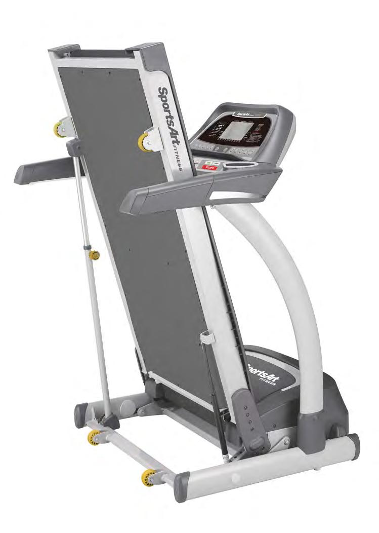
4 1-1. Product Picture TR22F 1-1-1
5 1-2. Overlay - TR22F 1-2-1


6 1-3. Component Placement - TR22F Display Board Telemetry heart rate receiver board Safety key board Display board Bridge board HTR board 1-3-1

7 1-3. Component Placement - TR22F Lower Compartment Incline VR set Optic sensor Transformer DC incline motor Motor Drive board 110V L1,L2 Close 220V L1,L2 connect to Inductor Fold up switch 1-3-2
8 1-4. Display Block Diagram - TR22F Telemetry receiver board Display board Key pad 1 Key pad 2 Safety key Key pad 3 Bridge board Sensor L Sensor R HTR board AC1 AC2 FUSE SW Filter Drive board Motor Optic sensor Transformer Thermal sensor Fold up switch Incline motor Incline VR 1-4-1
9 1-5. Cable Connections - TR22F Display Board To keys on lower part of display board To keys on upper part of display board To telemetry heart rate receiver board To safety key board To drive board To HTR receiver board To keys on upper part of display board 1-5-1
10 1-5. Cable Connections - TR22F Drive Board To VR set To display board To display board To optic sensor To incline motor To motor thermal sensor and fold up switch To transformer Fold up switch To power supply AC1, AC2 To power supply AC1, AC
11 1-6. LED Indicators - TR22F Display Board LED1 power indicator Lit indicates 5 VDC power supply


12 1-6. Indicator LEDs - TR22F Drive Board LED 7 MC indicator Flashing indicates an incoming optic sensor signal. LED 2 Lit indicates VCC power supply. LED 4 M-Temp Lit indicates motor temperature is too hot. LED5 INC-DN Lit indicates incline is operating downward. LED6 INC-UP Lit indicates incline is operating upward. LED 3 EMG Lit indicates motor circuit error. Transformer fuse 1-6-2
13 1-7. Electronic Specifications - TR22F Specification Details Notes Exterior power supply 110V / 220V Motor DC motor (with internal thermal switch) With brushes With heat protection Optic sensor Infrared optic sensor Speed range KPH: (KPH) MPH: (MPH) Power: DC motor 40V Incline Incline range: 0% -15% VR calibration: 0%= 1.20V; 15% = 3.57V Display LCD display Windows TIME / DISTANCE / CALORIE / PULSE Workout programs PROGRAM 1 PROGRAM 5 INTV1 / INTV2 Heart rate control program HRC 65% / HRC 85% Heart rate HTR / telemetry 1-7-1
14 2-1. Electronic Malfunction Troubleshooting Table - TR22F Malfunction Circumstance Inspection and test points Components to Safety key malfunction No start up No start up Telemetry heart rate malfunction Contact heart rate malfunction Put safety key in place. Display has no reaction. Safety key appears on the display. Power on indicator does not light. Power on indicator lights but the display does not light. Telemetry heart rate malfunction Contact heart rate malfunction 1. Inspect the cable connections on the lower part of the display and safety key. 2. Inspect the safety key magnet. 3. Inspect the safety key board. 1. Inspect the power cord connection. 2. Inspect all cable connections. 3. Inspect the fuse, the fuse holder, and the power switch. 4. Drive board components have an electrical short. Replace the drive board. 1. Inspect all cable connections, including connector cables. 2. Inspect whether drive board LED2 lights: a. If LED2 lights, inspect and test the transformer fuse. 3. Inspect whether LED1 on the display lights. a. If LED1 does not light, inspect the data cable from the display to the drive board. b. If LED1 does light, inspect the display program IC. Re-install the display IC. 1. Inspect the heart rate transmitter strap and its batteries. Replace batteries if they have not been replaced recently. 2. Inspect the receiver board cables. 3. Test or replace the receiver board. 4. Inspect for environmental interference, for example, from speakers and lights. 1. Inspect the HTR wire connections on the bridge board. 2. Inspect the HTR indicator light. 3. Replace the HTR board. replace Safety key board 1. Fuse, fuse holder 2. Drive board 1. Transformer 2. Drive board 3. Display board program IC 1. Heart rate transmitter 2. Heart rate receiver board 1. HTR board (Heart touch rate = contact heart rate) Notes 2-1-1
15 2-1. Electronic Malfunction Troubleshooting Table - TR22F Incline position is not correct. Key malfunction ERR 1 Incline position on display differs from actual position. Key does not operate or operates continually. Motor does not rotate, ERR 1 appears. ERR 1 Motor operates, ERR 1 appears. 1. Inspect all cable connections. 2. Inspect drive board incline VR voltage across red and green wires. Normal: 0% = 1.20 VDC, 15% = 3.57 VDC. If not, recalibrate the incline VR. 3. If VR voltage fluctuates greatly, the VR is bad. Replace the VR. If the VR voltage is correct but the height is incorrect, replace the display board. 1. Inspect the soft key connection. 2. If the <program> or <change> key is bad, replace the upper soft keys on the display. 3. If other keys malfunction, replace the lower soft keys on the display. 1. There is no power to the motor; the motor cannot operate. 2. Inspect the motor brushes. 3. Measure voltage from the drive board to the motor. If there is no voltage, replace the drive board. If there is voltage, inspect the following: a. transformer voltage. b. whether the EMG indicator lights. c. whether IGBTs have an electrical short. Replace the drive board. 4. Inspect motor brushes or the commutator. 1. The program did not detect the optic sensor signal. 2. Inspect the CLK indicator on the drive board. a. If the CLK indicator is not lit, clean or replace the optic sensor. b. If the CLK indicator lights normally, inspect the data cable from the display to the drive board. Re-install the display IC. 1. VR 2. Display board 1. Soft keys (upper) 2. Soft keys (lower) 1. Drive board 2. Motor brushes, motor 1. Optic sensor 2-1-2
16 2-1. Electronic Malfunction Troubleshooting Table - TR22F ERR 3 Display speed differs from actual speed. 1. Inspect KPH/MPH setting. 2. Inspect the optic wheel teeth. 3. Replace the optic sensor. 4. Replace the drive board. ERR 7 ERR7 appears at startup. 1. Inspect the incline VR cable connection. 2. Usually ERR7 indicates the display is stuck at either the highest or lowest position. 3. Inspect whether LED5 and LED6 light on the drive board. If lit, the display or cable malfunction may be causing a malfunction. 4. Inspect whether the drive board emits voltage to the incline motor. If not, replace the drive board. 5. Recalibrate the incline set or replace the incline set as a test. ERR14 ERR14 Display shows ERR14. The motor overheat protective function operates. Display shows ERR14, the fold up mechanism malfunctions. 1. Inspect the motor thermal switch wire and the fold up wire connection. 2. Inspect the motor thermal switch wire. Feel the motor. Is it hot? 3. If the motor is hot and the unit has been in use, turn off the unit. Let the unit rest one half hour or more. Then turn off the unit. 4. If ERR14 appears repetitively and the motor is hot, lubricate or replace the walk belt. 5. If steps above do not solve the problem, replace the motor. 1. Inspect the thermal switch and fold up switch cables. 2. Inspect whether the fold up switch has operated inappropriately. During normal operation, the fold up switch cannot touch the unit frame. 1. Optic sensor 2. Drive board 1.VR 2. Drive board 1. Drive board 2-1-3
17 2-1. Electronic Malfunction Troubleshooting Table - TR22F Main fuse is broken. Main fuse is broken. Main fuse is broken. Show total distance Telemetry heart rate malfunction Turn on unit. The fuse blows. Press the speed up key. The motor start up fuse blows. In use, the main fuse blows. No heart rate reading, please check transmitter 1. Inspect whether the power cord has an electrical short. 2. Drive board components have an electrical short. Replace the drive board. 1. Inspect the motor for abnormalities. 2. Replace the drive board. 3. Replace the motor. 1. Inspect whether the main power voltage is too low. Normal is 110V or 220V +- 10%. 2. Inspect whether the walk belt is too tight. 3. Inspect the walk belt for wear. Lubricate or replace it. 4. Inspect the condition of the fuse holder and fuse. 5. Replace the drive board. 6. Inspect motor brushes. Do not put the safety key in place. Press and hold the <CHANGE> key for three seconds. The program IC version, metric/imperial unit selection, total distance, and total time appear. 1. This error statement appears when the display IC does not receive the HRC signal. 2. Inspect whether the heart rate transmitter strap is fastened securely. 3. Replace transmitter strap batteries or the transmitter strap itself. 1. Drive board 1. Motor 2. Drive board 1. Walk belt 2. Drive belt 3. Drive board 1. Heart rate transmitter 2-1-4

18 Troubleshooting Model: TR22F Malfunction: Safety key malfunction Circumstance: Put the safety key in place. The display shows no reaction. Safety key appears. Possible cause: Safety key board malfunction Troubleshooting: 1. Inspect the safety key magnet. 2. Inspect bridge board connections. 3. Test or replace the safety key board. Safety key cable Display Board Safety key board Bridge board Bridge board Safety key board Safety key reed switch test Put safety key magnet in place Do not put the safety key magnet in place Reed switch: electrical continuity Reed switch: electrical open ON OFF 3-1-1
19 Troubleshooting Model: TR22F Malfunction: No start up. Unit does not operate. Circumstance: Turn unit power on. The power indicator does not light. Possible cause: Incoming power supply or component malfunction. Troubleshooting: 1. Inspect the power cable connection. 2. Inspect cable connections under the motor cover. 3. Inspect the main fuse, fuse holder, and power switch. 4. Inspect the drive board components for signs of burning. Or replace the drive board as a test. Inspect the main fuse, fuse holder, and power switch. Display board AC1 AC2 FUSE SW Filter Drive board Drive board 3-2-1
20 Troubleshooting Model: TR22F Malfunction: No start up. Unit does not operate. Circumstance: Turn unit power on. The power indicator does not light. Possible cause: 1. AC power supply enters the drive board, goes through the fuse, into the transformer, then into the drive board. 2.Cables are not connected properly, or the drive board is malfunctioning. Troubleshooting: 1. Inspect all cable connections. 2. Inspect whether LED2 on the drive board lights. A. If LED2 does not light, inspect the transformer fuse and measure transformer input and output voltages. 3. Inspect whether LED1 on the display board lights. A. If it does not light, inspect cable connections from the display to the drive board. B. If it does light, inspect the display IC. Re-install the display IC. LED1 power indicator Lit indicates incoming 5V power supply. Program IC LED2 VCC power AC1 LED1 Display board Transformer voltage Transformer VAC (red-red) (blue-blue) 110V (red) 220V(blue) black-black 12.5V white-white 12.5V orange-orange 29V yellow-yellow 11.5V 濾波器 AC2 Drive board Transformer FUSE LED2 Inspect the transformer fuse 3-2-2

21 Troubleshooting Model: TR22F Malfunction: Telemetry heart rate malfunction Circumstance: Telemetry heart rate malfunction Possible cause: 1. Transmitter battery voltage is too low. 2. Telemetry receiver board malfunction 3. Environmental interference, possibly from lights or speakers Troubleshooting: 1. Replace the transmitter strap or its batteries. 2. Inspect the receiver board wire connection. 3. Replace the receiver board. Telemetry heart rate receiver board Display board Heart rate receiver Telemetry transmitter (battery location) Transmitter 3-3-1


22 Troubleshooting Model: TR22F Malfunction: Key malfunction soft keys Circumstance: Press display keys. Display shows no reaction, or keys operate continually. Possible cause: 1. Bridge board soft key connections are not connected properly. 2. Soft keys are bad. Troubleshooting: 1. Inspect bridge board soft key connections. 2. Replace soft keys. Key pad 1 Display board Key pad 1 Bridge board Soft key connection Bridge board Key pad

23 Troubleshooting Model: TR22F Malfunction: Incline does not operate up or down. Circumstance: Press incline keys. Incline does not operate up or down. Possible cause: 1. Cables are not connected properly. 2. Drive board or VR malfunction. Troubleshooting: 1. Inspect all cable connections. 2. Measure whether transformer incline voltage is 29 VAC. 3. Inspect whether incline UP/DN indicators light when incline keys are pressed. If LEDs do not light, inspect cable connections and the display. If LEDs light, inspect whether the drive board emits voltage to the incline. If yes, the incline is defective. If not, replace the drive board. Incline gear box Inspect display board cable connections and the program IC. Incline VR set Measure incline VR voltage (red-green wires) 0% 1.20V 15% 3.57V Display board Test incline motor voltage: white-green 40V or -40V Transformer Drive board Incline up/down indicators VR sets Incline motor Measure voltage from the transformer to the incline orange-orange 29 VAC 3-5-1
24 Troubleshooting Model: TR22F Malfunction: Incline position malfunction Circumstance: The incline setting and actual incline position differ. Possible cause: 1. VR wear 2. Display board incline setting circuit malfunction Troubleshooting: 1. Inspect all cable connections. 2. Measure VR wires to the drive board: red-green 0% 1.20 VDC 15% 3.57 VDC If not, re-calibrate the incline set. 3. If the VR voltage fluctuates greatly, the VR set is broken. Replace the VR set. 4. If the VR voltage is correct, replace the display as a test. Inspect the display cable connections and program IC Incline VR set Display board Drive board Measure incline VR voltage (red-green wires) 0% 1.20 V 15% 3.57 V VR sets Incline motor 3-6-1


25 Troubleshooting Model: TR22F Malfunction: HTR malfunction Circumstance: Contact heart rate (HTR) value malfunction Possible cause: 1. HTR cable malfunction 2. HTR board malfunction 3. Display cable connection malfunction Troubleshooting: 1. Inspect the display cable connections. 2. Inspect bridge board HTR cable connections. 3. Inspect contact heart rate cable connections. 4. Inspect HTR board LEDs. 5. Replace the HTR board. HTR cable connection Display board HTR board HTR cable connection Bridge board Bridge board HTR board SENSOR-R SENSOR-L 3-7-1
26 Troubleshooting Model: TR22F Malfunction: The fuse has broken. Circumstance: Turn on unit. The fuse immediately blows. Possible cause: 1. Components and the frame have an abnormal electrical short. 2. Drive board component malfunction Troubleshooting: 1. Inspect the power cord. Is the cord insulation broken and creating an electrical short? 2. Replace the drive board as a test. (Drive board malfunctions are the most common source of blown fuses.) 3. Replace the filter. Fuse and power switch Drive board AC1 FUSE SW Filter Drive board AC
27 Troubleshooting Model: TR22F Malfunction: The fuse has broken. Circumstance: Press the speed key. Motor rotates. Fuse blows. Possible cause: 1. Motor has an abnormal, internal electrical short. 2. Drive board malfunction Troubleshooting: 1. Replace the drive board as a test. 2. Replace the motor as a test. 3. Replace the optic sensor as a test. Display board Sensor Motor Drive board Drive board Sensor Motor 3-8-2
28 Troubleshooting Model: TR22F Malfunction: The fuse has blown. Circumstance: After a period of use, the fuse suddenly breaks. Possible cause: 1. Fuse holder malfunction 2. Deck or belt wear 3. Drive board malfunction Troubleshooting: 1. Inspect the fuse and fuse holder installation. 2. Inspect the mechanics: A. Walk belt wear, lubrication B. Inspect walk belt tightness. Is it too loose? 3. Replace the drive board as a test. 4. Inspect the motor brushes. Drive board Display board Motor Drive board Sensor Motor 3-8-3
29 Troubleshooting Model: TR22F Malfunction: Error 1 Malfunction: Press the speed key. Speed engages. Before the motor rotates, Error 1 appears. Possible cause: 1. Motor does not rotate. Drive board or motor malfunctions. Troubleshooting: 1. Inspect all cable connections. 2. Inspect the display board IC connection. 3. Measure motor voltage from the drive board. Is there voltage across M+,M-? If not, replace the drive board. If so, A. inspect transformer output voltage. B. inspect whether the EMG LED lights. C. Do IGBTs have an electrical short? 4. Inspect motor brushes and commutator. Inspect the display cable connections and program IC. Display board Measure transformer voltage EMG indicator Transformer Drive board Sensor Motor Inspect motor brushes Measure motor M+,M- voltage 3-9-1
30 Troubleshooting Model: TR22F Malfunction: Err 1 Circumstance: Press Speed key. Motor rotates. Err1 appears. Possible cause: 1. Motor rotates optic sensor malfunctions Troubleshooting: 1. Inspect all cable connections. 2. Inspect whether CLK indicator on drive board flashes. If not, optic sensor is malfunctioning. Suggestion: A. clean the optic sensor sensor head. B. replace the optic sensor. 3. If the CLK indicator lights, inspect: A. cable connections B. main IC connections. Inspect the display cable connections and the IC connection. Display board Inspect the optic sensor CLK indicator Drive board Sensor Motor Motor Inspect motor brushes 3-9-2


31 Troubleshooting Model: TR22F Malfunction: Err 3 Circumstance: Display speed and actual speed differ. Possible cause: 1. Optic wheel teeth or optic sensor malfunction 2. Drive board malfunction Troubleshooting: 1. Inspect whether optic wheel teeth are missing. 2. Replace the optic sensor as a test. 3. Replace the drive board. Display board Inspect optic sensor and wheel. CLK indicator Drive board Sensor Motor
32 Troubleshooting Model: TR22F Malfunction: Err 7 Circumstance: Display shows ERR 7. Possible cause: 1. Drive board or VR malfunction made the incline stick at highest or lowest level. Troubleshooting: 1. Turn on unit power. Do not press any keys. Inspect drive board incline indicators LED5 and LED6. A. If LED5 or 6 lights, either the display or cable connections are at fault. B. If not lit, inspect whether the drive board emits voltage to the incline motor. If LEDs do not light, replace the drive board. If LEDs light, recalibrate the incline motor and VR Or replace the VR. Incline voltage from drive board: Display board +40V or -40V. Inspect the display cable connections and program IC connections. If the incline exceeds range, recalibrate incline set. VR wires red green: 0% = 1.20V Drive board VR sets Incline motor Incline up/dn indicators

33 Troubleshooting Model: TR22F Malfunction: ERR 10 Circumstance: The walk belt suddenly rotates quickly. Possible cause: 1. Drive board IGBT has an electrical short. The protective circuit fails. 2. The protective circuit fails, prompting the error code. This cause is unlikely. Malfunction: 1. Replace the drive board. 2. Inspect the optic sensor. IGBT Display board Drive board Optic sensor Drive board Sensor Motor
34 Troubleshooting Model: TR22F Malfunction: ERR 14 Circumstance: Display shows ERR 14, the motor overheat error. Possible cause: 1. Motor is excessively hot; overheat protective circuit operates. Troubleshooting: 1. Inspect the motor thermal switch and fold-up switch cable connections. (These two cables are connected.) 2. Inspect the motor cover. Is it hot? 3. If it is hot and the unit has been in use for a long period of time, the motor overheat protective function is operating. Turn off the unit. Let it sit without use for half an hour. 4. If ERR14 often appears, please lubricate the walk belt and deck. If the belt is worn, replace it. 5. If replacing the walk belt does not remedy the situation, the motor is suspect. Motor thermal switch cable Display board Fold up switch In normal operation, the fold up switch does not contact the frame. Drive board Fold up sensor Thermal switch Motor
35 Troubleshooting Model: TR22F Malfunction: ERR 14 Circumstance: Display shows ERR 14. The fold up switch operates. Possible cause: 1. Fold up switch operates inappropriately. Troubleshooting: 1. Inspect the motor thermal switch and fold up switch cable connections. (These two cables are connected.) 2. Inspect whether the fold up switch operated inappropriately. In normal operation, the frame should not contact the fold up switch. Motor thermal switch cable connections Display board Drive board Fold up switch In normal operation, the fold up switch does not contact the frame. Fold up switch Thermal switch
36 Other Topics Model: TR22F Item: KPH/MPH unit selection, total distance, total time, display board/drive board program versions Method: 1. Do not put the safety key in place. Press and hold the <CHANGE> key for three seconds to enter the basic parameter setting mode. 2. Program version Display shows CTL TR20H-2A (CTL indicates the display board). DRV TR20DRV-1A (DRV indicates the drive board). Press the <ENTER> key to proceed to the next step. 3. KPH/MPH setting Display shows either KPH or MPH. Press the < > / < > key to select your preferred unit of measurement. Then press the <ENTER> key to confirm your choice and proceed to the next step. 4. Total distance Display shows TOTAL DISTANCE. The DISTANCE indicator lights. The number that appears represents total distance. 5. Total time Display shows TOTAL TIME. The TIME indicator lights. The number that appears represents total time. Press the <ENTER> key to leave the basic parameter setting
37 Other Topics Model: TR22F Item: Error Code Table E-1 : Display board main program has not received the optic sensor signal. E-3 : Display setting and actual speed differ. E-7 : The display detected that the incline VR voltage is too high or too low, indicating that the incline is stuck in the wrong position. E-10 : The motor suddenly sped up. E-14 : 1. Motor temperature is excessively high. 2. The fold up indicator signal operated
38 Inspection and Measurement Inspection point: TR22F optic wheel, optic sensor Inspection method: 1. Inspect the optic wheel placement. The optic wheel should rotate in the center of the optic sensor. It should not touch the optic sensor. 2. Inspect whether optic wheel teeth have broken. 3. Pull the walk belt to allow the optic wheel to move. Inspect whether LED7 on the drive board flashes. When a tooth of the optic wheel is in the center of the optic sensor, LED7 on the drive board does not light. When a tooth of the optic wheel is not in the center of the optic sensor, LED7 on the drive board lights. 4. The optic sensor includes an infrared transmitter and a receiver. Inspect whether the optic sensor is dirty. If so, wipe it clean. LED7 optic sensor signal indicator Optic sensor Optic wheel 4-1-1
 110V (red)/220v(blue) black-black (normal power) 12.")
39 Inspection and Measurement Inspection point: TR22F transformer Inspection method: 1. Inspect whether the transformer fuse has blown. 2. Measure transformer voltage. 3. Set the multi-meter to the AC setting. Place probes as follows: Transformer cables Voltage red-red or blue-blue (input voltage) 110V (red)/220v(blue) black-black (normal power) 12.5V white-white (normal voltage) 12.5V orange-orange (incline voltage) 29V yellow-yellow (normal voltage) 11.5V Transformer connector Transformer fuse 4-2-1


40 Inspecting and Measuring Inspection point: TR22F motor brushes Inspection method: 1. Inspect motor brushes. A. Inspect brush length. If brushes are shorter than 0.7mm, replace the brushes. B. Inspect the brush surface. It should be smooth. If there are grooves, the commutator might be faulty. C. Inspect whether brush copper wires have changed color. If so, replace the brushes. Brush length should exceed 0.7 mm. This image shows brushes that are too short. Motor brushes If copper wires have changed color, connections are bad. Replace the brushes. Brush ends shown here have scratches, a sign of irregular wear. Replace brushes like these. Motor brushes 4-3-1


41 Inspection and Measurement Inspection point: TR22F motor voltage test at the drive board Inspection method: 1. Select the VDC setting on the multi-meter. Place probes on M+M- connectors on the drive board. 2. Press the SPEED< > key. The motor should operate, allowing you to measure motor voltage. Speed Drive board voltage Motor specifications Highest speed VDC 110V Lowest speed VDC 220V 4-4-1

42 Inspection and Measurement Inspection point: TR22F incline voltage measurement at the drive board Inspection method: 1. Do not press any key. Incline indicators do not light. The drive board does not emit voltage to the incline motor. The incline motor does not operate. 2. Select the VDC setting on the multi-meter and test as follows. Incline key Indicator on drive board Drive board incline voltage Incline operation INCLINE < > LED5 lights (DOWN) green-white +40 or -40V Incline operates down INCLINE < > LED6 lights (UP) green-white +40 or -40V Incline operates up Incline motor connection on drive board Incline indicators (LED5 LED6) on the drive board 4-5-1
43 Inspection and Measurement Inspection point: Measuring VR voltage on the drive board Inspection method: 1. Select the VDC setting on the multi-meter. Place probes on the VR set red-green wires. 2. If the VR voltage fluctuates widely, the VR is bad. Replace it. Incline key Drive board VR voltage Incline position 0% Red-green 1.20V At red line (calibration point) 15% Red-green 3.57V Longest position Incline VR connector at the drive board Incline red calibration line 4-6-1

44 Inspection and Measurement Inspection point: Incline motor and VR calibration Inspection method: I. Calibration goals Adjust the incline set tube to the red calibration line. Adjust the VR voltage across red and green wires to 1.20V. II. Calibration steps: Step 1. Adjust the incline tube to the red calibration line as follows: A. Remove VR set screws. Remove the VR cap. B. Rotate the VR to set voltage across red and green wires to 2.5V. C. Press the INCLINE< >/< > keys to operate the incline up or down, making the incline tube return to the red calibration line. Step 2. Adjust the VR voltage across red and green wires to 1.20V. A. Rotate the VR to set voltage across red and green wires to 1.20V. B. Use screws to secure the VR cap back into place. Step 3. When calibration is complete, test incline operation as follows. A. Press the Incline< > key. The incline should operate to 15%. Measure incline VR voltage. It should be 3.57V. B. Press the Incline< > key. The incline should operate to 0%. Measure incline VR voltage. It should be 1.20V. Incline position Incline set Incline VR Treadmill position 0% At red calibration line 1.20V Level position 15% At longest point 3.57V Highest position VR voltage adjustment Incline red calibration line 4-7-1

45 Inspection and Measurement Inspection point: Fold up switch inspection Inspection method: 1. Fold up switch and motor thermal sensor cable connections. 2. Inspect fold up cable connections. 3. Inspect the fold up switch and unit position. Drive board LED4 operates as follows: Unit Fold up switch Drive board LED 4 In normal use Not touching unit Not lit Abnormal Touches unit Lit LED4 M_TEMP indicator Lit indicates error Fold up switch should not touch unit 4-8-1
T611 Repair Manual (Electronics)
") T611 Repair Manual (Electronics) Table of Contents 1-1-1. Product Picture T611 1-2-1. Overlay T611 1-3-1. Component Placement T611 Display Board 1-3-2. Component Placement T611 Lower Compartment 1-4-1.
T611 Repair Manual (Electronics) Table of Contents 1-1-1. Product Picture T611 1-2-1. Overlay T611 1-3-1. Component Placement T611 Display Board 1-3-2. Component Placement T611 Lower Compartment 1-4-1.
T621 Repair Manual (Electronics)
") T621 Repair Manual (Electronics) Table of Contents 1-1-1. Product Picture-T621 1-2-1. Display-T621 1-3-1. Component Placement-T621 Display 1-3-2. Component Placement-T621 Drive Board Area 1-4-1. Block
T621 Repair Manual (Electronics) Table of Contents 1-1-1. Product Picture-T621 1-2-1. Display-T621 1-3-1. Component Placement-T621 Display 1-3-2. Component Placement-T621 Drive Board Area 1-4-1. Block
T631 Repair Manual (Electronics)
") T631 Repair Manual (Electronics) Table of Contents 1-1-1. Product Picture-T631 1-2-1. Display-T631 1-3-1. Component Placement-T631 Display 1-3-2. Component Placement-T631 Drive Board Area 1-4-1. Block
T631 Repair Manual (Electronics) Table of Contents 1-1-1. Product Picture-T631 1-2-1. Display-T631 1-3-1. Component Placement-T631 Display 1-3-2. Component Placement-T631 Drive Board Area 1-4-1. Block
T652 Repair Manual (Electronics)
") T652 Repair Manual (Electronics) Table of Contents 1-1-1. Product Illustration T652 1-2-1. Display T652 1-3-1. Component Placement T652 Display 1-3-2. Component Placement T652 Drive Compartment 1-4-1.
T652 Repair Manual (Electronics) Table of Contents 1-1-1. Product Illustration T652 1-2-1. Display T652 1-3-1. Component Placement T652 Display 1-3-2. Component Placement T652 Drive Compartment 1-4-1.
T630 Treadmill Repair Manual SPORTS ART INDUSTRIAL CO., LTD.
 T630 Treadmill Repair Manual SPORTS ART INDUSTRIAL CO., LTD. Table of Contents 1. Unit Components 1-1-1. T630 Product Picture 1-1-2. T630 Treadmill Components (1) Display Area 1-1-3. T630 Treadmill Components
C520U/C531U Repair Manual
 C520U/C531U Repair Manual Table of Contents 1-1-1. Display Picture C520/C531 1-2-1. Component Placement - C520U/C531U Display 1-2-2. Component Placement - C520U/C531U Lower Body 1-3-1. Block Diagram -
WARNING: ALWAYS UNPLUG THE TREADMILL FROM THE ELECTRICAL OUTLET BEFORE SERVICING THE UNIT.
 Z700-A82 / 120V Treadmill WARNING: ALWAYS UNPLUG THE TREADMILL FROM THE ELECTRICAL OUTLET BEFORE SERVICING THE UNIT. Table of Contents TABLE OF CONTENTS Table of Contents...1 Table of Figures...3 Description...4
WARNING: ALWAYS UNPLUG THE TREADMILL FROM THE ELECTRICAL OUTLET BEFORE SERVICING THE UNIT.
 Z100-A81 CE Treadmill WARNING: ALWAYS UNPLUG THE TREADMILL FROM THE ELECTRICAL OUTLET BEFORE SERVICING THE UNIT. Table of Contents TABLE OF CONTENTS Table of Contents...1 Table of Figures...3 Description...4
TROUBLESHOOTING TROUBLESHOOTING
 FOR 2007 TREADMILLS: (T9200 SIMPLE, T9500 SIMPLE, T9600 SIMPLE, T9250 SIMPLE, T9450 SIMPLE) (T9200 DELUXE, T9500 DELUXE, T9600 DELUXE, T9250 DELUXE, T9450 DELUXE) (T9200 PREMIER, T9500 PREMIER, T9600 PREMIER,
About this Troubleshooting Document
 About this Troubleshooting Document This document lists the error codes that exist within the Precor software hierarchy. Each section will include a description of the error code being displayed and the
ELECTRIC FENCE ENERGIZER SERVICE MANUAL MODEL 950 SERVICE MANUAL FOR OLLI 950 FENCE ENERGIZERS
 ELECTRIC FENCE ENERGIZER MODEL 950 SERVICE MANUAL Service Manual for OLLI 950 Page 1/16 Date 20.10.2014 Table of Contents...1 1. IMPORTANT SAFETY INSTRUCTIONS...2 2. SPECIFICATIONS...3 3. CONSTRUCTION...4
1. OVERVIEW DRAWING 2
 1 1. OVERVIEW DRAWING 2 2. IMPORTANT SAFETY INSTRUCTIONS When using an electrical appliance, basic precautions should always be followed, including the followings: Read all instructions before using the
True Fitness Service Manual. 455 Pediatric Treadmill
 True Fitness Service Manual 455 Pediatric Treadmill True fitness technology, Inc. makes no representations or warranties regarding the contents of this manual. We reserve the right to revise this document
Owner s Manual Currency Counter
 Owner s Manual 4820 Currency Counter TABLE OF CONTENTS 1. Product View 1.1. Front and Rear Views 1.2. LED Display/Control Panel 1.3. Side Control Panel 2. Operation 2.1 Operation Modes 2.2 The Right Way
Modulating Furnace Information. Warning on Meter Setting - Read First!
 Modulating Furnace Information Pressure Transducer Pressure DC Volts 0.00" 0.25 0.20" 0.63 0.25" 0.72 0.30" 0.82 0.35" 0.91 0.40" 1.00 0.45" 1.09 0.50" 1.19 0.55" 1.28 0.60" 1.38 0.65" 1.47 0.70" 1.56
Furnace Web Site FAQs. Pro Press 100 / Pro 100 / Pro 100 plus. Lift. Belt Noise
 Furnace Web Site FAQs Pro Press 100 / Pro 100 / Pro 100 plus Lift Belt Noise A Worn belt Over time the belt may become dry or worn due to heat and travel. Replace the belt Tight If the belt was recently
9.17, 9.17si Treadmill
 9.17, 917si Treadmill 9.17, 9.17si Treadmill Warning: This service manual is for use by Precor trained service providers only. If you are not a Precor Trained Servicer, you must not attempt to service
9.25, 9.25i Treadmill
 9.25, 9.25i Treadmill Warning: This service manual is for use by Precor trained service providers only. If you are not a Precor Trained Servicer, you must not attempt to service any Precor Product; Call
BIGLA30-T/BIELA14-T Event Codes Quick Reference EXPLANATION CORRECTIVE ACTION PARTS TO CARRY ON SERVICE CALL
 E13 TEMPERATURE PROBE FAILURE E16 HIGH LIMIT 1 EXCEEDED A. TEMP Probe reading out of range. B. Bad Connection. C. Problem with the temperatur e measuring circuitry including the probe. High limit temperature
Installation. Aerada 1200 Series CS Faucet S Battery-Operated Capacitive Sensing Gooseneck Faucet IMPORTANT
 Installation erada 1200 Series CS Faucet S53-325 Battery-Operated Capacitive Sensing Gooseneck Faucet Centershank with 4-inch Trim Plate (Optional: 8-inch or No Trim Plate) Table of Contents Supplies Required..................
REFRIGERATION COOLERS
 REFRIGERATION COOLERS CF Series and CFX Series Technical Specifications and Trouble Shooting USA & Canada Service Office Dometic Corporation 1120 North Main Street Elkhart, IN 46514 Service Center & Dealer
C960, C962, C964 Treadmill
 C960, C962, C964 Treadmill Warning: This service manual is for use by Precor trained service providers only. If you are not a Precor Trained Servicer, you must not attempt to service any Precor Product;
HOW - TO WIRING & LIGHTING
 HOW - TO WIRING & LIGHTING Tool And Material Checklist Test Light Service Manual Penetrating Oil Long-Nose Pliers T-Square or Right Angle Screwdriver Black Electrical Tape Fuses Fuse Puller Cloth or Paper
Symptom Possible Cause Test Procedure Repair
 Troubleshooting Guide: E2 Error/Erratic Speed Prepared by: Regina Templeton Date Prepared: 12/07/2015 E2 error on a unit with an analog speed sensor (The analog speed encoder signal indicates speed is
9.2, 9.2s, 9.20, 9.20s Treadmill
 9.2, 9.2s, 9.20, 9.20s Treadmill Warning: This service manual is for use by Precor trained service providers only. If you are not a Precor Trained Servicer, you must not attempt to service any Precor Product;
Mobile Column Lift Set
 Mobile Column Lift Set Capacity 8200kg (18000Lbs)/ Each Column Item No. 167219B Service Manual 2012. Aug. INDEX CHAPTER 1. PRE-CHECKING-------------------------------------------------------------------PAGE
Service Manual. For the SCV2832E, SCV2426, Automatic Scrubbers For: Training Troubleshooting
 Service Manual For the SCV2832E, SCV2426, SCV280000 & ES2832 Automatic Scrubbers For: Training Troubleshooting Adjustments Contents 1 Cautions ----------------------------------------------------------------------
ST Charger. Industrial Battery Charger
 ST Charger Industrial Battery Charger Installation and Operation Manual ST_13 Table of Contents Pg# 1.0 INSTALLATION 1 1.1 Receiving 1 1.2 Location 1 1.3 Line Voltage 1 1.4 A.C. Service Requirements 2
9.31, 9.33, 9.35 Treadmill
 9.31, 9.33, 9.35 Treadmill Warning: This service manual is for use by Precor trained service providers only. If you are not a Precor Trained Servicer, you must not attempt to service any Precor Product;
Setup and Programming Manual
 Microprocessor and Handy Terminal Setup and Programming Manual Versions U04 to U19 for Sliding Door Systems P/N 159000 Rev 7-2-07 The manufacturer, NABCO Entrances, Inc. suggests that this manual be given
TD80 LEVEL GAUGING & OVERFILL PREVENTION SYSTEM PRODUCT MANUAL. TPM 001 Revision 0.1
 TD80 LEVEL GAUGING & OVERFILL PREVENTION SYSTEM PRODUCT MANUAL Revision 0.1 3 TD80 and Overfill Prevention System Troubleshooting Equipment Required: 1. Automotive Test light, 6VDC to 24VDC 2. Short length
AP500 FAULT FINDING NEW INSTALLATION
 AP500 FAULT FINDING NEW INSTALLATION This Bulletin covers the AP500 model which is identified by a black plastic Electronic Module with a silver printed label. This module would normally be mounted behind
TC1000 Service Manual SALES: CUSTOMER SERVICE:
 TC1000 Service Manual SALES: 800-278-3933 CUSTOMER SERVICE: 800-745-1373 Table of Contents Section Page I. Overview 2 II. Troubleshooting Tables 3 III. Maintenance Procedures Procedure 1 Removal and Reinstallation
2015 EDITION SUBMERSIBLE MOTORS AIM MANUAL. APPLICATION INSTALLATION MAINTENANCE 60 Hz, Single-Phase and Three-Phase Motors. franklinwater.
 0 EDITION AIM MANUAL SUBMERSIBLE MORS APPLICATION INSTALLATION 60 Hz, Single-Phase and Three-Phase Motors franklinwater.com All Motors System Troubleshooting Motor Does Not Start A. No power or incorrect
MINE CHARGER INSTALLATION AND OPERATION MANUAL MODEL NUMBERS: MSP MSQ MSR MSS
 MINE CHARGER INSTALLATION AND OPERATION MANUAL MODEL NUMBERS: MSP MSQ MSR MSS Sec# Table of Contents Pg# 1 INSTALLATION 1.1 Receiving 1 1.2 Location 1 1.3 Line Voltage Adjustments 2 1.4 A.C. Service Requirements
BASIC TROUBLE SHOOTING (PERFECTPASS FOR MECHANICAL ENGINES) How PerfectPass Works
 How PerfectPass Works") BASIC TROUBLE SHOOTING (PERFECTPASS FOR MECHANICAL ENGINES) How PerfectPass Works Through the in-dash display the driver sets the desired boat speed or engine RPM depending upon which mode of operation
BASIC TROUBLE SHOOTING (PERFECTPASS FOR MECHANICAL ENGINES) How PerfectPass Works Through the in-dash display the driver sets the desired boat speed or engine RPM depending upon which mode of operation
Section Five - Troubleshooting Procedures
 Section Five - Troubleshooting Procedures Note: This section contains troubleshooting procedures specific to the C96X family of treadmills. Please refer to the troubleshooting procedures in the commercial
Troubleshooting 3Z8 038 Rev B
 Troubleshooting 3Z8 038 Rev B INSTRUCTIONS WARNING INJECTION HAZARD This form is only a quick reference for troubleshooting Graco sprayers. To reduce the risk of serious injury, including fluid injection,
Troubleshooting Guide: 355 Lights (24V)
") Troubleshooting Guide: 355 Lights (24V) Contents Description Refer To: Troubleshooting - Troubleshooting Chart Adjustments / Repair Procedures Bulb Replacing the Bulb Fuse(s) Replacing the Fuse (Ceiling)
Troubleshooting Guide: 355 Lights (24V) Contents Description Refer To: Troubleshooting - Troubleshooting Chart Adjustments / Repair Procedures Bulb Replacing the Bulb Fuse(s) Replacing the Fuse (Ceiling)
Troubleshooting Manual
 Troubleshooting Manual NOTICE: DO NOT DISCARD THIS MANUAL Models: LEGACY42-IFT PHOENIX42-IFT 1 TABLE OF CONTENTS A. Normal Operation...3 B. Wiring Diagram...4 C. Troubleshooting IntelliFire Touch...5 D.
TECHNICAL SERVICE MANUAL FOR MASTERTIG ACDC MACHINES
 TECHNICAL SERVICE MANUAL FOR MASTERTIG ACDC MACHINES TECHNICAL SERVICE MANUAL FOR MASTERTIG ACDC INTRODUCTION / GENERAL MAINTENANCE OF MASTERTIG ACDC Maintenance of the Mastertig ACDC machine would normally
LS8.0T Service Manual
 LS8.0T Service Manual 1 TABLE OF CONTENTS CHAPTER 1: SERIAL NUMBER LOCATION...3 CHAPTER 2: PREVENTATIVE MAINTENANCE 2.1 Preventative Maintenance. 4 2.2 Tension and Centering the Running Belt....6 CHAPTER
TIRE PRESSURE AND MONITORING SYSTEMS (DIAGNOSTICS)
") TIRE PRESSURE AND MONITORING SYSTEMS (DIAGNOSTICS) Basic Diagnostic Procedure 1. Basic Diagnostic Procedure A: PROCEDURE CAUTION: Remove foreign matter (dust, water, oil etc.) from the tire pressure monitoring
TIRE PRESSURE AND MONITORING SYSTEMS (DIAGNOSTICS) Basic Diagnostic Procedure 1. Basic Diagnostic Procedure A: PROCEDURE CAUTION: Remove foreign matter (dust, water, oil etc.) from the tire pressure monitoring
EASY ASSEMBLY FOLDING TREADMILL SF-T7610 USER MANUAL
 EASY ASSEMBLY FOLDING TREADMILL SF-T7610 USER MANUAL IMPORTANT! Please retain owner s manual for maintenance and adjustment instructions. Your satisfaction is very important to us, PLEASE DO NOT RETURN
ERROR CODES BIKES CROSS TRAINING
 BIKES ERROR CODES 3610, 3670, 3710, 3770, The BIKE and SEMI System stall System will not calibrate Belt worn, broken or off flywheel X Large red X displayed Replace display or send in for repair 3900,
Maintenance Information
 45530136 Edition 1 July 2008 Electric Screwdrivers EL 24V DC Series Maintenance Information Save These Instructions WARNING Always wear eye protection when operating or performing maintenance on this tool.
ACCUSENSE CHARGE SERIES ON/OFF BOARD FULLY AUTOMATIC BATTERY CHARGER
 ACCUSENSE CHARGE SERIES ON/OFF BOARD FULLY AUTOMATIC BATTERY CHARGER SPECIFICATIONS: *Photo for reference only* Part number 8890439 Mode Select: Selects Battery Type Refer to Section 6. IMPORTANT: READ
OPERATOR TROUBLESHOOTING GUIDE
 OPERATOR TROUBLESHOOTING GUIDE ABOUT THE TROUBLESHOOTING GUIDE This document is provided for the use of qualified operator installers. The installer should familiarize themselves with this guide Options
2013 Elite T4000 (TM461C) Service Manual
 Service Manual") 2013 Elite T4000 (TM461C) Service Manual 1 TABLE OF CONTENTS CHAPTER 1: SERIAL NUMBER LOCATION...3 CHAPTER 2: PREVENTATIVE MAINTENANCE 2.1 Preventative Maintenance. 4 2.2 Tension and Centering the Running
2013 Elite T4000 (TM461C) Service Manual 1 TABLE OF CONTENTS CHAPTER 1: SERIAL NUMBER LOCATION...3 CHAPTER 2: PREVENTATIVE MAINTENANCE 2.1 Preventative Maintenance. 4 2.2 Tension and Centering the Running
RF Point Level Control with Sensor Monitor
 The 681 Point Level Control utilizes DPDT relays to provide switching for peripheral devices (such as pumps) in level applications. A sensor attached to the control acts as an antenna to transmit the process
AFT mid drive kit Trouble shooting guide For 24v to 48V Kelly Controller KBS 48101L-L 100 A peak
 Date: 2016-13-1 AFT mid drive kit trouble shooting guide Rev 1.7 Page 1 of 17 AFT mid drive kit Trouble shooting guide For 24v to 48V Kelly Controller KBS 48101L-L 100 Table of Contents 1. Safety... 2
MD10. Engine Controller. Installation and User Manual for the MD10 Engine Controller. Full Version
 MD10 Engine Controller Installation and User Manual for the MD10 Engine Controller. Full Version File: MartinMD10rev1.4.doc May 16, 2002 2 READ MANUAL BEFORE INSTALLING UNIT Receipt of shipment and warranty
INSTALLATION GUIDE Chevrolet Monte Carlo Dash Panel Part Number: DP9002 Year Series:
 Made in America Lifetime Guarantee Thank you for purchasing this instrument from Intellitronix. We value our customers! INSTALLATION GUIDE Chevrolet Monte Carlo Dash Panel Part Number: DP9002 Year Series:
WARNING WARNING WARNING. English Quick start guide CAUTION CAUTION. Installation Precautions
 English Quick start guide Symbol Identification This manual uses symbols and icons to indicate safety precautions and concerns during the installation procedure. Be sure to carefully read and understand
JBI Docupunch P33 Automatic Punch
 JBI Docupunch P33 Automatic Punch Instruction Manual Provided By http://www.mybinding.com http://www.mybindingblog.com TABLE OF CONTENTS SECTION I: INSTALLATION & TESTING: 1) Uncrating, Inspection & removal
SPACE SAVING FOLDING TREADMILL SF-T7632 USER MANUAL
 SPACE SAVING FOLDING TREADMILL SF-T7632 USER MANUAL IMPORTANT: Read all instructions carefully before using this product. Retain owner s manual for future reference. For customer service, please contact:
TABLE OF CONTENTS. Understanding the Troubleshooting Instructions...2 Signal Light...2 Harness Connections...2 Inspection...2
 TRIPP Model D ELECTRICAL TABLE OF CONTENTS Understanding the Troubleshooting Instructions...2 Signal Light...2 Harness Connections...2 Inspection...2 LVDT Setup/Adjustments...2 Basic Troubleshooting...3
EB Conveyor Maintenance Guide
 EB Conveyor Maintenance Guide EN-0037 Rev A EB Conveyor Maintenance Guide www.qdraw.com Table of Contents Overview Page 3 Exploded View Of A Standard EB Conveyor Page 4 Preventative Maintenance Page 5
INSTALLATION INSTRUCTIONS
 INSTALLATION INSTRUCTIONS [1] Description: Tow Hitch Wire Harness Kit [2] Application: Nissan Rogue Note: Tow Harness application is limited to specific vehicle option packages that include tow harness
JEEVES. JEEVES Installation Manual. Installation Manual The Easiest Do-It-Yourself Dumbwaiter on the Market
 1 888-323-8755 www.nwlifts.com JEEVES Installation Manual The Easiest Do-It-Yourself Dumbwaiter on the Market This manual will cover the installation procedure step-by-step. The installation of this dumbwaiter
TROUBLESHOOTING GENERAL SOFTWARE UPLOAD. Troubleshooting 1
 TROUBLESHOOTING GENERAL FIXTURE DOES NOT RESET Blown fuse: LEDs on the printed circuit board light up to indicate the power supplies are working. Check / replace the fuses on the circuit board if one or
Sears Canada Service Manual
 Sears Canada Service Manual Treadmills Models 30750, 30727 Table of Contents >> Table of Contents Section One Section Two Safety Instructions 3 Horizon Fitness 5-Step Diagnostic Process 13 Recommended
Technical Installation and Service Manual RollSeal 1733 County Road 68 Bremen, Alabama 35033
 Technical Installation and Service Manual RollSeal 1733 County Road 68 Bremen, Alabama 35033 4801-5159 rev. 05/14 Technical Installation and Service Manual Page 1 of 26 1. Ratings and Specifications Motor
Catalytic Failures. Engine running too hot.
 Catalytic Failures It is not uncommon for technicians to misdiagnose a driveability or emissions issue by blaming the converter. In many cases, it s not the converter s fault, but rather one of the engine
Error Code Troubleshooting Guide. Revised (11/2017)
") Error Code Troubleshooting Guide Revised (11/2017) Table of Contents (click error to go to page) About this Document... 5 List of Changes... 5 01, 02, 03, 04... 6 Memory, Ram & EEPROM Test Errors... 6
Error Code Troubleshooting Guide Revised (11/2017) Table of Contents (click error to go to page) About this Document... 5 List of Changes... 5 01, 02, 03, 04... 6 Memory, Ram & EEPROM Test Errors... 6
PROBLEM SOLVING GUIDE ELMECO SLUSH MACHINE MODEL FCM
 A01 INSTRUCTIONS ON HOW TO READ REFERENCES...2 A10 FEATURES AND TECHNICAL SPECIFICATIONS...3 A15 RECOMMENDED PREVENTIVE MAINTENANCE SPARE PARTS KIT...3 A20 IMPORTANT INFORMATION ON FUNCTIONALITY OF THE
OnCommand Troubleshooting Guide Hayward Industries
 OnCommand Troubleshooting Guide 2010 Hayward Industries Table of Contents Safety Precautions Page 1 Overview Pages 2-5 Software Troubleshooting Page 6 Local Display Pages 7-8 Relays Pages 9-10 Heaters
SF-T7610 TREADMILL USER MANUAL
 SF-T7610 TREADMILL USER MANUAL IMPORTANT: Read all instructions carefully before using this product. Retain owner s manual for future reference. For customer service, please contact: support@sunnyhealthfitness.com
WS2H/ WS3 Error Codes
 WS2H & WS3 Troubleshooting Page 1 WS2H/ WS3 Error Codes Possible Errors Code Description 1001 No Encoder Pulses 1002 Unexpected Stall, Main Drive 1003 Run Time To Long, Main Drive 14001 Message Queue Full
Electronic Products ELECTRONIC MAINTENANCE
 SubDrive2W, 75, 100, 150, 300, MonoDrive, and MonoDrive XT Should an application or system problem occur, built-in diagnostics will protect the system. The FAULT light or digital display on the front of
Troubleshooting Guide: 355 Lights (12V)
") Troubleshooting Guide: 355 Lights (12V) Contents Description Refer To: Troubleshooting - Troubleshooting Chart Adjustments / Repair Procedures Bulb Replacing the Bulb Fuse(s) Replacing the Fuse (Ceiling)
Troubleshooting Guide: 355 Lights (12V) Contents Description Refer To: Troubleshooting - Troubleshooting Chart Adjustments / Repair Procedures Bulb Replacing the Bulb Fuse(s) Replacing the Fuse (Ceiling)
2006 Johnson T8000E(TM97) SERVICE MANUAL
 SERVICE MANUAL") 2006 Johnson T8000E(TM97) SERVICE MANUAL 1 TABLE OF CONTENTS SECTION 1: MAINTENANCE PROCEDURE... 3 1. MAINTENANCE CHECK LIST...4 2. TENSIONING THE BELT PROCEDURE.....5-6 3. DECK RE-WAXING PROCEDURE.. 7-8
2006 Johnson T8000E(TM97) SERVICE MANUAL 1 TABLE OF CONTENTS SECTION 1: MAINTENANCE PROCEDURE... 3 1. MAINTENANCE CHECK LIST...4 2. TENSIONING THE BELT PROCEDURE.....5-6 3. DECK RE-WAXING PROCEDURE.. 7-8
LS10.0T Service Manual
 LS10.0T Service Manual 1 TABLE OF CONTENTS CHAPTER 1: SERIAL NUMBER LOCATION...3 CHAPTER 2: PREVENTATIVE MAINTENANCE 2.1 Preventative Maintenance. 4 2.2 Tension and Centering the Running Belt....6 CHAPTER
5002/5005 Bike Repair Guide Version 2; Date:
 5002/5005 Bike Repair Guide Version 2; Date: 10-26-04 5002 recumbent bike 5005 upright bike Note: Electronics in 5002 and 5005 are basically the same, but displays differ. Unique Technical Features of
T & T Service Manual
 T101-04 & T202-03 Service Manual 1 2 3 Contents CHAPTER 1: SERIAL NUMBER LOCATION... 6 CHAPTER 2: PREVENTATIVE MAINTENANCE 2.1 Preventative Maintenance... 8 2.2 Tension and Centering the Running Belt...
9.45, 9.45i Treadmill
 9.45, 9.45i Treadmill Warning: This service manual is for use by Precor trained service providers only. If you are not a Precor Trained Servicer, you must not attempt to service any Precor Product; Call
Table of Contents. Timer Identification Timer ID BLU-U Features: 1K 6K BLU-U Features 1K 6K
 DUSA Pharmaceuticals, Inc. Table of Contents Go to Chart # Timer Identification Timer ID BLU-U Features: 1K 6K BLU-U Features 1K 6K BLU-U Features: 10K BLU-U Features 10K BLU-U Symptom Fans Running, Timer
Intelli-Feed Controller User s Manual Intelli-Feed Digital Tachometer and Hourmeter
 Intelli-Feed Controller User s Manual Intelli-Feed Digital Tachometer and Hourmeter Part #: 9047 Table of Contents: Table of Contents 2 Intelli-Feed TM User Interface 3 Equipment Diagnostic Indicators
MODEL UC 14YFA. Hitachi. Power Tools TECHNICAL DATA AND SERVICE MANUAL CHARGER UC 14YFA SPECIFICATIONS AND PARTS ARE SUBJECT TO CHANGE FOR IMPROVEMENT
 MODEL UC 14YFA Hitachi Power Tools CHARGER UC 14YFA TECHNICAL DATA AND SERVICE MANUAL U LIST No. F888 Aug. 2003 SPECIFICATIONS AND PARTS ARE SUBJECT TO CHANGE FOR IMPROVEMENT CONTENTS Page 1. PRODUCT NAME...1
EPC DC MOTOR SPEED CONTROL
 EPC DC MOTOR SPEED CONTROL OPERATION AND INSTRUCTION MANUAL THIS MANUAL IS PUBLISHED BY EPC CORPORATION AND IS TO BE DISTRIBUTED ONLY WITH NEW EPC CONTROLS AND EQUIPMENT NO OTHER DISTRIBUTION IS PERMITED
17. ANTI-LOCK BRAKE SYSTEM (ABS; CBF1000A)
") 17. ANTI-LOCK BRAKE SYSTEM (ABS; CBF1000A) ABS SYSTEM LOCATION 17-2 ABS SYSTEM DIAGRAM 17-3 SERVICE INFORMATION 17-4 ABS CONNECTOR LOCATIONS 17-5 ABS TROUBLESHOOTING INFORMATION 17-7 ABS PROBLEM CODE INDEX
17. ANTI-LOCK BRAKE SYSTEM (ABS; CBF1000A) ABS SYSTEM LOCATION 17-2 ABS SYSTEM DIAGRAM 17-3 SERVICE INFORMATION 17-4 ABS CONNECTOR LOCATIONS 17-5 ABS TROUBLESHOOTING INFORMATION 17-7 ABS PROBLEM CODE INDEX
Troubleshooting. CryoSmart 1 - CryoSmart 20
 Troubleshooting CryoSmart 1 - CryoSmart 20 ASTORI TECNICA di Astori Claudia & C. s.n.c. - Via Stelle, 11-25020 Poncarale (BS) - Italy Phone no.: +39 030 2540240 - Fax no.: +39 030 2640812 E-mail: info@astorioscar.com
Troubleshooting. This section outlines procedures for troubleshooting problems with the operation of the system:
 Troubleshooting This section outlines procedures for troubleshooting problems with the operation of the system: 4.1 System Error Messages... 4-2 4.2 Prep Station Troubleshooting... 4-6 4.2.1 Adapter Not
Multi-colour LED Status Light - using it as a diagnostic tool:
 All J+J electric actuators are tested prior to shipping. Most issues are site related, we hope that you will find a solution to your problem in this guide. If not, please contact us for support. Multi-colour
BRIVIS DUCTED INVERTER SERVICE MANUAL DRCi
 BRIVIS DUCTED INVERTER SERVICE MANUAL DRCi 1 TABLE OF CONTENTS TABLE OF CONTENTS... 2 IMPORTANT NOTE... 3 FAULT FINDING AND DIAGNOSTICS... 3 ABBREVIATIONS... 3 PCB S... 4 OUTDOOR MAIN PCB... 4 INDOOR PCB...
 8803214-8803999 DIODE BOARD The diode board is located inside the lower control box. D15 D8 D7 D14 D5 D13 ART_2181 J1 14 8 D9 D10 7 1 R2 R1 R3 R4 TB1 8601 D11 D3 D12 D4 D1 D2 J1 Plug Pin Identification
 DIODE BOARD The diode board is located inside the lower control box. D15 D8 D7 D14 D5 D13 ART_2181 J1 14 8 D9 D10 7 1 R2 R1 R3 R4 TB1 8601 D11 D3 D12 D4 D1 D2 J1 Plug Pin Identification PIN # WIRE # SIGNAL
INSTALLATION GUIDE Ford Mustang Digital Dash Panel Part Number: DP7009 Year Series:
 Made in America Lifetime Guarantee Thank you for purchasing this gauge panel from Intellitronix. We value our customers! INSTALLATION GUIDE Ford Mustang Digital Dash Panel Part Number: DP7009 Year Series:
9.33i, 9.35i Treadmill
 9.33i, 9.35i Treadmill Warning: This service manual is for use by Precor trained service providers only. If you are not a Precor Trained Servicer, you must not attempt to service any Precor Product; Call
Roll Up Door Operator
 INSTRUCTIONS & OWNERS MANUAL Roll Up Door Operator 2 INDEX Preparation before installation 4. Terms and definitions 5. Pictures & names of parts 6. Mounting the weight bar 7. Installing the operator 7.
SERVICE MANUAL. Chairman Robo PG8
 SERVICE MANUAL Chairman Robo PG8 US SERVICE MANUAL Chairman Robo PG8 Produced and published by Permobil AB, Sweden Edition no., 9905 Order no.: 009-US-0 PAB no.: 09: Contents Introduction...5 Technical
Model 2300JL Installation Guide
 Model 2300JL Installation Guide POWER ACCESS CORPORATION 4 HERSHEY DRIVE, DOCK 4 ANSONIA, CT 06401 800-344-0088 WEBSITE: www.power-access.com EMAIL: salesinfo@power-access.com 1 STANDARD PARTS MODEL 2300JL
The POWER. In PRESENTATION PRODUCTS. Instruction Book for COSMOPOLITAN ELECTROL For Sizes Up To 9'x12' DA-LITE SCREEN COMPANY, INC.
 The POWER In PRESENTATION PRODUCTS Instruction Book for COSMOPOLITAN ELECTROL For Sizes Up To 9'x12' DA-LITE SCREEN COMPANY, INC. 3100 North Detroit Street Post Office Box 137 Warsaw, Indiana 46581-0137
INSTALLATION GUIDE Six Gauge Universal Digital Dash Panel Part Number: DP10002
 Made in America Lifetime Guarantee Thank you for purchasing this digital dash panel from Intellitronix. We value our customers! INSTALLATION GUIDE Six Gauge Universal Digital Dash Panel Part Number: DP10002
Subject Underhood G System Error Codes and Symptoms System or Parts affected
 System or Parts affected Index Underhood70G (V90Gxxx) System or Parts affected... 1 Overview... 1 Identifying your System... 1 Retrieving Logged Error Messages... 1 Error Messages... 3 Error Message Table...
PORTABLE ASPEN. Part Number 42643
 PORTABLE ASPEN Part Number 42643 You have purchased a Spectrum Products Portable Aspen Lift. Providing the unit is installed correctly and properly maintained, it will furnish you with many years of trouble
Service and Parts Manual. NO LONGER IN PRODUCTION Some service parts may not be available for this product. Otolaryngology Chair.
 thru 391-001 -002 Otolaryngology Chair Serial Number Prefixes: EN, PD & V Service and Parts Manual NO LONGER IN PRODUCTION Some service parts may not be available for this product. 391-001 thru -002 NOTE:
Model 2300DL Installation Guide
 Model 2300DL Installation Guide POWER ACCESS CORPORATION 4 HERSHEY DRIVE, DOCK 4 ANSONIA, CT 06401 800-344-0088 WEBSITE: www.power-access.com EMAIL: salesinfo@power-access.com 1 STANDARD PARTS MODEL 2300DL
LIPPERTCOMPONENTS, INC.
 LIPPERTCOMPONENTS, INC. SCHWINTEK INWALL SLIDEOUT SYSTEM OPERATION AND SERVICE MANUAL Contents I. Controls 1-1 System components 1 1-1A versions C1 & C2 2 1-2 Motor wiring harness connections 3 1-3 Extend
JOHNSON T8000. Treadmill. Service Manual
 JOHNSON T8000 Treadmill Service Manual Make by JearyCheng, KevinChang Aug.25.2004 TABLE OF CONTENTS SECTION 1: LIMITED WARRANTY..1-1 SECTION 2: EXPLODED DIAGRAM.2-1 SECTION 3: WIRING DIAGRAM 3-1 SECTION