EPC DC MOTOR SPEED CONTROL
|
|
|
- Melvyn Potter
- 6 years ago
- Views:
Transcription

1 EPC DC MOTOR SPEED CONTROL OPERATION AND INSTRUCTION MANUAL
2 THIS MANUAL IS PUBLISHED BY EPC CORPORATION AND IS TO BE DISTRIBUTED ONLY WITH NEW EPC CONTROLS AND EQUIPMENT NO OTHER DISTRIBUTION IS PERMITED
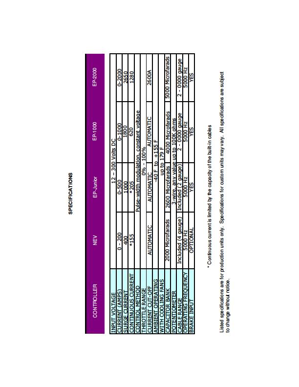
3 This manual covers the following EPC controllers: EP-2000 EP-1000 EP-Junior NEV Controller
4 INTRODUCTION The EP-Series of motor controllers are suitable for most industrial, automotive, and marine applications. They are designed to drive most brushed DC motors, including series-wound, separately excited, and permanent magnet motors. Some extremely low inductance motors may require software updates to prevent over-current conditions, which could inadvertently shut down your controller. All EP-Series controllers come configured to run off any DC power source, and can also be run from single-phase and three-phase AC power sources with our optional AC Module. All EPC controllers are designed to operate in harsh industrial environments. Installation is residential environments will require that the high voltage terminals of the unit to be shielded with a UL-Listed terminal protector or cover. All EPC Products are Manufactured in the United States of America
5 FEATURES True plug-and-play design... simply connect and go! Economical design results in an affordable controller - about half the cost of a conventional industrial/automotive controller Soft-start technology allows for smoother acceleration 100% Waterproof and wet-location compliant No programming required Fanless, air-cooled design allows offers a very small footprint Full optical isolation between high voltage and 12-volt systems Efficient heatsink and IGBT modules eliminate the need for liquid cooling Wide input voltage range: 24 to 320 volts Non-metallic enclosure increases safety and prevents corrosion All stainless steel / brass hardware included Energy-saving design operates at over 97% efficiency Brake pedal input for additional safety in the event of throttle bind / failure Built-in contactor delay allows you to turn on the contactors and controller at the same time, without the possibility of damaging the controller All EPC controllers automatically detect your motor type, battery pack voltage, and potentiometer range. There are no settings to adjust, switches to set, or any type of programming necessary. This allows you to make fast and easy changes to your electrical system without having to worry about re-programming your controller. All EPC controllers also use an interchangeable 6-pin wiring harness, which makes it very easy to swap or upgrade your controller --- without the need to replace your wiring harness.
6 INSTALLATION INSTRUCTIONS The recommended wire size will depend on your maximum load, however, we recommend that at least 2-gauge wire be used, regardless of how small the load is. The terminal allows for up to 4/0 wire to be used. HIGH POWER TERMINAL CONNECTION Please note that all RED terminals are POSITIVE (+) connections and all BLACK terminals are NEGATIVE (-) connections. All high power terminals use standard SAE 3/8 x 16 TPI studs, and come with brass or stainless steel nuts. The three large terminals on the EP-1000 are used to connect the motor and high voltage battery pack (or other power source). Two terminals connect to the motor, and one connects to the NEGATIVE terminal on your high voltage battery pack. This controller REQUIRES that a high power cable be connected from the POSTIVE terminal of the battery to the POSITIVE terminal of the motor. A typical installation is shown below.
7 SPECIAL NOTICE Always verify that NO HIGH VOLTAGE POTENTIAL is present on the 12 volt battery/power supply terminals. This can be dangerous to anyone servicing or using the equipment. Testing for this condition can be done as follows: Connect a high voltage meter between each 12 volt battery terminal (or power supply) and each high voltage battery terminal. The meter should read close to zero volts in all cases. For automotive applications, also check the voltage potential between the chassis/frame of the vehicle and each high voltage battery terminal. The meter should read close to zero volts in all cases. If there is a high voltage leak anywhere in the system, it must be repaired immediately. All EPC controllers are fully isolated, and cannot leak voltage into the 12-volt system.

8 LOW POWER TERMINAL CONNECTION All low power connections are pre-wired into a 6-pin wiring harness (see Figure 1) for easy installation. All EPC controllers use the same harness connector, and are interchangeable. This allows for fast and easy replacement and upgrading of your controller. Pin #1 (White Wire) Connect to the NEGATIVE (-) of your 12 VOLT power supply or battery. Pin #2 (Red Wire) Connect to the POSITIVE (+) of your 12 VOLT power source. This terminal is used to turn your controller ON. For electric vehicles, this is typically connected to the ignition switch. Pin #3 (Blue Wire) Brake Pedal Switch. Accepts +12V DC input to let the controller know that the brake pedal is depressed. This instructs the processor to go down to 0% throttle, regardless of the position of the potentiometer. If your motor is set to run continuously at idle, activating this wire will shut it down until the brake pedal is released Pin #4, 5, 6 (Green, Brown, and Yellow Wires) Connect to your 3-wire potentiometer. Most standard 5k through 100k potentiometers can be used. GREEN = 5V supply, YELLOW = Ground, and BROWN = potentiometer input. M = Male Pins F = Female Pins Figure 1: Controller End Wiring Harness
 may also be used, but wires number 6 and 4 must be reversed.")
9 POTENTIOMETER CONNECTION The EP-1000 will auto-detect any standard a 3-wire potentiometer. Rating from 0-5k to 0-100k can be used. Reverse potentiometers (5-0k or 10-0k, for example) may also be used, but wires number 6 and 4 must be reversed. In some cases, two-wire potentiometers (such as the Curtis PB-5 or PB-6) can also be used if you connect a wire from the third (unconnected) terminal of the potentiometer to the third terminal on the EP-1000 s throttle input (pin #6). To do this, you must first open the potentiometer s enclosure to gain access to the terminals and solder a wire to the unused potentiometer terminal. All EPC brand potentiometers are 3-wire, and come with a 6-pin EPC harness preinstalled. Due to their accuracy and high quality construction, we strongly recommend using only EPC potentiometer units with this controller. Low quality potentiometers can result in poor motor speed control, uneven throttle response, and often have a very short lifespan. Although an improperly connected potentiometer will not damage the controller itself, it could cause the controller to apply full power to the motor. This condition will cause the motor to operate at an unsafe speed, which could damage or even destroy the motor. Care should be taken not to power up the controller until proper installation of the potentiometer is verified. A diagnostic device (such as a duty cycle meter) can be used to show power output before connecting your motor. In some cases, a dummy load (such as a heater or light bulb) can be used in place of the motor, as long as the device is rated for the line voltage that you are using. Please call technical support at if you have difficulty with your potentiometer connections.

10 SAMPLE POTENTIOMETER CONNECTION NOTES: Do NOT Connect the PB-8 s microswitch to your contactor, as show in the Curtis manual. Doing so will DAMAGE your controller. EPC brand throttle boxes will plug directly into your controller. Splicing of the wiring harness will not be necessary.
11 SPEED CONTROL ADJUSTMENT The EP-1000 features soft-start technology, which automatically smoothes the controller s throttle response on take-off and deceleration. Several other factors will affect motor speed and response, including: - Total Potentiometer travel - Input voltage to the controller - Load on the motor Changing any of these values will affect the speed of the motor, however, the amount of power applied will always be controlled by the EP-1000 itself, based on the throttle (potentiometer) input. Potentiometers that have a longer travel tend to give more precise control of motor speed. For example, a potentiometer with a 4-inch travel will tend to have a much softer response that one with a 1-inch travel. The EP-1000 is pre-programmed from the factory with a linear throttle curve. This cannot be changed or modified by the end user. However, potentiometers with various output curves are available and can be used to adjust the throttle response.


12 CONTROLLER PROTECTION FUSE PROTECTION Fuse protection is strongly recommended for all EP Series controllers. Please note that a standard AC fuse can NOT be used in a DC circuit. The fuse must be SPECIFICALLY labeled for DC applications. For most standard applications, a 600A fuse will be sufficient. Application-specific fuses can be ordered directly from EPC. Also note that special-purpose 125-volt and 240-volt DC circuit breakers (such as the AirPax JLM-1-1RLS ) will NOT function properly and could lead to controller damage or failure due to internal arcing. Keep in mind that a DC motor s windings act as an inductor during normal operation. This could lead to a break voltage of several thousand volts, even in a 144-volt system. If using a circuit breaker, it must have a DC break rating higher than 600 volts. EPC recommends a minimum DC current rating of 1000 volts for all applications. Because of the very high cost of these large breakers, most users prefer to go with a conventional DC fuse. Although not resettable, a correctly-sized fuse should not blow under normal circumstances. And at less than 1/10 th of the cost of a resettable circuit breaker, they are very economical. NO YES NO
13 CONTROLLER PROTECTION The EP-1000 and EP-Junior controllers feature built-in software protection that prevents damage to the controller, regardless of what type of fault is detected on the output side. This effectively eliminates the possibility of controller damage/failure due to over-current, motor failure, and even dead short conditions on the output side (the EP-1000/EP-Junior can sustain a dead short on the output side indefinitely). With this in mind, it is important to note that DC motor controllers are NOT indestructible. Routinely subjecting controllers to voltages outside of their normal range can damage internal components, and possibly caused a delayed failure. CAUTION NEVER disconnect and reconnect the HIGH VOLTAGE power to the controller during operation! Doing so can cause immediate controller damage and/or failure! Any intermittent interruption of power (poor connections, arcing, etc.) between the BATTERY PACK and CONTROLLER during normal operation can destroy the IGBT modules inside the unit. This type of failure is NOT covered under warranty. Due to internal electronic protection, arcing between the CONTROLLER and MOTOR will NOT damage your controller. However, this condition can lead to other problems including melted cables, motor damage/failure, and in some cases can even cause fires. This is why we strongly recommend checking your cables and connections for signs of arcing on a regular basis. Arcing/power interruptions in the system can be caused by: - Loose terminals - Faulty contactor(s) - Bad cables/crimps - Bad connections between batteries in the pack - Short circuiting of battery pack wiring

14 CONTACTORS A pair of contactors, or some other type of high-speed mechanical disconnect should be installed near the power supply of the controller. This not only allows for easy servicing, but can protect the motor and controller in the event of a short or system failure. Contactors are REQUIRED for all electric vehicles running DC motors. Pictured is a Curtis SW-200 Contractor. Contactors should have a continuous rating of at least 200 amps, with a surge capacity of about 1000 for this controller. Magnetic blowouts are required. For electric vehicles, both the positive and negative contactors should turn on and off AT THE SAME TIME as your controller. Typically, both the controller and contactor circuits are connected to the ignition switch. Cycling or engaging a contactor while the controller is operating can DAMAGE THE CONTROLLER, especially when a motor is connected. Please note that when you power up the controller, there is a one second delay which allows the contactors to fully engage. This protects the controller in the event of arcing during the contactor engagement. A pre-charge resistor can help eliminate contactor arcing and prolong the life of the contactors. Although a pre-charge resistor is not required for this controller, we do recommend using one when possible.


15 WET LOCATIONS Although all EPC controllers are water resistant, care should be taken during installation to protect any exposed high voltage terminals. The standard NEMA enclosure used for all EPC controllers protects the internal components, and is completely sealed from the environment. EP-1000 / EP-2000 The EP-1000 may be briefly submersed while running. All external connections should be protected from the environment by installing optional protection boots, as shown here. These boots are available from directly from EPC and most other industrial component suppliers. EP-Junior / NEV Controller The EP-Junior and Neighborhood Electric Vehicle controllers come with pre-installed motor and battery cables for easy installation. The cables are installed using water-tight connections, as shown to the right. This allows the controller to operate while submersed, without the possibility of voltage leaking into the water.
16 OPTIONAL EQUIPMENT AC LINE KIT Allows use of the EP-1000 with any single-phase or three-phase AC power sources up to 240 volts. Can be used with up to 600 volts for modified units. EXTERNAL DC FUSE Helps protect both the motor and controller during stall loads and in the event of an external short circuit. DC fuses are available in 200 to 800 amps. Recommended for battery applications that do not have built-in fuse protection. CAPACITOR BANK An external capacitor bank is recommended for applications that are subject to severe voltage and power fluctuations.
17
EPC. DC Motor Speed Control TECHNICAL REFERENCE MANUAL
 EPC DC Motor Speed Control TECHNICAL REFERENCE MANUAL This manual covers the following EPC controllers: EP-2000 EP-1000 EP-Junior NEV Controller INTRODUCTION The EP-Series of motor controllers are suitable
OPERATION AND INSTRUCTION MANUAL. EP Series. Battery Chargers and Power Supplies
 OPERATION AND INSTRUCTION MANUAL EP Series Battery Chargers and Power Supplies THIS MANUAL IS PUBLISHED BY EPC CORPORATION AND IS TO BE DISTRIBUTED WITH NEW DEVICES ONLY NO OTHER DISTRIBUTION IS PERMITED
Kelly HSR Series Motor Controller with Regen User s Manual V 3.3. Kelly HSR Opto-Isolated Series Motor Controller with Regen.
 Kelly HSR Opto-Isolated Series Motor Controller with Regen User s Manual HSR72601 HSR72801 HSR12401 HSR12601 HSR12901 HSR14301 HSR14501 HSR14701 Rev.3.3 Dec. 2011 Contents Chapter 1 Introduction... 2 1.1
ATOTH-G Series BLDC Motor Controller. User s Manual
 ATOTH-G Series BLDC Motor Controller User s Manual Contents Chapter One Summary...1 Chapter Two Main Features and Specifications.2 2.1 Basic Functions...2 2.2 Features... 5 2.3 Specifications...6 Chapter
SHORT-STOP. Electronic Motor Brake Type G. Instructions and Setup Manual
 Electronic Motor Brake Type G Instructions and Setup Manual Table of Contents Table of Contents Electronic Motor Brake Type G... 1 1. INTRODUCTION... 2 2. DESCRIPTION AND APPLICATIONS... 2 3. SAFETY NOTES...
Full Bridge Permanent Magnet DC Motor Controller User's Manual
 www.igreatway.com Email:info@igreatway.com V 3.3 Full Bridge Permanent Magnet DC Motor Controller User's Manual PM24101 PM24201 PM24301 PM36101 PM36201 PM48101 PM48201 PM48301 PM48401B PM48501B PM72101
INSTALLATION MANUAL AP60B INSTALLATION MANUAL
 INSTALLATION MANUAL 2. TOOLS REQUIRED The following is a list of tools required to properly install the cruise control. While this unit may be installed without some of the tools listed, it is recommended
Small Full Bridge Permanent Magnet Motor DC Controller User Manual
 Small Full Bridge Permanent Magnet Motor DC Controller User Manual SPM24051X SPM24101X SPM24121X SPM48051X SPM48101X SPM48121X SPM72051X SPM72101X SPM72121X SPM48151E SPM48181E SPM48221E SPM72151E SPM72181E
Kelly HPM High Power Full Bridge Permanent Magnet DC Motor Controller User s Manual
 Kelly HPM High Power Full Bridge Permanent Magnet DC Motor Controller User s Manual HPM72601 HPM72801 HPM12401 HPM12601 HPM12801 HPM14301 HPM14501 HPM14701 Rev.3.4 Dec. 2016 Contents Chapter1 Introduction...
Kelly KDHA High Voltage Series/PM Motor Controller User s Manual
 Kelly KDHA High Voltage Series/PM Motor Controller User s Manual KDH07500A KDH07501A KDH07700A KDH07701A KDH09400A KDH09401A KDH09500A KDH09501A KDH12400A KDH12401A KDH12500A KDH12501A KDH14300A KDH14301A
STARTING SYSTEMS 8B - 1 STARTING SYSTEMS CONTENTS
 TJ STARTING SYSTEMS 8B - 1 STARTING SYSTEMS CONTENTS page DESCRIPTION AND OPERATION STARTER MOTOR... 2 STARTER RELAY... 3 STARTING SYSTEM... 1 DIAGNOSIS AND TESTING STARTER MOTOR... 8 STARTER MOTOR NOISE
Easy Start. 364 (3 ton) Soft Starter 368 (6 ton) Soft Starter. Installation Manual
 Soft Starter 368 (6 ton) Soft Starter. Installation Manual") Easy Start 364 (3 ton) Soft Starter 368 (6 ton) Soft Starter Installation Manual Micro Air Corporation Phone (609) 259-2636 124 Route 526. www.microair.net Allentown NJ 08501 Fax (609) 259-6601 Retrofit
Easy Start 364 (3 ton) Soft Starter 368 (6 ton) Soft Starter Installation Manual Micro Air Corporation Phone (609) 259-2636 124 Route 526. www.microair.net Allentown NJ 08501 Fax (609) 259-6601 Retrofit
Kelly KDC Series/PM Motor Controller User s Manual
 Kelly KDC Series/PM Motor Controller User s Manual KDC48600 KDC48601 KDC48602 KDC48603 KDC72600 KDC72601 KDC72602 KDC72603 KDC72800 KDC72801 KDC72802 KDC72803 KDC12602 KDC12603 Rev.3.3 May 2011 Contents
Elite Power Solutions Automatic Battery Control (ABC) Operation Manual
 Operation Manual") Elite Power Solutions Automatic Battery Control (ABC) Operation Manual Elite Power Solutions 335 E Warner Rd. STE 3 Chandler, AZ 85225 www.elitepowersolutions.com ABC Operation Manual Page 1 Table of Contents
Elite Power Solutions Automatic Battery Control (ABC) Operation Manual Elite Power Solutions 335 E Warner Rd. STE 3 Chandler, AZ 85225 www.elitepowersolutions.com ABC Operation Manual Page 1 Table of Contents
CradlePoint Vehicle Best Practices Installation Guide
 CradlePoint Vehicle Best Practices Installation Guide Using CradlePoint Routers in 12V and 24V Vehicles Revision 1.2 Overview The automotive environment can be particularly harsh for electrical equipment
GENESIS Electronic Brake Controller Hayes Brake Controller Company - P/N 81790
 GENESIS Electronic Brake Controller Hayes Brake Controller Company - P/N 81790 INSTALLATION MANUAL For trailers with 2-8 electric brakes and vehicles with 12 volt negative ground systems only. READ AND
VEHICLE SPEED CONTROL SYSTEM
 J VEHICLE SPEED CONTROL SYSTEM 8H - 1 VEHICLE SPEED CONTROL SYSTEM CONTENTS page DIAGNOSIS... 2 GENERAL INFORMATION... 1 page SERVICE PROCEDURES... 9 GENERAL INFORMATION The vehicle speed control system
Brushed. Brushed. Brushed Motor
 Kelly Kelly Kelly Kelly KD KD KD KD Series Series Series Series DC DC DC DC Motor Motor Motor Motor Controller Controller Controller Controller User User User User s Manual Manual Manual Manual V 2.5 2.5
Disconnect the battery power from the car.
 Adding a safety fuse to the ignition circuit of 1956 to 1962 Corvettes Part 1 is for 1958 to 1962. Part 2 is for 1956 to 1957 Rich Mozzetta and Dave Zuberer Part 1-1958 to 1962 Here is a way to add a fuse
Filtered PWM Speed Control for Permanent Magnet DC Motors
 Instructions for Installation and Operation Filtered PWM Speed Control for Permanent Magnet DC Motors Model 0794 Speed and Direction Control up to 5/8 HP NEMA-1/IP-20 Specifications Product Type:... WPM-2148E1
ALTERNATOR PRECAUTIONS. Some precautions should be taken when working on this, or any other, AC charging system.
 The alternator charging system is a negative (-) ground system which consists of an alternator, a regulator, a charge indicator, a storage battery and wiring connecting the components, and fuse link wire.
Devices Supported: KEB48220 KEB48221 KEB48300 KEB48301 KEB48400 KEB48401 KEB48600 KEB48601 KEB72330 EB KEB72450 KEB EB KEB72600 KEB
 Kelly KEB Brushless Motor Controller User s Manual Devices Supported: KEB48220 KEB48221 KEB48300 KEB48301 KEB48400 KEB48401 KEB48600 KEB48601 KEB72330 KEB EB72 72331 KEB72450 KEB EB72 72451 KEB72600 KEB
Kelly KBS Brushless Motor Controller User s Manual
 Kelly KBS Brushless Motor Controller User s Manual Devices Supported: KBS24051L KBS24101L KBS24121L KBS36051L KBS36101L KBS48051L KBS48101L KBS48121L KBS72051L KBS72101L KBS72121L KBS24051X KBS24101X KBS24121X
CALTRAP INSTALLATION AND OPERATIONS MANUAL
 INSTALLATION AND OPERATIONS MANUAL NOTE Please read this entire installation and operations manual before energizing the. Safety Considerations: Installing and servicing capacitor equipment can be hazardous.
CAUTION: READ INSTRUCTIONS CAREFULLY BEFORE STARTING INSTALLATION
 V-Twin MFG. VT No. 32-9500 V-TECH 1 IGNITION KIT, SINGLE FIRE FITS EV SHOVEL, XL THRU 1997 VT No. 32-9503 V-TECH 1 IGNITION KIT, SINGLE FIRE FITS EV, SHOVEL, XL, WITH COIL AND WIRES This is a custom application
RECOMMENDED TOOLS PERSONAL & VEHICLE PROTECTION SAFETY GLASSES
 PART NUMBER: 250-9631 GENERAL APPLICABILITY THIS CRUISE WAS TESTED AND VERIFIED ON: ALL MODELS (AT/MT) RECOMMENDED TOOLS PERSONAL & VEHICLE PROTECTION SAFETY GLASSES KIT CONTENTS/SERVICE PARTS ITEM QTY
BX88175 Installation Instructions ToadStop II Vacuum Brake System
 BX88175 Installation Instructions ToadStop II Vacuum Brake System Serial No. Customer supplied tools & supplies Utility knife, 12VDC tester, drill & bits: (1/8", 1/4", 5/8 ), ¼ socket drive bit, punch,
RECOMMENDED TOOLS PERSONAL & VEHICLE PROTECTION SAFETY GLASSES
 2014 FORD TRANSIT FULL SIZE PART NUMBER: 250-9636 GENERAL APPLICABILITY THIS CRUISE WAS TESTED AND VERIFIED ON: FORD TRANSIT 150, 250 RECOMMENDED TOOLS PERSONAL & VEHICLE PROTECTION SAFETY GLASSES KIT
INSTALLATION INSTRUCTION
 1551 S. Vineyard Avenue Ontario, CA 91761 (909) 923-1973 INSTALLATION INSTRUCTION Club Car Precedent Installation Notes CURTIS 1234, 1236 OR 1238 AC INDUCTION MOTOR/ CONTROLLER REVISION: B This kit is
Digitrip Retrofit System for ITE K-3000, K-3000 S, K-4000 and K-4000 S Breakers
 Supersedes IL 33-858-4 Dated 05/02 Digitrip Retrofit System for ITE K-3000, K-3000 S, K-4000 and K-4000 S Breakers Digitrip Retrofit System for ITE K-3000, Digitrip Retrofit System for ITE K-3000, K-3000
DTC P0A04 - Open Wiring Fault
 DTC P0A04 - Open Wiring Fault Orion Product Orion BMS [Original] (24-180 Cell) Orion BMS 2 (24-180 Cell) Orion JR (16 Cell) Fault Supported YES YES YES FAULT DESCRIPTION This fault is a serious code that
Symptom: P0068-MANIFOLD PRESSURE/THROTTLE POSITION CORRELA- TION - VACUUM LEAK DETECTED
 Symptom: P0068-MANIFOLD PRESSURE/THROTTLE POSITION CORRELA- TION - VACUUM LEAK DETECTED When Monitored and Set Condition: VAC- UUM LEAK DETECTED When Monitored: During all drive modes. Set Condition: If
RECOMMENDED TOOLS PERSONAL & VEHICLE PROTECTION SAFETY GLASSES
 PART NUMBER: 250-9625 GENERAL APPLICABILITY THIS CRUISE WAS TESTED AND VERIFIED ON: ALL MODELS RECOMMENDED TOOLS PERSONAL & VEHICLE PROTECTION SAFETY GLASSES KIT CONTENTS/SERVICE PARTS ITEM QTY DESCRIPTION
MASTERsine Inverter PXA Series Installation Guide
 Backup Power System Expert TM MASTERsine Inverter PXA Series Installation Guide Important Safety Instructions IMPORTANT: Read and save this Installation Guide for future reference. This chapter contains
INSTALLATION INSTRUCTIONS
 1551 S. Vineyard Avenue Ontario, CA 91761 (909) 923-1973 INSTALLATION INSTRUCTIONS E-Z-GO Installation Notes CURTIS 1234, 1236 OR 1238 AC INDUCTION MOTOR/ CONTROLLER EZ-GO Curtis Controller Installation
INOVA HIGHTECH Ltd. MEP 002/003 Auto Starter Manual
 INOVA HIGHTECH Ltd. MEP 002/003 Auto Starter Manual Complete Installation and Operating Manual for the MEP 002/003 Auto / Remote Starter for the following MEP Power Generators: MEP 002A/003A/011A/802A/803A/811A
I N C O R P O R A T E D
 I N C O R P O R A T E D Table of Contents 1. Overview 2 2. Specifications 2 3. Operating Instructions 3.1 Pressure Sealing 3 3.2 Installation 3 3.3 AutoPSI Interface Unit 4 4. Static Pressure Calibration
EasyStart 364 (ASY-364-X20-IP) Installation Instructions for the Coleman / Airxcel Air Conditioners
 Installation Instructions for the Coleman / Airxcel Air Conditioners") EasyStart 364 (ASY-364-X20-IP) Installation Instructions for the Coleman / Airxcel Air Conditioners using Installation Kit KIT-364-CM1 Contents Introduction... 2 Safety first... 2 Making a good crimp...
EasyStart 364 (ASY-364-X20-IP) Installation Instructions for the Coleman / Airxcel Air Conditioners using Installation Kit KIT-364-CM1 Contents Introduction... 2 Safety first... 2 Making a good crimp...
VAGABOND S HANDBOOK TRANSMISSION
 03/24/07 TRANSMISSION Transmission won t engage into Gear This is caused usually by too low a Voltage to get into the ECM. This unit requires a minimum of 9VDC in order to operate at all. Almost all erratic
team master medium voltage solid state starters
 team master medium voltage solid state starters The Today s global economy is in many ways driven by the AC Induction Motor. Industrial facilities worldwide depend on these motors to drive the machinery
INSTALLATION & OPERATION MANUAL
 INSTALLATION & OPERATION MANUAL PRE-ASSEMBLED PRIMARY & BATTERY BACK-UP SUMP PUMP SYSTEM 5030CVSPBUSS, 5033CVSPBUSS www.aymcdonald.com A.Y. McDonald BBU Manual Revised 8-13 3210-479 Rev. A 12 This pump
CRUISE CONTROL SYSTEM
 CRUISE CONTROL SYSTEM 1994 Toyota Celica 1994 ACCESSORIES & EQUIPMENT Toyota Motor Sales, U.S.A., Inc. - Cruise Control Systems Celica DESCRIPTION Cruise control system consists of Cruise Control Electronic
Electrical Energy and Power Ratings
 Section 1 - From the Wall Socket Electrical Energy and ower Ratings Batteries and the mains are sources of electrical energy. Electrical appliances can then convert this into other forms of energy. e.g.
Service Manual. Extractor Model XR28QP. For The. For: Troubleshooting Adjustments
 Service Manual For The X Ride 28 Rider Extractor Model XR28QP For: Training Troubleshooting Adjustments Contents 1 Cautions ------------------------------------------------------------------------------
CHARGING SYSTEM 8C - 1 CHARGING SYSTEM CONTENTS
 ZG CHARGING SYSTEM 8C - 1 CHARGING SYSTEM CONTENTS page GENERAL INFORMATION OVERVIEW... 1 DESCRIPTION AND OPERATION BATTERY TEMPERATURE SENSOR... 2 CHARGING SYSTEM OPERATION... 1 ELECTRONIC VOLTAGE REGULATOR...
RECOMMENDED TOOLS PERSONAL & VEHICLE PROTECTION SAFETY GLASSES
 PART NUMBER: 250-9627 GENERAL APPLICABILITY THIS CRUISE WAS TESTED AND VERIFIED ON: ALL MODELS (AT/MT) RECOMMENDED TOOLS PERSONAL & VEHICLE PROTECTION SAFETY GLASSES KIT CONTENTS/SERVICE PARTS ITEM QTY
Electric Motor Controls BOMA Pre-Quiz
 Electric Motor Controls BOMA Pre-Quiz Name: 1. How does a U.P.S. (uninterruptable power supply) work? A. AC rectified to DC batteries then inverted to AC B. Batteries generate DC power C. Generator, batteries,
RECOMMENDED TOOLS PERSONAL & VEHICLE PROTECTION SAFETY GLASSES
 PART NUMBER: 250-9545 GENERAL APPLICABILITY THIS CRUISE WAS TESTED AND VERIFIED ON:2.7,3.3, 3.5, 5.0 FORD F-150 RECOMMENDED TOOLS PERSONAL & VEHICLE PROTECTION SAFETY GLASSES KIT CONTENTS/SERVICE PARTS
MAGNETIC MOTOR STARTERS
 Chapter 6 MAGNETIC MOTOR STARTERS 1 The basic use for the magnetic contactor is for switching power in resistance heating elements, lighting, magnetic brakes, or heavy industrial solenoids. Contactors
RECOMMENDED TOOLS PERSONAL & VEHICLE PROTECTION SAFETY GLASSES
 HYUNDAI ACCENT 2010- /ELANTRA 2012- / KIA RIO 2012- PART NUMBER: 250-9628-NS GENERAL APPLICABILITY THIS CRUISE WAS TESTED AND VERIFIED ON: (AT/MT) VEHICLES RECOMMENDED TOOLS PERSONAL & VEHICLE PROTECTION
INSTALLATION INSTRUCTIONS. Yamaha G19 Installation Notes
 620 Magnolia Avenue Suite B Ontario, CA 91762 (909) 923-1973 INSTALLATION INSTRUCTIONS Yamaha G19 Installation Notes CURTIS 1232, 1234, 1236 OR 1238 AC INDUCTION MOTOR/ CONTROLLER Yamaha G 19 Installation
Types of Motor Starters There are several types of motor starters. However, the two most basic types of these electrical devices are:
 Introduction Motor starters are one of the major inventions for motor control applications. As the name suggests, a starter is an electrical device which controls the electrical power for starting a motor.
CONTROLLER DIAGNOSTIC GUIDE
 Proprietary tice: This document contains proprietary information which not to be reproduced, transferred, to other documents, disclosed to others, used for manufacturing or any other purpose without the
SUPPLEMENTAL RESTRAINT SYSTEM (SRS)
") 52B-1 SUPPLEMENTAL RESTRAINT SYSTEM (SRS) CONTENTS GENERAL INFORMATION................ 2 SRS SERVICE PRECAUTIONS........... 3 SPECIAL TOOLS........................ 5 TEST EQUIPMENT......................
52B-1 SUPPLEMENTAL RESTRAINT SYSTEM (SRS) CONTENTS GENERAL INFORMATION................ 2 SRS SERVICE PRECAUTIONS........... 3 SPECIAL TOOLS........................ 5 TEST EQUIPMENT......................
Battery Control Center - Diesel
 Service Manual CAUTION: All servicing of the Battery Control Center should be done only by a qualified Service Technician. Inadvertent shorts inside the Battery Control Center could result in severe damage
Typical Install Instructions
 Typical Install Instructions Read & understand all steps of these instructions before beginning this installation. WEBER Conversion Kit, VW T-1/2, up to 1835cc 32 / 36 DFEV Weber Carburetor These instructions
C FORD F250 / F L POWERSTROKE DIESEL WITH AUTOMATIC TRANSMISSIONS ONLY
 EXHAUST BRAKES C40019 1999-2003 FORD F250 / F350 7.3L POWERSTROKE DIESEL WITH AUTOMATIC TRANSMISSIONS ONLY Getting Started Thank you and congratulations on your purchase of a Pacbrake exhaust retarder.
RECOMMENDED TOOLS PERSONAL & VEHICLE PROTECTION SAFETY GLASSES
 PART NUMBER: 250-9625 GENERAL APPLICABILITY THIS CRUISE WAS TESTED AND VERIFIED ON: ALL MODELS RECOMMENDED TOOLS PERSONAL & VEHICLE PROTECTION SAFETY GLASSES KIT CONTENTS/SERVICE PARTS ITEM QTY DESCRIPTION
RECOMMENDED TOOLS PERSONAL & VEHICLE PROTECTION SAFETY GLASSES
 MITSUBISHI MIRAGE 2013- PART NUMBER: 250-9633 GENERAL APPLICABILITY ALL MODELS RECOMMENDED TOOLS PERSONAL & VEHICLE PROTECTION SAFETY GLASSES KIT CONTENTS/SERVICE PARTS ITEM QTY DESCRIPTION PART# 1 1 CRUISE
INDEX Section Page Number Remarks
 INDEX Section Page Number Remarks Synchronous Alternators 2 4 General Fault Finding Capacitors 5 6 Fault Finding & Testing Diodes,Varistors, EMC capacitors & Recifiers 7 10 Fault Finding & Testing Rotors
Installation and Construction Notes for EVSE4
 Installation and Construction Notes for EVSE4 You need to read and understand this if you want to build an EVSE that will be safe and need to pass a building inspectors review. Before beginning this process
SD Bendix ET-2 Electronic Treadle DESCRIPTION OPERATION
 SD-15-4106 Bendix ET-2 Electronic Treadle PIVOT SPRING MOUNTING BASE DESCRIPTION CONNECTOR FIGURE 1 - ET-2 ELECTRONIC TREADLE ROLLER TREADLE COVER DOUBLE RETURN SPRING CABLE ASSEMBLY The ET-2 is an electronic
Burden Fuse Rating Resistor SAF / SAK6 1NM 10mm M8 12NM SAF / SAK10 2NM 16mm M8 12NM
 Contents Section Page 1.0 Introduction 1 2.0 Specification 1-4 3.0 Installation 5-8 4.0 Programming 9-10 5.0 Menus 10-12 6.0 Fault Finding/Diagnostics 12-13 7.0 Communication 13 8.0 Setting Up 13-16 1.0
2015 EDITION SUBMERSIBLE MOTORS AIM MANUAL. APPLICATION INSTALLATION MAINTENANCE 60 Hz, Single-Phase and Three-Phase Motors. franklinwater.
 0 EDITION AIM MANUAL SUBMERSIBLE MORS APPLICATION INSTALLATION 60 Hz, Single-Phase and Three-Phase Motors franklinwater.com All Motors System Troubleshooting Motor Does Not Start A. No power or incorrect
Xebra Electrical Component Locations
 Xebra Electrical Component Locations Last updated on April 12, 2007 Copyright 2007. This document my not be reprinted, published, emailed or posted on the Internet without the approval of ZAP. Component
SPEED CONTROL SYSTEM
 DN SPEED CONTROL SYSTEM 8H - 1 SPEED CONTROL SYSTEM TABLE OF CONTENTS page AND SPEED CONTROL SYSTEM...1 SPEED CONTROL SERVO....2 SPEED CONTROL SOLENOID CIRCUITS...2 SPEED CONTROL SWITCHES...2 BRAKE LAMP
Advanced EasyStart Troubleshooting
 Advanced EasyStart Troubleshooting EasyStart is designed for excellent reliability and durability. Every EasyStart is tested on a compressor before it leaves Micro-Air to ensure it will work when delivered.
BMW K1200LT / K1200RS Testing a Throttle Position Sensor (also called TPS)
") BMW K1200LT / K1200RS Testing a Throttle Position Sensor (also called TPS) Many hours were spent to test and validate the information furnished in this document. None of this information should be considered
BMW K1200LT / K1200RS Testing a Throttle Position Sensor (also called TPS) Many hours were spent to test and validate the information furnished in this document. None of this information should be considered
Installation and Operating Instructions
 PUMP PROTECTION SYSTEM Installation and Operating Instructions Congratulations on your purchase of a Franklin Electric pump protection system. Pumptec-Plus is the most sophisticated pump protection system
UNIVERSAL ELECTRA-STEER FOR 2 COLUMN 220w Plain w Polished w Plain w Polished
 UNIVERSAL ELECTRA-STEER FOR 2 COLUMN 220w Plain 8052810 220w Polished 8052610 360w Plain 8052780 360w Polished 8052760 Full refund will NOT be granted to any kits that are damaged, scratched, or altered
Idle Timer Controller - ITC515-A Ford Transit Contact InterMotive for additional vehicle applications
 An ISO 9001:2008 Registered Company Idle Timer Controller - ITC515-A 2015-2018 Ford Transit Contact InterMotive for additional vehicle applications Overview The ITC515-A system will shut off gas or diesel
Model No. SB1B-14 Linear Standby Regulator. B & C Specialty Products P.O. Box B Newton, KS (316)
") Installation Instructions for Model No. SB1B-14 Linear Standby Regulator With Over-Voltage Protection B & C Specialty Products P.O. Box B Newton, KS 67114 (316) 283-8000 SB1B-14_Install, Rev. A (12/12/14)
Installation Instructions for Model No. SB1B-14 Linear Standby Regulator With Over-Voltage Protection B & C Specialty Products P.O. Box B Newton, KS 67114 (316) 283-8000 SB1B-14_Install, Rev. A (12/12/14)
User Manual. T6 Tachometer. Online: Telephone: P.O. Box St. Petersburg, Florida 33736
 User Manual T6 Tachometer Online: www.phareselectronics.com Telephone: 727-623-0894 P.O. Box 67251 St. Petersburg, Florida 33736 Table of Contents Overview... 1 Description... 1 Wiring... 1 T6 Tachometer
BLACKBIRD WIRING MANUAL
 BLACKBIRD WIRING MANUAL VERSION ZX120 5/09 TO BE USED IN CONJUNCTION WITH A VEHICLE-SPECIFIC INSTALLATION SUPPLEMENT System Capabilities The 5kW Blackbird will provide 42 amperes of 120 Volt alternating
DOC # DOCSST-D 08/16/99
 DOC # DOCSST-D 08/16/99 Wired Rite Systems 5793 Suite A, Skylane Blvd., Windsor Ca. 95492 Phone: (800) 538-7483 Or (707) 838-1122 Fax: (800) 525-7483 WEB: http://www.wiredrite.com E-MAIL: Info@wiredrite.com
Design Standards NEMA
 Design Standards Although several organizations are involved in establishing standards for the design, construction, and application of motor control centers, the primary standards are established by UL,
B-03 ELECTRICIAN TRAINING SKILL DEVELOPMENT GUIDE
 B-03 ELECTRICIAN TRAINING SKILL DEVELOPMENT GUIDE Duty B: Power Distribution (600V and below) B-03: Troubleshoot 480V System Issued 06/01/98 Task Preview Troubleshoot 480V System The 480V distribution
RECOMMENDED TOOLS PERSONAL & VEHICLE PROTECTION SAFETY GLASSES
 PART NUMBER: 250-9618 AUTOMATIC TRANSMISSION 250-9619 MANUAL TRANSMISSION GENERAL APPLICABILITY THIS CRUISE WAS TESTED AND VERIFIED ON: CHEVY SONIC/ SPARK (ALL MODELS) RECOMMENDED TOOLS PERSONAL & VEHICLE
INSTALLATION INSTRUCTIONS
 INSTALLATION INSTRUCTIONS WARNING: WARNING: www.altronicinc.com DEVIATION DEVIATION FROM THESE FROM INSTRUCTIONS THESE INSTRUCTIONS MAY LEAD MAY TO LEAD IMPROPER TO IMPROPER OP- ERATION OF ENGINE THE MACHINE
D&D Motor Systems, Inc.
 D&D Motor Systems, Inc. Programmable Regen Controller Manual & Schematics BE ADVISED, D&D Motor Systems, Inc. does not design and manufacture controllers. We provide them as an extension to our existing
VoltPro VP4 Automatic Voltage Regulator
 VoltPro VP4 Automatic Voltage Regulator The VoltPro VP4 Automatic Voltage Regulator is an affordable generator voltage regulator that is designed for the consumer market and can replace many popular voltage
ALTERNATOR - BOSCH 35/75-AMP & 40/90-AMP
 ALTERNATOR - BOSCH 35/75-AMP & 40/90-AMP 1988 Chrysler LeBaron Convert/Coupe 1988 ALTERNATORS & REGULATORS Chrysler Motors - Bosch 35/75 & 40/90 Amp Alternator All Models DESCRIPTION The charging system
MD10. Engine Controller. Installation and User Manual for the MD10 Engine Controller. Full Version
 MD10 Engine Controller Installation and User Manual for the MD10 Engine Controller. Full Version File: MartinMD10rev1.4.doc May 16, 2002 2 READ MANUAL BEFORE INSTALLING UNIT Receipt of shipment and warranty
Aftermarket Interface Module
 An ISO 9001:2008 Registered Company Aftermarket Interface Module (2015-2018 Ford Transit) AIM514-B High Side Solenoid type Coolant Valve Control AIM515-B Motor Reversing type Coolant Valve Control Introduction
INSTALLATION INSTRUCTIONS for HI-4 DUAL FIRE MOTORCYCLE IGNITION. Part Number INTRODUCTION REMOVAL OF POINTS IGNITION TO 1977 MODELS
 INSTALLATION INSTRUCTIONS for HI- DUAL FIRE MOTORCYCLE IGNITION Part Number -00 CAUTION: READ INSTRUCTIONS CAREFULLY BEFORE STARTING INSTALLATION INTRODUCTION The HI- ignition system is intended for use
English - Español - Français - Deutsch - Italiano
 English - Español - Français - Deutsch - Italiano INTRODUCTION Thank you for purchasing Power Probe products. The Power Probe is the best professional electrical tester for reducing diagnostic time in
WOT Box Installation Instructions VW / Audi
 Connector Pinout Pin Color AWG Name WOT Box Installation Instructions VW / Audi Description 1 Yellow 18 RPM Connect to Fuel Injector Drive Signal or Ignition Control Signal (varies by car model) 2 Black
Control. Part B, Section 2. This section covers the following unit configurations. 3400V 3500V. Voltage 4. Pump Piston (E, F, G)
") Part B, Section 2 Model This section covers the following unit configurations. Voltage 4 3100V 3400V 3500V Pump Piston (E, F, G) Manifold 4-Port (A) 6-Port (B, C) 2-Port (S, T) Vista Standard (V) B 2-0
Part B, Section 2 Model This section covers the following unit configurations. Voltage 4 3100V 3400V 3500V Pump Piston (E, F, G) Manifold 4-Port (A) 6-Port (B, C) 2-Port (S, T) Vista Standard (V) B 2-0
ARM V FDBK ENSURE MOTOR IS NOT ROTATING DURING POWER UP STILL FAULTS? YES ENSURE ARMATURE WIRING IS ISOLATED FROM ANY OTHER POWER LEADS STILL FAULTS?
 ARM V FDBK ENSURE MOTOR IS T ROTATING DURING POWER UP This fault can only happen in the first 3 seconds after power up. The processor looks at the armature voltage. The voltage needs to be near 0. Possible
Pretest Module 21 Units 1-4 AC Generators & Three-Phase Motors
 Pretest Module 21 Units 1-4 AC Generators & Three-Phase Motors 1. What are the two main parts of a three-phase motor? Stator and Rotor 2. Which part of a three-phase squirrel-cage induction motor is a
Installing Ignition Coil relay
 Installing Ignition Coil relay Above is a schematic diagram of the coil relay modification. All it really does is, it uses the existing 12 Volt positive that normally powers the coils, to power a relay,
RECOMMENDED TOOLS PERSONAL & VEHICLE PROTECTION SAFETY GLASSES
 GENERAL APPLICABILITY NISSAN SENTRA (AT/MT) RECOMMENDED TOOLS PERSONAL & VEHICLE PROTECTION SAFETY GLASSES KIT CONTENTS/SERVICE PARTS ITEM QTY DESCRIPTION PART# 1 1 CRUISE CONTROL MODULE 250-2809 2 1 CLUTCH
Electrical Systems. Introduction
 Electrical Systems Figure 1. Major Components of the Car s Electrical System Introduction Electricity is used in nearly all systems of the automobile (Figure 1). It is much easier to understand what electricity
SAISBM V36W Installation Instructions
 The Original Secondary Air Injection System Bypass Kit SAISBM V36W Installation Instructions All Applicable Toyota/Lexus Vehicles Introduction: The Secondary Air Injection System (SAIS) bypass module is
Dankoff LCB Solar Pump & Fan Controller. INSTRUCTIONS For INSTALLATION and OPERATION
 Dankoff LCB Solar Pump & Fan Controller INSTRUCTIONS For INSTALLATION and OPERATION Model DL-8B Model DL-16B Model DL-10B CUSTOM Models (8 amp, 12/24V) Item ISS-11065 (16 amp, 12/24V) Item ISS-11066 (10
1 of 14 9/4/2016 4:05 PM
 1 of 14 9/4/2016 4:05 PM P0068-MANIFOLD PRESSURE/THROTTLE POSITION CORRELATION P0068-Manifold Pressure/Throttle Position Correlation Theory of Operation This DTC sets when an unexpected high intake manifold
RECOMMENDED TOOLS PERSONAL & VEHICLE PROTECTION SAFETY GLASSES
 GENERAL APPLICABILITY FORD FIESTA ( AT/MT) KIT CONTENTS/SERVICE PARTS ITEM QTY DESCRIPTION PART# 1 1 CRUISE CONTROL MODULE 250-2813 2 1 SWITCH HARNESS 250-2760 3 1 PEDAL INTERFACE HARNESS 250-2821 4 1
AC Rectifiers for use with Armature Actuated Brakes. Product Overview. Full Wave. Half Wave. Combination Full and Half Wave. TOR-AC Full and Half Wave
 Rectifiers for use with Armature Actuated Brakes Product Overview NOTE: For brake response times with and without rectifiers see page 94. Full Wave A rectifier in which both positive and negative half-cycles
********SERVICE MANUAL********* MODELS:
 ********SERVICE MANUAL********* MODELS: -------------- 7553-70 Variable Speed Drive/Controller System, 600 rpm, 115v 7553-71 Variable Speed Controller only, 600 rpm,115v 7553-80 Variable Speed Drive/Controller
MGL Avionics AvioGuard. Fault protected, wide input range, isolated, DC to DC converter for avionics applications
 MGL Avionics AvioGuard Fault protected, wide input range, isolated, DC to DC converter for avionics applications General The MGL Avionics AvioGuard is a fault protected DC to DC converter. It is able to