TD80 LEVEL GAUGING & OVERFILL PREVENTION SYSTEM PRODUCT MANUAL. TPM 001 Revision 0.1
|
|
|
- Derick Charles
- 5 years ago
- Views:
Transcription


1 TD80 LEVEL GAUGING & OVERFILL PREVENTION SYSTEM PRODUCT MANUAL Revision 0.1
2
3 3 TD80 and Overfill Prevention System Troubleshooting Equipment Required: 1. Automotive Test light, 6VDC to 24VDC 2. Short length of wire bare at both ends or with alligator clips. Optional Equipment: 1. Digital Multimeter (DMM) 2. Scully Universal Truck Tester for P2000 installations. 3.1 Overview and General Techniques The test light is a multi-purpose tool for checking the presence of power or ground in an automotive electrical circuit. The tip is usually pointed and sharp enough to pierce the insulation of a wire for circuit testing. Most test lights have a low resistance path due to the cold resistance of the light bulb. This makes it useful to apply either power or ground to a part of the circuit. Short circuit current is limited by the light bulb to several hundred milliamps in a typical automotive circuit. Care must be taken because even this low current may damage some low power electronic devices. The value of a test light is its inexpensiveness, ruggedness, ease of use and indications are readily apparent at a glance. 1. Check presence of battery power 1. Test light clip is connected to power common or ground/return to battery power. This is usually the chassis of the vehicle. 2. Probe with test light tip in all circuit points that are energized by battery power. a. Dim or dark light indicates low or no voltage due to a high resistance connection or open circuit. 2. Check presence of circuit ground or power return 1. Test light clip is connected to battery power. 2. Probe with test light tip in all circuit points that are connected to circuit ground. a. Dim or dark light indicates a high resistance connection or open circuit. Varying brightness of the light bulb indicates an intermittent connection. This could be from any combination of faults listed below: 1. Corroded connector pin/socket, terminal or crimp 2. Loose screw on terminal 3. Corroded wire or splice 4. Pinched wire shorting to power, ground or another signal 5. Poor solder joint 6. Defective electrical component such as connector, switch, plug, socket, terminal strip or junction box 3. Confirm presence of an open circuit in wiring An open circuit in wiring may be confirmed after testing by temporarily bridging the break with a short length of wire bared at both ends or a jumper with alligator clips. Care must be taken to ensure that only the open circuit is bridged and not any other part of the circuit. Confirm normal circuit operation with the wire in place. Repair the wiring as necessary. Rev. 0.1, January 17, 2013/ TD80 and Overfill Prevention System Troubleshooting/ Page 71
4 The test light may also be used to bridge a wire break. It is current limited and will indicate current flow in the circuit. The internal resistance of the light bulb will allow some circuit components to operate such as horns, relays and lights. It will not provide operating power for a full system and indicates low current with a dim light. 4. Short circuit isolation This can be done by disconnecting the devices from the affected wire or signal, then testing at each circuit point until the short circuit or defective component is isolated. 1. Short circuit to ground isolation. a. Disconnect the shorted wire at each component to isolate the short circuit. b. Clip on battery power; probe each component at the shorted terminal and disconnected wire. A short circuit to ground is indicated by the light partially or fully illuminating. 2. Short Circuit to power isolation. a. Disconnect the shorted wire at each component to isolate the short circuit. b. Clip on ground; probe each component at the shorted terminal and disconnected wire. A short circuit to power is indicated by the light partially or fully illuminating. 3.2 TD80 System Specific Troubleshooting Specific parts of the TD80 and Overfill Prevention System are tested using a combination of voltage checking and power/ground applied with the test light. The test light does not precisely measure the circuit voltage and is not a completely short circuit for applying voltage or ground. This must be kept in-mind during the troubleshooting process. Troubleshooting a TD80 system is as uncomplicated as looking for circuit power and grounds. A circuit point is either properly connected to battery power or ground through wiring or devices controlled by the TD80; or not. Finding the defective component is troubleshooting or sometimes described as fault isolation. Once the defective component is determined, it is replaced or repaired and the system is fully tested to confirm correct operation. It is common for more than one defective component to cause a system failure Common System Wiring and Component Failures Overview: 1. Loss of power. No system operation, Finch Display is blank. 2. Finch Display shows OFF when the PTO is engaged or Gauge Enable is on. 3. Loss of SV Bus Communication, Finch Display shows Finch Display shows only a decimal point, no numbers. 5. Finch Display shows 8888 or flickers between 8888 and other numbers. 6. Finch Display restarts at erratic intervals. The digit test begins and then displays a level for some time, then restarts with the digit test. 7. Fill Alarm remains inactive. 8. Fill Alarm continuously active. 9. Overfill Prevention System fails to allow loading. 10. Overfill Prevention System fails to stop loading on high level alarms. 11. Overfill Prevention System fails to stop loading when PTO signal is off. 12. Finch Display shows an Error Code (E xx) 13. Finch Display continuously shows 2 LO. 14. Finch Display shows erratic level measurements or 2 LO. 15. Spill alarm is on continuously, unable to clear the alarm by unloading while the TD80 is turned on or by entering Calibration mode. 16. Unable to offset calibrate the TD80. Page 72/ TD80 and Overfill Prevention System Troubleshooting/ Rev. 0.1, January 17, 2013
5 3.2.2 Common Installation Wiring and Component Problems Overview: 1. Unable to offset calibrate the TD Fuses keep blowing 3. Spill alarm stuck on. 4. Finch Display continuously shows 2 LO. 5. Finch Display continuously shows a level in an empty tank. 6. Finch Display shows incorrect volume. 7. Finch Display continuously shows OFF until a Display push button is pressed. 8. Finch Display shows erratic level measurements. 9. Relay Module Shutdown system does not permit loading. 10. P2000 Shutdown system does not permit loading. 11. Fill alarm horn continuously sounds when power is turned on Common System Wiring and Component Failures The following troubleshooting steps are organized by system or circuit function and symptoms. These are some of the most common system wiring and component failures along with suggested troubleshooting and repair steps. 1. Loss of power. No system operation, Finch Display is blank. WHAT TO DO: DETAILS: REMEDY: a. Check fuses, cable i. Turn on the power/key switch connections, wiring and ii. Replace all blown fuses power switches. See the iii. Repair all defective wiring following examples and iv. Replace all defective components suggestions. b. Check the power supply for adequate operating voltage. c. Use a test light to test points for battery voltage in the following sequence. d. If power is at all points, use a test light to check for grounds at points in the following sequence. Provide power from a well charged battery or DC power source, 8VDC to 28VDC, steady output. Confirm this voltage using a Digital Multi Meter. Do not use a battery charger. i. Check all points from the Finch Display back to the battery ii. Inspect all junction boxes, plugs and sockets for broken wires and corrosion i. Check all points from the Finch Display back to the battery ii. Inspect all junction boxes, plugs and sockets for broken wires and corrosion e. If fuses keep blowing: i. Verify that the type and rating of the fuse is appropriate for the application ii. Continue by disconnecting power to Repair or replace system components to isolate the short the defective circuit. Clip on battery power; probe each component as component at the power terminal. A short necessary circuit to ground is indicated by the light fully illuminating. Rev. 0.1, January 17, 2013/ TD80 and Overfill Prevention System Troubleshooting/ Page 73
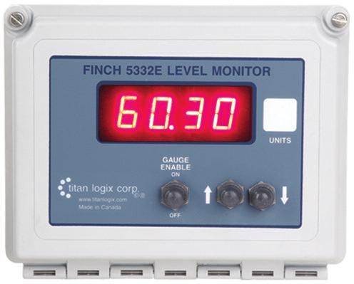
6 2. Finch Display shows OFF when the PTO is engaged or Gauge Enable is on. WHAT TO DO: DETAILS: WHAT TO CHECK: REMEDY: Manually enable the PTO signal with the Gauge Enable switch on the Finch 5332E Display if it is available. If the system activates, then check for an open circuit in the PTO signal as follows: i. Clip the test light to ground and probe tip to the PTO signal at all points in the circuit. The test light will complete a path to ground and activate the PTO signal. Probe all points from the 5332(E) PTO signal input back to the source. This will isolate a broken wire or defective switch. Inspect for broken or corroded wiring where the test light fails to activate the PTO signal and repair as necessary ii. An alternative method is to clip the test light to battery power and confirm the PTO signal is grounded at all circuit points until the light does not illuminate. This will isolate the wire break or defective switch. a. Inspect for broken or corroded wiring where the test light fails to illuminate and repair as necessary b. If the Gauge Enable switch or PTO signal ground at the 5332(E) does not activate the system, then the 5332(E) PTO signal input is defective. Finch Display is faulty, replace the unit Page 74/ TD80 and Overfill Prevention System Troubleshooting/ Rev. 0.1, January 17, 2013
7 3. Loss of SV Bus Communication, Finch Display shows WHAT TO DO: DETAILS: REMEDY: a displayed on the 5332(E) indicates loss of SV Bus communication with the TD80 transmitter. Any other Display such as 2 LO, E 20, Spill or level confirms proper communication with the transmitter. b. If multiple compartments are displayed on one 5332(E), check all compartment positions on the selector switch i. If all positions are inactive, check the wiring from the switch to the SV Bus input on the 5332(E) and common power supply wiring to the TD80 transmitters. ii. If one or more compartments; but not all are inactive, then troubleshoot the Transmitter and wiring to the selector switch. Inspect for broken or corroded wiring and repair as necessary. Inspect for broken or corroded wiring and repair as necessary. c. Check the SV Bus LED on the 5332(E) for activity. Blinking fully on and fully off indicates normal bus voltages. The LED will blink in bursts every second as the level information is transmitted to the Display. i. Partially on or off indicates a defective TD80 system component, loss of power to a TD80 system component or an SV Bus short circuit to either power or ground. a. Use the test light to check for power and ground to the TD80 system components on the SV Bus. Check at the power and ground terminals as well as any intermediate connections such as junction boxes, plugs and sockets. b. SV Bus LED partially on indicates short circuit to power Inspect for broken or corroded wiring where the test light fails to illuminate and repair as necessary. Troubleshoot SV Bus and repair or replace as necessary c. SV Bus LED partially off indicates a short circuit to ground. d. If the SV Bus LED is off continuously Troubleshoot SV Bus and repair or replace as necessary i. Check for power and ground to the TD80 Transmitter ii. Clip the test light to ground and probe the SV Bus signal wire. Tap the probe tip on an SV Bus terminal and the LED will blink with each tap to indicate continuity through the wiring and SV Bus receiver in the 5332(E). Probe at each SV Bus circuit point until the open circuit or defective component is isolated. e. If the SV Bus LED is on continuously, check for a short circuit to ground on the SV Bus. This can be done by disconnecting the devices from the SV Bus, clip the test light to battery power and probe for ground on the SV Bus at each circuit point until the short circuit or defective component is isolated. Rev. 0.1, January 17, 2013/ TD80 and Overfill Prevention System Troubleshooting/ Page 75
8 4. Finch Display shows only a decimal point, no numbers. WHAT TO DO: a. Check the power supply for adequate operating voltage. b. Use a test light or DMM to test terminals for battery voltage and ground in a logical sequence. c. Possibly faulty Finch Display, replace the unit DETAILS: Provide power from a well charged battery or DC power source, 8VDC to 28VDC, steady output. Confirm this voltage using a DMM. Do not use a battery charger. i. Check all terminals from the Finch Display back to the battery ii. Inspect all junction boxes, plugs and sockets for broken wires and corrosion 5. Finch Display shows 8888 or flickers between 8888 and other numbers. WHAT DO TO: DETAILS: a. Check that the system is not powered by a Disconnect from the charger and power battery charger from a well charged battery or DC power source, 8VDC to 28VDC, steady output b. Check power supply wiring for intermittent or corroded connections c. Ensure that the battery voltage is at least Provide power from a well charged battery 8VDC and steady or DC power source, 8VDC to 28VDC, steady output d. Finch Display may be faulty, replace the unit 6. Finch Display restarts at erratic intervals. The digit test begins and then displays a level for some time, then restarts with the digit test. WHAT TO DO: DETAILS: a. Check power supply wiring for intermittent or corroded connections b. Ensure that the battery voltage is at least Provide power from a well charged battery 8VDC and steady or DC power source, 8VDC to 28VDC, steady output c. Finch Display may be faulty, replace the unit Page 76/ TD80 and Overfill Prevention System Troubleshooting/ Rev. 0.1, January 17, 2013
9 7. Fill Alarm remains inactive. WHAT TO DO: DETAILS: WHAT TO CHECK: REMEDY: a. Check Fill alarm setting on 5332(E). Confirm that the 5332(E) is flashing the level to indicate an active alarm. i. Confirm that the PTO signal is active by either a switch operation or permanently enabled through wiring. Activate the PTO signal If the PTO signal does activate, then troubleshoot the PTO signal wiring and ii. If the 5332(E) does not flash at the desired fill level components. Confirm and reset the Fill alarm setting. If this does not fix the problem, then the Finch Display may be faulty, replace the unit. iii. If the Finch Display flashes at the alarm setting then troubleshoot the Fill alarm wiring and components. b. Confirm that the J1 shorting jumper is installed correctly. c. Confirm that the J9 Fill/Fall jumper is installed correctly. d. For Fill alarms energized by a ground from the 5332(E) i. Check for power at the Red light and/or Horn. ii. Clip the test light to a. At the 5332(E) FILL-COM, FILLground and probe all Fill NO or FILL-NC alarm circuit points to activate the Red light b. At any external wiring junctions and/or Horn. Circuit points to confirm are as c. Red light and/or Horn follows: e. For Fill alarms energized by power from the 5332(E) iii. Check for a blown fuse (if installed) and replace as necessary iv. Inspect for broken or corroded wiring and repair as necessary v. Inspect for broken or defective horn or light and repair as necessary i. Check for ground at the Red light and/or Horn ii. Clip the test light to power and probe all Fill alarm circuit points to activate the Red light and/or Horn. Circuit points are as described above. iii. Check for a blown fuse (if installed) and replace as necessary iv. Inspect for broken or corroded wiring and repair as necessary v. Inspect for broken or defective horn or light and repair as necessary Rev. 0.1, January 17, 2013/ TD80 and Overfill Prevention System Troubleshooting/ Page 77
10 8. Fill Alarm continuously active. WHAT TO DO: DETAILS: REMEDY: a. Check Fill alarm setting on 5332(E). Confirm that the 5332(E) is not flashing the level to indicate an active alarm. i. If the 5332(E) is flashing level, confirm and reset the Fill alarm setting. If this does not fix the problem, then the 5332(E) is defective. ii. If the Display is not flashing, then troubleshoot the Fill alarm wiring and components. b. Confirm that the J1 shorting jumper is installed correctly. c. For Fill alarms energized by a ground from the 5332(E) Clip the test light to power and troubleshoot the Fill alarm circuit points for a short circuit to ground. Circuit points to confirm are as follows: 1. At the 5332(E) FILL-COM, FILL-NO or FILL-NC 2. At any external wiring junctions 3. Red light and/or Horn d. For Fill alarms energized by power from the 5332(E) Clip the test light to ground and troubleshoot the Fill alarm circuit points for a short circuit to power. Circuit points are as described above. Page 78/ TD80 and Overfill Prevention System Troubleshooting/ Rev. 0.1, January 17, 2013
11 9. Overfill Prevention System fails to allow loading. WHAT TO DO: DETAILS: WHAT TO CHECK: a. Relay Module i. Ensure that HH and Spill/Fail alarms are inactive, TD80 system is operating normally. ii. Check for a blown HH or SPILL/FAIL fuse (if installed) and replace as necessary iii. Check for power at Relay Module Solenoid terminal 1. If power is present, check wiring and power to solenoid 2. Energize and de-energize solenoid by moving J10 jumper to check for solenoid and valve operation. 3. If no power present at solenoid terminal, check the following: a. Check ground signal through HH and FAIL relays in 5332E Clip test light to ground, probe at 5332E, HH-NC and FAIL-COM (or SPILL/FAIL COM on 5332E/PS Display) to apply ground for loading enable. b. Check ground at Clip test light to HH-NC and FAIL- ground, probe at COM in Relay Relay Box, HH- Module. NC and FAIL- COM to apply ground for loading enable. c. Check J10 shorting jumper is in B position. d. Check PTO signal at Relay Module. Clip test light to ground, probe at Relay Box, PTO to apply ground for loading enable. 4. Inspect for broken or corroded wiring and repair as necessary. b. P2000 i. Ensure that HH and Spill/Fail alarms are inactive, TD80 system is operating normally. ii. Check for a blown HH or SPILL/FAIL fuse and replace as necessary iii. Check J10 shorting jumper is in A position for 5332E/PS (red terminal board Display) or B position for 5332E (green terminal board display). iv. Check that the LED to fiber optic cable is illuminated. v. If the LED is OFF, then troubleshoot the 5332E for HH and FAIL relay fault or open wiring. vi. If the LED is ON, then troubleshoot the fiber optic cable, P2000 and wiring to Scully socket. vii. Inspect for broken or corroded wiring and repair as necessary. Rev. 0.1, January 17, 2013/ TD80 and Overfill Prevention System Troubleshooting/ Page 79
12 10. Overfill Prevention System fails to stop loading on high level alarms. WHAT TO DO: DETAILS: a. Relay Module i. Ensure that HH and Spill/Fail alarms activate, TD80 system is operating normally. ii. Deactivate/reset the alarms for further troubleshooting. iii. Check for power at Relay Module Solenoid 1. If power is present, check wiring to terminal solenoid for a short circuit to power. 2. If power is not present, check solenoid valve. 3. Energize and de-energize solenoid by moving J10 jumper to check for solenoid and valve operation. This also checks for a shorted 5332E FAIL-NC (or SPILL/FAIL-NC on 5332E/PS Display) to FAIL-COM (or SPILL/FAIL-COM on 5332E/PS Display) connection. iv. Check for short circuit to ground at Relay Module HH-NC. v. Check for short circuit to ground at 5332E HH-NC, HH-COM and FAIL-NC (or SPILL/FAIL- NC on 5332E/PS Display). vi. Inspect for defective, incorrect or corroded wiring and repair as necessary b. P2000 i. Ensure that HH and Spill/Fail alarms activate, TD80 system is operating normally. ii. Deactivate/reset the alarms for further troubleshooting. iii. Check that the LED to fiber optic cable is OFF iv. If the LED is OFF, then troubleshoot the P2000 v. If the LED is ON, then troubleshoot the 5332E HH and FAIL relay fault or shorted wiring. vi. Inspect for defective, incorrect or corroded wiring and repair as necessary 11. Overfill Prevention System fails to stop loading when PTO signal is off. WHAT TO DO: DETAILS: a. Relay Module i. Ensure that HH and Spill/Fail alarms activate, TD80 system is operating normally. ii. Deactivate/reset the alarms for further troubleshooting. iii. Energize and de-energize solenoid by moving J10 jumper to check for solenoid and valve operation. iv. Ensure that the 5332E Displays OFF when the PTO signal is disengaged. v. If the 5332E displays level when PTO signal is disengaged, test for short circuit to ground on PTO signal. vi. If the 5332E displays OFF when PTO signal is engaged/on, test for an open circuit between 5332E PTO input and Relay Module PTO terminal. vii. Check for power at Relay Module Solenoid 1. If power is present, check wiring to terminal solenoid for a short circuit to power. 2. If power is not present, check solenoid valve. viii. Inspect for defective, incorrect or corroded wiring and repair as necessary. b. P2000 i. If the 5332E displays level when PTO signal is disengaged, test for short circuit to ground on PTO signal. ii. Energize and de-energize the LED by moving J10 jumper to check for normal operation. iii. Inspect for defective, incorrect or corroded wiring and repair as necessary. Page 80/ TD80 and Overfill Prevention System Troubleshooting/ Rev. 0.1, January 17, 2013
13 12. Finch Display shows an Error Code (E xx) The transmitter constantly checks the system for errors. Detected errors are shown on the Finch Display as an error code, E and a 2 digit number. This error code assists in diagnosing and repairing the problem. E 80 through E 84 indicate an error caused by an incorrect strapping table or internal transmitter malfunction. For these errors, review the programming information, correct if necessary and reprogram the transmitter. If the malfunction persists, then replace the transmitter and ensure it is programmed correctly. The error codes and possible solution are listed below. E 00 Can t Autorange (could not measure level) - possibly bent or damaged probe - move the probe location to a less turbulent area of the tank - possibly defective transmitter E 01 Too many samples rejected (too much turbulence) - move the probe to a less turbulent area of the tank - possibly defective transmitter - defective transmitter E 02 Internal transmitter error, Wrap around on Timer1 E 04 Internal transmitter error, Timer1 - defective transmitter count is too large E 10 Internal transmitter error, timeout - defective transmitter between captures E 20 No fiducial detected - possibly defective transmitter - possibly damaged or defective probe - possible turbulence in the tank - possible disconnection of transmitter and probe - possible liquid or grease contamination of transmitter to probe connection E 40 E 80 E 81 Internal transmitter error, Watchdog reset Internal strapping table error, HH alarm level set too close to Spill alarm level Internal strapping table error, Alarms set, No strapping table - defective transmitter - incorrect strapping table, reprogram the transmitter with a correct table - program the transmitter with a strapping table - possibly defective transmitter E 82 Internal strapping table error - reprogram the transmitter - possibly defective transmitter E 83 Internal strapping table error, error detected in strapping table during operation - restart the transmitter, if problem persists then reprogram the transmitter - possibly defective transmitter E 84 Internal strapping table error, error detected in strapping table during operation - restart the transmitter, if problem persists then reprogram the transmitter - possibly defective transmitter Error codes 01, 02, 04, 10, 20 and 40 can be combined if there is more than one error code at a time, for example E 26 is E 02 + E 04 + E 20. E 80 to E 84 will not be combined with any other error codes. Rev. 0.1, January 17, 2013/ TD80 and Overfill Prevention System Troubleshooting/ Page 81
14 13. Finch Display continuously shows 2 LO. WHAT TO DO: DETAILS: REMEDY: a. Check the probe for physical i. Probe may be faulty. Replace the probe. damage, defects, corrosion or product build up. ii. Probe may be bent or twisted. Repair or replace the probe. iii. Inspect the probe for product buildup. Clean the probe with a solvent compatible with b. The TD80 transmitter may be defective. c. Check the probe to TD80 transmitter connection for contamination. d. Check installation of the coaxial probe if installed the product. Replace the TD80 transmitter with a serviceable unit that has been programmed with same information as the one it is replacing. Clean out any contamination such as water, oil, grease or dirt. The connectors must be clean and make a solid mechanical connection. Retighten the connectors and test the system. The transmitter must be securely fastened to the probe Hand tighten the transmitter nut until it is at the o-ring, then fully tighten with a wrench. 14. Finch Display shows erratic level measurements or 2 LO. WHAT TO DO: DETAILS: REMEDY: a. Finch Display shows erratic level measurements while a mobile radio is keyed or other radio equipment transmits. b. Finch Display shows erratic level measurements or 2 LO while loading or unloading product. c. Check installation of the coaxial probe if installed Physically separate all TD80 system components and wiring from the radio devices. i. Check the probe for physical damage, defects, corrosion or product build up. ii. The TD80 transmitter may be defective. iii. Check the probe to TD80 transmitter connection for contamination. The transmitter must be securely fastened to the probe 1. Probe may be faulty, replace the probe. 2. Probe may be bent or twisted, repair or replace the probe. 3. Probe may be corroded, replace the probe. 4. The shorting block may be loose or missing, repair or replace the shorting block. 5. Inspect the probe for product buildup. Clean the probe with a solvent compatible with the product. Replace the TD80 transmitter with a serviceable unit that has been programmed with same information as the one it is replacing. Clean out any contamination such as water, oil, grease or dirt. The connectors must be clean and make a solid mechanical connection. Retighten the connectors and test the system. Hand tighten the transmitter nut until it is at the o-ring, then fully tighten with a wrench. Page 82/ TD80 and Overfill Prevention System Troubleshooting/ Rev. 0.1, January 17, 2013
15 15. Spill alarm is on continuously, unable to clear the alarm by unloading while the TD80 is turned on or by entering Calibration mode. WHAT TO DO: DETAILS: REMEDY: a. Check installation of the dual rod probe if installed. b. Check installation of the coaxial probe if installed. c. Check probe for buildup of product at or near the top of the probe. i. The tank mounting collar or fitting must not extend more than 1.5 below the 1 3/4 nut on the probe. ii. A 4 minimum diameter around the probe must be free of any metal objects. iii. The transmitter must be securely fastened to the probe Inspect the inside of the probe near the top for any metal foreign objects. Clean the probe with a solvent compatible with the product The mounting fitting height must be reduced to 1.5 or less. The probe must be relocated to an area that has at least 4 diameter around it free from metal objects. Hand tighten the transmitter nut until it is at the o-ring, then fully tighten with a wrench. Shake or flush out any foreign objects inside the coaxial probe. The probe may require removal for thorough inspection and cleaning 16. Unable to offset calibrate the TD80. WHAT TO DO: DETAILS: REMEDY: a. Finch Display shows 2 LO after flashing CAL. b. Finch Display continues to flash CAL without showing current volume. c. Finch Display shows a level after flashing CAL, unable to set the Display to the actual volume. i. The tank may be empty or the level is less than 5 ½ from the bottom of the tank. Fill the tank above 5 ½ and Calibrate. i. Possibly defective Replace Finch Display Finch Display ii. possibly defective Replace TD80 transmitter TD80 transmitter iii. TD80 transmitter power may be independent from the Finch Display power. Power must be cycled to the Finch Display and TD80 at the same time for offset calibration. i. The TD80 transmitter may be defective. ii. The TD80 transmitter may be incorrectly programmed. iii. Finch Display button presses do not change the setting in one or both directions Replace the TD80 transmitter with a serviceable unit that has been programmed with same information as the one it is replacing. Reprogram the transmitter with correct information. Inspect the push button wiring inside Finch Display for a loose or removed connector(s) Reinstall push button connector(s) if disconnected or replace the defective Finch Display. Rev. 0.1, January 17, 2013/ TD80 and Overfill Prevention System Troubleshooting/ Page 83
16 3.2.2 Common Installation Wiring and Component Problems The following troubleshooting steps are organized by problems commonly experienced after installation. They may be encountered after a new installation, retrofit or repair of an in-service vehicle. These are some of the most common frequent system wiring and component installation errors along with suggested troubleshooting and repair steps. The problems may also be the result of a normal breakdown or component malfunction. 1. Unable to offset calibrate the TD80. WHAT TO DO: DETAILS: REMEDY: a. Finch Display shows 2 LO after flashing CAL. The tank may be empty or the level is less than 5 ½ from the bottom of the Fill the tank above 5 ½ and Calibrate. b. Finch Display continues to flash CAL without showing current volume. c. Finch Display shows a level after flashing CAL, unable to set the Display to the actual volume. tank. i. Possibly defective Finch Display ii. possibly defective TD80 transmitter iii. TD80 transmitter power may be independent from the Finch Display power. Power must be cycled to the Finch and TD80 at the same time for offset calibration. i. The TD80 transmitter may be defective. ii. Finch Display button presses allow changes in both directions, halts when lowering the actual volume before the calibrated volume is reached iii. Finch Display button presses do not change the setting in one or both directions Replace Finch Display Replace TD80 transmitter Possibly incorrect power wiring to the Finch Display and TD80 transmitter. Replace the TD80 transmitter with a serviceable unit that has been programmed with same information as the one it is replacing. The TD80 transmitter is incorrectly programmed. Inspect the push button wiring inside Finch Display for a loose or removed connector(s) Reprogram the transmitter with correct information. Reinstall push button connector(s) if disconnected or replace the defective Finch Display. Page 84/ TD80 and Overfill Prevention System Troubleshooting/ Rev. 0.1, January 17, 2013
17 2. Fuses keep blowing WHAT TO DO: DETAILS: REMEDY: a. Verify that the type and rating Install fuse with the correct type and rating. of the fuse is appropriate for the application b. Verify that the system i. Inspect all wiring for installation errors. components are installed and wired correctly. ii. Continue by disconnecting power to system components to isolate the short circuit. Clip on battery power; probe each component at the power terminal. A short circuit to ground is indicated by the light fully illuminating. Repair or replace the defective component as necessary 3. Spill alarm stuck on. WHAT TO DO: DETAILS: REMEDY: a. Check installation of the dual rod probe if installed. b. Check installation of the coaxial probe if installed. i. The tank mounting collar or fitting must not extend more that 1.5 below the 1 3/4 nut on the probe. ii. A 4 minimum diameter around the probe must be free of any metal objects. iii. The transmitter must be securely fastened to the probe Inspect the inside of the probe near the top for any metal foreign objects. The mounting fitting height must be reduced to 1.5 or less. The probe must be relocated to an area that has at least 4 diameter around it free from metal objects. Hand tighten the transmitter nut until it is at the o-ring, then fully tighten with a wrench. Shake or flush out any foreign objects inside the coaxial probe. 4. Finch Display continuously shows 2 LO. WHAT TO DO: Check installation of the coaxial probe if installed DETAILS: The transmitter must be securely fastened to the probe Hand tighten the transmitter nut until it is at the o-ring, then fully tighten with a wrench. Rev. 0.1, January 17, 2013/ TD80 and Overfill Prevention System Troubleshooting/ Page 85
18 5. Finch Display continuously shows a level in an empty tank. WHAT TO DO: DETAILS: REMEDY: a. Check the probe for physical damage, defects or product build up. i. Probe may be bent or twisted Repair or replace the probe. b. The TD80 transmitter may be defective. c. The TD80 transmitter may be incorrectly programmed. ii. Inspect the probe for heavy product buildup bridging the rods. Clean the probe with a solvent compatible with the product. Replace the TD80 transmitter with a serviceable unit that has been programmed with same information as the one it is replacing. Reprogram the transmitter with correct information. 6. Finch Display shows incorrect volume. WHAT TO DO: DETAILS: a. The TD80 transmitter may be defective. Replace the TD80 transmitter with a serviceable unit that has been programmed with same information as the one it is replacing. b. The TD80 transmitter may be incorrectly Reprogram the transmitter with correct programmed. information. c. Offset calibration may be required. Perform the offset calibration. 7. Finch Display continuously shows OFF until a Display push button is pressed. WHAT TO DO: DETAILS: a. Verify that the PTO signal is wired according i. Inspect the wiring for correct installation to the installation diagram ii. Inspect for loose or broken wiring iii. Correct all wiring errors and continue to b. Test the PTO or air brake controlled switch for correct operation 8. Finch Display shows erratic level measurements. verify system operation. Repair or replace the switch as necessary. WHAT TO DO: DETAILS: REMEDY: a. Finch Display shows erratic level measurements while a Physically separate all TD80 system components and wiring from the radio devices. mobile radio is keyed or other radio equipment transmits b. Finch Display shows erratic level measurements or 2 LO while loading product. Check placement of the probe near inlet or agitator The probe must be relocated to an area of the tank away from turbulence while loading or normal operation. Page 86/ TD80 and Overfill Prevention System Troubleshooting/ Rev. 0.1, January 17, 2013
19 9. Relay Module Shutdown system does not permit loading. WHAT TO DO: DETAILS: REMEDY: a. Check the position of the Finch Display J10 jumper. This Verify jumper J10- B position, place in B position if necessary jumper is located internally on the Display circuit board. b. Check for a blown HH or SPILL/FAIL fuse and replace as necessary c. Check installation of wiring Confirm wire is installed for inside Finch Display the following 1. Finch 5332E/PS, red terminal board, wire between SPILL/FAIL OUTPUT (20) and HH-COM (17) 2. Finch 5332E, green terminal board, wire between Fail-NC and HH-COM 10. P2000 Shutdown system does not permit loading. WHAT TO DO: DETAILS: a. Check the position of the Finch Display J10 Verify jumper J10- A position, place in A jumper. This jumper is located internally on the position if necessary Display circuit board. b. Check for a blown HH or SPILL/FAIL fuse and replace as necessary c. Check installation of wiring inside Finch Display d. Check installation of optical cable inside Finch Display 11. Fill alarm horn continuously sounds when power is turned on. WHAT TO DO: a. Check the position of the Finch Display J1 jumper. This jumper is located internally on the Display circuit board. DETAILS: i. FILL-NC contact controlling the horn, J1- A position ii. FILL-NO contact controlling the horn, J1- B position b. Check for wiring shorts to power or ground Correct all wiring errors and continue to verify system operation. c. Check the Fill alarm level The Fill alarm may be incorrectly set too low. Confirm and enter the correct alarm setting. Rev. 0.1, January 17, 2013/ TD80 and Overfill Prevention System Troubleshooting/ Page 87
20 3.3 Alternate TD80 System Troubleshooting Sometimes it is easier and less complicated to isolate a system problem by disconnecting all the components and then rewiring them back in a logical sequence. This method is described below. Checked Step Description 1. Ensure that the power is off and disconnect all external wiring to the Finch Display. 2. Connect the two wires providing power and ground. 3. Turn on the power and verify that the Finch Display powers up normally, then displays It may then display OFF or continue to display ---- if the PTO is permanently wired to ground or the gauge enable switch is on. Resolve all problems at this point before continuing. 4. Turn the power off. 5. Install the PTO wiring if applicable. Turn power on, verify that the Finch displays ---- continuously with the PTO signal active, then OFF with the PTO inactive. Resolve all problems at this point before continuing. 6. Turn power off. 7. Install the three wires from the TD80 transmitter to the Finch Display. Turn power on, verify that the Finch displays something other than If it displays OFF, press a button and verify that something other than ---- is displayed. Resolve all problems at this point before continuing. 8. Turn power off. At this point, the TD80 system is functioning and reporting level, an alarm condition or an error code. 9. Resolve all problems until the TD80 is functioning normally with a level display and inactive alarms. 10. Turn power off. 11. Continue to wire accessory components one at a time and verify correct system operation. Ensure power is off before connecting or disconnecting any wiring. 3.4 TD80 System Tests The following tests are used to determine correct operation of optional alarm accessories such as horns, lights and overfill prevention system. They do not verify correct operation of the TD80 level transmitter, probe or display. The purpose is to exercise the optional components for troubleshooting or repair tests. 1. Fill Alarm Test 1. Verify normal TD80 system operation. Resolve all problems at this point before continuing. 2. Turn on power to the TD80 system. 3. Ensure all alarms are inactive and reset as necessary. Page 88/ TD80 and Overfill Prevention System Troubleshooting/ Rev. 0.1, January 17, 2013
21 4. Change J1 jumper to the opposite position and verify that the Fill alarm horn sounds and if installed, the light illuminates. 5. Place the J1 jumper back to the original position and verify that the Fill alarm horn silences and if installed, the light goes out. 2. Finch Relay Module Shutdown System Test 1. Verify normal TD80 system operation. Resolve all problems at this point before continuing. 2. Turn on power and activate the PTO signal. 3. Ensure all alarms are inactive and reset as necessary. 4. Confirm J10 jumper is in B position. Change from B to A position and verify that the solenoid or voltage to the solenoid changes with the jumper position. a. Voltage to the solenoid and loading enabled in B position. b. No voltage to the solenoid and loading disabled in A position. c. Confirm normal operation or resolve all problems at this point before continuing. 5. Activate each alarm in turn and verify normal shutdown operation. Resolve all problems before continuing. 6. Test all system functions and verify correct operation. 3. P2000 Optic Shutdown System Test 1. Verify normal TD80 system operation. Resolve all problems at this point before continuing. 2. Turn power on and activate the PTO signal. 3. Ensure all alarms are inactive and reset as necessary. 4. Confirm Finch 5332E/PS Display J10 jumper is in correct position ( A ) and verify that the fiber optic LED changes with the jumper position. a. Fiber optic LED on and loading enabled in A position. b. Fiber optic LED off and loading disabled in B position. c. Confirm normal operation or resolve all problems at this point before continuing. i. The fiber optic LED will be illuminated in a normal or non-alarming condition. ii. The fiber optic LED will be off in any Spill, HH or Error alarming condition. iii. Ensure that the wire jumpers at Spill/Fail and HH alarm relays are wired correctly. iv. Check Finch Display terminal board fuses F1 power, F5 Spill and F4 H.H. 5. Test at Scully optic socket with the Universal Truck Tester (UTT). This unit provides all signals and monitors response identically to the Scully Optic Rack. Resolve all problems at this point before continuing. Check for corroded or broken wiring between the Scully Optic socket and the P2000. Visually inspect the fiber optic cable. Isolate each P2000 if installed on a multi-compartment truck/trailer and test separately. 6. Test all system functions and verify correct operation. The following diagrams and schematics are for reference during troubleshooting techniques and are the same as previously shown in section 2: TD80 Installation. Rev. 0.1, January 17, 2013/ TD80 and Overfill Prevention System Troubleshooting/ Page 89
22 Figure 3-1: Basic System Wiring Schematic for Finch 5332E/PS External Display Page 90/ TD80 and Overfill Prevention System Troubleshooting/ Rev. 0.1, January 17, 2013
23 Figure 3-2: Basic System Wiring Schematic for Finch 5332E External Display Rev. 0.1, January 17, 2013/ TD80 and Overfill Prevention System Troubleshooting/ Page 91
24 Figure 3-3: Basic System Wiring Diagram for Finch 5332 Internal Display Page 92/ TD80 and Overfill Prevention System Troubleshooting/ Rev. 0.1, January 17, 2013
25 Figure 3-4: Single P2000 Overfill Prevention System Wiring Schematic Rev. 0.1, January 17, 2013/ TD80 and Overfill Prevention System Troubleshooting/ Page 93
26 Figure 3-5: Finch Relay Module Overfill Prevention System Wiring Schematic for Finch 5332E with Horns and Lights Page 94/ TD80 and Overfill Prevention System Troubleshooting/ Rev. 0.1, January 17, 2013
27 Figure 3-6: Basic Shutdown Wiring for Finch 5332E/PS External Display Rev. 0.1, January 17, 2013/ TD80 and Overfill Prevention System Troubleshooting/ Page 95
28 Figure 3-7: Finch Relay Module Overfill Prevention System for Finch 5332E/PS with Horns and Lights Page 96/ TD80 and Overfill Prevention System Troubleshooting/ Rev. 0.1, January 17, 2013
29 Figure 3-8: Basic Shutdown Wiring Schematic for Finch 5332E External Display Rev. 0.1, January 17, 2013/ TD80 and Overfill Prevention System Troubleshooting/ Page 97
30
31 Manufactured in Canada Manufactured by: Head Office Street Edmonton, Alberta Canada T6E 5P5 P F Saskatchewan Branch Box Cenaiko Street Lampman, Saskatchewan Canada S0C 1N0 P F Kansas Branch 8900 Nieman Road Overland Park, Kansas USA P F Toll Free TSX-V: TLA Sales Department: us at sales@titanlogix.com Service Department: us at service@titanlogix.com Find us online at
1998 E-Series Workshop Manual
 SECTION 206-09A: Anti-Lock Control Rear DIAGNOSIS AND TESTING Procedure revision date: 02/08/2000 Anti-Lock Control Refer to Wiring Diagrams Cell 42, Speed Control for schematic and connector information.
UNIT 3: GENErAL ELECTriCAL SySTEM DiAGNOSiS
 Electrical/Electronic Systems UNIT 3: GENErAL ELECTriCAL SySTEM DiAGNOSiS LESSON 3: TEST electrical circuits I. Types of electrical circuit tests and electrical faults A. Different types of electrical
BOLT-ON AND WELD-ON FLUSH FLOOR SLIDEOUT SYSTEMS OPERATION AND SERVICE MANUAL
 BOLT-ON AND WELD-ON FLUSH FLOOR SLIDEOUT SYSTEMS OPERATION AND SERVICE MANUAL TABLE OF CONTENTS SYSTEM...... Warning........ Description...... Prior to Operation OPERATION... Main Components... Mechanical...
Sofa Slideout Assembly OWNER'S MANUAL. Rev: Page 1 Sofa Slideout Owners Manual
 Sofa Slideout Assembly OWNER'S MANUAL Rev: 06.14.2016 Page 1 Sofa Slideout Owners Manual TABLE OF CONTENTS Warning, Safety, and System Requirement Information 3 Product Information 3 Prior to Operation
R & D SPECIALTIES ROTROL I USER'S MANUAL
 R & D SPECIALTIES ROTROL I USER'S MANUAL TABLE OF CONTENTS INTRODUCTION...2 SPECIFICATIONS...2 CONTROLS AND INDICATORS...3 TIME DELAYS...4 INSTALLATION...5 SYSTEM OPERATION...9 TROUBLESHOOTING...13 OPTIONAL
Embedded Rack Slide-out System
 Embedded Rack Slide-out System SERVICE MANUAL Rev: 02.16.2017 Page 1 Electric Embedded Rack Slide-out System TABLE OF CONTENTS Safety Information 3 Product Information 3 Operation 4 Extending Slide-Out
Power Distribution System User s Manual. Model: PDS-100
 Power Distribution System User s Manual Model: PDS-0 Section Page Product Overview... 1 I) General Information... 2 II) Important Safety Information... 2 III) Installation... 3 A) Materials Provided...
User Manual. T6 Tachometer. Online: Telephone: P.O. Box St. Petersburg, Florida 33736
 User Manual T6 Tachometer Online: www.phareselectronics.com Telephone: 727-623-0894 P.O. Box 67251 St. Petersburg, Florida 33736 Table of Contents Overview... 1 Description... 1 Wiring... 1 T6 Tachometer
Page 1 of 1 ALTERNATORS. Overview. Intek TM V-Twin Cylinder OHV Engine Service Manual Version 1.0. Copyright 1999 by Briggs and Stratton Corporation
 Overview Alternator Identification Page 1 of 3 The alternator systems installed on Briggs & Stratton Intek V-Twin Cylinder OHV Engines can easily be identified by the color of the stator output wires and
Subject Underhood G System Error Codes and Symptoms System or Parts affected
 System or Parts affected Index Underhood70G (V90Gxxx) System or Parts affected... 1 Overview... 1 Identifying your System... 1 Retrieving Logged Error Messages... 1 Error Messages... 3 Error Message Table...
D3000. Troubleshooting Guide
 Page 1 of 6 17486-00 Rev B s3 April 2009 Contents Description Page Safety.. 3 Introduction 3 Standard External Controls, Indicators and Normal Alarm Conditions 3 Troubleshooting Table.. 4 Unable to program
PowerLevel s e r i e s
 Owner s Manual Hydraulic Leveling CONTENTS Introduction Operation Control Panel Automatic Leveling Manual Leveling Retracting Jacks Remote Operation Care & Maintenance Troubleshooting Error Codes 1 2 2
California Friendly Landscape Training
 California Friendly Landscape Training Irrigation Course Irrigation System Troubleshooting Course originally developed by California Polytechnic State University, San Luis Obispo Irrigation Training &
LIPPERTCOMPONENTS, INC.
 LIPPERTCOMPONENTS, INC. SCHWINTEK INWALL SLIDEOUT SYSTEM OPERATION AND SERVICE MANUAL Contents I. Controls 1-1 System components 1 1-1A versions C1 & C2 2 1-2 Motor wiring harness connections 3 1-3 Extend
Thunder Power Tarp Kit Operation
 Thunder Power Tarp Kit Operation Dual Arm Curb Side Stowing Single Arm Curb Side Stowing 011-52476 Rev. H P a g e 2 In this booklet you will find: OPERATING INSTRUCTIONS... 3 Powering up or down the system...
Thunder Power Tarp Kit Operation. Dual Arm Curb Side Stowing Single Arm Curb Side Stowing Flex Arm Curb Side Stowing.
 Thunder Power Tarp Kit Operation Dual Arm Curb Side Stowing Single Arm Curb Side Stowing Flex Arm Curb Side Stowing 011-52475 Rev - 2 P a g e USE THE PROCEDURES BELOW TO OPERATE THE TARP SYSTEM Powering
STANDARD AND GROUND SWITCHED APPLICATIONS
 SNOWDOGG LIGHT REFERENCE STANDARD AND GROUND SWITCHED APPLICATIONS GENERAL REFERENCE SNOWDOGG LIGHT REFERENCE GENERAL REFERENCE 3 TROUBLESHOOTING GUIDES/PROCEDURES 6 CONNECTOR REFERENCE 12 ADAPTER HARNESS
 YNCHRONIZER AUTOMATIC SYNCHRONIZE TROUBLESHOOTING GUIDE SOLENOID (MODEL 1750) RELAY ASSEMBLY LIMIT SWITCH ENGINE CABLE CABLE TO ENGINE THROTTLE RED COLLAR ADJUST LIMIT SWITCH OPERATION BRIDGE CABLE CONTROL
TPM Fuse Panel Installation Guide. Document INS-727XXXXXXX This manual covers the following part numbers- Trimm 727XXXXXXX Family
 TPM Fuse Panel Installation Guide Document INS-727XXXXXXX This manual covers the following part numbers- Trimm 727XXXXXXX Family Table of Contents Section 1- General Information... 3 1.1 - Product Description...
Manufacturing & Service: Bierer & Associates Inc. Patent No. 6,885,180. ST Series Service Tester Phase Identifier Operating Instructions ST500PGN
 Manufacturing & Service: Bierer & Associates Inc. Patent No. 6,885,180 ST Series Service Tester Phase Identifier Operating Instructions ST500PGN REV. ED. 101229 CONTENTS Limitation of Warranty and Liability
TPM/GMT Panel Installation Guide
 TPM/GMT Panel Installation Guide Document INS-837xxxxxxx This manual covers the following part numbers- Trimm 837xxxxxxx Family Table of Contents Table of Contents... 2 Section 1- General Information...
HOW - TO WIRING & LIGHTING
 HOW - TO WIRING & LIGHTING Tool And Material Checklist Test Light Service Manual Penetrating Oil Long-Nose Pliers T-Square or Right Angle Screwdriver Black Electrical Tape Fuses Fuse Puller Cloth or Paper
Operating Manual OBD Link Connector
 Operating Manual OBD Link Connector OBD Link Connector (OLC) provides the following functions when it is plugged into the car or truck Diagnostic Link Connector (DLC) port: 1. TEST OBD2 PORT BEFORE PLUG
User s Manual. Automatic Switch-Mode Battery Charger
 User s Manual Automatic Switch-Mode Battery Charger IMPORTANT Read, understand, and follow these safety rules and operating instructions before using this battery charger. Only authorized and trained service
Table No. 1 provides a means of identifying the various alternator systems. Note: All output figures are rated at 3600 RPM. TABLE NO.
 The alternator systems installed on Briggs & Stratton Intek OHV-Twin Cylinder Engines can easily be identified by the color of the stator output wires and the connector. Table No. 1 provides a means of
2001 Dodge Durango ACCESSORIES & EQUIPMENT' 'Anti-Theft Systems - Dakota & Durango 2001 ACCESSORIES & EQUIPMENT
 DESCRIPTION VEHICLE THEFT SECURITY SYSTEM 2001 ACCESSORIES & EQUIPMENT Anti-Theft Systems - Dakota & Durango Vehicle Theft Security System (VTSS) provides perimeter protection against unauthorized use
MULTIRACK. Optic / Thermistor Rack Control for Trucks MODEL 688S / 688D MANUAL. Printed in Canada
 MULTIRACK TM Optic / Thermistor Rack Control for Trucks MODEL 688S / 688D MANUAL Printed in Canada www.garnetinstruments.com GARNET MultiRACK TM Optic / Thermistor Rack Control for Trucks MODEL 688S/688D
GENERAL <ELECTRICAL>
 00E-1 GROUP 00E GENERAL CONTENTS HARNESS CONNECTOR INSPECTION................... 00E-2............. 00E-6................. 00E-6 TROUBLESHOOTING STEPS.......... 00E-6 INFORMATION FOR DIAGNOSIS.......
GENERAL <ELECTRICAL>
 00E-1 GROUP 00E GENERAL CONTENTS HARNESS CONNECTOR INSPECTION................................. 00E-2............. 00E-6................. 00E-6 TROUBLESHOOTING STEPS.......... 00E-6 INFORMATION
Spray Height Controller
 Spray Height Controller UC5 SERVICE MANUAL 2012 Printed in Canada Copyright 2012 by NORAC Systems International Inc. Reorder P/N: UC5 SERVICE MANUAL 2012 Rev B NOTICE: NORAC Systems International Inc.
The function of this Dynamic Active Probe has divided into three preferences on the screen main Menus:
 1.0 Introduction: This probe is designed to provide an additional help to automotive technicians in trouble shooting of electrical circuits problems in the car. Apart from using the normal multi tester,
P-600. Technical Manual. Troubleshooting Repairs Replacements
 P-600 Technical Manual Troubleshooting Repairs Replacements Table of Contents P-600 Lift Symptoms and Problems Finding the Problem Before Getting Inside 3 Pneumatic Systems 4 Electrical Systems 5 Mechanical
Installation Instructions
 patent pending Portable Proportional Braking System Installation Instructions Part number 9400 Towing and Suspension Solutions ROADMASTER, Inc. 6110 NE 127th Ave. Vancouver, WA 98682 800-669-9690 Fax 360-735-9300
Service and Parts Manual. NO LONGER IN PRODUCTION Some service parts may not be available for this product. Otolaryngology Chair.
 thru 391-001 -002 Otolaryngology Chair Serial Number Prefixes: EN, PD & V Service and Parts Manual NO LONGER IN PRODUCTION Some service parts may not be available for this product. 391-001 thru -002 NOTE:
BASIC BRAKE SYSTEM GROUP 35A 35A-1 CONTENTS GENERAL DESCRIPTION... 35A-3 BASIC BRAKE SYSTEM DIAGNOSIS 35A-6
 35A-1 GROUP 35A BASIC BRAKE SYSTEM CONTENTS GENERAL DESCRIPTION......... 35A-3 DIAGNOSIS 35A-6 INTRODUCTION..................... 35A-6 DIAGNOSTIC TROUBLESHOOTING STRATEGY......................... 35A-6
OnCommand Troubleshooting Guide Hayward Industries
 OnCommand Troubleshooting Guide 2010 Hayward Industries Table of Contents Safety Precautions Page 1 Overview Pages 2-5 Software Troubleshooting Page 6 Local Display Pages 7-8 Relays Pages 9-10 Heaters
SYNCHRONIZE YNCHRONIZER AUTOMATIC TIC TROUBLESHOOTING GUIDE RELAY ASSEMBLY SOLENOID (MODEL 1750) LIMIT SWITCH ENGINE CABLE CABLE TO
 LIMIT SWITCH ENGINE CABLE CABLE TO") YNCHRONIZER SYNCHRONIZE AUTOMATIC TIC TROUBLESHOOTING GUIDE SOLENOID (MODEL 1750) RELAY ASSEMBLY LIMIT SWITCH ENGINE CABLE CABLE TO ENGINE THROTTLE RED COLLAR ADJUST LIMIT SWITCH OPERATION BRIDGE CABLE
YNCHRONIZER SYNCHRONIZE AUTOMATIC TIC TROUBLESHOOTING GUIDE SOLENOID (MODEL 1750) RELAY ASSEMBLY LIMIT SWITCH ENGINE CABLE CABLE TO ENGINE THROTTLE RED COLLAR ADJUST LIMIT SWITCH OPERATION BRIDGE CABLE
LC I LIPPERT COMPONENTS HYDRAULIC FULL WALL SLIDEOUT SYSTEM OPERATION AND SERVICE MANUAL
 LC I LIPPERT COMPONENTS HYDRAULIC FULL WALL SLIDEOUT SYSTEM OPERATION AND SERVICE MANUAL TABLE OF CONTENTS SYSTEM...... 3 Warning...... 3 Description..... 3 Prior to Operation... 4 4 OPERATION... Main
SPILLSTOP ULTRA Alarm Controller with Hose Protection Overfill Prevention System
 SPILLSTOP ULTRA Alarm Controller with Hose Protection Overfill Prevention System TM MODEL 815-UHP PTO VERSION MANUAL Printed in Canada www.garnetinstruments.com GARNET SPILLSTOP ULTRA TM Hose Protection
INSPECTOR LINE LOAD SIMULATOR INSTRUCTION MANUAL TASCO, INC.
 INSPECTOR LINE LOAD SIMULATOR INSTRUCTION MANUAL INS120P TASCO, INC. THIS TESTER IS DESIGNED FOR USE ONLY BY QUALIFIED ELECTRICIANS. IMPORTANT SAFETY WARNINGS mwarning Read and understand this material
WARNING. Murphy W-Series Engine Panels General Installation Instructions. Installation Accessories
 Murphy W-Series Engine Panels General Installation Instructions WS-93002N Revised 04-06 Section 30 (00-02-0191) Read the following information before installing. These installation instructions are typical
ONE TOUCH CONTROL BOX
 ONE TOUCH CONTROL BOX CONVERSION KIT INSTRUCTIONS REMOVAL, INSTALLATION, OPERATION, AND REMOTE CONTROL PROGRAMMING THUNDERSTONE PART #101322 REVISION A JULY 14 TH 2016 2 P a g e INSTALLING THE THUNDER
3 Phase Smart Controller
 3 Phase Smart Controller Installation and Owner s Manual STP-SCIII 208-230 VAC, 60Hz, 120 Volt Coil Franklin Fueling 3760 Marsh Rd. Madison WI 53718 USA Tel: +1 608 838 8786 800 225 9787 Fax: +1 608 838
WARNING. Murphy W-Series Engine Panels General Installation Instructions. Installation Accessories
 Murphy W-Series Engine Panels General Installation Instructions WS-93002N Revised 08-02 Section 30 (00-02-0191) Read the following information before installing. These installation instructions are typical
Installation & Service Manual
 Installation & Service Manual for M² Sync Slideout Control Box #1510000122 CONTENTS Introduction Installation Installation Problems Program Mode Operation Mode Preventative Maintenance Fault Diagnostics
PF3100 TROUBLESHOOTING SOLUTIONS TO COMMON PROBLEMS. v1.1 Revised Nov 29, 2016
 PF3100 TROUBLESHOOTING SOLUTIONS TO COMMON PROBLEMS v1.1 Revised Table of Contents 1 Common Alarms and Warnings... 1 2 Common Issues... 6 2.1 Communication problems... 6 2.1.1 Controller communication
GROUP 35A 35A-1 CONTENTS GENERAL DESCRIPTION... 35A-3 BASIC BRAKE SYSTEM DIAGNOSIS 35A-6 HYDRAULIC BRAKE BOOSTER (HBB) DIAGNOSIS...
 DIAGNOSIS...") 35A-1 GROUP 35A CONTENTS GENERAL DESCRIPTION......... 35A-3 DIAGNOSIS 35A-6 INTRODUCTION..................... 35A-6 DIAGNOSTIC TROUBLESHOOTING STRATEGY......................... 35A-6 SYMPTOM CHART...................
35A-1 GROUP 35A CONTENTS GENERAL DESCRIPTION......... 35A-3 DIAGNOSIS 35A-6 INTRODUCTION..................... 35A-6 DIAGNOSTIC TROUBLESHOOTING STRATEGY......................... 35A-6 SYMPTOM CHART...................
SCHEMATIC AND ROUTING DIAGRAMS
 2004 ACCESSORIES & EQUIPMENT Theft Deterrent - Corvette SCHEMATIC AND ROUTING DIAGRAMS THEFT DETERRENT SYSTEM SCHEMATICS Fig. 1: Theft Deterrent Relay, Security Indicator, Lighting and Horn References
DIAGNOSTIC TROUBLESHOOTING INDEX
 DIAGNOSTIC TROUBLESHOOTING INDEX Curtis Industries, LLC. 111 Higgins Street Worcester, MA 01606 Telephone: (508) 853-2200 Fax: (800) 876-9104 www.snoproplows.com TROUBLESHOOTING INDEX - BY PROBLEM Section
ECU-02 Ver2.1 Automatic Engine Control Unit Operators Manual
 ECU-02 Ver2.1 Automatic Engine Control Unit Operators Manual Headquarters : No.3, Lane 201, Chien Fu St., Chyan Jenn Dist., Kaohsiung, TAIWAN Tel : + 886-7-8121771 Fax : + 886-7-8121775 URL : http://www.kutai.com.tw
2007 Chevrolet Corvette STEERING Steering Wheel and Column - Corvette. Steering Wheel and Column - Corvette
 2007 STEERING Steering Wheel and Column - Corvette SPECIFICATIONS FASTENER TIGHTENING SPECIFICATIONS Fastener Tightening Specifications Specification Application Metric English Actuator Retaining Screws
WEBER CARBURETOR TROUBLESHOOTING GUIDE
 This guide is to help pinpoint problems by diagnosing engine symptoms associated with specific vehicle operating conditions. The chart will guide you step by step to help correct these problems. For successful
Power Sliding Door (PSD) Diagnostic Approach. Fixing Intermittent Malfunctions. Power Sliding Door (PSD) Diagnostic Information
 Diagnostic Approach. Fixing Intermittent Malfunctions. Power Sliding Door (PSD) Diagnostic Information") Power Sliding Door (PSD) Diagnostic Information Power Sliding Door (PSD) The power sliding door (PSD) provides built-in diagnostics. This assists the service technicians during troubleshooting. The PSD
Power Sliding Door (PSD) Diagnostic Information Power Sliding Door (PSD) The power sliding door (PSD) provides built-in diagnostics. This assists the service technicians during troubleshooting. The PSD
Hydro-Sync Slide-Out System
 Hydro-Sync Slide-Out System SERVICE MANUAL Rev: 08.14.2018 Hydro-Sync Slide-out System Service Manual TABLE OF CONTENTS Safety Information 3 Product Information 3 Operation 4 Extending Slide-Out Room 4
P0441-EVAP PURGE SYSTEM PERFO... P0441-EVAP PURGE SYSTEM PERFORMANCE
 P0441-EVAP PURGE SYSTEM PERFO... P0441-EVAP PURGE SYSTEM PERFORMANCE For a complete wiring diagram, refer to the Wiring Information. Theory of Operation EVAP SYSTEM COMPONENTS CALLOUT DESCRIPTION 1 Filter
GMT Fuse Panel Installation Guide
 GMT Fuse Panel Installation Guide Document INS-707XXXXXXX This manual covers the following part numbers- Trimm 707XXXXXXX Family Table of Contents Section 1- General Information... 3 1.1 - Product Description...
QuiQ Charger Troubleshooting Guide
 P O W E R I N M O T I O N Delta-Q Technologies Corp. Unit 3, 5250 Grimmer Street www.delta-q.com T 604.327.8244 Burnaby, BC Canada V5H 2H2 info@delta-q.com F 604.327.8246 QuiQ Charger Troubleshooting Guide
Single Point Overfill Prevention Control Monitor Model: ST-15C Series Technical Manual
 scully Single Point Overfill Prevention Control Monitor Model: ST-15C Series Technical Manual Duocept, Dynacheck, Dynamic Self Checking, Dynamic Faylsafe, Go Anywhere, Dynamic Self-Testing, IntelliCheck,
Series 20 Installation Instructions
 Series 20 Installation Instructions Installation Instructions and field service checklist Read these instructions carefully. Failure to follow them could result in a fire or explosion causing property
Troubleshooting Bosch Proportional Valves
 Troubleshooting Bosch Proportional Valves An Informative Webinar Developed by GPM Hydraulic Consulting, Inc. Instructed By Copyright, 2009 GPM Hydraulic Consulting, Inc. TABLE OF CONTENTS Bosch Valves
SECTION steering mechanism
 07-302.01/ 1 2011MR17 SECTION 07-302.01 GENERAL Description See Figure 1. The includes the steering wheel (1), the steering column, the miter box (3), the steering shafts (2 and 4), and the drag link (7).
Fault Code 34 - Weak Battery Voltage Supply
 Fault Code 34 - Weak Battery Voltage Supply Fault Isolation Procedures TRTS0930 Fault Code 34 - Weak Battery Voltage Supply J1587: MID 130 PID 168 FMI 14 J1939: SA 3 SPN 168 FMI 14 Overview This fault
MD10. Engine Controller. Installation and User Manual for the MD10 Engine Controller. Full Version
 MD10 Engine Controller Installation and User Manual for the MD10 Engine Controller. Full Version File: MartinMD10rev1.4.doc May 16, 2002 2 READ MANUAL BEFORE INSTALLING UNIT Receipt of shipment and warranty
SAISBM V36W Installation Instructions
 The Original Secondary Air Injection System Bypass Kit SAISBM V36W Installation Instructions All Applicable Toyota/Lexus Vehicles Introduction: The Secondary Air Injection System (SAIS) bypass module is
GLM SERIES CONTROL Users Manual Rev:
 GLM SERIES CONTROL Users Manual Rev: 808062 Connecting Power Page 2 Motor Terminal Wiring Diagrams Page 3 Getting Started / Setup Page 4 1. Obstruction Detection Devices Page 4 2. Checking Power and Direction
TRACTION CONTROL SYSTEM (TCL)
") 35C-1 GROUP 35C TRACTION CONTROL SYSTEM (TCL) CONTENTS GENERAL DESCRIPTION 35C-2 DIAGNOSIS 35C-4 INTRODUCTION TO TRACTION CONTROL SYSTEM DIAGNOSIS 35C-4 TCL DIAGNOSTIC TROUBLESHOOTING STRATEGY 35C-4 DIAGNOSTIC
35C-1 GROUP 35C TRACTION CONTROL SYSTEM (TCL) CONTENTS GENERAL DESCRIPTION 35C-2 DIAGNOSIS 35C-4 INTRODUCTION TO TRACTION CONTROL SYSTEM DIAGNOSIS 35C-4 TCL DIAGNOSTIC TROUBLESHOOTING STRATEGY 35C-4 DIAGNOSTIC
Cover. L5v2 Plug-In Conversion Module(PCM) Diagnostic Trouble Codes
 Diagnostic Trouble Codes") Cover L5v2 Plug-In Conversion Module(PCM) Diagnostic Trouble Codes Copyright 2009 A123 Systems, Inc. All rights reserved DOCUMENT NOTICE: The information contained in this manual is the property of A123
Cover L5v2 Plug-In Conversion Module(PCM) Diagnostic Trouble Codes Copyright 2009 A123 Systems, Inc. All rights reserved DOCUMENT NOTICE: The information contained in this manual is the property of A123
MULTIRACK GARNET. Optic / Thermistor Rack Control for Trucks MODEL 688S / 688D MANUAL. 688 Manual. Page 1. Printed in Canada
 MULTIRACK TM Optic / Thermistor Rack Control for Trucks MODEL 688S / 688D MANUAL Printed in Canada GARNET Page 1 GARNET MultiRACK TM Optic / Thermistor Rack Control for Trucks MODEL 688S/688D MANUAL Table
ELECTRIC SCHEMATICS LS1 LS2. "1532ES / 1932ES" Service & Parts Manual - ANSI Specifications March 2008 Page 5-9 ART_2236 ART_2243
 ELECTRIC SCHEMATICS NOTES: (Unless otherwise specified). Switch S BASE/PLATFORM makes contact from the CENTER to the LEFT position when placed in BASE.. Switch S UP/DOWN makes contact from the CENTER to
Senior Swing Control Box. Table of Contents
 *740100* 740100 2800 Overhead Consealed Series 9500 Surface Applied Series Senior Swing Control Box Installation Instructions important These instructions are presented in step-by-step sequence. It is
ACCUSENSE CHARGE SERIES ON/OFF BOARD FULLY AUTOMATIC BATTERY CHARGER
 ACCUSENSE CHARGE SERIES ON/OFF BOARD FULLY AUTOMATIC BATTERY CHARGER SPECIFICATIONS: *Photo for reference only* Part number 8890439 Mode Select: Selects Battery Type Refer to Section 6. IMPORTANT: READ
Troubleshooting Guide
 Troubleshooting Guide P/N 0153180 July 1999 P.O. Box 1160 St. Joseph, MO 64502-1160 1-800-255-0317 Fax: 816-360-9379 www.snorkelusa.com GENERAL INFORMATION This manual contains procedures for locating
Body Electrical System
 Body Electrical System GENERAL....BE -2 MULTI FUNCTION SWITCH...BE -8 HORN...BE -11 FUSES AND RELAYS...BE -12 INDICATORS AND GAUGES...BE -19 LIGHTING SYSTEM...BE -24 DAYTIME RUNNING LIGHTS...BE -30 BE-2
RoadRelay 4. Installation Guide
 RoadRelay 4 Installation Guide RoadRelay 4 Installation Guide Bulletin No. 3401767 Revision B Copyright 2002, Cummins Inc. All rights reserved. Cummins Inc. shall not be liable for technical or editorial
INSTALLATION GUIDE Table of Contents
 CT-3100 Automatic transmission remote engine starter systems. What s included..2 INSTALLATION GUIDE Table of Contents Door lock toggle mode..... 4 Notice...2 Installation points to remember. 2 Features..2
LP Series Label Feeders
 LP Series Label Feeders LPF01-001, LPF11-001 Product Guide All rights reserved Revision 6 18 June 2014 0620D-E001 LPF01-001, LFP11-001 Product Guide Hover-Davis, Inc. has checked the contents of this printed
TR22F Repair Manual (Electronics)
") TR22F Repair Manual (Electronics) Table of Contents 1-1-1. Product Picture - TR22F 1-2-1. Overlay - TR22F 1-3-1. Component Placement - TR22F Display Board 1-3-2. Component Placement - TR22F Lower Compartment
TR22F Repair Manual (Electronics) Table of Contents 1-1-1. Product Picture - TR22F 1-2-1. Overlay - TR22F 1-3-1. Component Placement - TR22F Display Board 1-3-2. Component Placement - TR22F Lower Compartment
ANTI-LOCK BRAKING SYSTEM (ABS)
") 35B-1 GROUP 35B ANTI-LOCK BRAKING SYSTEM (ABS) CONTENTS GENERAL DESCRIPTION 35B-2 35B-5 INTRODUCTION TO 35B-5 ABS DIAGNOSTIC TROUBLESHOOTING STRATEGY 35B-5 DIAGNOSTIC FUNCTION 35B-6 DIAGNOSTIC TROUBLE
35B-1 GROUP 35B ANTI-LOCK BRAKING SYSTEM (ABS) CONTENTS GENERAL DESCRIPTION 35B-2 35B-5 INTRODUCTION TO 35B-5 ABS DIAGNOSTIC TROUBLESHOOTING STRATEGY 35B-5 DIAGNOSTIC FUNCTION 35B-6 DIAGNOSTIC TROUBLE
2001 Chevrolet Corvette ACCESSORIES & EQUIPMENT Remote Keyless Entry Systems - Corvette
 DESCRIPTION 2001 ACCESSORIES & EQUIPMENT Remote Keyless Entry Systems - Corvette Remote Keyless Entry (RKE) system is controlled by Remote Function Actuation (RFA) system. Transmitter allows remote control
P0014-BANK 1 CAMSHAFT 2 POSITION TARGET PERFORMANCE
 08 - PM - DODGE CALIBER -.4L 4 CYL DOHC 6V DUAL V.V.T. P004-BANK CAMSHAFT POSITION TARGET PERFORMANCE MODULE- CMP / CKP CMP / CMP / CONTROL CMP / CONTROL POWERTRAIN CONTROL 8 C 58 C 4 C 79 C 8 C 57 C 4
Trouble Shooting. Symptom Possible Cause Solution Power switch ON but switch Light is Off. Main power to unit Off. Switch light defective.
 Trouble Shooting TE: Should the OAM Purger shut down on a FAULT condition, DO T POWER OFF THE PURGER until you have first removed the electrical panel cover and recorded the status of the indicator LED
VAGABOND S HANDBOOK TRANSMISSION
 03/24/07 TRANSMISSION Transmission won t engage into Gear This is caused usually by too low a Voltage to get into the ECM. This unit requires a minimum of 9VDC in order to operate at all. Almost all erratic
 Page 1 of 29 Section 04-05: Suspension, Computer Controlled 1997 Town Car Workshop Manual DIAGNOSIS AND TESTING Procedure revision date: 05/16/2000 Suspension, Computer Controlled Inspection and Verification
CONTROLLER DIAGNOSTIC GUIDE
 Proprietary tice: This document contains proprietary information which not to be reproduced, transferred, to other documents, disclosed to others, used for manufacturing or any other purpose without the
3-PHASE SMART CONTROLLER STP-SCIIIC INSTALLATION GUIDE
 3-PHASE SMART CONTROLLER STP-SCIIIC INSTALLATION GUIDE The information in this publication is provided for reference only. While every effort has been made to ensure the reliability and accuracy of the
C802/C802D/C802TD/C820 Alternators Troubleshooting Guide
 C802/C802D/C802TD/C820 Alternators Troubleshooting Guide Hazard Definitions These terms are used to bring attention to presence of hazards of various risk levels or to important information concerning
6500DC Dual Motor Wireless Controller Kits
 6500DC Dual Motor Wireless Controller Kits READ ALL DIRECTIONS FIRST BEFORE PROCEEDING NOTE: SEE THE QUICK PROGRAM INSTRUCTIONS BEFORE OPERATING THE FIRST TIME. DO NOT REMOVE THE TRANSMITTER BATTERY Please
KEYLESS ENTRY SYSTEM & TIRE PRESSURE MONITOR ACCESSORIES & EQUIPMENT General Motors Corp. - Remote Keyless Entry System
 KEYLESS ENTRY SYSTEM & TIRE PRESSURE MONITOR 1998 ACCESSORIES & EQUIPMENT General Motors Corp. - Remote Keyless Entry System DESCRIPTION Remote Keyless Entry (RKE) system is controlled by Remote Function
SECTION 5 DIAGNOSTIC TROUBLE CODES (DTC)
") 5 1. DTC MEMORY SECTION 5 Diagnostic Trouble Codes (DTCs) are logged in a list in TCM memory. The DTCs contained in the list have information recorded as shown in Table 5 1 (DTC example). The TCM is capable
5 1. DTC MEMORY SECTION 5 Diagnostic Trouble Codes (DTCs) are logged in a list in TCM memory. The DTCs contained in the list have information recorded as shown in Table 5 1 (DTC example). The TCM is capable
C.E. Niehoff & Co. N1601, N1602, N1603, and N1604 Alternator Troubleshooting Guide NOTICE. Hazard Definitions. Battery Charge Volt and Amp Values
 C.E. Niehoff & Co. N1601, N1602, N1603, and N1604 Alternator Troubleshooting Guide Hazard Definitions These terms are used to bring attention to presence of hazard(s) of various risk levels or to important
N1387 Series Troubleshooting Guide for N Alternators
 N1387 Series Troubleshooting Guide for N1387-1 Alternators Hazard Definitions These terms are used to bring attention to presence of hazards of various risk levels or to important information concerning
6.0 - Diagnostics & Troubleshooting:
 6.0 Diagnostics & Troubleshooting - 100 - I. Voltmeter Voltmeters are typically hand-held, battery operated instruments (similar to the image below) that are used for testing and troubleshooting electronic
1000 DE BOSS. Installation & Operating Instructions COMMERCIAL FIXTURE READ THESE INSTRUCTIONS BEFORE FIRING UP YOUR BALLAST
 RC ETELLIGENT CONTROLLER compatible Sun System 1 Ballasts are controller-compatible with signal ports for on /off /dimming functions (Etelligent controller sold separately. Part # 902245 ) 1000 DE BOSS
T611 Repair Manual (Electronics)
") T611 Repair Manual (Electronics) Table of Contents 1-1-1. Product Picture T611 1-2-1. Overlay T611 1-3-1. Component Placement T611 Display Board 1-3-2. Component Placement T611 Lower Compartment 1-4-1.
T611 Repair Manual (Electronics) Table of Contents 1-1-1. Product Picture T611 1-2-1. Overlay T611 1-3-1. Component Placement T611 Display Board 1-3-2. Component Placement T611 Lower Compartment 1-4-1.
American Weigh Scales SG-300. User Manual. SG-300 (300g x 0.1g) Copyright 2012 American Weigh Scales, Inc. All rights reserved. Rev. 2.
 Copyright 2012 American Weigh Scales, Inc. All rights reserved. Rev. 2.") American Weigh Scales SG-300 User Manual SG-300 (300g x 0.1g) Copyright 2012 American Weigh Scales, Inc. All rights reserved. Rev. 2.0 SG-300 Manual Thank you for purchasing the American Weigh SG-300 spoon
American Weigh Scales SG-300 User Manual SG-300 (300g x 0.1g) Copyright 2012 American Weigh Scales, Inc. All rights reserved. Rev. 2.0 SG-300 Manual Thank you for purchasing the American Weigh SG-300 spoon
24-48 HP250II Butterfly Valve. Operation and Maintenance Manual. Job Name: Contractor: Date: Document #: 2448HP250OOOM Revision Date: 1/10/11
 24-48 HP250II Butterfly Valve Operation and Maintenance Manual Job Name: Contractor: Date: Document #: 2448HP250OOOM Revision Date: 1/10/11 SAFETY MESSAGES All safety messages in the instructions are flagged
Product Guide: Series III Pump Control Board Set (RoHS)
") revised 04/08/10 Description: The Series III Pump Control Board Set provides motor drive and pump control for a wide assortment of pumps from Scientific Systems, Inc. The assembly consists of two circuit
revised 04/08/10 Description: The Series III Pump Control Board Set provides motor drive and pump control for a wide assortment of pumps from Scientific Systems, Inc. The assembly consists of two circuit
INSP-3 Wiring Inspection Tester
 INSP-3 Wiring Inspection Tester Users Manual For detailed specifications and ordering info go to www.testequipmentdepot.com INSP-3 Wiring Inspection Tester Users Manual English December 2009, Rev.1 2009
Valcom Failsafe Unit. 1620ESv2 SERIES. Operation and Maintenance Manual
 Valcom Failsafe Unit 1620ESv2 SERIES Operation and Maintenance Manual Table of Contents Section Title Page 1. - Introduction.. 2. - Unpacking the Failsafe unit. 3. - Installation 3.1 - Auto / Timed UPS
Installation and Service Manual M² Sync Room Slideout System without Room Lock Connectors on Control Box
 Installation & Service Manual M² Sync Room Slideout System w/o Room Locks: for Slideout Control Box# 1510000143 and 1510000198 Figure 1 01/13 Power Gear #3010002088 Rev. 0C Installation and Service Manual