T631 Repair Manual (Electronics)
|
|
|
- Paul Holt
- 5 years ago
- Views:
Transcription
1 T631 Repair Manual (Electronics)
2 Table of Contents Product Picture-T Display-T Component Placement-T631 Display Component Placement-T631 Drive Board Area Block Diagram-T Connections-T631 Display Board Connections-T631 Bridge Board Connections-T631 Bridge Board Indicator LEDs-T631 Display Board Indicator LEDs-T631 Drive Board Display Specifications-T Electronics Troubleshooting Chart-T Troubleshooting-Safety Key Malfunction-T Troubleshooting-Unit Will Not Start Operating-T Troubleshooting-Key Malfunction-T Troubleshooting-Key Malfunction-T Troubleshooting-Telemetry Heart Rate Malfunction-T Troubleshooting-Contact (HTR) Heart Rate Malfunction-T Troubleshooting-The Fuse Breaks at Start-T Troubleshooting-The Fuse Breaks at Motor Start-T Troubleshooting-The Fuse Breaks during Use-T Troubleshooting-ERROR_1_1_T Troubleshooting-ERROR_1_2_T Troubleshooting-ERR0R_1_3_T Troubleshooting-ERROR_2_1_, ERROR_2_2_T631
3 Table of Contents (Cont.) Troubleshooting-ERROR_2_3_T Troubleshooting-ERROR_3_1_T Troubleshooting-ERROR_8_1_T Troubleshooting-ERROR_8_2_T Troubleshooting-SERVICE NEEDED-APPLY LUBE-T Other Information-Unit Settings and Information-T Other Information-Error Messages-T Inspecting and Testing-AC Servo Motor Electrical Open Test-T Inspecting and Testing-Incline Zero Switch Test-T Inspecting and Testing-Incline Motor Voltage Test-T Inspecting and Testing-Motor Thermal Sensor Test-T Inspecting and Testing-SAC Motor Encoder Indicator Test-T631
4 1-1. Product Picture-T
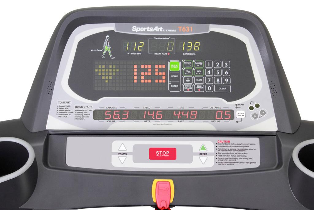
5 1-2. Display-T
6 1-3. Component Placement-T631 Display 1-3-1

7 1-3. Component Placement-T631 Display USB/CSAFE IPOD HTR Bridge 1-3-2
8 1-3. Component Placement T631 Drive Board Area 濾波器 AC 升降馬達組 SAC 伺服馬達 驅動器組 1-3-3
9 1-4. Block Diagram-T631 Polar Polar Display Cardio Keypad IPOD To ipod Safety key HTR Bridge ipod keys ipod earphone jack Sensor Sensor AC1 AC2 FUSE SW Inductor (220v) Filter Drive Motor Encoder Temperature sensor Incline motor Zero switch 1-4-1
10 1-5. Connections-T631 Display Board To telemetry HR receiver To USB/CSAFE To bridge (fan) 接至驅動器組 To bridge (safety key) To bridge (HTR brd) To bridge (keys) To ipod 1-5-1


11 1-5. Connections-T631 Bridge Board To display To HTR To safety key 1-5-2
12 1-5. Connections-T631 Drive Board To filter To motor thermal sensor To motor To incline motor To incline zero switch To display (signal) To display (power) To encoder 1-5-3
13 1-6. Indicator LEDs-T631 Display Board Power indicator Lit indicates display has power
 Incline down (green)")
14 1-6. Indicator LEDs-T631 Drive Board F1 fuse 15A Encoder indicator Condition indicator Normal: flashes continuously Incline up (orange) Incline down (green) 1-6-2
15 1-7. Display Specifications-T631 Specification Details Notes Exterior power 110V / 220V Motor SAC servo motor (with internal thermal sensor) 4.0 HP Optic sensor Magnetic encoder Speed range KPH : (KPH) MPH : (MPH) JAPAN: (KPH) Incline range Power: AC MOTOR (110V or 220V) Incline 0 % -15 % 0-point calibration, time controlled Every 1% = 2sec Illustration LED+14-segment LEDs+7-segment LEDs+dot matrix Programs MANUAL, RANDOM, HILL, INTV, FIT TEST, GLUTE Heart rate control program CARDIO/ WT LOSS, ZONE TRAINER Heart rate HTR/telemetry HR 1-7-1
16 2-1. Electronics Troubleshooting Chart-T631 Malfunction Circumstance Inspection and Testing Possible Part Notes Safety key Put safety key in place; there 1. Inspect display bridge and safety key Safety key malfunction is no reaction. connections. No start up No incline operation Telemetry heart rate Contact heart rate Key (display) Turn on power; display shows no reaction. Press the incline key; incline does not operate up or down. Telemetry heart rate malfunction Contact heart rate malfunction Key does not operate or operates continuously. Key(soft keys) Key does not operate or operates continuously. 2. Replace safety key. 1. Inspect main fuse. 2. Inspect drive fuse. 3. Inspect all cable connections. 4. Inspect display LED and program IC. 1. Inspect incline zero switch. 2. Inspect drive cable connections. 3. Replace drive. 4. Incline motor malfunction 1. Inspect heart rate transmitter and battery condition. Replace batteries if they are old. 2. Inspect the heart rate receiver cable connections. 3. Test or replace heart rate receiver. 4. Inspect environment for sources of interference, including speakers and lights. 1. Inspect HTR cable to the receiver. 2. Inspect HTR indicators. 3. Replace the HTR. 1. Replace display key switches or soft keys 1. Inspect bridge soft key connection. 2. Replace the soft key. 1. Main fuse 2. Drive 3. Cable 4. Display 1. Drive 2. Zero switch 1. Heart rate transmitter 2. Heart rate receiver 1.HTR 1. Display keys 2. Soft keys 1.Soft keys 2-1-1
17 ERR0R_1_1_ ERR0R_1_2_ Servo motor encoder malfunction Servo motor thermal sensor excessive heat; motor operates at half speed. 1. If encoder cable connection or encoder is worn, display directly shows ERROR 1_1. 2. Replace the motor Encoder. 1. Inspect the motor for excessive heat. 2. If the motor is not hot, inspect the thermal sensor cable connections. 3. Inspect treadmill walk belt tightness. Adjust or replace walk belt. ERROR_1_3_ Motor does not rotate 1. Motor does not rotate; display shows ERROR_1_3_. 2. Motor has an electrical open. Inspect the motor (red-white-black) wires for a break. 3. Replace the motor. ERROR_2_1_ IGBT over current 4. Re-start unit as a test. 5. If issue reoccurs repeatedly, replace SAC drive. ERR0R_2_2_ IGBT over temperature 1. Re-start unit as a test. 2. If issue reoccurs repeatedly, replace SAC drive. ERROR_2_3_ ERROR_3_1_ ERROR_3_1_ Drive circuit abnormality Incline motor calibration point error Incline motor calibration point error 1.Motor encoder 1.Walk belt 1.Motor 1.SAC drive 1. SAC drive 1. Please replace the drive. 1.SAC drive 1. Inspect cable connections. 1. SAC drive 2. After turning on unit, inspect whether incline motor is hot. If so, the drive is possibly 2. Incline zero bad. switch 1. After turning on unit, inspect whether incline calibrates to 0% position. If not, drive is possibly bad. 2. Inspect whether incline zero-point switch is normal
18 Power off Power OFF 1. Re-start unit as a test. 2. If issue reoccurs repeatedly, replace SAC drive. ERR0R_4_2_ Low voltage error 1. Power supply voltage is too low. 2. Inspect power supply voltage. Have power supply issue addressed immediately. 3.Re-start unit. Operate. Inspect for safety. ERROR_4_3_ High voltage error 1. Power supply voltage is too high. 2. Re-start unit. If message still appears, power supply voltage is too high. 3. Wait for voltage to drop to protect the treadmill. ERROR_8_1_ Communications error at 1. Cable is not connected. start ERROR_8_2_ Communications error after start 2. SAC drive malfunction 1. Inspect for sources of interference in the environment. 2. Inspect power supply ground. 3. Replace SAC drive. Main fuse blew Turn on unit; fuse blows. 1. Inspect for electrically shorted components. 2. Inspect cable connections for an electrical short. 3. Replace drive /incline/filter. Main fuse blew Main fuse blew Press speed key; motor fuse blows. In use, main fuse suddenly blew. 1. Inspect motor for abnormality. 2. Replace drive. 1. Inspect power supply. Is voltage too low? Normal: 110V or 220V +-10%. 2. Inspect walk belt tightness. 3. Inspect walk belt and walk deck for wear. 4. Lubricate the walk belt and walk deck. 5. Replace the SAC drive as a test. 1.SAC drive 1.SAC drive 1. SAC drive 1.SAC drive 1.SAC drive 1.Walk belt 2.SAC drive 2-1-3
19 SERVICE NEEDED - APPLY LUBE Display shows: SERVICE NEEDED - APPLY LUBE Every 4000 KM, this message occurs as a prompt to lubricate the walk belt and deck. Follow instructions in the owner manual to lubricate the walk belt and deck. Show total distance 1. Press <CHANGE> key for three seconds to set unit and view total distance, total time, and version numbers of display and drive firmware. HTR malfunction FOR ACCURATE HR,HOLD SENSORS FIRMLY WHILE WALKING 1. Firmly hold HTR contacts while exercising. 2. If you are holding HTR contacts firmly, inspect HTR contact cable connections


20 Troubleshooting Issue: Safety key malfunction Circumstance of malfunction: Put the safety key in place. The display does not operate. Display shows safety key. Possible cause: Safety key malfunction Troubleshooting: 1. Inspect the safety key magnet. 2. Inspect the bridge cable connections. 3. Test or replace the safety key. Safety key connection Display Bridge Safety key & safety key Bridge Safety key 3-1-1
21 Troubleshooting Issue: Unit will not start operating. Circumstance of malfunction: Turn power switch on. The display does not light. Possible cause: Inadequate power supply, or component damage. Troubleshooting: 1. Inspect the main fuse and power switch. 2.Inspect all cable connections. 3.Inspect the power switch indicator LED. 4.Inspect the display power indicator LED and main program IC. Cable connection Power indicator Program Display Filter AC1 FUSE SW Filter Fuse, switch Drive AC2 SAC drive The cable connect to display 3-2-1


22 Troubleshooting Malfunction: Soft key malfunction (display) Circumstance: Press a key on the display. There is no reaction. Or the key operates continually. Possible causes: 1. Soft keys are not connected. 2. Soft keys are bad. Troubleshooting: 1. Inspect the soft key connections. 2. Replace the soft keys. Soft key connector Display Keypad Keypad 3-3-1

23 Troubleshooting Malfunction: Soft key malfunction (display) Circumstance: Press a key on the display. There is no reaction. Or the key operates continually. Possible causes: 1.Soft keys are not connected. 2.Soft keys are bad. Troubleshooting: 1. Inspect the bridge soft key connections. 2. Replace the soft keys. Soft key connector Display Bridge Bridge Soft key connector Keypad


24 Troubleshooting Issue: No heart rate reading appears. Circumstance: No heart rate reading appears. Possible causes: 1. Heart rate transmitter battery power is insufficient. 2. Heart rate receiver is bad. 3. Environmental noise, such as lights and speakers, interferes with reception. Troubleshooting: 1. Replace transmitter or its batteries. 2. Inspect the telemetry heart rate receiver. 3. Replace the telemetry heart rate receiver. Display Telemetry heart rate receiver Red LED is heart rate signal indicator. Heart rate cable connector Heart rate transmitter (battery location) Heart rate receiver Transmitter 3-4-1


25 Troubleshooting Malfunction: Contact (Heart Touch Rate) malfunction Circumstance: Place hands on heart rate contact sensors. Heart rate values appear to be inaccurate. Possible causes: 1.HTR cable connection 2. HTR malfunction 3. Display cable connections Troubleshooting: 1. Inspect the display cable connections. 2. Inspect bridge HTR cable connections. 3. Inspect contact heart rate cable connections. 4. Inspect the HTR indicator LEDs. 5. Replace the HTR. Display HTR Indicators LED Name Function LED1 POLAR LED Flashing indicates incoming telemetry signal. LED2 HTR contact LED Lit indicates user is gripping HTR contact. LED3 HTR signal LED Flashing indicates incoming HTR signal. LED4 HR output Each flash indicates a pulse signal output. Display HTR connector Bridge HTR HTR cable HTR HTR HTR contact plate (clean here) Sensor-R Sensor-L 3-5-1
26 Troubleshooting Malfunction: The fuse breaks at start. Circumstance: The fuse breaks as soon as power is turned on. Possible cause: 1. Components have an electrical short. 2. Drive components are malfunctioning. Troubleshooting: 1. Remove the power cord. Test components for an electrical short. AC1 to a screw on the frame AC2 to a screw on the frame 3. Replace the drive as a test. AC1 AC2 FUSE SW Filter Drive 3-6-1
27 Troubleshooting Malfunction: The fuse breaks at motor startup. Circumstance: Press the speed up key to start the motor. The fuse breaks. Possible cause: 1. The motor has an internal electrical short. 2. The drive is malfunctioning. Troubleshooting: 1. Replace the drive as a test. 2. Replace the motor as a test. 3. Replace the encoder as a test. Display SAC drive Motor Encoder Encoder Motor SAC drive 3-6-2
28 Troubleshooting Malfunction: The fuse breaks during operation. Circumstance: After a period of use, the fuse breaks. Possible cause: 1.The fuse holder is not connected properly. 2. The walk deck or walk belt is worn. 3. The SAC drive is malfunctioning. Troubleshooting: 1.Inspect the fuse and fuse holder installation. 2. Inspect mechanical parts: A. Inspect the walk belt and drive belt for wear. Lubricate the walk belt. B. Inspect whether the walk belt is too tight or too lose. 3.Replace the SAC drive as a test. Display Motor SAC drive SAC drive Encoder Motor 3-6-3


29 Troubleshooting Malfunction: ERR0R_1_1_ Circumstance: Press the speed key. ERR0R_1_1_ appears. Possible cause: Motor encoder malfunction Troubleshooting: 1. Inspect cable connections. 2. Inspect the encoder signal indicator. If necessary, inspect the encoder for wear. 3. Replace the SAC drive. Remove motor back cover. Inspect encoder Encoder indicator Display 馬達 SAC drive Encoder Motor 3-7-1

30 Troubleshooting Model: T613 Malfunction: ERR0R_1_2 Circumstance: ERR0R_1_2 appears. Speed slows to half. Possible cause: 1. Walk deck and belt are worn. 2. Motor thermal sensor is malfunctioning, or there is a poor cable connection. Troubleshooting: 1. Inspect the thermal sensor on the motor. Low temperature: Electrically closed circuit. High temperature: Electrically open circuit. If not as above, the thermal sensor is bad. 2.When the message appears, if the motor temperature is high, the walk deck and belt are worn. Lubricate the walk deck and belt or replace the walk belt. 3. If the motor is not hot when the message appears, inspect whether the thermal sensor cable is connected. Display Thermal sensor SAC drive Motor Thermal sensor 3-8-1
31 Troubleshooting Model: T613 Malfunction: ERR0R_1_3_ Circumstance: The motor does not rotate. The display shows ERR0R_1_3. Possible causes: 1. The motor is stuck or has an electrical open. Troubleshooting: 1. Re-start the unit. Does the issue reappear? 2. Inspect all cable connections. 3. Inspect whether the motor is stuck. 4. Inspect whether the motor has an electrical open. 5. Inspect whether motor wires (red-black-white) have an electrical open. Display SAC drive Motor Motor 3-9-1
32 Troubleshooting Malfunction: ERR0R_2_1_, ERROR_2_2. Circumstance: Display shows ERR0R_2_1, ERROR_2_2. Possible causes: 1.SAC drive IGBT excessive heat or excessive current Troubleshooting: 1. Re-start the unit. Test to see whether the message appears again. 2. Stop the unit for ten minutes, and test it again. 3. If the message appears again, please replace the SAC drive. Display SAC drive Fuse 15A (Motor) SAC drive Motor
33 Troubleshooting Malfunction: ERR0R_2_3 Circumstance: Display shows ERR0R_2_3_. Possible cause: 1. Drive internal circuit abnormality. Troubleshooting: 1. Re-start the unit as a test. 2. Replace the SAC drive. Display SAC drive SAC drive Motor

34 Troubleshooting Malfunction: ERROR_3_1_ Circumstance: Turn on the treadmill. The incline does not return to the 0% position. Possible cause: 1. Drive or motor malfunction 2. Incline zero point calibration switch indicator malfunction Troubleshooting: 1. Inspect the incline fuse on the drive. 2. Inspect the incline UP/DOWN LEDs and measure the voltage to the incline motor. 3. Inspect zero switch operation. 4. Replace the drive or the incline motor unit. Incline voltage Incline up down Incline LED orange green Incline cable white-black white-red Zero point calibration switch Incline Worm gear 0% Touches switch 1-15% Not touching switch Zero switch on off Zero switch Display SAC drive UP LED (orange); DN LED (green) Zero SW AC incline unit Incline voltage 110V or 220V 110V or 220V
35 Troubleshooting Malfunction: ERROR_8_1_ Circumstance: After turning on the unit, the display shows ERROR_8-1. Possible cause: 1. Signal issue between the SAC drive and the display program Troubleshooting: 1. After turning on the unit, the display communicates with the drive. If communication does not occur, ERROR_8_1_ appears. 2.Inspect whether the SAC drive can start the unit. 3. Inspect the display/drive communication signal indicator LED on the drive. Normally, this LED flashes at a set frequency. 4. Replace the SAC drive or display program IC as a test. Display The cable connect to display (signal) Drive
36 Troubleshooting Malfunction: ERROR_8_2_ Circumstance: During operation, the display shows ERROR_8_2_. Possible cause: 1. Interference of communication between the display and drive s Troubleshooting: 1. Inspect the display-to-drive data cable connection. 2.After the error message appears, re-start the unit. This may clear the communication issue and thereby clear the error message. 3.If the message does not clear after re-starting the unit, replace the SAC drive. Display Drive The cable connect to display (signal)
37 Troubleshooting Malfunction: SERVICE NEEDED-APPLY LUBE Circumstance: The message SERVICE NEEDED-APPLY LUBE appears, and the unit stops operating. At 4000 km of use, the lubrication service prompt SERVICE NEEDED-APPLY LUBE appears. Troubleshooting: 1. Insert the lube applicator tube as shown. 2. Simultaneously press and hold <PROGRAM SCROLL>+INCLINE< >+INCLINE< > for two seconds to activate the lubrication mode. The display counts down (3, 2, 1). The speed window shows 2.0 kph (or 1.3 mph), and the walk belt starts rotating. 3. Squeeze the bottle of lubricant into the applicator tube. Let the unit operate slowly for ten minutes. Allow the lubricant to disperse onto the walk belt. 4. After ten minutes, press the <STOP> key and remove the lube applicator tube. The display program will clear the lube distance memory. A new lubrication distance will begin to accrue. 5. After lubricating the walk belt, operate the treadmill for ten minutes to let the lubricant disperse
38 Other Instructions Item: Unit settings and information: KPH/MPH units, distance, time, display program, and drive program versions. Method: 1. Press and hold the <CHANGE> key for three seconds to enter the user setting mode. 2. Metric/imperial unit setting: Display shows UNIT-MPH (imperial) or UNIT-KPH (metric) units. Press the INCLINE< > or < > keys to toggle between MPH and KPH settings. Then press the <ENTER> key to confirm your choice. 3. Total distance The display shows DIST-XXXXXXKM, followed by numbers which represent the total the distance of the walk belt rotation. Press the <ENTER> key to proceed to the next setting. 4. Total time The display shows TIME-XXXXXXHOUR, followed by numbers which represent the total time of use. Press the <ENTER> key to proceed to the next setting. 5. Display program version Press the INCLINE < > key to view the display program version, for example, CTL XT631H-1A. Press the ENTER key to exit the program. 6. Drive program version Press the INCLINE < > key to view the drive program version, for example, DRV SAC--AF. Press the <ENTER> key to exit the program
39 Other Instructions Item: Error messages E1_1 : Servo motor encoder abnormality. Re-start the unit. E1_2 : Servo motor excessive heat warning. Motor operates at half speed. E1_3 : The motor does not rotate; the motor is stuck or has an electrical open. E2_1 : IGBT over current. Turn off unit. Let it sit idle 10 minutes before restarting the unit. E2_2 : IGBT excessive heat warning. Motor operates at half speed. E2_3 : The current sensor on the drive detects excessive current; the drive has an issue. E3_1 : Incline motor calibration point abnormality. POWER OFF : Power switch is OFF. E4_2 : Power supply voltage is too low. Wait until voltage returns to normal before starting the unit. E4_3 : Power supply voltage is too high. Wait until voltage returns to normal before starting the unit. E8_1 : Communication abnormality at start up. E8_2 : Communication abnormality during use

40 Inspecting and Testing Name: Test for an electrical open on the AC servo motor Method: 1. Disconnect motor wires. Set the voltmeter to the ohm setting. Place red and black probes separately on motor wires as indicated. Normal readings: Motor wires Ohm setting Notes green-black No reaction The green wire is the ground wire green-white No reaction The green wire is the ground wire green-red No reaction The green wire is the ground wire black-white Short black-red Short white-red Short 2.If the black-white, black-red, or white-red wires have an electrical open, the motor has a broken wire. ERRROR 1_3_ will appear

 1-15% OFF (open)")
41 Inspecting and Testing Name: Incline zero point switch inspection Method: 1. Press the INCLINE< > or < > key. Inspect the incline and zero point switch operation. 2. Zero point switch operation Incline Zero switch 0% ON (close) 1-15% OFF (open) Incline 0%: zero switch operates Incline 1-15%: zero switch does not operate 4-1-2


42 Inspecting and Testing Name: Incline zero point switch inspection Method: 1.Turn on power. At 0% incline, the zero switch is touched by the worm gear; The zero switch is on (electrically closed ). At 1%-15%, the zero switch is not touched by the worm gear; The zero switch is off (electrically open ). Zero switch Incline Tube Zero switch Picture % Touches switch on 1-15% Does not touch switch off

; DN LED (green) Incline voltage cable Display Drive UP (orange) DOWN (green) Black Red")
43 Inspecting and Testing Name: Incline motor voltage test Method: 1.Set the voltmeter to the 300 VAC or higher voltage setting. 2.Press INCLINE< >/< > keys. Incline indicator LEDs on the drive light. Measure voltage output to the incline motor. Normal readings are shown below. Display Drive Incline motor cables Incline operates Press < > key UP (orange) lights white-black 110V or upward 220V Press < > key DOWN (green) lights white-red 110V or 220V downward Up LED (orange); DN LED (green) Incline voltage cable Display Drive UP (orange) DOWN (green) Black Red White Incline motor 4-3-1

44 Inspecting and Testing Name: Motor thermal sensor test Method: 1.When the temperature of the motor is normal, the display operates without any abnormality. Remove the motor thermal sensor cable. The display shows SERVICE REQUIRED 2.When the motor has been used for a long period of time, and the display shows SERVICE REQUIRED touch the motor; The motor surface feels hot
45 Inspecting and Testing Name: SAC motor encoder indicator test Method: 1.Turn on power. The display lights. The display shows ERROR 1_1. ERROR 1_1 usually indicates an encoder issue. 2. When the motor rotates, the drive encoder LED flashes. 3. When ERROR 1_1 appears, remove the encoder cover. Inspect whether the encoder has wear. Remove the motor cover. Inspect whether the encoder is worn. Encoder indicator 4-5-1
T652 Repair Manual (Electronics)
") T652 Repair Manual (Electronics) Table of Contents 1-1-1. Product Illustration T652 1-2-1. Display T652 1-3-1. Component Placement T652 Display 1-3-2. Component Placement T652 Drive Compartment 1-4-1.
T652 Repair Manual (Electronics) Table of Contents 1-1-1. Product Illustration T652 1-2-1. Display T652 1-3-1. Component Placement T652 Display 1-3-2. Component Placement T652 Drive Compartment 1-4-1.
T621 Repair Manual (Electronics)
") T621 Repair Manual (Electronics) Table of Contents 1-1-1. Product Picture-T621 1-2-1. Display-T621 1-3-1. Component Placement-T621 Display 1-3-2. Component Placement-T621 Drive Board Area 1-4-1. Block
T621 Repair Manual (Electronics) Table of Contents 1-1-1. Product Picture-T621 1-2-1. Display-T621 1-3-1. Component Placement-T621 Display 1-3-2. Component Placement-T621 Drive Board Area 1-4-1. Block
T611 Repair Manual (Electronics)
") T611 Repair Manual (Electronics) Table of Contents 1-1-1. Product Picture T611 1-2-1. Overlay T611 1-3-1. Component Placement T611 Display Board 1-3-2. Component Placement T611 Lower Compartment 1-4-1.
T611 Repair Manual (Electronics) Table of Contents 1-1-1. Product Picture T611 1-2-1. Overlay T611 1-3-1. Component Placement T611 Display Board 1-3-2. Component Placement T611 Lower Compartment 1-4-1.
TR22F Repair Manual (Electronics)
") TR22F Repair Manual (Electronics) Table of Contents 1-1-1. Product Picture - TR22F 1-2-1. Overlay - TR22F 1-3-1. Component Placement - TR22F Display Board 1-3-2. Component Placement - TR22F Lower Compartment
TR22F Repair Manual (Electronics) Table of Contents 1-1-1. Product Picture - TR22F 1-2-1. Overlay - TR22F 1-3-1. Component Placement - TR22F Display Board 1-3-2. Component Placement - TR22F Lower Compartment
C520U/C531U Repair Manual
 C520U/C531U Repair Manual Table of Contents 1-1-1. Display Picture C520/C531 1-2-1. Component Placement - C520U/C531U Display 1-2-2. Component Placement - C520U/C531U Lower Body 1-3-1. Block Diagram -
T630 Treadmill Repair Manual SPORTS ART INDUSTRIAL CO., LTD.
 T630 Treadmill Repair Manual SPORTS ART INDUSTRIAL CO., LTD. Table of Contents 1. Unit Components 1-1-1. T630 Product Picture 1-1-2. T630 Treadmill Components (1) Display Area 1-1-3. T630 Treadmill Components
WARNING: ALWAYS UNPLUG THE TREADMILL FROM THE ELECTRICAL OUTLET BEFORE SERVICING THE UNIT.
 Z700-A82 / 120V Treadmill WARNING: ALWAYS UNPLUG THE TREADMILL FROM THE ELECTRICAL OUTLET BEFORE SERVICING THE UNIT. Table of Contents TABLE OF CONTENTS Table of Contents...1 Table of Figures...3 Description...4
WARNING: ALWAYS UNPLUG THE TREADMILL FROM THE ELECTRICAL OUTLET BEFORE SERVICING THE UNIT.
 Z100-A81 CE Treadmill WARNING: ALWAYS UNPLUG THE TREADMILL FROM THE ELECTRICAL OUTLET BEFORE SERVICING THE UNIT. Table of Contents TABLE OF CONTENTS Table of Contents...1 Table of Figures...3 Description...4
LS8.0T Service Manual
 LS8.0T Service Manual 1 TABLE OF CONTENTS CHAPTER 1: SERIAL NUMBER LOCATION...3 CHAPTER 2: PREVENTATIVE MAINTENANCE 2.1 Preventative Maintenance. 4 2.2 Tension and Centering the Running Belt....6 CHAPTER
TROUBLESHOOTING TROUBLESHOOTING
 FOR 2007 TREADMILLS: (T9200 SIMPLE, T9500 SIMPLE, T9600 SIMPLE, T9250 SIMPLE, T9450 SIMPLE) (T9200 DELUXE, T9500 DELUXE, T9600 DELUXE, T9250 DELUXE, T9450 DELUXE) (T9200 PREMIER, T9500 PREMIER, T9600 PREMIER,
T & T Service Manual
 T101-04 & T202-03 Service Manual 1 2 3 Contents CHAPTER 1: SERIAL NUMBER LOCATION... 6 CHAPTER 2: PREVENTATIVE MAINTENANCE 2.1 Preventative Maintenance... 8 2.2 Tension and Centering the Running Belt...
Section Five - Troubleshooting Procedures
 Section Five - Troubleshooting Procedures Note: This section contains troubleshooting procedures specific to the C96X family of treadmills. Please refer to the troubleshooting procedures in the commercial
2013 Elite T4000 (TM461C) Service Manual
 Service Manual") 2013 Elite T4000 (TM461C) Service Manual 1 TABLE OF CONTENTS CHAPTER 1: SERIAL NUMBER LOCATION...3 CHAPTER 2: PREVENTATIVE MAINTENANCE 2.1 Preventative Maintenance. 4 2.2 Tension and Centering the Running
2013 Elite T4000 (TM461C) Service Manual 1 TABLE OF CONTENTS CHAPTER 1: SERIAL NUMBER LOCATION...3 CHAPTER 2: PREVENTATIVE MAINTENANCE 2.1 Preventative Maintenance. 4 2.2 Tension and Centering the Running
C960, C962, C964 Treadmill
 C960, C962, C964 Treadmill Warning: This service manual is for use by Precor trained service providers only. If you are not a Precor Trained Servicer, you must not attempt to service any Precor Product;
C954, C956 Treadmill
 C954, C956 Treadmill Warning: This service manual is for use by Precor trained service providers only. If you are not a Precor Trained Servicer, you must not attempt to service any Precor Product; Call
9.2, 9.2s, 9.20, 9.20s Treadmill
 9.2, 9.2s, 9.20, 9.20s Treadmill Warning: This service manual is for use by Precor trained service providers only. If you are not a Precor Trained Servicer, you must not attempt to service any Precor Product;
9.25, 9.25i Treadmill
 9.25, 9.25i Treadmill Warning: This service manual is for use by Precor trained service providers only. If you are not a Precor Trained Servicer, you must not attempt to service any Precor Product; Call
9.31, 9.33, 9.35 Treadmill
 9.31, 9.33, 9.35 Treadmill Warning: This service manual is for use by Precor trained service providers only. If you are not a Precor Trained Servicer, you must not attempt to service any Precor Product;
9.17, 9.17si Treadmill
 9.17, 917si Treadmill 9.17, 9.17si Treadmill Warning: This service manual is for use by Precor trained service providers only. If you are not a Precor Trained Servicer, you must not attempt to service
9.33i, 9.35i Treadmill
 9.33i, 9.35i Treadmill Warning: This service manual is for use by Precor trained service providers only. If you are not a Precor Trained Servicer, you must not attempt to service any Precor Product; Call
9.45, 9.45i Treadmill
 9.45, 9.45i Treadmill Warning: This service manual is for use by Precor trained service providers only. If you are not a Precor Trained Servicer, you must not attempt to service any Precor Product; Call
C966 Treadmill. C966 Treadmill
 C966 Treadmill Warning: This service manual is for use by Precor trained service providers only. If you are not a Precor Trained Servicer, you must not attempt to service any Precor Product; Call your
9.31, 9.33, 9.35 Treadmill
 9.31, 9.33, 9.35 Treadmill Warning: This service manual is for use by Precor trained service providers only. If you are not a Precor Trained Servicer, you must not attempt to service any Precor Product;
C954, C956 Treadmill
 C954, C956 Treadmill Warning: This service manual is for use by Precor trained service providers only. If you are not a Precor Trained Servicer, you must not attempt to service any Precor Product; Call
LS10.0T Service Manual
 LS10.0T Service Manual 1 TABLE OF CONTENTS CHAPTER 1: SERIAL NUMBER LOCATION...3 CHAPTER 2: PREVENTATIVE MAINTENANCE 2.1 Preventative Maintenance. 4 2.2 Tension and Centering the Running Belt....6 CHAPTER
C944 Treadmill. C944 Treadmill
 C944 Treadmill Warning: This service manual is for use by Precor trained service providers only. If you are not a Precor Trained Servicer, you must not attempt to service any Precor Product; Call your
JBI Docupunch P33 Automatic Punch
 JBI Docupunch P33 Automatic Punch Instruction Manual Provided By http://www.mybinding.com http://www.mybindingblog.com TABLE OF CONTENTS SECTION I: INSTALLATION & TESTING: 1) Uncrating, Inspection & removal
1. OVERVIEW DRAWING 2
 1 1. OVERVIEW DRAWING 2 2. IMPORTANT SAFETY INSTRUCTIONS When using an electrical appliance, basic precautions should always be followed, including the followings: Read all instructions before using the
About this Troubleshooting Document
 About this Troubleshooting Document This document lists the error codes that exist within the Precor software hierarchy. Each section will include a description of the error code being displayed and the
Modulating Furnace Information. Warning on Meter Setting - Read First!
 Modulating Furnace Information Pressure Transducer Pressure DC Volts 0.00" 0.25 0.20" 0.63 0.25" 0.72 0.30" 0.82 0.35" 0.91 0.40" 1.00 0.45" 1.09 0.50" 1.19 0.55" 1.28 0.60" 1.38 0.65" 1.47 0.70" 1.56
9.31, 9.33, 9.35 Treadmill
 Warning: This service manual is for use by Precor trained service providers only. If you are not a Precor Trained Servicer, you must not attempt to service any Precor Product; Call your dealer for service.
Check the wires going to the back of the computer, if the wires are secure and console will not start see step b.
 ELECTRONIC TROUBLESHOOTING 1. PROBLEM: Console LED's will not light, console will not power up The bike must be pedaled at greater than 50 RPM while Check the wires going to the back of the computer, if
5002/5005 Bike Repair Guide Version 2; Date:
 5002/5005 Bike Repair Guide Version 2; Date: 10-26-04 5002 recumbent bike 5005 upright bike Note: Electronics in 5002 and 5005 are basically the same, but displays differ. Unique Technical Features of
9.33, 9.35 Treadmill
 9.33, 9.35 Treadmill Warning: This service manual is for use by Precor trained service providers only. If you are not a Precor Trained Servicer, you must not attempt to service any Precor Product; Call
C966 Treadmill Warning:
 C966 Treadmill Warning: This service manual is for use by Precor trained service providers only. If you are not a Precor Trained Servicer, you must not attempt to service any Precor Product; Call your
9.33i, 9.35i Treadmill
 9.33i, 9.35i Treadmill Warning: This service manual is for use by Precor trained service providers only. If you are not a Precor Trained Servicer, you must not attempt to service any Precor Product; Call
C956i, C966i Treadmill
 C956i, C966i Treadmill Warning: This service manual is for use by Precor trained service providers only. If you are not a Precor Trained Servicer, you must not attempt to service any Precor Product; Call
OPERATING INSTRUCTIONS IC-2, 3,4,5,6 INTELLICUT SERVO CUTTER Version 5.1xx Created 11/2009
 OPERATING INSTRUCTIONS IC-2, 3,4,5,6 INTELLICUT SERVO CUTTER Version 5.1xx Created 11/2009 "CAUTION" "DO NOT OPERATE MACHINE WITH GUARD REMOVED" UNCRATE AND INSPECT This machine has been carefully crated
C.E. Niehoff & Co. C653/C653A and C625 Alternators Troubleshooting Guide NOTICE. Hazard Definitions. Battery Charge Volt and Amp Values
 C.E. Niehoff & Co. C653/C653A and C625 Alternators Troubleshooting Guide Hazard Definitions These terms are used to bring attention to presence of hazards of various risk levels or to important information
True Fitness Service Manual. 455 Pediatric Treadmill
 True Fitness Service Manual 455 Pediatric Treadmill True fitness technology, Inc. makes no representations or warranties regarding the contents of this manual. We reserve the right to revise this document
9.57 Treadmill Warning:
 9.57 Treadmill Warning: This service manual is for use by Precor trained service providers only. If you are not a Precor Trained Servicer, you must not attempt to service any Precor Product; Call your
Symptom Possible Cause Test Procedure Repair
 Troubleshooting Guide: E2 Error/Erratic Speed Prepared by: Regina Templeton Date Prepared: 12/07/2015 E2 error on a unit with an analog speed sensor (The analog speed encoder signal indicates speed is
MONITOR INSTALLATION AND OPERATING INSTRUCTIONS VERSION
 2200 Simplicity 3x 2200 SURVEILLANCE SIMPLICITY 3x AIRSEEDER MONITOR INSTALLATION AND OPERATING INSTRUCTIONS VERSION 1.00 2200 Surveillance Simplicity Air Seeder Page 2 CONTENTS 1.0 INSTALLATION... 3 1.1
ERROR CODES BIKES CROSS TRAINING
 BIKES ERROR CODES 3610, 3670, 3710, 3770, The BIKE and SEMI System stall System will not calibrate Belt worn, broken or off flywheel X Large red X displayed Replace display or send in for repair 3900,
MX-T3x(TM94E) AC SYSTEM SERVICE MANUAL
 AC SYSTEM SERVICE MANUAL") MX-T3x(TM94E) AC SYSTEM SERVICE MANUAL 1 TABLE OF CONTENTS SECTION 1:SERIAL NUMBER LOCATION SECTION 2:MOVING THE UNIT SECTION 3:IMPORTANT SAFETY INSTRUCTIONS SECTION 4:PREVENTATIVE MAINTENANCE 4.1 Maintenance
MX-T3x(TM94E) AC SYSTEM SERVICE MANUAL 1 TABLE OF CONTENTS SECTION 1:SERIAL NUMBER LOCATION SECTION 2:MOVING THE UNIT SECTION 3:IMPORTANT SAFETY INSTRUCTIONS SECTION 4:PREVENTATIVE MAINTENANCE 4.1 Maintenance
Attention! 1 Accessories. 2-1 Installation description ❹ ❺. Please proceed as follows
 Thank you for purchasing the TNT-B meter for Yamaha Bolt. Before installing, please read the instruction carefully and keep it for future reference. Attention! For installation, please follow the steps
Setup and Programming Manual
 Microprocessor and Handy Terminal Setup and Programming Manual Versions U04 to U19 for Sliding Door Systems P/N 159000 Rev 7-2-07 The manufacturer, NABCO Entrances, Inc. suggests that this manual be given
Furnace Web Site FAQs. Pro Press 100 / Pro 100 / Pro 100 plus. Lift. Belt Noise
 Furnace Web Site FAQs Pro Press 100 / Pro 100 / Pro 100 plus Lift Belt Noise A Worn belt Over time the belt may become dry or worn due to heat and travel. Replace the belt Tight If the belt was recently
EA07. Generator Automatic Voltage Regulator Operation Manual
 EA07 Generator Automatic Voltage Regulator Operation Manual Suitable for Single or Three Phase Self Excited Brushless Generator Compatible replacement for Mecc Alte SR-7 * Not a genuine Mecc Alte product.
PANcharge1k Battery Charger User's Manual
 PANcharge1k Battery Charger User's Manual Ver.1.00E Table of Contents 1. Important Safety Instructions... 3 1-1 General Safety Precautions... 3 1-2 Battery Precautions... 3 1-3 Electromagnetic Disturbance...
UNITED STATES Ford Customer Relationship Center (FORD) (TDD for the hearing impaired: ) owner.ford.
 (TDD for the hearing impaired: ) owner.ford.") CARD/STICKERS/POCKET (SLEEVE) IMPORTANT: Pro Trailer Backup Assist depends on how and where you place the sticker. Do not attempt to place the sticker until you read through all of Step 3 on pages 9 and
CARD/STICKERS/POCKET (SLEEVE) IMPORTANT: Pro Trailer Backup Assist depends on how and where you place the sticker. Do not attempt to place the sticker until you read through all of Step 3 on pages 9 and
SYMBOL LEGEND DANGER WARNING NOTE THIS INDICATES DANGER TO THE LIFE AND HEALTH OF THE USER IS APPROPRIATE PRECAUTIONS ARE NOT TAKEN
 SYMBOL LEGEND DANGER THIS INDICATES DANGER TO THE LIFE AND HEALTH OF THE USER IS APPROPRIATE PRECAUTIONS ARE NOT TAKEN WARNING THIS WARNS THAT MATERIALS MAY BE DAMAGED IF APPROPRIATE PRECAUTIONS ARE NOT
AFT mid drive kit Trouble shooting guide For 24v to 48V Kelly Controller KBS 48101L-L 100 A peak
 Date: 2016-13-1 AFT mid drive kit trouble shooting guide Rev 1.7 Page 1 of 17 AFT mid drive kit Trouble shooting guide For 24v to 48V Kelly Controller KBS 48101L-L 100 Table of Contents 1. Safety... 2
Cybex Arc Trainer Owner s & Service Manual. 7 - Service
 7 - Service Table of Contents......... iii Warnings/Cautions All warnings and cautions listed in this chapter are as follows:! WARNING: All maintenance activities shall be performed by qualified personnel.
TC1000 Service Manual SALES: CUSTOMER SERVICE:
 TC1000 Service Manual SALES: 800-278-3933 CUSTOMER SERVICE: 800-745-1373 Table of Contents Section Page I. Overview 2 II. Troubleshooting Tables 3 III. Maintenance Procedures Procedure 1 Removal and Reinstallation
CONTROL BOX. Wiring the control box into the vehicle. +12V
 CONTROL BOX Once the display panel is in place, mount the control box within the connecting cable's distance (approximately 3 feet) and secure to the underside of the dashboard. This case does not have
CRUISE CONTROL SYSTEM
 CRUISE CONTROL SYSTEM 1994 Volvo 960 1994 ACCESSORIES/SAFETY EQUIPMENT Cruise Control System 960 DESCRIPTION & OPERATION MAIN SWITCH Cruise control main switch is located at end of directional signal lever.
T 1 x T r e a d m i l l S e r V i C e m a N U a l
 T1x-04 Treadmill SERVICE MANUAl Table of contents CHAPTER 1: Serial number location... 1 CHAPTER 2: Important Safety instructions 2.1 Before Getting Started... 2 2.2 Read and Save These Instructions...
#97-T-20A: MIL (Service Engine Soon Telltale Lamp) On and EGR DTCs P0401, P0404, P0405, P1404 and/or P1406 in PCM Memory - (Jan 6, 2003)
 On and EGR DTCs P0401, P0404, P0405, P1404 and/or P1406 in PCM Memory - (Jan 6, 2003)") #97-T-20A: MIL (Service Engine Soon Telltale Lamp) On and EGR DTCs P0401, P0404, P0405, P1404 and/or P1406 in PCM Memory - (Jan 6, 2003) Subject: Malfunction Indicator Lamp (SERVICE ENGINE SOON Telltale
#97-T-20A: MIL (Service Engine Soon Telltale Lamp) On and EGR DTCs P0401, P0404, P0405, P1404 and/or P1406 in PCM Memory - (Jan 6, 2003) Subject: Malfunction Indicator Lamp (SERVICE ENGINE SOON Telltale
CONTENTS TABLE OF CONTENTS... 1 INTRODUCTION... 2 SEC 1 - SPECIFICATIONS... 3 SEC 2 - DESCRIPTION... 5 SEC 3 - OPERATING INSTRUCTIONS...
 CONTENTS SUBJECT PAGE TABLE OF CONTENTS... 1 INTRODUCTION... 2 SEC 1 - SPECIFICATIONS... 3 SEC 2 - DESCRIPTION... 5 SEC 3 - OPERATING INSTRUCTIONS... 8 SEC 4 - BATTERY CHARGING NOTES... 9 SEC 5 - VERIFICATION
Read Chapter 8 Servicing Machine in the Manual for general guidelines
 Page 1 of 6 Read Chapter 8 Servicing Machine in the Manual for general guidelines The PlasmaCAM will not work on a GFI circuit. Earth ground the grates of the PlasmaCAM. Computer Configuration A. PlasmaCAM
Gentex by VOXX Corporation Installation Instructions
 Gentex by VOXX Corporation Installation Instructions Bezelled ADVGEN45A4 Bezelled w/ Homelink ADVGEN80EXP ADVGEN45A4PW4 ADVGEN40A4 Frameless ADVGEN8EXP Frameless w/ Homelink ADVGEN85EXP ADVGEN45AB5 TOOLS
ELECTRIC FENCE ENERGIZER SERVICE MANUAL MODEL 950 SERVICE MANUAL FOR OLLI 950 FENCE ENERGIZERS
 ELECTRIC FENCE ENERGIZER MODEL 950 SERVICE MANUAL Service Manual for OLLI 950 Page 1/16 Date 20.10.2014 Table of Contents...1 1. IMPORTANT SAFETY INSTRUCTIONS...2 2. SPECIFICATIONS...3 3. CONSTRUCTION...4
Sears Canada Service Manual
 Sears Canada Service Manual Treadmills Models 30750, 30727 Table of Contents >> Table of Contents Section One Section Two Safety Instructions 3 Horizon Fitness 5-Step Diagnostic Process 13 Recommended
HP21 SERVICE SUPPLEMENT UNIT INFORMATION. TSC6 Two-Speed Control
 SERVICE UNIT INFORMATION SUPPLEMENT HP21 Corp. 9426 L10 Litho U.S.A. All HP21-4 and -5 units (single and three phase) are equipped with a TSC6 two-speed control. The TSC6 (A14) two-speed control contains
Owner s Manual Currency Counter
 Owner s Manual 4820 Currency Counter TABLE OF CONTENTS 1. Product View 1.1. Front and Rear Views 1.2. LED Display/Control Panel 1.3. Side Control Panel 2. Operation 2.1 Operation Modes 2.2 The Right Way
Console Cable Troubleshooting Bike and Elliptical
 Prepared by: Emilie McWilliams Date Prepared: 4/9/2015 Models Affected: AFG, Horizon, Livestrong, and Vision bikes and ellipticals 2001 - present DESCRIPTION Use this guide to troubleshoot an analog console
ION-01-6 PERFORMANCE SPEEDOMETER/TACHOMETER COMBO
 ION-01-6 PERFORMANCE SPEEDOMETER/TACHOMETER COMBO MOUNTING: It should be inserted into the opening from the front and the L-clamps will be installed from the back. Tighten the nuts on the L-clamps so that
C762, C764, C764i Stairclimber
 C762, C764, C764i Stairclimber Warning: This service manual is for use by Precor trained service providers only. If you are not a Precor Trained Servicer, you must not attempt to service any Precor Product;
Error Code Troubleshooting Guide. Revised (11/2017)
") Error Code Troubleshooting Guide Revised (11/2017) Table of Contents (click error to go to page) About this Document... 5 List of Changes... 5 01, 02, 03, 04... 6 Memory, Ram & EEPROM Test Errors... 6
Error Code Troubleshooting Guide Revised (11/2017) Table of Contents (click error to go to page) About this Document... 5 List of Changes... 5 01, 02, 03, 04... 6 Memory, Ram & EEPROM Test Errors... 6
Table of Contents. General Operation. 3 How Slam-A-Winner plays How the Wheel Scores How the Ball Lift works Programming Options...
 61-MAN-B Table of Contents General Operation. 3 How Slam-A-Winner plays How the Wheel Scores How the Ball Lift works Programming Options... 4-6 Troubleshooting Guide. 7-8 Parts Identification 9 Schematics
SECOND GENERATION Use this guide with unit serial number prefix beginning with BWF using Terra Power separator.
 Technical Information and Diagnostic Guide for SECOND GENERATION Use this guide with unit serial number prefix beginning with BWF using Terra Power separator. This guide will assist you in becoming more
TROUBLESHOOTING GENERATOR UNITS
 TROUBLESHOOTING GENERATOR UNITS Figure 3.17 Troubleshooting Flow Chart For Direct Excited (Brush Type) Generators or later. 68 Troubleshooting Direct Excited (Brush Type) Generators Refer to Figure 3.17
ACCUSENSE CHARGE SERIES ON/OFF BOARD FULLY AUTOMATIC BATTERY CHARGER
 ACCUSENSE CHARGE SERIES ON/OFF BOARD FULLY AUTOMATIC BATTERY CHARGER SPECIFICATIONS: *Photo for reference only* Part number 8890439 Mode Select: Selects Battery Type Refer to Section 6. IMPORTANT: READ
Lifecycle 9500HR/9100 Series Recumbent Exercise Bikes Customer Support Services SERVICE MANUAL
 Lifecycle 9500HR/9100 Series Recumbent Exercise Bikes Customer Support Services SERVICE MANUAL INTRODUCTION HOW TO USE SERVICE MANUAL AND CONTACT CUSTOMER SUPPORT SERVICES This service manual is applicable
e-ask electronic Access Security Keyless-entry
 e-ask electronic Access Security Keyless-entry Multiplex System Multiplex System Installation & Instructions (UM15 ~ 22272-03) Table of Contents Introduction... 1 Standard e-fob Operation and Features...
No Operation of air conditioner Explanation
 12. Troubleshooting 12-1 Items to be checked first 1. The input voltage should be rating voltage ±10% range. The air conditioner may not operate properly if the voltage is out of this range. 2. Is the
DIAGNOSTIC TROUBLESHOOTING INDEX
 DIAGNOSTIC TROUBLESHOOTING INDEX Curtis Industries, LLC. 111 Higgins Street Worcester, MA 01606 Telephone: (508) 853-2200 Fax: (800) 876-9104 www.snoproplows.com TROUBLESHOOTING INDEX - BY PROBLEM Section
(Designed & Manufactured by RC EXPLORER TEAM) Radon V2 series Brushless Speed Control System User Guidelines
 Radon V2 series Brushless Speed Control System User Guidelines") (Designed & Manufactured by RC EXPLORER TEAM) Radon V2 series Brushless Speed Control System User Guidelines 1. Technical /Specifications: Model: Radon Pro V2 Radon Pro V2 1S Radon Sport V2 Continuous
(Designed & Manufactured by RC EXPLORER TEAM) Radon V2 series Brushless Speed Control System User Guidelines 1. Technical /Specifications: Model: Radon Pro V2 Radon Pro V2 1S Radon Sport V2 Continuous
Technical Installation and Service Manual RollSeal 1733 County Road 68 Bremen, Alabama 35033
 Technical Installation and Service Manual RollSeal 1733 County Road 68 Bremen, Alabama 35033 4801-5159 rev. 05/14 Technical Installation and Service Manual Page 1 of 26 1. Ratings and Specifications Motor
BIM-17-2 Bus Interface Module for compass and outside temperature
 BIM-17-2 Bus Interface Module for compass and outside temperature Mount the temperature sensor in the front grill area or another location that can get good air flow while the vehicle is being driven.
The following procedures should be observed to ensure safe driving.
 Driving the vehicle The following procedures should be observed to ensure safe driving. n Starting the hybrid system ( P. 162) n Driving STEP 1 With the brake pedal depressed, shift the shift lever to
C576i Self Powered Elliptical Fitness Crosstrainer
 C576i Self Powered Elliptical Fitness Crosstrainer Warning: This service manual is for use by Precor trained service providers only. If you are not a Precor Trained Servicer, you must not attempt to service
CRUISE CONTROL SYSTEM
 CRUISE CONTROL SYSTEM 1988 Jeep Cherokee 1988 Cruise Control Systems JEEP CRUISE COMMAND All Models DESCRIPTION & OPERATION Jeep vehicles use an electro-mechanical servo system. The system consists of
SAVANNAH EI & DELUXE SYSTEM TROUBLE SHOOTING GUIDE
 SAVANNAH EI & DELUXE SYSTEM TROUBLE SHOOTING GUIDE ***PLEASE MAKE SURE TO LEARN THE REMOTE TO THE SYSTEM (REFER TO PG 6) AND CHECK THE BATTERIES FIRST!!! (American Flame AF-4000 Series) Intermittent Pilot
Intelli-Feed Controller User s Manual Intelli-Feed Digital Tachometer and Hourmeter
 Intelli-Feed Controller User s Manual Intelli-Feed Digital Tachometer and Hourmeter Part #: 9047 Table of Contents: Table of Contents 2 Intelli-Feed TM User Interface 3 Equipment Diagnostic Indicators
6 Litre Oil-Less Air Compressor
 Operator s Manual 6 Litre Oil-Less Air Compressor WARNING! Before using this appliance, read the Operator s manual and follow all its safety rules and instructions. SPECIFICATION HWKAC1 1.1 kw / 1.5 HP
BIGLA30-T/BIELA14-T Event Codes Quick Reference EXPLANATION CORRECTIVE ACTION PARTS TO CARRY ON SERVICE CALL
 E13 TEMPERATURE PROBE FAILURE E16 HIGH LIMIT 1 EXCEEDED A. TEMP Probe reading out of range. B. Bad Connection. C. Problem with the temperatur e measuring circuitry including the probe. High limit temperature
HLY-3016 PERFORMANCE SPEEDOMETER/TACHOMETER COMBO (weather and vibration resistant for exposed environments)
") HLY-3016 PERFORMANCE SPEEDOMETER/TACHOMETER COMBO (weather and vibration resistant for exposed environments) *To avoid damage to motorcycle, please see Speedometer, Tachometer, and Status and Warning Indicators
HLY-3016 PERFORMANCE SPEEDOMETER/TACHOMETER COMBO (weather and vibration resistant for exposed environments) *To avoid damage to motorcycle, please see Speedometer, Tachometer, and Status and Warning Indicators
Table of Contents. Timer Identification Timer ID BLU-U Features: 1K 6K BLU-U Features 1K 6K
 DUSA Pharmaceuticals, Inc. Table of Contents Go to Chart # Timer Identification Timer ID BLU-U Features: 1K 6K BLU-U Features 1K 6K BLU-U Features: 10K BLU-U Features 10K BLU-U Symptom Fans Running, Timer
Fault Codes. J control
 J control Timer Temp Fault Codes 12 11 10 9 8 7 6 5 4 3 2 1 30 29 28 27 26 25 24 23 22 21 20 Enter unit inspection mode by pushing the UP and DOWN buttons simultaneously for two seconds. Ensure that the
Isuzu. Chapter Testing Engine and Transmission Systems Engine And Transmission Code Reading Connectors and Locations
 Chapter 10 Isuzu This chapter contains information for testing Isuzu vehicles with the Asian Import Vehicle Communication Software (VCS). The following Isuzu systems may be available for testing: Engine
1. INTRODUCTION AND SYSTEM DESCRIPTION SPECIFICATIONS... 5
 TABLE OF CONTENTS 1. INTRODUCTION AND SYSTEM DESCRIPTION... 4 2. SPECIFICATIONS... 5 2.1 CURRENT CAPACITY:... 5 2.2 VOLTAGE MEASUREMENT CAPACITY:... 5 2.3 VOLTAGE SOURCE:... 5 2.4 SHUNT:... 5 2.5 METERS:...
CARDIO SERIES GO TO TO SEE ALL OF MAGNUM S PRODUCTS
 CARDIO SERIES GO TO WWW.MAGNUMFITNESS.COM TO SEE ALL OF MAGNUM S PRODUCTS FROM SPORTS PERFORMANCE TO REHABILITATION MAGNUM CARDIO DELIVERS The following Magnum Cardio units are 100% made in our USA factory
SECTION 1-6 OPERATION OF INSTRUMENTS AND CONTROLS 05 HIGHLANDER_U (L/O 0409) Gauges, Meters and Service reminder indicators
 Gauges, Meters and Service reminder indicators") SECTION 1-6 OPERATION OF INSTRUMENTS AND CONTROLS Gauges, Meters and Service reminder indicators Fuel gauge................................................ 132 Engine coolant temperature gauge...........................
SECTION 1-6 OPERATION OF INSTRUMENTS AND CONTROLS Gauges, Meters and Service reminder indicators Fuel gauge................................................ 132 Engine coolant temperature gauge...........................
INSTALLATION GUIDE Table of Contents
 CT-3100 Automatic transmission remote engine starter systems. What s included..2 INSTALLATION GUIDE Table of Contents Door lock toggle mode..... 4 Notice...2 Installation points to remember. 2 Features..2
T 3 x T r e a d m i l l S e r V i C e m a N U a l
 T3x-05 Treadmill SERVICE MANUAl Table of Contents CHAPTER 1: Serial number location... 1 CHAPTER 2: Important Safety instructions 2.1 Before Getting Started... 2 2.2 Read and Save These Instructions...
2003 LEGACY SERVICE MANUAL QUICK REFERENCE INDEX
 003 LEGACY SERVICE MANUAL QUICK REFERENCE INDEX BODY SECTION HVAC SYSTEM (HEATER, VENTILATOR AND A/C) HVAC SYSTEM (DIAGNOSTICS) AC AC AIRBAG SYSTEM AB This service manual has been prepared to provide SUBARU
JOHNSON T8000. Treadmill. Service Manual
 JOHNSON T8000 Treadmill Service Manual Make by JearyCheng, KevinChang Aug.25.2004 TABLE OF CONTENTS SECTION 1: LIMITED WARRANTY..1-1 SECTION 2: EXPLODED DIAGRAM.2-1 SECTION 3: WIRING DIAGRAM 3-1 SECTION
JEEVES. JEEVES Installation Manual. Installation Manual The Easiest Do-It-Yourself Dumbwaiter on the Market
 1 888-323-8755 www.nwlifts.com JEEVES Installation Manual The Easiest Do-It-Yourself Dumbwaiter on the Market This manual will cover the installation procedure step-by-step. The installation of this dumbwaiter