DT-350 In-Line Hydraulic Filter
|
|
|
- Shanna Page
- 6 years ago
- Views:
Transcription

1 DT-35 In-Line Hydraulic Filter Features The DT-35 T-type ported series offers flows to 5 gpm with 3 bypass options and conforms to the HF3 automotive standard. Our standard bowl drain plug helps relieve system pressure during filter change-outs. Donaldson Triboguard TM 5-layer media is offered in a variety of designs. Five different media grades are offered. Donaldson elements core collapse options range from 15 to 3, psi. The differential pressure indicator line is designed to work with the wide assortment of bypass valves. Thermal lockout and surge control are two key features incorporated in the differential indicators. 5 gpm (189 l/min) Conforms to HF3 specifications Wide range of indicator options High collapse element available for use in non-bypass applications Fluorocarbon seals standard Max. Working Pressure Fatigue Pressure Rating Typical Burst Pressure Operating Temp. Range Head Material Bowl Material Weight (w/o elements) 3, psi (1 bar) 1,5 psi (1 bar) 7,5 psi max (517 bar) - to 5 F (-9 to 11 C) Cast Iron Steel Assembly length 4 : 13 lbs (5,9 kg) Assembly length 8 : 15 lbs (6,8 kg) Technical Data DT-35 series filter housing is a suitable replacement for competitor filter housings such as: Pall 965, Schroeder TF3, Parker 3P, Hydac LF
2 DT-35 Performance Data Housing and Filter Element Flow versus Pressure Drop 15 SUS (3 cst.) oil with specific gravity <.9 Viscosity Correction Formula ΔP Element = ΔP from curve x New Viscosity (SUS) x New Specific Gravity 15.9 ΔP Housing = ΔP from curve x New Specific Gravity.9 ΔP Assembly = ΔP Element + ΔP Housing 5 Housing Only Bypass Valve PSID GPM 5 6 PSID PSID cracking 5 PSID cracking 5 PSID cracking GPM PSID DT-96-4 LPM µm 5 µm 1 8 µm µm µm GPM kpa PSID DT-96-8 LPM µm µm µm µm µm 1 3 GPM 4 5 kpa
3 DT-35 Ordering Code Example Model Housing Length Bypass Valve Indicator Porting Element Construction Micron Rating DT-35 1 A B B A 14 TABLE 1 TABLE TABLE 3 TABLE 4 TABLE 5 TABLE 6 Housing shipped without element. Select one option from each table below. (See example shown above.) TABLE 1 Housing Length 1 4 A No bypass TABLE Bypass Valve A TABLE 3 Indicator Visual Indicator 35 psid 8 B 5 psid bypass C Visual/Electrical 35 psid C 9 psid bypass B Visual Indicator 7 psid D Visual/Electrical 7 psid N No indicator A SAE-1 O-Ring TABLE 4 Porting TABLE 5 Element Construction A Standard ( psid) TABLE 6 Micron Rating Beta 1, at < 4 micron B SAE-16 O-Ring B High Collapse (3, psid) 5 Beta 1, at 5 micron Please note: Element selection to be ordered separately. 8 Beta 1, at 8 micron 14 Beta 1, at 14 micron 5 Beta 1, at 5 micron Length 1 Element Chart Micron Rating Construction A DT-96-4-µm DT µm DT µm DT µm DT µm B DT µm DT µm A DT-96-8-µm DT µm DT µm DT µm DT µm B DT µm DT µm
4 DT-35 Components Electric Indicator (Aluminum Housings) Schematic Wiring Diagram Note: The female plug (connector) is to be furnished by customer Differential Indicators Indicators are designed to actuate at approximately 8% of bypass valve cracking pressure. It is recommended that an indicator with a bypass setting of 7 psid is used with a non-bypass housing. Surge Control This optional feature is used to dampen pressure surges or spikes to avoid premature actuation of the indicator. Surge control delays the indicator response. Thermal Lockout Thermal Lockout (TL), prevents actuation below 6 F and allows actuation above 1 F system operating temperature. Its purpose is to avoid false actuations during periods of high fluid viscosity such as experienced during cold start. Dimensions: millimeter (inch) Donaldson Company, Inc. P.O. Box 199 Minneapolis, MN U.S.A. Tel Fax hydraulicfilters@mail.donaldson.com Information in this document is subject to change without notice. 7 Donaldson Co., Inc. Printed in U.S.A. on recycled paper Bulletin No. HYD-53

5 DT-44 In-Line Hydraulic Filter Features The DT-44 filter assembly can be manifold mounted to the hydraulic system. The size and material configuration are well-suited for today s demanding proportional and servo valve applications. Our standard bowl drain plug helps relieve system pressure during filter change-outs. Donaldson Triboguard TM 5-layer media is offered in a variety of designs. Five different media grades are offered. Donaldson elements core collapse options range from 15 to 3, psi. The differential pressure indicator line is designed to work with the wide assortment of bypass valves. Thermal lockout and surge control are two key features incorporated in the differential indicators. gpm (91 l/min) Conforms to HF specifications High collapse element available for use with non-bypass applications Positive sealing poppet bypass for reliability and zero leakage Wide range of indicator options Compact design for use with servo or proportional valve Two bowl length options for design flexibility Fluorocarbon seals standard Max. Working Pressure Fatigue Pressure Rating Typical Burst Pressure Operating Temp. Range Head Material Bowl Material Weight (w/o elements) 4, psi (76 bar),45 psi max (169 bar) 1, psi max (69 bar) - to 5 F (-9 to 11 C) Cast Iron Steel Assembly length 4 : 8.4 lbs (3,8 kg) Assembly length 8 : 1.6 lbs (4,8 kg) Technical Data DT-44 series filter housing is a suitable replacement for competitor filter housings such as: Pall 9, Schroeder DF4, Parker 15P, Hydac HFP, Eaton HFP
6 DT-44 Performance Data Housing and Filter Element Flow versus Pressure Drop 15 SUS (3 cst.) oil with specific gravity <.9 Viscosity Correction Formula ΔP Element = ΔP from curve x New Viscosity (SUS) x New Specific Gravity 15.9 ΔP Housing = ΔP from curve x New Specific Gravity.9 ΔP Assembly = ΔP Element + ΔP Housing 4 Housing Only 1 Bypass Valve PSID PSID PSID cracking 5 PSID cracking GPM GPM DT-9-4 LPM µm 5 µm DT-9-8 LPM µm PSID 1 8 µm 14 µm 5 µm kpa PSID 1 5 µm 8 µm 14 µm 5 µm kpa GPM GPM PSID DT-91-4 LPM µm µm kpa PSID DT-91-8 LPM µm 14 µm kpa 5 GPM GPM
7 DT-44 Ordering Code Example Model Housing Length Bypass Valve Indicator Porting Element Construction Micron Rating DT-44 C D M A 5 TABLE 1 TABLE TABLE 3 TABLE 4 TABLE 5 TABLE 6 Housing shipped without element. Select one option from each table below. (See example shown above.) TABLE 1 Housing Length 1 4 A No bypass TABLE Bypass Valve A TABLE 3 Indicator Visual Indicator 35 psid 8 B 5 psid bypass C Visual/Electrical 35 psid C 9 psid bypass B Visual Indicator 7 psid D Visual/Electrical 7 psid N No indicator M Manifold Mount TABLE 4 Porting TABLE 5 Element Construction A Standard (15 psid) TABLE 6 Micron Rating Beta 1, at < 4 micron B High Collapse (3, psid) 5 Beta 1, at 5 micron Please note: Element selection to be ordered separately. 8 Beta 1, at 8 micron 14 Beta 1, at 14 micron 5 Beta 1, at 5 micron Length 1 Element Chart Micron Rating Construction A DT-9-4-µm DT-9-4-5µm DT-9-4-8µm DT µm DT-9-4-5µm B DT µm DT µm A DT-9-8-µm DT-9-8-5µm DT-9-8-8µm DT µm DT-9-8-5µm B DT µm DT µm
8 DT-44 Components Electric Indicator (Aluminum Housings) Schematic Wiring Diagram Note: The female plug (connector) is to be furnished by customer Differential Indicators Indicators are designed to actuate at approximately 8% of bypass valve cracking pressure. It is recommended that an indicator with a bypass setting of 7 psid is used with a non-bypass housing. Surge Control This optional feature is used to dampen pressure surges or spikes to avoid premature actuation of the indicator. Surge control delays the indicator response. Thermal Lockout Thermal Lockout (TL), prevents actuation below 6 F and allows actuation above 1 F system operating temperature. Its purpose is to avoid false actuations during periods of high fluid viscosity such as experienced during cold start. Dimensions: millimeter (inch) Donaldson Company, Inc. P.O. Box 199 Minneapolis, MN U.S.A. Tel Fax hydraulicfilters@mail.donaldson.com Information in this document is subject to change without notice. 7 Donaldson Co., Inc. Printed in U.S.A. on recycled paper Bulletin No. HYD-54

9 DT-451 In-Line Hydraulic Filter Features The DT-451 base-mounted filter series provides for easy servicing featuring top cover access for element change out. The ductile iron filter head design provides for SAE ports along with optional space saving manifold mounting. This product features the popular HF4 automotive element. Donaldson Triboguard TM 5-layer media is offered in a variety of designs. Five different media grades are offered. Element core collapse options range from 15 to 3, psi. The differential pressure indicator line is designed to work with the wide assortment of bypass valves. Thermal lockout and surge control are two key features incorporated in all of the indicators. 15 gpm (568 l/min) Conforms to HF4 automotive specifications High collapse element available for use with non-bypass applications Three bowl length options for design flexibility Wide range of visual or electrical/visual indicators Diagnostic port in head for easy system analysis Drain port in base Fluorocarbon seals standard Max. Working Pressure Fatigue Pressure Rating Typical Burst Pressure Operating Temp. Range Head & Cap Material Bowl & Notched Material Weight (w/o elements) 4,5 psi (31 bar) 3, psi max (7 bar) 13,5 psi max (931 bar) -45 to 5 F (-43 to 11 C) Cast Iron Steel Assembly length 9 : 56 lbs (5,4 kg) Assembly length 18 : 8 lbs (37,5 kg) Assembly length 7 : 19 lbs (49,5 kg) Technical Data DT-451 series filter housing is a suitable replacement for competitor filter housings such as: Pall 97, Schroeder KF3 & KF5, Parker 5P, Hydac HF4P
10 DT-451 Performance Data Housing and Filter Element Flow versus Pressure Drop 15 SUS (3 cst.) oil with specific gravity <.9 Viscosity Correction Formula ΔP Element = ΔP from curve x New Viscosity (SUS) x New Specific Gravity 15.9 ΔP Housing = ΔP from curve x New Specific Gravity.9 ΔP Assembly = ΔP Element + ΔP Housing 9 Housing Only SAE 4 15 Bypass Valve PSID 6 1-1/ Flg. Mt GPM PSID PSID cracking 5 PSID cracking GPM PSID DT-HF4-9 LPM µm 5 µm 8 µm 14 µm 5 µm GPM kpa PSID DT-HF4-18 LPM µm 6 µm 8 µm µm 3 5 µm GPM kpa PSID DT-HF4-7 LPM µm 5 µm µm 14 µm 5 µm GPM kpa Note: Pressure Drop curve for DT-HF4-HC elements was not available at the time this brochure was printed. Please, contact Donaldson Customer Support at for updated information.
11 DT-451 Ordering Code Example Model Housing Length Bypass Valve Indicator Porting Element Construction Micron Rating DT A C M A 14 TABLE 1 TABLE TABLE 3 TABLE 4 TABLE 5 TABLE 6 Housing shipped without element. Select one option from each table below. (See example shown above.) TABLE 1 Housing Length 1 9 A No bypass TABLE Bypass Valve A TABLE 3 Indicator Visual Indicator 35 psid 18 B 5 psid bypass C Visual/Electrical 35 psid 3 7 C 9 psid bypass B Visual Indicator 7 psid D Visual/Electrical 7 psid N No indicator D G L M SAE-4 O-Ring TABLE 4 Porting 1½ SAE 4 bolt flange, Code 61 1½ SAE 4 bolt flange, Code 6 Manifold Mount TABLE 5 Element Construction A Standard ( psid) B High collapse (3, psid) Please note: Element selection to be ordered separately. TABLE 6 Micron Rating Beta 1, at < 4 micron 5 Beta 1, at 5 micron 8 Beta 1, at 8 micron 14 Beta 1, at 14 micron 5 Beta 1, at 5 micron Length 1 3 Construction Micron Rating Element Chart A DT-HF4-9-µm DT-HF4-9-5µm DT-HF4-9-8µm DT-HF4-9-14µm DT-HF4-9-5µm B DT-HF4HC-9-µm DT-HF4HC-18-14µm A DT-HF4-18-µm DT-HF4-18-5µm DT-HF4-18-8µm DT-HF µm DT-HF4-18-5µm B see below* see below* A DT-HF4-7-µm DT-HF4-7-5µm DT-HF4-7-8µm DT-HF4-7-14µm DT-HF4-7-5µm B see below** see below** *Requires () DT-HF4HC-9-xµm elements and (1) P16734 connector. **Requires (3) DT-HF4HC-9-xµm elements and () P16734 connectors.
12 DT-451 Components Electric Indicator (Aluminum Housings) Schematic Wiring Diagram (5.75).35 (.88) Min Element Removal Clearance Refer To Model Code (Element Length) 8.77 (3.18) Torque Cover To Cylinder 73 N.M (55 Lbs-Ft) (5.5) Fill Plug 7/16-UNF SAE-4 Straight Thread 38.1 (1.5) Hex Note: The female plug (connector) is to be furnished by customer (15.3) 19.5 (.75) (4.7) (34.) (1.41) P Indicator Differential Indicators Indicators are designed to actuate at approximately 8% of bypass valve cracking pressure. It is recommended that an indicator with a bypass setting of 7 psid is used with a non-bypass housing. Surge Control This optional feature is used to dampen pressure surges or spikes to avoid premature actuation of the indicator. Surge control delays the indicator response (6.37) Drain Plug 9/16-18UNF SAE-6 Straight Thread 17. (5.) 63.5 (.5) 5.8 (.) IN OUT Inlet Port (Outlet Port On Opposite Side) (4.5) (.5) Inlet and Outlet Port C'Bore (1.81) Dia (1.5) Flow Port Dia. For Visual P Indicator Thermal Lockout Thermal Lockout (TL), prevents actuation below 6 F and allows actuation above 1 F system operating temperature. Its purpose is to avoid false actuations during periods of high fluid viscosity such as experienced during cold start (.31) Manifold Mounting Inlet and Outlet Port O-rings(-13) supplied (.34) 14.3 (.563) Thru 4 plcs Max (7.64) 5.49 Max (8.9) For Electrical P Indicator Dimensions: millimeter (inch) Donaldson Company, Inc. P.O. Box 199 Minneapolis, MN U.S.A. Tel Fax hydraulicfilters@mail.donaldson.com Information in this document is subject to change without notice. 7 Donaldson Co., Inc. Printed in U.S.A. on recycled paper Bulletin No. HYD-55


13 Industrial Filters Accumulators High Pressure Duplex Filters 5/45 LD /45 LDN 4-1 Filters for inline installation for continuous operation LDN-Type with Filter Elements according to DIN 455 Optimised flow characteristics by 3D computer aided design Operating pressure: 5/45 bar Connections up to SAE Low pressure drop Special high efficient filter media Quality assured!
14 High Pressure Duplex Filters 5/45 LD /45 LDN 4-1 Operating pressure 5/45 bar Operating temperature -1 C up to +1 C Connections up to SAE Performance Characteristics Pressure drop curves for filter assembly Oil viscosity: 3 mm /s Specific weight: <,9 kg/dm 3 Recommended initial p for filter selection =, bar (5 LD/LDN)/,5 bar (45 LD/LDN) Recommended max velocity = 6 m/sec. (5 LD/LDN)/7m/sec. (45 LD/LDN) Application Filtration of liquids and lubricants. Filtration of liquids and gases. Installation in pipelines to protect subsequent system components from contamination. Continuous operation due to duplex filter design. Design Filter head with inlet, outlet and filter element spigots. Filter bowl is unscrewed downwards. Filter head includes further switching valve for closure ref. starting filter side. Material: as per spare part list in this brochure. Filter Element Pleated design with optimised pleat density and various filter media. The filter element is the most important component of the filter in view of prolonged life and wear protection of the system. Oil cleanliness, the initial pressure drop and the dirt holding capacity are the most important criteria for selection. For further detailed information please refer our Filter Elements brochure. A proper filter selection is enabled by our EPE- FILTERSELECT software. Accessories Maintenance Indicators For monitoring the filter element s contamination status; visual und visual/electrical indicators, with one or two switching points are available. Vent Valve For removing the air from the filter during start up and for secure de pressurising.
15 Ordering Information Selection of the filter size: using the computer program "EPE-FILTERSELECT or performance characteristics in this brochure. Special designs available on request.. LD Filter Type = Duplex filter with EPE standard filter element LDN = Duplex filter with filter element acc. to DIN 455 Magnet = Without Maintenance Indicator = Without A = Maintenance visual B = Maintenance visual/elect. with equipment connector thread D = Maintenance visual/elect. with signal lights and two switching points Standard switch pressure: 5, bar See illustrations of maintenance indicator for detailed information and technical data. Connection R = Pipe thread for 5/45 LD 3-13 and 5/45 LDN 4-1 S = SAE-flange for 5/45 LD and 5/45 LDN 16-1 Material = Standard Filter Assembly 5 LD 13 H1SL B B5, R P Seal Kit 5 LD 13 H1 SL B R P Pressure 5 bar 45 bar Filter Element Type:. Nominal Size 5/45 LD... 3* /45 LD LD LDN *filter element.4 Filtration Grade Nominal filtration grade in µm G = Stainless steel wire mesh; cleanable G1 G5 G4 G6 G8 G1 VS = Nonwoven media, non cleanable VS5 VS4 VS6 P = Paper, not cleanable P5 P1 P5 Absulute filtration grade (ISO 457) in µm H SL = Micro glas-fibre, non cleanable H1SL H3SL H6SL H1SL HSL AS = Micro glas-fibre, water adsorbent, non cleanable AS1 AS3 AS6 AS1 AS Differential Pressure Maximum allowable differential pressure drop across the filter elementes A = 3 bar B = 33 bar C = 16 bar Filter Element Design = Standard adhesive T = 1 C E = Special adhesive T = 16 C = Standard material Z = Zinc free Bypass Valve = Without Seal P=Buna N V=Viton E=Ethylene- Propylene N=Neoprene Additional Information = Without 4 = Drain plug 5 = Silicone free A = Pressure equalisationline E = Vent valve Z = Inspection certificate 5 = Silicone free Z = Inspection certificate Filterelement. 13 H1SL B P Maintenanance Indicator The maintenance indicator monitors the degree of clogging of the filter elements: They are available as visual or visual/electrical displays. See Maintenance Indicator brochure for technical data. Filter Switching Symbol A A Visual B Visual/Electrical D Visual/Electrical with three 4 V diodes and two switching points Ordering information A5, = F5, A P* Ordering information B5, = F5, GW P* Switching symbol Ordering information D5, = R5, GW 9 ZP* Switching symbol B V1 LED/ green in use V LED/ red S=1% V3 LED/ yellow S=75% *P = Buna N, V = Viton, E = Ethylene-Propylene, N = Neoprene possible 3
16 Dimensions Filter Housing for Filter Elements according to EPE Standard Type Volume in ltrs. Weight in kg 1) A1 A A3 ) A4 A5 A6 B1 B B3 B4 B5 B6 B7 B8 C1 Connect. R/S C 5 45 C3 C4 D1 D SW 5/45 LD 3 x, 5/45 LD 5 x, 5/45 LD 8 x,3 1,5 1,5 14, G 1 / Ø64 Ø67 Ø /45 LD 13 x,5 18,5 45 5/45 LD 15 x,9 5/45 LD 18 x1,1 3, 34, , , ,76 57,15 8 SAE 1 6 psi Ø9 M1 Ø /45 LD x1,3 5/45 LD 3 x1,9 5/45 LD 45 x3, 56, 6, 66, ,5 79,38 1 SAE 1 1 / 6 psi Ø114 M16 Ø LD 95 x4,5 45 LD 145 x6, 1,5 148, ,45 96,8 11 SAE 6 psi Ø14 M Ø3 Ø Filter Housing for Filter Elements according to DIN 455 Type Volume in ltrs. Weight in kg 1) A1 A A3 ) A4 A5 A6 B1 B B3 B4 B5 B6 B7 B8 C1 Connect. R/S C 5 45 C3 C4 D1 D SW 5/45 LDN 4 x, 1,5 9 5/45 LDN 63 x,3 14, G 1 / Ø64 Ø67 - Ø /45 LDN 1 x,5 18,5 45 5/45 LDN 16 5/45 LDN 5 5/45 LDN 4 45 LDN LDN 1 x1,3 x1,9 x3, x4,5 x6, 56, 6, 66, 1,5 148, ,5 79,38 44,45 96, SAE 1 1 / 6 psi SAE 6 psi Ø114 M16 Ø18 Ø14 M Ø3 Ø ) = weight including standard filter element and maintenance indicator ) = servicing height for filter element replacement 4
17 Spare Parts List Part Qty Size LD Size LDN Designation Filter head Filter bowl Filter element O-ring Supporting ring O-ring Bottom Supporting ring O-ring Plug Lever Clamping sleeve Hexagon screw Hexagon screw Hexagon screw Set screw Supporting ring O-ring O-ring Maintenance Indicator Maintenance Indicator Stud bolt Measuring connection Vent valve Sealing ring Measuring connection Pressure equalisation device Material GGG 5 C-steel/4CrMo5/4CrMo4 various Buna N/Viton Teflon Buna N/Viton 4CrMo4 Teflon Buna N/Viton St St Spring steel/a4 A St Teflon Buna N/Viton Buna N/Viton various various 8.8 St/Viton Bronze Iron St/Viton various Switching lever indicates side in use Part-Number please indicate ordering information Filter please indicate ordering information Filter please indicate ordering information Filter Element please indicate ordering information Seal Kit please indicate ordering information Seal Kit please indicate ordering information Seal Kit please indicate ordering information Seal Kit please indicate ordering information Seal Kit please indicate ordering information Seal Kit please indicate ordering information Maintenance Indicator please indicate ordering information Maintenance Indicator please indicate ordering information Seal Kit 18 please indicate ordering information Filter indicate ordering inform. Seal Kit Quality and Standardisation The development, manufacture and assembly of EPE-industrial filters and filter elements is carried out within the framework of a certified quality-management-system in accordance with DIN EN ISO 91. Certification of the filters by accredited institutions (for example TÜV, GL, LRS, LRIS, ABS, BV, DNV, DRIRE, UDT etc.) is available on request. The stability calculation and testing of the filters proceeds according to existing pressure vessel regulations, as well as in accordance with national and international norms. The CE identification mark according to the Pressure Equipment Directive 97/3/EG depends upon the individual application and operating conditions. On request we will classify the filters
18 Industrial Filters Accumulators K. & H. Eppensteiner GmbH & Co. KG Hardtwaldstraße 43 D Ketsch P.O. Box 11 D Ketsch Phone: /6 3- Telefax: / info@eppensteiner.de Internet: Installation, Starting and Maintenance Filter Installation Verify operating pressure with name plate information. Mount the filter assembly using mounting device on the head Part 1 considering flow direction (direction arrows) and servicing height required for cleaning/replacing elements Part 3. Remove dust protection plugs from filter inlet and outlet, screw filter in pipeline without tension stress. Connection of Electrical Maintenance Indicator See brochure 64 and list according this brochure. Starting Put valve handle Part 1 in the central position to fill both filter sides. Switch on system pump. Ventilate filter by opening the valves Part 19/Part, close when operating liquid emerges. Put valve handle Part 1 in end stop for standard operation. Maintenance The filter element is clogged and needs to be replaced or cleaned when at the operating temperature the visual indicator s Part 17 red pin reaches its final position and/or the electrical switch is activated. Filter Element Service Open pressure-equalisation valve Part to equalise pressure in both filter housings. Switch change over valve on other side by moving lever Part 1. Close pressure-equalisation valve Part. Open the valves Part 19/Part on the filter taken out of operation and reduce the pressure. Unscrew filter bowl Part /Bottom Part 6 (only 45 LD 145 and 45 LDN 1) of filter bowl Part and remove filter element Part 3, turning slightly off its spigot in the filter head (Part1). Check filter Part inside and clean if necessary. Replace filter element H SL, P, VS and AS. The filter element with G media is cleanable. The efficiency of the cleaning process depends on the characteristics of contamination and the final pressure drop prior to servicing/cleaning the element. If the differential pressure after the filter element s cleaning process exeeds more than 5% of the pre service value the G element also needs to be replaced. Install cleaned or replaced filter element by slightly turning it back on its spigot. 5/45 LD 3 45 or 5/45 LDN 4 4: Check o-ring Part 5 on filter bowl Part, replace in case of damage or wear. 45 LD or 45 LDN 63 1: Check o-ring Part 8 on filter bowl Part, replace in case of damage or wear. Screw filter bowl Part /Bottom Part 6 and tighten it at hexagon bolt using a suitable tool. Open pressure-equalisation valve Part, ventilate filter by opening the valves Part 19/Part, close when operating liquid emerges. Close pressure-equalisation valve Part. Warning Assemble and disassemble filter only when system is switched off! Vessel is under pressure! Leave pressure-equalisation valve closed while filter housing is out fo service! Do not operate switching device while filter housing is out of service! Do not change maintenance indicator or pressure-equalisation valve when filter is under pressure: Functions and safety warranty only with EPE-spare part! Service filter only by trained personal! Technical modifications reserved! 6 51B-GB/1/.3/
19

20
21
22
23
24
25
26


27 5 gpm, 95 l/min FPK Highlights Working Pressures to: Rated Static Burst to: Flow Range to: 69 psi 4, kpa 4 bar 9135 psi 63, kpa 63 bar 5 gpm 95 l/min High Pressure Filters Features The FPK is built to withstand pressures upwards of 6 psi. It features a cast iron head and cold-extruded steel housing for ultimate strength and durability. This filter meets the HF in-plant automotive specification. Bypass options include 87 psid bypass, bypass with reverse-flow check valve, or no bypass. Take advantage of our Mix n Match system of in-stock heads, housings & cartridges so you can get exactly what you need! Likewise, choose the media type and configuration that s best for your application. All FPK filters contain Synteq, Donaldson s exclusive synthetic fiber media formulated especially for liquid filtration! (See page 8 for details on Synteq.) Beta Rating Performance to ß 6(c) =1 T-Type Porting Sizes SAE-1 O-Ring Ports (standard) Assembly Weight 4" Assembly: 9. lbs / 4. kg 8" Assembly: 13. lbs / 6. kg Replacement Filter Lengths 4" / 11.5mm 8" / 3mm Standard Bypass Ratings 87 psi / 6 kpa / 6 bar 87 psi Bypass with reverse-flow check valve No Bypass Operating Temperatures - F to 5 F / -9 C to 1 C Element Collapse Ratings 9 psi / kpa / bar (standard) 3 psi /,7 kpa / 7 bar (high collapse) 8 Call
28 FPK Assembly - Side View for: Servo Valve Circuits In-Plant & Mobile Equipment Power Steering Circuits High Pressure Circuits Meets HF Specification HOUSING Head - Top View HOUSING M8 X 17 X Head - Side View High Pressure Filters OUTLET INLET Indicator Plug Remove plug to install visual or electrical indicator. All dimensions above are shown in inches [millimeters] 81


29 5 gpm, 95 l/min High Pressure Filters FPK Components Element Choices Media Bx(c) = 1 Length Part Comments Number Rating (in./mm) No. No. 1 6μm 4.37/111 P16949 BunaN Seal P16718 Fluorocarbon Seal High Collapse 8.1/3 P BunaN Seal P16718 Fluorocarbon Seal High Collapse No. 9μm 4.37/111 P16541 BunaN Seal 8.1/3 P16543 BunaN Seal No. ½ 1μm 4.37/111 P1656 BunaN Seal P Fluorocarbon Seal High Collapse 8.1/3 P16515 BunaN Seal P Fluorocarbon Seal High Collapse No. 9 3μm 4.37/111 P BunaN Seal 8.1/3 P BunaN Seal Filter Notes Synteq filter media, which is in all FPK filter cartridges, is compatible with petroleum based fluids, as well as with most phosphate esters, water oil emulsions, and HWCF (high water content fluids). If you re filtering petroleum-based oil, filters with seals made of BunaN are appropriate for most applications. If you re filtering diester, phosphate ester fluids, water glycol, water/oil emulsions, and HWCF over 15 F/ 83 C, use filters with seals made of fluorocarbon, such as Viton from DuPont Dow Elastomers, or Fluorel from 3M Company. Donaldson high collapse elements, with their steel endcaps and wire-backed media, are rated to withstand up to 3 psi/,7 kpa before collapsing. Housing Choices All FPK filters contain Synteq, our synthetic filter media designed especially for liquid filtration. Learn more about Synteq on page 8! Length (in./cm) Part No. 4" element P " element P7677 Head Choices Port Size 4 Bypass Rating Part No. 3/4" O-Ring* 87 psi Bypass P /4" O-Ring* 87 psi Bypass P76767 with reverse-flow check valve 3/4" O-Ring* No Bypass P76768 NOTE: Port is machined and plugged. Replace plug with indicator of choice: P (visual) or P76156 (electrical). See illustration on opposite page for details. 8 Call


30 FPK FPK Service Parts When installing the FPK housing onto an installed head, torque it to 15 ft-lbs. Visual Indicator P bar, 7.5 psid Head Plug remove only when installing indicator. Filter Element AC/DC Electrical Indicator P bar, 7.5 psid Housing Performance Data For a full explanation of how our performance curves were derived, see page 15. FPK 4" Element Only FPK 8" Element Only - oil before assembling High Pressure Filters FPK Housing Only 83


31 gpm, 75 l/min HPK Highlights Working Pressures to: Rated Static Burst to: Flow Range to: psi 13,79 kpa bar 45 psi 31,3 kpa 31.3 bar gpm 75 l/min High Pressure Filters Features The HPK is a heavy-duty filter built for high pressure applications, with cast aluminum head and impact-extruded aluminum housing for strength and durability at relatively light weight. Take advantage of our Mix n Match system of in-stock heads, housings and cartridges so you can get exactly what you need! HPK is available with your choice of visual or AC/DC electrical indicators. Likewise, choose the bypass option that s right for your application 5 psi bypass, or no bypass. Seals made of fluorocarbon (such as Viton and Fluorel ) or BunaN are available with HPK. All HPK filters contain Synteq, our synthetic filter media designed especially for liquid filtration. Beta Rating Performance to ß 6(c) =1 T-Type Porting Sizes SAE-1 O-Ring Assembly Weight 4.3 lbs / 1.95 kg (short) 5.5 lbs /.49 kg (long) Replacement Filter Lengths 4.37" / 111mm 8.1" / 6mm Standard Bypass Ratings 5 psi / 345 kpa / 3.5 bar No Bypass Operating Temperatures - F to 5 F / -9 C to 11 C Element Collapse Ratings 15 psi / 135 kpa / 1.6 bar (standard) 3 psi /,7 kpa / 6.9 bar (high collapse) 76 Call
32 HPK Assembly - Side View for: Servo Valve Circuits In-Plant & Mobile Equipment Meets HF Specification Power Steering Circuits High Pressure Circuits Short Assembly Long Assembly High Pressure Filters Head - Top View with Visual Service Indicator on both sides with Electrical Service Indicator on left side and Visual Indicator on right side All dimensions above are shown in inches [millimeters] 77

33 5 gpm, 95 l/min HPK Components Element Choices Media Bx(c) = 1 Length Part Comments Number Rating (in./mm) No. No. 1 6μm 4.37/111 P16949 BunaN Seal P16718 Fluorocarbon Seal High Collapse 8.1/3 P BunaN Seal P16718 Fluorocarbon Seal High Collapse No. 9μm 4.37/111 P16541 BunaN Seal 8.1/3 P16543 BunaN Seal No. ½ 1μm 4.37/111 P1656 BunaN Seal P Fluorocarbon Seal High Collapse 8.1/3 P16515 BunaN Seal P Fluorocarbon Seal High Collapse No. 9 3μm 4.37/111 P BunaN Seal 8.1/3 P BunaN Seal High Pressure Filters Filter Notes Synteq filter media, which is in all FPK filter cartridges, is compatible with petroleum based fluids, as well as with most phosphate esters, water oil emulsions, and HWCF (high water content fluids). If filtering petroleum-based oil, filters with seals made of BunaN are appropriate for most applications. If filtering diester, phosphate ester fluids, water glycol, water/oil emulsions, or HWCF over 15 F/ 83 C, use filters with seals made of fluorocarbon, such as Viton from DuPont Dow Elastomers, or Fluorel from 3M Company. Donaldson high collapse elements, with their steel endcaps and wire-backed media, are rated to withstand up to 3 psi/,7 kpa before collapsing. Housing Choices Length* Part No. short long * See dimensional drawings on page 77. P P16745 Head Choices Port Size Bypass Rating Indicators 1 Part No. SAE-1 O-Ring 5 psi Visual indicator, left side 1, P16778 SAE-1 O-Ring No bypass Visual indicator, left side 1, P16773 Notes on Indicators 1 Donaldson uses the inlet port as the reference point. Left side, for instance, means that the indicator mounts on the side of the filter head that is on your left when you face the inlet port. Alternate indicator choice: Electrical Indicator (P16698, illustrated on pages 56-57) mounts in place of the visual indicator on the left side. Visual indicator can then be moved to the right side of the head, which is drilled and tapped with blank plate installed. 78 Call
 Max Temp: 18 F/83 C Set: 5 psi/345 kpa or use blank plate P166134 AC/DC Electrical Service Indicator P16698 (3-wire switch in conduit")
34 HPK HPK Service Parts When installing the HPK housing onto an installed head, torque it to 15 ft-lbs. Visual Service Indicator P (includes O-Ring & hardware) Max Temp: 18 F/83 C Set: 5 psi/345 kpa or use blank plate P AC/DC Electrical Service Indicator P16698 (3-wire switch in conduit box, for left side of head only) Max Temp: 5 F/11 C Set: 5 psi/345 kpa Voltage: 1 VAC / 8 VDC Current: 5 ma Circuit: Normally open (red) / normally closed (blue) / common (white) - oil before assembling Performance Data O-Ring P Fluorocarbon Size 6 For a full explanation of how our performance curves were derived, see page 15. Blank Plate P installed with two P Fluorocarbon O-Rings on R side of head - o Head Assembly P16773 no bypass P psi (Includes head seal) Head Seal P16768 Fluorocarbon Replacement Filter Synteq Filter Media (see list, page 78) Housing P short P16745 long High Pressure Filters HPK 4" Element Only HPK 8" Element Only HPK Housing Only PRESSURE DROP (PSID) " PORT FLOW (gpm) 79

35 6 gpm, 7 l/min HPK3 Highlights Working Pressures to: Rated Static Burst to: Flow Range to: 3 psi,7 kpa 6.9 bar 6 psi 41,4 kpa bar 6 gpm 7 l/min High Pressure Filters Features The sturdy HPK3 filter is constructed of ductile iron for durability in high pressure applications. Standard bowl drain plug means simplified servicing. Bowl includes a fluoroelastomer head-to-housing seal. Meets HF3 specification. Take advantage of our Mix n Match system of in-stock heads and cartridges so you can get exactly what you need! HPK3 is available with your choice of visual or AC/DC electrical indicators. Likewise, choose the bypass option that s right for your application 5 psi or no bypass. Seals made of fluorocarbon (such as Viton and Fluorel ) or BunaN are available with HPK3. All HPK3 filters contain Synteq, our synthetic filter media designed especially for liquid filtration. Beta Rating Performance to ß 6(c) =1 T-Type Porting Sizes SAE-1 O-Ring SAE-16 O-Ring Assembly Weight 6 lbs / 11.8 kg Replacement Filter Lengths 8" / 3mm Standard Bypass Ratings 5 psi / 345 kpa / 3.5 bar No Bypass Operating Temperatures - F to 5 F / -9 C to 11 C Element Collapse Ratings psi / 138 kpa / 13.8 bar (standard) 3 psi /,7 kpa / 6.9 bar (high collapse) 84 Call
36 HPK3 Assembly - Side View for: High Pressure Circuits In-Plant & Mobile Equipment Servo Valve Circuits Meets HF3 specifications Torque housing to 75 ft-lbs. Head - Top View High Pressure Filters Standard Head - Top View with Visual Service Indicator left side, blank plate right side Alternate Head - Top View with Electrical Service Indicator left side All dimensions above are shown in inches [millimeters] 85

37 5 gpm, 95 l/min HPK3 Components Element Choices Media Bx(c) = 1 Part Seal Comments Number Rating No. No. 1 6μm P16784 BunaN No. 1 6μm P Viton High Collapse for No Bypass applications. No. 9μm P BunaN No. 9μm P16461 Viton No. ½ 1μm P BunaN No. ½ 1μm P Viton High Collapse for No Bypass applications. No. 4 μm P Viton No. 9 3μm P BunaN No. >5μm P BunaN Media Part Seal Comments Number No. No μm nominal P1633 BunaN Wire Mesh Media All HPK3 filters contain Synteq, our synthetic media specially-developed for liquid filtration. Find out more on page 8! High Pressure Filters Filter Notes SEALS: Filters with seals made of BunaN are appropriate for most applications involving petroleum oil. Filters with seals made of Viton (a fluoroelastomer) are required when using diester, phosphate ester fluids, water glycol, water/oil emulsions, and HWCF (high water content fluids) over 15 F. (Viton is a registered trademark of DuPont Dow Elastomers.) SYNTHETIC MEDIA: Synteq filter media is compatible with petroleum based fluids, most phosphate esters, water oil emulsions, and HWCF (high water content fluids). Donaldson high collapse filters are physically designed to withstand up to 3 psi /,7 kpa before collapsing. Housing The P housing is 1.73 inches (73mm) long and accepts the filter element that is 8 inches (3mm) long. It includes a head-to-housing seal. Head Choices Port Size 4 Bypass Rating Indicators 1 Part No. SAE-16 O-Ring 5 psi Visual indicator, left side 1, P SAE-1 O-Ring 5 psi Visual indicator, left side 1, P17489 SAE-1 O-Ring No bypass Visual indicator, left side 1, P17491 Notes 1 Donaldson uses the inlet port as the reference point. Left side, for instance, means that the indicator mounts on the side of the filter head that is on your left when you face the inlet port. Alternate indicator choice: electrical indicator (P16698) mounts in place of the visual indicator on the left side. Visual indicator can then be moved to the right side of the head, which is drilled and tapped with blank plate installed. 86 Call
38 HPK3 HPK3 Service Parts Visual Service Indicator P (includes O-Ring & hardware) Max Temp: 18 F/83 C Set: 5 psi/345 kpa or use blank plate P AC/DC Electrical Service Indicator P16698 (3-wire switch in conduit box, for left side of head only) Max Temp: 5 F/11 C Set: 4 psi/76 kpa Voltage: 1 VAC / 8 VDC Current: 5 ma Circuit: Normally open (red) / normally closed (blue) / common (white) O-Ring P Viton Size 6 - o - o Head O-Ring Size 38 P165 BunaN P16588 Viton Head Assembly (3 choices, listed in table on p.86) Replacement Filter Synteq media on all, except No.74, which has Wiremesh media (listed in table on p.86) Housing P (with Viton O-Ring) - oil before assembling Performance Data For a full explanation of how our performance curves were derived, see page 15. Drain Plug Kit: P (with Viton O-Ring) O-Ring Size 98 P16375 BunaN P Viton High Pressure Filters HPK3 Element Only HPK3 Housing Only 1 1 #1 # 8 PRESSURE DROP (PSID) #.5 #9 # PRESSURE DROP (PSID) 6 4 3/4" PORT 1" PORT FLOW (gpm) FLOW (gpm) 87

39 1 gpm, 454 l/min HPK4 Highlights Working Pressures to: Rated Static Burst to: Flow Range to: 6 psi 41,4 kpa bar 1 psi 88 kpa 87.6 bar 1 gpm 454 l/min High Pressure Filters Features The HPK4 high pressure filter series is made of ductile iron for strength and durability. Machined bypass valves are case-hardened at critical points to provide maximum strength and reliability. Reverse flow bypass valve allows bi-directional flow through the filter head, and filter changeout is simplified with standard bowl drain plug. Meets HF3 specification. Take advantage of our Mix n Match system of in-stock heads, housings & cartridges so you can get exactly what you need! Likewise, choose the media type and configuration that s best for your application. Filter cartridges for HPK4 contain Synteq, Donaldson s exclusive synthetic fiber media formulated specially for liquid filtration. Beta Rating Performance to ß 6(c) =1 T-Type Porting Sizes SAE- O-Ring 1¼" & 1½" SAE 4-Bolt Flange (codes 61, 6) Assembly Weight 8" Assembly: 6 lbs / 1 kg 16" Assembly: 39.5 lbs / 18 kg Replacement Filter Lengths 8" / 3mm 16" / 46mm Standard Bypass Ratings 6 psi / 414 kpa / 4.1 bar 9 psi / 61 kpa / 6. bar with reverseflow check valve No Bypass Operating Temperatures - F to 5 F / -7 C to 11 C Element Collapse Ratings psi / 138 kpa / 13.8 bar (standard) 3 psi /,7 kpa / 6.9 bar (high collapse) 88 Call

40 HPK4 Assembly - Side View Long Assembly (16" element) for: High Pressure Circuits Hydrostatic Transmissions Servo Valve Circuits Meets HF3 Specifications Short Assembly (8" element) Torque housing to 75 ft-lbs. Torque housing to 75 ft-lbs. Head - Top View High Pressure Filters With Visual Service Indicators With Electrical Service Indicator Bypass Valve Alternatives INLET OUTLET FILTERED FLOW BYPASS FLOW INLET OUTLET FILTERED FLOW BYPASS FLOW INLET 6 psi / 414 kpa Bypass Valve 9 psi / 61 kpa Bypass Valve with Reverse Flow Check Valve No Bypass All dimensions above are shown in inches [millimeters] 89
41 1 gpm, 454 l/min High Pressure Filters HPK4 Components Element Choices Media Bx(c) = 1 Length Part Number Rating (in./mm) No. Comments 1 6μm 8/3 P16784 P High Collapse 16/46 P P High Collapse 9μm 8/3 P P16461 Viton Seals 16/46 P P16463 Viton Seals ½ 1μm 8/3 P P High Collapse 16/46 P16417 P Viton Seals P HIgh Collapse 4 μm 8/3 P Viton Seals 9 3μm 8/3 P /46 P >5μm 8/3 P /----/75 8/3 P1633 wiremesh screen Housing Choices Length Part (in./mm) No. 8/3 P /3 P1645 Note: Head assemblies include head-to-housing seal. Filter Notes SEALS: Filters with seals made of BunaN are appropriate for most applications involving petroleum oil. Filters with seals made of Viton (a fluoroelastomer) are required when using diester, phosphate ester fluids, water glycol, water/oil emulsions, and HWCF (high water content fluids) over 15 F. (Viton is a registered trademark of DuPont Dow Elastomers.) SYNTHETIC MEDIA: Synteq filter media is compatible with petroleum based fluids, and most phosphate esters, water oil emulsions, and HWCF (high water content fluids.) Donaldson high collapse filters are physically designed to withstand up to 3 psi/,7 kpa before collapsing. Head Choices Port Size 4 Working Pressure Bypass Rating Indicators 1 Part No. 1½" SAE 4-Bolt Flange (code 61) and 3 psi 6 psi visual LH, blank plate RH P16617 SAE- O-Ring 1½" SAE 4-Bolt Flange (code 61) and 3 psi 9 psi with visual LH, blank plate RH P SAE- O-Ring reverse flow check valve 1½" SAE 4-Bolt Flange (code 61) and 3 psi no bypass visual LH, blank plate RH P SAE- O-Ring 1½" SAE 4-Bolt Flange 6 psi 6 psi visual LH only P (code 6) 1½" SAE 4-Bolt Flange 6 psi 9 psi with visual LH, blank plate RH P1757 (code 6) reverse flow check valve 1¼" SAE 4-Bolt Flange 6 psi 9 psi with visual LH, blank plate RH P1758 (code 6) reverse flow check valve 1¼" SAE 4-Bolt Flange 6 psi 9 psi with blank plate LH, drilled, tapped, 3 P (code 6) reverse flow check valve plugged RH for P17399 Head Notes On all HPK4 heads where an indicator is NOT installed, a blank plate or a plug is there. 1 Donaldson uses the inlet port as the reference point. Left side, for instance, means that the indicator mounts on the side of the filter head that is on your left when you face the inlet port. Alternate indicator: Electrical indicator (P16698) mounts in place of visual model on left side only. 3 Alternate indicator: Electrical indicator (P17399) mounts on right side of head only. 4 CAUTION: Consult fitting manufacturers for maximum allowable operating pressures. 9 Call
42 HPK4 HPK4 Service Parts Visual Service Indicator (includes O-Ring & hardware) Max Temp: 18 F/83 C Set: 5 psi/345 kpa P Normal Flow model P16663 Reverse Flow model P Blank plate AC/DC Electrical Service Indicators P16698 (3-wire switch in conduit box, for left side of head only) Max Temp: 5 F/11 C Set: 4 psi/76 kpa Voltage: 1 VAC / 8 VDC Current: 5 ma Circuit: Normally open (red) normally closed (blue) common (white) O-Ring (Size 6) P Viton Head Assemblies See Head Assembly Options table Head O-Ring & Back-up Kit (Size 4) P1674 BunaN O-Ring, Teflon back-up P Viton O-Ring, Teflon back-up Replacement Filter Synteq media on all, except No. 74 which has Wiremesh media (listed in table on p. 9) Housing See housing assembly options table on page 9. O-Ring (Size 94) P BunaN P Viton - oil before assembling Performance Data Drain Plug Kit P16155 (with BunaN O-Ring) For a full explanation of how our performance curves were derived, see page 15. High Pressure Filters 3 HPK4 Housing Only 5 HPK4 16" Element Only PRESSURE DROP (PSID) Reverse flow check valve standard flow direction Reverse flow check valve reverse flow direction No reverse flow check valve 1.5" ports No reverse flow check valve 1.5" ports REVERSE FLOW STANDARD FLOW 1.5" port PRESSURE DROP (PSID) #1 # #.5 # FLOW (gpm) 1.5" port # FLOW (gpm) HPK4 8" Element Only 3 #1 # PRESSURE DROP (PSID) 1 #.5 #9 # FLOW (gpm) 91
43 gpm, 757 l/min HPK5 Highlights Working Pressures to: Rated Static Burst to: Flow Range to: 3 psi,7 kpa.6 bar 6 psi 41,4 kpa bar gpm 757 l/min High Pressure Filters Features The HPK5 high pressure filter series is made of ductile iron for strength and durability. Machined bypass valves are case-hardened at critical points to provide maximum strength and reliability! Reverse flow bypass valve allows bi-directional flow through the filter head, with head up or head down mounting capabilities. Available with your choice of visual or AC/DC electrical service indicator; choose Viton or BunaN seals. The HPK5 filters contain Synteq, Donaldson s exclusive synthetic fiber media formulated especially for liquid filtration! Beta Rating Performance to ß 6(c) =1 T-Type Porting Sizes " SAE 4-Bolt Flange (code 61) Assembly Weight 63 lbs / 8.5 Replacement Filter Length 5.53"/648mm Standard Bypass Ratings 6 psi / 414 kpa / 4.1 bar with reverse- flow check valve No Bypass Operating Temperatures - F to 5 F / -9 C to 11 C Element Collapse Ratings psi / 138 kpa / 13.8 bar (standard) 3 psi /,7 kpa / 6.9 bar (high collapse) 9 Call
44 HPK5 Assembly Side View for: High Pressure Circuits In-Plant & Mobile Equipment Hydrostatic Transmissions Centralized Lube Systems Head Top View With Visual Indicators Torque housind to 75 ft-lbs. With Visual & Electrical Indicators High Pressure Filters Bypass Valve Alternatives INLET 6 psi /414 kpa Bypass Valve with Reverse Flow Check Valve BYPASS FLOW FILTERED FLOW OUTLET O-RING BACK-UP RING 3 PSI BOLTED FLANGE CONNECTION " NOMINAL FLANGE SIZE NO BYPASS /-13UNC-B X 1.6 DEEP, 8 PLACES All dimensions above are shown in inches [millimeters] No Bypass 93
 Reverse flow check valve No Bypass Visual & Electrical 3 K539 No.")
45 gpm, 757 l/min HPK5 Components Head Assemblies Port Bypass Indicator Assembly Media Element Size 4 Rating Style/Location 1 Number Number Part No. " SAE 4-Bolt Flange 6 psi / 414 kpa Visual, Left side K54 No. 9 P1649 (Code 61) Reverse flow check valve No Bypass Visual & Electrical 3 K539 No. 9 P Assembly Notes 1 Donaldson uses the inlet port as the reference point. Left side, for instance, means that the indicator mounts on the side of the filter head that is on your left when you face the inlet port. Alternate choice: Electrical indicator (P16698) is available for mounting in place of the visual indicator on either side. 3 Visual indicator is mounted on left side of the head; electrical indicator (P17365) is mounted on the right side. 4 Rated as high collapse (3 psi / 7 kpa); has Viton seals. Synteq Element Choices Media Bx(c) = 1 Length Part Seal & Number Rating (in./mm) No. Comments High Pressure Filters No. 1 6μm 5.5 / 648 P BunaN No. 9μm 5.5 / 648 P BunaN No. ½ 1μm 5.5 / 648 P1647 BunaN P Viton Built to order No. 9 3μm 5.5 / 648 P1649 BunaN P17137 Viton High Collapse Element Notes Filters with seals made of BunaN are appropriate for most applications involving petroleum oil. Filters with seals made of fluoroelastomer (such ad Viton or Fluorel ) are required when using diester, phosphate ester fluids, water glycol, water/oil emulsions, and HWCF (high water content fluids) over 15 F. (Viton is a registered trademark of DuPont Dow Elastomers and Fluorel is a registered trademark of the 3M Company.) Synteq filter media is compatible with petroleum based fluids, and most phosphate esters, water oil emulsions, and HWCF (high water content fluids). Donaldson high collapse filters, with their steel endcaps and reinforcing wire-backed media, are rated to withstand up to 3 psi /,7 kpa before collapsing. In this photo from our scanning electron microscope that shows Donaldson Synteq filter media magnified hundreds of times, you can see the rounded fibers that are specially designed for low resistance to flow. Filters made with Donaldson Synteq maintain low pressure drop over the life of the filter. 94 Call
46 HPK5 HPK5 Service Parts Visual Service Indicator P (includes O-Ring & hardware) Max Temp: 18 F/83 C Set: 5 psi/345 kpa or use blank plate P O-Ring Size 6 P Viton - o Head Assembly P Reverse Flow Bypass Set Screw P1696 O-Ring & Back-Up Kit P1686 BunaN P1661 Viton AC/DC Electrical Service Indicator P16698 (shown) (3-wire switch in conduit box, for left side of head only) Max Temp: 5 F/11 C Set: 4 psi/76 kpa Voltage: 1 VAC / 8 VDC Current: 5 ma Circuit: Normally open (red) normally closed (blue) common (white) Housing P16485, 6" length Replacement Filter Synteq Filter Media Length 5.5" 648mm O-Ring & Back-Up Kit P1686 BunaN P1661 Viton - oil before assembling Performance Data For a full explanation of how our performance curves were derived, see page HPK5 Housing Only Cap Assembly P16866 (includes BunaN O-Ring and Back-Up Kit) O-Ring Size 94 P BunaN P Viton Drain Plug Kit P16155 (7/16- UNF SAE-4) HPK5 Housing with Standard Reverse Flow Valve 3 High Pressure Filters 8 5 PRESSURE DROP (PSID) 6 4 " Port PRESSURE DROP (PSID) Reverse flow with " port Standard flow with " port FLOW (gpm) HPK5 Element Only 15 # PRESSURE DROP (PSID) # #4 #9 # FLOW (gpm) 95
HPK04 Max Flow: 120 gpm (454 lpm)
") HIGH PRESSURE FILTERS In-Line Cartridge Filters Working Pressures to: 6000 psi 41,380 kpa 413.8 bar Rated Static Burst to: Flow Range To: 17000 psi 117,300 kpa 1173 bar 120 gpm 454 lpm Features The high
HIGH PRESSURE FILTERS In-Line Cartridge Filters Working Pressures to: 6000 psi 41,380 kpa 413.8 bar Rated Static Burst to: Flow Range To: 17000 psi 117,300 kpa 1173 bar 120 gpm 454 lpm Features The high
FPK02 In-Line Cartridge Filters
 HIGH PRESSURE FILTERS FPK2 Max Flow: gpm (9 lpm) FPK2 In-Line Cartridge Filters Working Pressures to: Rated Static Burst to: Flow Range to: 69 psi 42, kpa 42 bar 913 psi 63, kpa 63 bar gpm 9 lpm Features
FPK04 Max Flow: 100 gpm (379 lpm)
") HIGH PRESSURE FILTERS In-Line Cartridge Filters Working Pressures to: 4350 psi 30,015 kpa 300 bar Rated Static Burst to: Flow Range To: 9135 psi 63,000 kpa 630 bar 100 gpm 379 lpm Features The T-type ported
HIGH PRESSURE FILTERS In-Line Cartridge Filters Working Pressures to: 4350 psi 30,015 kpa 300 bar Rated Static Burst to: Flow Range To: 9135 psi 63,000 kpa 630 bar 100 gpm 379 lpm Features The T-type ported
HMK05/25 DURAMAX Spin-Ons
 100 gpm, 378 lpm /5 DURAMAX Spin-Ons Working Pressures to: Rated Static Burst to: 350 psi 413 kpa 4.1 bar 800 psi 550 kpa 55. bar Flow Range to: 50 gpm 100 gpm 189 lpm 378 lpm Features (single) and (double)
Medium Pressure Filters
 Medium Pressure Filters Medium pressure filters can be used in applications up to 2 psi (1379 kpa). Donaldson offers both spin-on and in-line cartridge-style filters. Medium Pressure Filters MEDIUM PRESSURE
Suction Filters S8-455 SE56-560
 Industrial Filters ccumulators uction Filters 8-5 E56-56 Filters for installation in suction pipes uctions filters with housing for tank mounting uction filters with housing including automatic shut off
Medium Pressure Filters
 Medium Pressure Filters Medium pressure filters can be used in applications up to psi (379 kpa). Donaldson offers both spin-on and in-line cartridge-style filters. Medium Pressure Filters Donaldson Duramax
Low Pressure Filters. Low Pressure Filters LOW PRESSURE FILTERS
 Low Pressure Filters Low pressure filters are the most common type of filter found in hydraulic circuits used most often in return line applications. Low Pressure Filters Donaldson low pressure filters
High-pressure inline filter, flangeable
 High-pressure inline filter, flangeable RE 51405/08.08 1/1 Types FEN 0040 to 1000; FE 0003, 0015, 0018 Nominal size according to DIN 4550: 0040 to 1000 Nominal size according to BRFS: 0003, 0015, 0018
Duplex Pressure Filters
 Duplex Pressure Filters Series DFDK Ball Valve Selector Pressures to 45 psi Flows to 9 gpm APPLICATIONS HYDAC DFDK Duplex Filters are ideal for use on hydraulic test equipment, robots, or other critical
LIQUID PURIFICATION SYSTEMS FLUSHING SYSTEMS & SERVICES
 LIQUID PURIFICATION SYSTEMS FLUSHING SYSTEMS & SERVICES Donaldson introduces a new line of high quality oil, fuel and fluid filtration systems. Our systems provide innovative and environmentally sound
HIGH PRESSURE FILTERS
 APPLICATION HIGH PRESSURE FILTERS For Manifold Block Mounting Series DF...P Pressures to 45 psi Flows to 18 gpm HYDAC DF...P High Pressure Filters are designed to be mounted directly onto the manifold
MEDIUM PRESSURE FILTERS
 Medium Pressure Filters 61-2999 psi Low-cost aluminum construction inline filters, provide flexibility for use in both mobile and industrial applications. Durable and light weight, these filters are ideal
HIGH PRESSURE FILTERS
 HIGH PRESSURE FILTERS Series DF & LF Pressures to 6 PSI Flows to 18 GPM APPLICATION HYDAC DF & LF In-line High Pressure Filters are designed for use on hydraulic power units, machine tools, plastics machinery,
HIGH PRESSURE FILTERS
 APPLICATION HIGH PRESSURE FILTERS For Manifold Block Mounting Series DF...P Pressures to 4 psi Flows to 18 gpm HYDAC DF...P High Pressure Filters are designed to be mounted directly onto the manifold block
HIGH PRESSURE FILTERS
 APPLICATION HIGH PRESSURE FILTERS For Manifold Block Side Mounting Series DF...QE Pressures to 4 psi Flows to 18 gpm HYDAC DF...QE High Pressure Filters are designed to be side mounted directly onto the
HIGH PRESSURE FILTERS HF4P Series Inline Filters 5000 psi up to 120 gpm
 HIGH PRESSURE FILTERS HF4P Series Inline Filters 5000 psi up to 120 gpm Hydraulic Symbol A B Features Meets HF4 automotive standard Non-welded housing design reduces stress concentrations and prevents
HIGH PRESSURE FILTERS Series HF2P
 HIGH PRESSURE FILTERS Series HF2P Pressures to 3000 psi Flows to 25 GPM Port Size 3/4 APPLICATION HYDAC HF2 Inline High- Pressure Filters are designed for use on hydraulic power units, machine tools, plastics,
HIGH PRESSURE FILTERS DFFX Series Reverse Flow Differential Pressure Optimized Filters 6090 psi up to 160 gpm
 HIGH PRESSURE FILTERS DFFX Series Reverse Flow Differential Pressure Optimized Filters 6090 psi up to 160 gpm Hydraulic Symbol or DFFX FILTER REVERSE FLOW CIRCUIT P Indicator Reverse Flow Valve BY-PASS
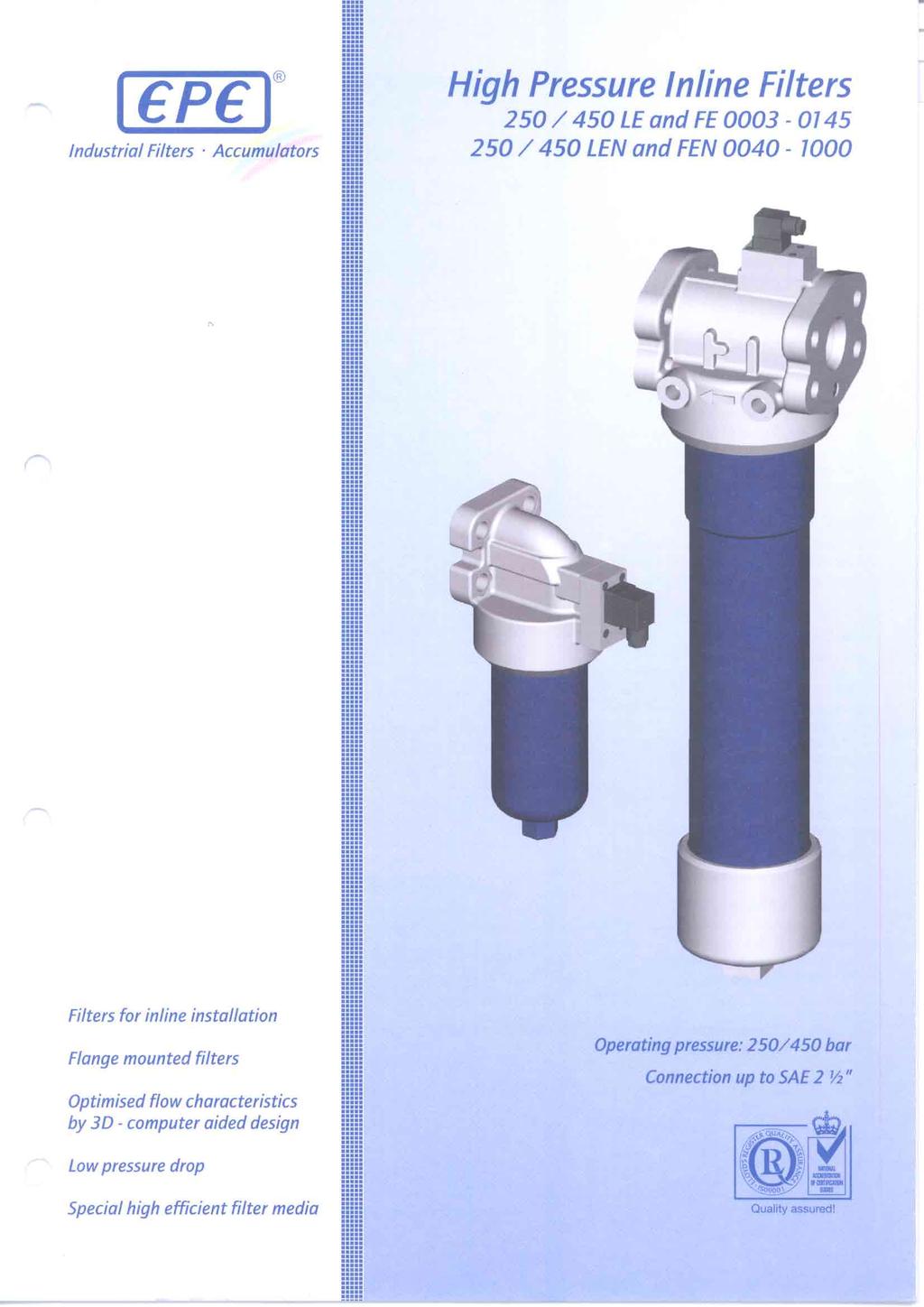
Inline filter. Features RE 51401/ Types 40 FLEN 0160 to 1000; 40 FLE 0045, 0055, 0120 to 0270
 Inline filter RE 5101/08.08 1/10 Types 0 FLEN 0160 to 1000; 0 FLE 005, 0055, 010 to 070 Nominal size according to DIN 550: 0160 to 1000 Nominal size according to BRFS: 005, 0055, 010 to 070 Nominal pressure
Block mounting filter, lateral flange-mounting possible
 Block mounting filter, lateral flange-mounting possible RE 0/.0 Replaces: 0.09 / Types 0/0 FEN 000 to 000; 0/0 FE 000, 00, 008 Nominal sizes according to DIN 0: 000 to 000 Nominal sizes according to BRFS:
Line filter. Features. RE 51400/01.09 Replaces: Types 40/100 LEN 0040 to 0400; 40/100 LE 0003, 0015, 0018
 Line filter RE /.9 Replaces: 8.8 / Types / LEN to ; / LE,, 8 Nominal sizes according to DIN : to Nominal sizes according to BRFS:,, 8 Nominal pressures, bar Connections up to G / Operating temperature
Series RFL In-Line Filter
 APPLICATION Series RFL In-Line Filter Pressures 2 bar Flows to 400 l/min HYDAC RFL In-Line Filters are designed for in-line mounting. These filters can be used in hydraulic, flushing, and for extraction
Low / Medium Pressure Duplex Filter Inline mounting. Type : 40/160-LD/LDN. Filters. Accumulators. Hydraulic Symbol. Technical Data
 Filters. Accumulators Low / Medium Pressure Duplex Filter Inline mounting Type : 0/60LD/LDN Hydraulic Symbol Technical Data Material of Construction Head : GGG50. Bowl : Carbon Steel. Seals : Nitrile /
HIGH PRESSURE FILTERS DF/DFF 1500 Series Inline Filters 6090 psi up to 250 gpm
 HIGH PRESSURE FILTERS DF/DFF 1500 Series Inline Filters 6090 psi up to 250 gpm Hydraulic Symbol DFF FILTER REVERSE FLOW CIRCUIT Bypass Valve Filter Element Pop-up Indicator Features Available in T ported
Replacement cartridge filter
 Replacement cartridge filter RE 426/0. /2 Type 7 SL 0 to 260; 7 SLS 90 to 260; SL 0 to 80 D Size 7 SL: 0 to 260 7 SLS: 90 to 260 SL: 0 to 80 D Nominal pressure 7 and/or bar Port up to G /4, SAE /2 (000
SPIN-ON FILTERS & ELEMENTS
 ABSOLUTE RATED (BETA SPIN ) & NOMINAL RATED SPIN-ON FILTERS & ELEMENTS Single and Twin Element Models Pressures to 20 psi Flows to 120 gpm APPLICATION HYDAC Spin-On Filters are for filtration of hydraulic
PRESSURE FILTERS FOR MODULAR STACKING. Series DF-Z Pressures to 4500 psi Flows to 10 gpm APPLICATION PRODUCT FEATURES FILTER ELEMENTS
 PRESSURE FILERS FOR MODULAR SACKING Series DF-Z Pressures to 4500 psi Flows to 10 gpm APPLICAION DF...Z Pressure filters are designed for modular stacking and can be mounted directly to the component to
50P Series High Pressure Filters
 P Series High Pressure Filters 1 P Series Applications for P series filters Automotive specified equipment Hydrostatic transmission circuits Servo and proportional controls Offshore drilling rigs Mining
10 Hydraulic Filters
 1 Hydraulic Filters Introduction................................... 1-3 HF65 Series................................. 1-9 HF66 Series................................ 1-15 HF67 Series................................
Courtesy of CMA/Flodyne/Hydradyne Motion Control Hydraulic Pneumatic Electrical Mechanical (800)
") Features MF Filters are manufactured with an aluminum head. MF, MFD, MFDS Series Spin-On Filters Choice of NPT, SAE straight thread O-ring boss, BSPP, and SAE 4-bolt flange porting to allow easy installation
Features MF Filters are manufactured with an aluminum head. MF, MFD, MFDS Series Spin-On Filters Choice of NPT, SAE straight thread O-ring boss, BSPP, and SAE 4-bolt flange porting to allow easy installation
Pressure: Max working 280 bar (4000 psi) (acc. to NFPA T ) Burst 840 bar (12200 psi) (acc. to NFPA T )
 (acc. to NFPA T ) Burst 840 bar (12200 psi) (acc. to NFPA T )") HYDRAULIC FILTRATION In line medium pressure filters Technical Information Pressure: Max working 280 bar (4000 psi) (acc. to NFPA T 3.10.5.1) Burst 840 bar (12200 psi) (acc. to NFPA T 3.10.5.1) Housing
HYDRAULIC FILTRATION In line medium pressure filters Technical Information Pressure: Max working 280 bar (4000 psi) (acc. to NFPA T 3.10.5.1) Burst 840 bar (12200 psi) (acc. to NFPA T 3.10.5.1) Housing
MEDIUM PRESSURE FILTERS MFX Series Inline Filters 725 psi up to 35 gpm Hydraulic Symbol
 MFX Series Inline Filters 725 psi up to 35 gpm Hydraulic Symbol A B Features Eco-friendly, cost-effective alternative to spin-on filters Integrated retrofit protection Longer service life of the filter
LOW PRESSURE FILTERS RF Series In-tank / Inline Filters 360 psi up to 400 gpm
 LOW PRESSURE FILTERS RF Series In-tank / Inline Filters 36 psi up to 4 gpm Hydraulic Symbol A D2 Features RF 3 filters are constructed of polyamide plastic. RF 6-33 filters are constructed of aluminum
Low Pressure Filters
 MF, MFD, MFDS Series Spin-On Filters 250 PSI up to 120 GPM Hydraulic Symbol /80/85/160/180 MF 90/95/190/195 A A B B Features MF Filters are manufactured with an aluminum head. Choice of NPT, SAE straight
10 Hydraulic Filters
 1 Hydraulic Filters Introduction.... 1- HF65 Series.... 1-9 HF66 Series.... 1-15 HF67 Series.... 1-21 HF68 Series.... 1-1 Dual Spin-On Assembly.... 1-5 Introduction Hydraulic Filtration Systems Cummins
Series RFLD Duplex In-Line Filter
 APPLICATION Series RFLD Duplex In-Line Filter Welded Pressures to 230 psi Flows to 3900 gpm HYDAC RFLD in-line filters are designed for in-line mounting and are mainly used in continuously operating systems.
FPK 02 AP280. Pressure Line High Pressure Filters In-Line up to 420 bar. Mix&Match to Get What You Need
 FPK 02 AP280 Pressure Line High Pressure Filters In-Line up to 420 bar Mix&Match to Get What You Need Donaldson's Mix&Match system provides the great performance and functional advantages of custom-engineered
NFH Low Pressure Filters
 PPLICTIONS NFH Low Pressure Filters Pressures to 360 psi Flows to 450 gpm Water Removal Capability 4 Ports HYDC NFH In-line Return Filters are designed for use on hydraulic power units, machine tools,
MPD Series. Medium Pressure Duplex
 Medium Pressure Duplex 81 Applications of MPD Circulating Lube Oil Systems Power Generation Control Systems Steel Mill Control Systems Pulp & Paper Control Systems Test Stands Automotive Stamping Presses
MPD Series. Medium Pressure Duplex
 Medium Pressure Duplex 89 Applications of MPD Circulating Lube Oil Systems Power Generation Control Systems Steel Mill Control Systems Pulp & Paper Control Systems Test Stands Automotive Stamping Presses
AGS/MPN Series. Medium Pressure Filters. Global Filtration Technology
 Medium Pressure Filters Global Filtration Technology 63 Features/Applications for Medium Pressure Inline Filters AGS Series Rated Working Pressure 1000 PSI Rated Static Pressure 1500 PSI Flows to 25 GPM
Low Pressure Medium Pressure High Pressure Accessories Off-line Filtration
 Front Donaldson Cover DeliversHeadline Should HYDRAULIC Be Centered SERVICE PARTS & In ACCESSORIES This Color Box GUIDE Low Pressure Medium Pressure High Pressure Accessories Off-line Filtration Donaldson
Pressure: Max working F280 D12x port size 1/2 & 3/4 : 420 bar (6000 psi) Burst F280 D12x port size 1/2 & 3/4 : 1260 bar (18000 psi)
 Burst F280 D12x port size 1/2 & 3/4 : 1260 bar (18000 psi)") HYDRAULIC FILTRATION F8-D1 series In line medium pressure filters Technical Information Housing Pressure: Max working F8 D1x port size 1/ & 3/4 : 4 bar (6 psi) F8 D1x port size 1 : 3 bar (4 psi) F8 D14x:
HYDRAULIC FILTRATION F8-D1 series In line medium pressure filters Technical Information Housing Pressure: Max working F8 D1x port size 1/ & 3/4 : 4 bar (6 psi) F8 D1x port size 1 : 3 bar (4 psi) F8 D14x:
LOW PRESSURE FILTERS MF, MFD, MFDS Series Spin-On Filters 250 PSI up to 120 GPM
 MF, MFD, MFDS Series Spin-On Filters 250 PSI up to 120 GPM Hydraulic Symbol MF 80/85/160/180 MF 90/95/190/195 A A (Standard) (Suction) B B Features MF Filters are manufactured with an aluminum head. Choice
IL8 Series. Medium Pressure Filters
 Medium Pressure Filters Applications for IL8 series filters Lube oil systems Power generation plants Test stands Primary metal equipment Pulp & paper equipment Offshore drilling and oil patch Flushing
Inline Filter RFL. Cast version Volume rates up to 1300 l/min* Pressure range 25/40 bar
 RFL inline filters are designed for inline mounting in hydraulic and lubrication systems. Inline Filter RFL Cast version Volume rates up to 1300 l/min* Pressure range 25/40 bar * For larger flow rates,
LOW PRESSURE FILTERS MF, MFD, MFDS Series Spin-On Filters 250 PSI up to 120 GPM
 LOW PRESSURE FILTERS MF, MFD, MFDS Series Spin-On Filters 250 PSI up to 120 GPM Hydraulic Symbol MF 80/85/160/180 MF 90/95/190/195 A A (Standard) (Suction) B B Features MF Filters are manufactured with
Connection Ports: 3/4 1 1/4 BSP (other thread options on request)
") HYDRAULIC FILTRATION Medium pressure, in line spin-on filters Technical Information Pressure: Max working (acc. to NFPA T 3.10.17): FA-4-1x: 34,5 bar (500 psi) FA-4-21: 24 bar (348 psi) Burst (acc. to
HYDRAULIC FILTRATION Medium pressure, in line spin-on filters Technical Information Pressure: Max working (acc. to NFPA T 3.10.17): FA-4-1x: 34,5 bar (500 psi) FA-4-21: 24 bar (348 psi) Burst (acc. to
LF/LFM - Low Pressure High Flow Assemblies LF flow rate to 560 lpm, 150 gpm / LFM flow rate to lpm, 4500 gpm.
 HY-PRO FILTRATION LF/LFM - Low Pressure High Flow Assemblies LF flow rate to 560 lpm, 150 gpm / LFM flow rate to 16875 lpm, 4500 gpm Features, Benefits, Advantages Carbon steel construction standard (304
Inline Filter RFLD. Change-Over. Cast Version Flow Rates up to 1300 l/min* Pressure Range 25/40/64 bar With Ball Change-Over Valve E /01.
 Change-Over Inline Filter RFLD Cast Version Flow Rates up to 3 l/min* Pressure Range 25/4/64 bar With Ball Change-Over Valve * For higher flow rates, please refer to brochure RFLD Welded Version E 7.9.2/.4
15P/30P Series High Pressure Filters
 1P/P Series High Pressure Filters 124 1P/P Series Applications Saw mills Aircraft ground support equipment Asphalt pavers Hydraulic fan drives Power steering circuits Waste trucks Cement trucks Servo control
MPD Series Medium Pressure Filters
 Medium Pressure Filters 113 Applications - Circulating Lube Oil Systems - Power Generation Control Systems - Steel Mill Control Systems - Pulp & Paper Control Systems - Test Stands - Automotive Stamping
Low & High Pressure ProGuard Filters
 56 ±.2 (2.2 ±.5) ø13 +1.5 (5.12 +.6 ) INDICATOR PLUG 193 (7.6) 14 (5.51) 95 (3.74) LABEL 1 5/8-12UNF IN. OR G 1 1/4 PORT SAE-2 PORT 2 PL'S 196 (7.72) 58 (2.28) ø13.2 (5.13) L (4 Low & High Pressure ProGuard
15/40/80CN Series. Medium Pressure Filters
 //8CN Series Medium Pressure Filters 7 //8CN Series Applications for CN series Filters Compressor Lube Oil Off-line Filter Loops Machine Tools (Automotive Standard) Hydrostatic Drive Charge Pumps Mobile
World Pressure Filters. A New Standard in 7,000 psi Pressure Filters
 World Pressure Filters A New Standard in 7, psi Pressure Filters 12 WPF Series Applications Together we can the environment. Preserve Minimize waste and promote energy efficiency. worldwide Achieve filtration
Connection Ports: 1/2 1 1/2 BSP (other thread options on request) aluminium alloy NBR (FKM on request)
 aluminium alloy NBR (FKM on request)") HYDRAULIC FILTRATION In line medium pressure filters Technical Information Pressure: Max working (acc. to NFPA T 3.1.5.1): F1-XD4/63/1: 1 bar (15 psi) F1-XD16/25/4: 8 bar (12 psi) Housing Burst (acc. to
HYDRAULIC FILTRATION In line medium pressure filters Technical Information Pressure: Max working (acc. to NFPA T 3.1.5.1): F1-XD4/63/1: 1 bar (15 psi) F1-XD16/25/4: 8 bar (12 psi) Housing Burst (acc. to
Stainless Steel Pressure Filters
 Stainless Steel Pressure Filters Inline Filters up to 26,000 PSIG up to 35 GPM Description Process Filtration MPSSF / HPSSF/ ACSSF Series The pressure filters consist of two main sections: the filter head
Filtrec elements are tested according to ISO 2941, ISO 2942 and ISO 23181
 Common HYDRAULIC FILTRATION Side wall mounting suction filters Technical Information Connection Ports: 1-1 1/4-1 1/2 BSP (other thread options on request) 1 1/2 SAE J518-3000/M12 Housing Materials: Cover:
By-pass: 1,7 bar (24.6 psi) setting N.B. Cartridge with integrated bypass valve and antidrainback membrane
 setting N.B. Cartridge with integrated bypass valve and antidrainback membrane") HYDRAULIC FILTRATION Spin-on, tank top return filters Technical Information Pressure: Max working 12 bar (175 psi) (acc. to NFPA T 3.10.17) Burst 20 bar (290 psi) (acc. to NFPA T 3.10.17) Connection Ports:
HYDRAULIC FILTRATION Spin-on, tank top return filters Technical Information Pressure: Max working 12 bar (175 psi) (acc. to NFPA T 3.10.17) Burst 20 bar (290 psi) (acc. to NFPA T 3.10.17) Connection Ports:
IL8 Series. Medium Pressure Filters
 Medium Pressure Filters 6 Applications for IL8 series filters Lube oil systems Power generation plants Test stands Primary metal equipment Pulp & paper equipment Offshore drilling and oil patch Flushing
World Pressure Filters A New Standard in 7,000 psi Pressure Filters
 World Pressure Filters A New Standard in 7, psi Pressure Filters 12 Applications Together we can Preserve the environment. Minimize waste and promote energy efficiency. Achieve worldwide filtration solutions.
A complete line of pressure differential visual and electrical indicators are available with this series of filters.
 D e s c r i p t i o n FHB series filters are designed for pressure line applications where manifold mounting is a specific requirement. The manifold type filters are designed to integrate onto manifold
Pressure: Max working 8 bar (116 psi) (acc. to NFPA T ) Burst 16 bar (232 psi) (acc. to NFPA T ) Buna-N (FKM on request)
 (acc. to NFPA T ) Burst 16 bar (232 psi) (acc. to NFPA T ) Buna-N (FKM on request)") HYDRAULIC FILTRATION Return filters, tank top mounting, inside-to-outside filtration Technical Information Pressure: Max working 8 bar (116 psi) (acc. to NFPA T 3.10.5.1) Burst 16 bar (232 psi) (acc. to
HYDRAULIC FILTRATION Return filters, tank top mounting, inside-to-outside filtration Technical Information Pressure: Max working 8 bar (116 psi) (acc. to NFPA T 3.10.5.1) Burst 16 bar (232 psi) (acc. to
World Pressure Filters A new standard in 7,000 psi pressure filters
 World Pressure Filters A new standard in 7, psi pressure filters Applications Together we can Preserve the environment. Minimize waste and promote energy efficiency. Achieve worldwide filtration solutions.
Pressure: Max working 110 bar (1600 psi) (acc. to NFPA T ) Burst 330 bar (4800 psi) (acc. to NFPA T ) Wire mesh µm
 (acc. to NFPA T ) Burst 330 bar (4800 psi) (acc. to NFPA T ) Wire mesh µm") HYDRAULIC FILTRATION In line medium pressure filters Technical Information Pressure: Max working 110 bar (1600 psi) (acc. to NFPA T 3.10.5.1) Burst 330 bar (4800 psi) (acc. to NFPA T 3.10.5.1) Housing
HYDRAULIC FILTRATION In line medium pressure filters Technical Information Pressure: Max working 110 bar (1600 psi) (acc. to NFPA T 3.10.5.1) Burst 330 bar (4800 psi) (acc. to NFPA T 3.10.5.1) Housing
NFHD Modular Duplex Filter System Pressures to 360 psi Flows to 450 gpm 4 Ports
 NFHD Modular Duplex Filter System Pressures to 360 psi Flows to 450 gpm 4 Ports PPLICTIONS HYDC NFHD Return Line Filters are designed for use on hydraulic power units, machine tools, plastics injection
Inline filter with filter element according to DIN 24550
 Inline filter with filter element according to DIN 24550 RE 51421/07.11 Replaces: 12.10 1/16 Type 245LEN0040 to 400; 245LE0130, 0150 Size according to DIN 24550: 0040 to 0400 Additional sizes: 0130, 0150
15/40/80CN Series Coreless Medium Pressure Filters
 //8CN Series Coreless Medium Pressure Filters 89 //8CN Series Applications Compressor Lube Oil Off-line Filter Loops Machine Tools (Automotive Standard) Hydrostatic Drive Charge Pumps Mobile Equipment
High Pressure Filters. 15P/30P Series. MAX 200 I/min bar. High pressure filters
 P/3P Series MAX 2 I/min - 27 bar 9 High pressure filters P/3P Series Features & Benefits Features Compact aluminium housing Two head sizes and two bowl lengths Large ports and wide flow paths Microglass
Oil Solutions. GA/BGAH Series Medium Pressure Filters. Global Filtration Technology. Filtration.
 Oil Solutions Medium Pressure Filters Filtration Global Filtration Technology www.oilsolutions.com.au Features/Applications for Medium Pressure Inline Filters GA Series Pressures to 750 PSI Flows to 100
VacuClean Systematic Oil Treatment Patented
 Industrial Filters Accumulators VacuClean Systematic Oil Treatment Patented All-In-One system for cleaning and reconditioning of hydraulic oils and lubricants in the bypass flow Size Mobile: 20, 50, 80
Line filter with filter element according to DIN 24550
 Line filter with filter element according to DIN 2455 RE 51423/9.12 Replaces: 7.1 1/2 Type 445LEN4 to 1 Size according to DIN 2455: 4 to 1 Nominal pressure: 45 bar [6527 psi] Connection up to G 1 1/2;
Inline filter with filter element according to DIN 24550
 Inline filter with filter element according to DIN 24550 RE 51422/07.11 Replaces: 12.10 1/18 Type 350LEN0040 to 1000; 350LE0130, 0150 Size according to DIN 24550: 0040 to 1000 Additional sizes: 0130, 0150
Accessories. Service, In-Line and Reservoir. Accessories ACCESSORIES
 Accessories Donaldson offers an extensive line of accessories for hydraulic circuits, lines and reservoirs that will help you maintain proper ISO cleanliness levels. Accessories Service, In-Line and Reservoir
12CS/50CS Series. Coreless Spin-on Filters
 12CS/5CS Series Coreless Spin-on Filters 65 12CS/5CS Series Applications Together we can Preserve the environment. Minimize waste and promote energy efficiency. Achieve worldwide filtration solutions.
12CS Series. Coreless Spin-on Filter Max. 75 l/min - 35 bar. Environmentally friendly alternative for spin-in filtration.
 12CS Series Coreless Spin-on Filter Max. 7 l/min - 3 bar Environmentally friendly alternative for spin-in filtration Lightweight, non-metallic element that can be incinerated The 12CS Series features a
Pressure: Max working 8 bar (116 psi) (acc. to NFPA T ) Burst 16 bar (232 psi) (acc. to NFPA T )
 (acc. to NFPA T ) Burst 16 bar (232 psi) (acc. to NFPA T )") HYDRAULIC FILTRATION Tank top return filters Technical Information Pressure: Max working 8 bar (116 psi) (acc. to NFPA T 3.1..1) Burst 16 bar (232 psi) (acc. to NFPA T 3.1..1) Housing Connection Ports:
HYDRAULIC FILTRATION Tank top return filters Technical Information Pressure: Max working 8 bar (116 psi) (acc. to NFPA T 3.1..1) Burst 16 bar (232 psi) (acc. to NFPA T 3.1..1) Housing Connection Ports:
WITH P INDICATOR OPTION INDICATOR POSITION # INDICATOR POSITION # P3000G04=4.0" P3000G08=7.8"
 D6 P3 SERIES WITH P OPTIO Flows Up To: Port Sizes: Max. Operating Pressure: Application: 3 GPM (114 L/MI) 1 1/16-12 U (SAE-12) 3, PSI (27 BAR) Inline Filtration, External Charge Pump Filtration, High Shock
LOW PRESSURE FILTERS RFM Series In-Tank Return Line Filters 145 psi up to 224 gpm
 LOW PRESSURE FILTERS RFM Series In-Tank Return Line Filters 145 psi up to 4 gpm Technical Specifications Mounting Method 75/9/15/165/185 mounting holes - filter housing D5 Features The compact and lightweight
Type 400LDN0040 to 1000; 400LD0130, 0150
 Duplex filter with filter element according to DIN 24550 Type 400LDN0040 to 1000; 400LD0130, 0150 RE 51429 Edition: 2012-07 Replaces: 02.11 Size according to DIN 24550: 0040 to 1000 Additional sizes: 0130,
Return Line Filter RF
 HYDAC return line filters type RF are designed to be mounted directly on tank tops. Inline mounting is also possible. Return Line Filter RF Flow rates up to 5, l/min Pressure range up to 25 bar Material:
Inline Filter MFM. Flow rates up to 100 l/min Pressure range up to 280 bar Material: EN-GJS / steel E /01.04
 Inline Filter MFM Flow rates up to 100 l/min Pressure range up to 280 bar Material: EN-GJS 400-15 / steel 1. TECHNICAL SPECIFICATIONS 1.1. FILTER HOUSING Construction The inline filter consists of a filter
Moduflow. ILP and RFP Low Pressure Filters. Series
 Moduflow ILP and RFP Low Pressure Filters Series 27 Applications for Moduflow Filters Power Unit Fabrication Off-line Filter Loops Mobile Equipment The Moduflow filter is widely considered the most versatile
Connection Ports: 3/4 1 1/4 BSP (other thread options on request) aluminium alloy NBR (FKM on request)
 aluminium alloy NBR (FKM on request)") HYDRAULIC FILTRATION F4-DMD series In line medium pressure filters Technical Information Pressure: Max working (acc. to NFPA T 3.1..1): F4-DMD/8/11: 7 bar (11 psi) F4-DMD1/3/4: 4 bar (8 psi) Housing Burst
HYDRAULIC FILTRATION F4-DMD series In line medium pressure filters Technical Information Pressure: Max working (acc. to NFPA T 3.1..1): F4-DMD/8/11: 7 bar (11 psi) F4-DMD1/3/4: 4 bar (8 psi) Housing Burst
Moduflow Series IL2/RF2/CF2 Low Pressure Filters
 IL/RF/CF Low Pressure Filters 35 Applications for Moduflow Filters Power Unit Fabrication Off-line Filter Loops Mobile Equipment The Moduflow filter is widely considered the most versatile filter available
Inline Filters NF. Flow rates up to 3,500 l/min Pressure range 25 bar Material: Aluminium / Aluminium-Cast Iron
 NF filters are designed for inline mounting and as tank-top mounted return line filters. These filters can also be used on filling, flushing and off-line units. Inline Filters NF Flow rates up to 3,500
Low Pressure Filters
 In-Tank Return Line Filters PSI up to GPM Hydraulic Symbol: INLET INLET Bypass Valve Pop-up Breather Bypass Valve Pop-up TANK OUTLET TANK OUTLET TANK OUTLET Features: The compact and lightweight design
Block mounting filter, for vertical flange-mounting
 Block mounting filter, for vertical flange-mounting RE 51417/12.1 Replaces: 7.1 1/18 Type 45PBFN4 to 1; 45PBF13, 15 Size according to DIN 2455: 4 to 1 Additional sizes: 13, 15 Nominal pressure 45 bar [653
Pressure Filters DF...M A / DF...Q E DF...MHA / DF...MHE Flow rates up to 500 l/min Pressure range up to 315 bar Material: SG Iron/ADI, Steel
 Manifold Mounted, Rear Flanged Pressure Filters DF...M A / DF...Q E DF...MHA / DF...MHE Flow rates up to 5 l/min Pressure range up to 35 bar Material: SG Iron/ADI, Steel . DESCRIPTION.. FILTER HOUSING
THE IMPORTANCE OF AN EFFICIENT FILTRATION
 In line high pressure filters HF 745 / HF 748 series THE IMPORTANCE OF AN EFFICIENT FILTRATION The main cause of anomalies in hydraulic systems has to be attributed to the presence of contaminants in the
Pressure: Max working 420 bar (6000 psi) (acc. to NFPA T ) Burst 1260 bar (18300 psi) (acc. to NFPA T )
 (acc. to NFPA T ) Burst 1260 bar (18300 psi) (acc. to NFPA T )") HYDRULIC FILTRTION In line high pressure filters Technical Information Pressure: Max working 420 bar (6000 psi) (acc. to NFP T 3.10.5.1) Burst 1260 bar (18300 psi) (acc. to NFP T 3.10.5.1) Housing Connection
HYDRULIC FILTRTION In line high pressure filters Technical Information Pressure: Max working 420 bar (6000 psi) (acc. to NFP T 3.10.5.1) Burst 1260 bar (18300 psi) (acc. to NFP T 3.10.5.1) Housing Connection
In line high pressure filters. HF 735 series
 In line high pressure filters HF 735 series THE IMPORTANCE OF AN EFFICIENT FILTRATION The main cause of anomalies in hydraulic systems has to be attributed to the presence of contaminants in the fluid.
FCL Filter Cart Flow rate up to 22 gpm (82 lpm)
") click here to return to website FCL Filter Cart Flow rate up to 22 gpm (82 lpm) Ideal for high viscosity Lubrication and hydraulic oils (ISOVG22 ~ ISOVG320) Filter new fluids during transfer and replenishment
click here to return to website FCL Filter Cart Flow rate up to 22 gpm (82 lpm) Ideal for high viscosity Lubrication and hydraulic oils (ISOVG22 ~ ISOVG320) Filter new fluids during transfer and replenishment
RF4 Series. Return Line Filters
 RF Series Return Line Filters 7 RF Series Applications for RF Filters Mobile Equipment Mining Equipment Industrial Power Units Automotive Specified Equipment The RF is a rugged, industry proven filter
HYDRAULIC AND LUBE OIL FILTERS RFM Series
 HYDRAULIC AND LUBE OIL FILTERS RFM Series Low Pressure In-Tank Return Line Filters psi up to gpm Technical Details Mounting Method 7/9///8 mounting holes - filter housing Features The compact and lightweight
Spin-on elements. Type 80, 81 and 82. Contents. Features. RE Edition:
 Spin-on elements Type 80, 81 and 82 RE 51478 Edition: 2015-06 Sizes according to according to Bosch Rexroth standard: 30 to 130 Pressure differential resistance up to 5 bar [72.5 psi] Filter rating: 1
LF(M) High Viscosity Filter Assemblies. hyprofiltration.com/lf
 High Viscosity Filter Assemblies. hyprofiltration.com/lf") LF(M) High Viscosity Filter Assemblies Low pressure filter assemblies optimized for high flow hydraulic, high viscosity lube and heavily contaminated fuel applications. Max Operating Pressure: 150 psi
LF(M) High Viscosity Filter Assemblies Low pressure filter assemblies optimized for high flow hydraulic, high viscosity lube and heavily contaminated fuel applications. Max Operating Pressure: 150 psi
12CS/50CS Series Coreless Medium Pressure Filters
 12CS/5CS Series Coreless Medium Pressure Filters 65 12CS/5CS Series Applications Together we can Preserve the environment. Minimize waste and promote energy efficiency. Achieve worldwide filtration solutions.
Inline filter with filter element according to DIN 24550
 Inline filter with filter element according to DIN 24550 RE 51448/06.11 Replaces: RE 51400 1/18 Type 110LEN0040 to 0400; 110LE0130, 0150 Size according to DIN 24550: 0040 to 0400 Additional sizes: 0130,