A complete line of pressure differential visual and electrical indicators are available with this series of filters.
|
|
|
- Caroline Bradley
- 5 years ago
- Views:
Transcription
1


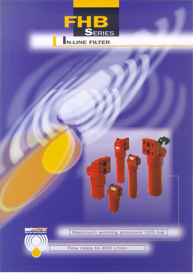
2 D e s c r i p t i o n FHB series filters are designed for pressure line applications where manifold mounting is a specific requirement. The manifold type filters are designed to integrate onto manifold valve systems to provide a compact low pressure loss and leak free installation. Continued research and development on both the filter bodies and the filter elements has resulted in a product line with excellent pressure drop characteristics combined with a high filtration efficiency. A complete line of pressure differential visual and electrical indicators are available with this series of filters. FHB series filters are available with Reverse Flow Valve. FHB series filters within this range are suitable for flow rates to 400 l/min. See page. FHB series are suitable for industrial machinery steel and process application. ELECTRICAL DIFFERENTIAL INDICATORS VISUAL-ELECTRICAL New absolute filter elements independently tested in the following Institutes: VISUAL INDICATOR OPTIONS CAST IRON HEAD BYPASS VALVE O-RING + RETAINING RING UNI EN ISO 9001 N 07/98 CAPTIVE O-RING HIGH EFFICIENCY ELEMENT WITH HIGH DIRT HOLDING CAPACITY STEEL BOWL FHB 0500/6.99/UK Sost..98/UK 2
 Inner support tube")
3 MP Filtri - Filtration technology Filter element: Filter element material A Series Inorganic microfibre External support media External wire mesh Element material Absolute filtration New material: New improved ß 200 filter elements with greater efficiency and increased dirt holding capacity Filtering area Filter elements N - P 20 bar End caps: Steel (Thermal treatment) Inner support tube Internal wire mesh Microfibre filtration media Internal support media A Series Inorganic microfibre with acrilic support Filter elements ß 2 (50%) Support tube: Steel (Thermal treatment) Dimensions for ß(µm) values ß 20 (95%) ß 75 (98,7%) ß 200 (99,5%) Support frames: Coated wire cloth Contamination retention as per ISO 4572: Multi-pass test. Filtration ratios ß2 ß10 ß20 _ 2 2,4 20 > > _ 4,6 6 8 > > ,8 10 1,5 200 > _ > 1,5 > 5 7 N.B. Other materials giving different degrees of filtration are available on request. Type HP / / Type HP MP Filter elements - Conform to the following ISO standards ISO Verification of collapse/burst resistance. ISO Verification of fabrication integrity and determination of the first bubble point. ISO Verification of material compatibility with fluids. ISO 72 - Method for end load test. ISO Verification of flow fatigue characteristics. ISO Evaluation of pressure drop versus flow characteristics. ISO Multi-pass method for evaluating filtration performance P (bar) Values in cm Filtering area / Filter elements / H - P 210 bar Values in cm Element material Nominal filtration M Series T Series Filtering area Filter elements N - P 20 bar Filtering area Filter elements T - P 80 bar Square wire mesh (filtration degree is defined in microns by the maximum diameter of a sphere corresponding to the mesh size) M10 M25 M60 Triangular stainless steel wire mesh Type HP Values in cm 2 Type HP /T Values in cm 2
4 MP Filtri - Specification Filter body: Materials Head Cast iron (Thermal treatment) Bowl Steel (Thermal treatment) Bypass valve Brass Reverse flow (Only for 15/20 series) Steel Working temperature Pressure filter body Seals A Series: Nitrile (Buna-N) V Series: Viton Maximum working pressure up to 20 bar Test pressure: 420 bar Minimum burst pressure: 840 bar Indicator Brass (with viton seals) From -25 to +110 C For temperatures outside this range, please consult our Sales Network Organization Fatigue test: a filter body subjected to pressure impulses from 0 to 20 bar will withstand cycles Collapse pressure filter elements N Series: 20 bar Bypass valve Calibration pressure Compatibility with fluids Bypass valve, differential opening pressure: Filter head and bowls compatible for use with: mineral oils (types HH-HL-HM-HR-HV-HG as per ISO 674/4) water-based emulsions (types HFAE-HFAS as per ISO 674/4) synthetic fluids (types HS-HFDR-HFDS-HFDU as per ISO 674/4) water-glycol (types HFC as per ISO 674/4) H Series: H Series: B: 6 bar ± 10% 80 bar 210 bar Filter elements As per ISO 294; suitable for mineral oils (types HH-HL-HM-HR-HV-HG as per ISO 674/4) and synthetic fluids (A and M series only) (types HS-HFDR-HFDS-HFDU as per ISO 674/4) For water-based emulsions (types HFAE-HFAS as per ISO 674/4) and fluids other than those mentioned, please consult our Sales Network Organization. Types of indicators Visual indicator Electrical indicator Visual-electrical indicator Seals A Series Nitrile (Buna-N) compatible with mineral oils (types HH-HL-HM-HR-HV-HG as per ISO 674/4) (Complete with Viton seals) Description: FHB series filters are fitted with indicators switching at a pressure of 5 bar ± 10% (for N elements series) 7 bar ± 10% (for H and T elements series) 10 bar ± 10% (for H and T elements series) With bypass 5 bar setting: V7 Series With bypass 5 bar setting: N7 Series With bypass 5 bar setting: E7-K7 Series Without bypass 7 bar setting: V8 Series Without bypass 7 bar setting: N8 Series Without bypass 7 bar setting: E8-K8 Series For K visual-electrical indicator, specify the voltage (f.i. K71 = LED 24 volt) water-based emulsions (types HFAE-HFAS as per ISO 674/a) water - glycol (types HFC as per ISO 674/4) V Series Viton compatible with synthetic fluids (types HS-HFDR-HFDS-HFDU as per ISO 674/4) J series - Thermal lockout Electrical Indicators available - contact MP Filtri Without bypass 10 bar setting: V9 Series Without bypass 10 bar setting: N9 Series Without bypass 10 bar setting: E9-K9 Series { 1-24 Volt Volt - 20 Volt 4
")
 5 5 5 0,5")


5 MP Filtri - Specification K - E - N Series Supply voltage (50/60 Hz) (V) Vca 5 Vca 250 Vcc 0 Vcc 5 Vcc 250 Resistive load (A) ,5 0,25 Inductive load (A) 2 2 0,0 0,0 CONNECTOR DIN 40 ELECTRICAL CONNECTION E - N SERIES N.C. N.O. ELECTRICAL CONNECTION K SERIES N.C. N.O. Visual V series Electrical N series Visual - Electrical K series Visual - Electrical E series,5 Led Ø16 G1/2 Ø16 G1/2 Ø16 G1/2 Ø16 G1/2 5
6 Selection & installation information Filter Elements types A Series Absolute inorganic microfibre filtration media, available in, 6, 10 and 25 micron Example -,, or M Series Metal mesh media, available in 10, 25 and 60 micron Example - M10, M25 or M60 T Series Triangular stainless steel mesh media, available in 10, 25 micron Example -, T25 Please refer to individual pressure drop curves to obtain filter assembly pressure drop information The following filter sizing recommendations are based using a mineral oil fluid at 0 mm 2 /s (cst), with a maximum filter assembly (housing and filter element) pressure drop of 25% of the filter condition indicator (1.25 bar) FHB 0 SERIES Ø15 Ø Indicator port 42 FHB 0 V Filter assembly Flow rate l/min N series Flow rate l/min H-T series Bowl length Port size BSP/NPT/SAE Weight kg 1, H 5 25 N ,6 Led Ø 68 K ,0 Flow rates with 0 mm 2 /s fluid viscosity Weight including filter element E Lengths,5 Type H FRONT VIEW Housing pressure drop curve FHB ,75 N 2 holes Ø = = 67 0,
7 Selection & installation information Please refer to individual pressure drop curves to obtain filter assembly pressure drop information The following filter sizing recommendations are based using a mineral oil fluid at 0 mm 2 /s (cst), with a maximum filter assembly (housing and filter element) pressure drop of 25% of the filter condition indicator (1.25 bar) FHB 15 SERIES Ø20 Ø Indicator port 42 FHB 15 V Filter assembly Flow rate l/min N series Flow rate l/min H-T series Bowl length Port size BSP/NPT/SAE Weight kg 1 6,7 2 8, H 180 N Flow rates with 0 mm 2 /s fluid viscosity Weight including filter element Led Lengths Type H 5 Ø 80 K E,5 76 FRONT VIEW Housing pressure drop curve FHB , N 4 holes Ø 18 0,
8 Selection & installation information Please refer to individual pressure drop curves to obtain filter assembly pressure drop information The following filter sizing recommendations are based using a mineral oil fluid at 0 mm 2 /s (cst), with a maximum filter assembly (housing and filter element) pressure drop of 25% of the filter condition indicator (1.25 bar) FHB 20 SERIES 150 H Ø2 Ø Ø 105 Indicator port A/F FHB 20 Led,5 V N K E Filter assembly Flow rate l/min N series Flow rate l/min H-T series Bowl length Port size BSP/NPT/SAE Weight kg 1 1, ,0 21,0 24,0 76 Flow rates with 0 mm 2 /s fluid viscosity Weight including filter element Lengths FRONT VIEW Only for FHB 20-4 Type H N 4 holes Ø Housing pressure drop curve FHB 20 0,75 0,
9 Pressure drop information General Pressure drop versus flow rate curve information for both housing and filter elements is in accordance with ISO 968 Filter assembly pressure drop - p Total = p Housing + p Filter element Housing pressure drop - The housing pressure drop is proportional to the fluid density Filter element pressure drop - Filter element pressure drop is proportional to kinematic viscosity therefore always check the fluid operating temperature and fluid type to obtain the working viscosity according to the following formula: p 1 Filter element = (working viscosity/brochure viscosity) x p filter element Brochure viscosity 0 mm 2 /s (cst) Selection : Customer requires a 90 l/min filter assembly Mineral oil fluid: ISO VG 46 (46 mm 2 /s (cst) at 40 C) - 10 micron absolute filtration Housing pressure drop - FHB 15-2 with 90 l/min p = 0.2 bar (see curve on page 7) Filter assembly sizing example Filter element pressure drop (brochure viscosity) - HP 15-2AN with 90 l/min p = 0.55 bar (see curve on page 10) Filter element pressure drop (working viscosity) - With 46 mm 2 /s (cst) p 1 = 0.55 x ( 46/0 ) = 0.85 bar Filter assembly pressure drop p Total = p Housing + p 1 Filter element = = 1.05 bar{ Acceptable pressure drop value as per our recommendations Bypass valves pressure drop The curves were obtained using a mineral oil with a density of 0,86 kg/dm. The p varies proportionally to the density. FHB 0 16 FHB FHB Reverse flow valves pressure drop The curves were obtained using a mineral oil with a density of 0,86 kg/dm. The p varies proportionally to the density. 0,75 FHB 15 0,75 FHB 20 0,25 0,
10 Filter elements - N - P 20bar The curves were obtained using a mineral oil with a kinematic viscosity of 0 mm 2 /s (cst). The p varies proportionally to the fluid kinematic viscosity. For the metal filter elements curves (M series), please consult our Sales and Network Organization HP 0-1 A...N HP 0-2 A...N HP 0- A...N HP 15-1 A...N HP 15-2 A...N HP 20-1 A...N HP 20-2 A...N HP 20- A...N HP 20-4 A...N
11 Filter elements - H - P 210bar The curves were obtained using a mineral oil with a kinematic viscosity of 0 mm 2 /s (cst). The p varies proportionally to the fluid kinematic viscosity. HP 0-1 A...H HP 0-2 A...H HP 0- A...H HP 15-1 A...H HP 15-2 A...H HP 20-1 A...H HP 20-2 A...H HP 20- A...H HP 20-4 A...H
12 International standards for contamination fluid control CONTAMINATION CODES ISO 4406 CORRESPONDENT CODES NAS 16 RECOMMENDED FILTRATION DEGREE TYPICAL APPLICATIONS 5 µm 15 µm ßx High precision and laboratory servo-systems Robotic and servo-systems Very sensitive systems where a high degree of reliability is required General equipment of limited reliability Low - pressure equipment not in continuos service Reverse flow valve - Drawing FHB 15 - FHB 20 SERIES OUT IN 1) 2) ) 4) ZERO FLOW FLOW BYPASS REVERSE FLOW
13 Ordering information FHB F Nominal sizes Bowl lengths FHB 0 = 1, 2, FHB 15 = 1, 2 FHB 20 = 1, 2,, 4 Filter condition indicator S With threaded hole only T2 With plug V7 Visual 5 bar V8 Visual 7 bar V9 Visual 10 bar N7 Electrical 5 bar N8 Electrical 7 bar N9 Electrical 10 bar E7 Visual - electrical 5 bar E8 Visual - electrical 7 bar E9 Visual - electrical 10 bar K7 Visual - electrical 5 bar K8 Visual - electrical 7 bar K9 Visual - electrical 10 bar 1-24 Volt Volt { - 20 Volt For K visual-electrical indicator, specify the voltage (f.i. K71 = LED 24 volt) S B W R Integral bypass valve Without bypass With bypass With reverse flow With reverse flow + bypass ( Not available ) for FHB 0 Collapse pressure series N 20 bar T 80 bar H 210 bar A V Nitrile (Buna-N) Viton Seals M10 M25 M60 T25 Filter elements Inorganic microfibre Bx 200 Square wire mesh Stainless steel wire mesh HP Replacement element MP Filtri - Filtration products will only be guaranteed if original MP Filtri replacement elements and spares are used Data hold in this pubblication are given only for indicative purposes. MP Filtri reserves to introduce modifications to describe items in every moment either for technical or commercial reasons. Copyright reserved. 1
SPIN-ON FILTER - LOW PRESSURE LINE
 SERIES MSH SPIN-ON FILTER - LOW PRESSURE LINE Maximum working pressure 5 psi Flow rate to 8 GPM D e s c r i p t i o n MSH working pressure of 5 psi, with a peak pressure This filter MSH series utilises
A complete line of pressure differential visual and electrical indicators are available with this series of filters.
 D e s c r i p t i o n FHP series filters are designed for high pressure line applications and are suitable for in-line installation. Continued research and development on both the filter bodies and the
MPS/MST SERIES SPIN - ON FILTER SUCTION - RETURN. Maximum working pressure 12 bar. Flow rates to 300 l/min
 MPS/MST SERIES SPIN - ON FILTER SUCTION - RETURN Maximum working pressure 12 bar Flow rates to 3 l/min D e s c r i p t i o n MPS/MST The spin-on filter series is a complete product range suitable, for
D e s c r i p t i o n
 D e s c r i p t i o n 250 The SF2 series suction filter are designed for reservoir side-wall applications. This completely new design of filter allows the filter within the filter preventing oil loss from
D e s c r i p t i o n
 e s c r i p t i o n MPH and MPI series filters are designed for returnline applications and provide various installation applications. The filters are installed semiimmersed (MPH) or totally immersed into
OUT. The SF2 series suction filter are designed for reservoir side-wall applications. This completely new design of filter allows the filter
 D e s c r i p t i o n 250 The SF2 series suction filter are designed for reservoir side-wall applications. This completely new design of filter allows the filter within the filter preventing oil loss from
MPF filters within this range are suitable for flow rates up to 750 l/min.
 D e s c r i p t i o n MPF series filters are designed for return lines, and are installed semi-immersed in a reservoir. Continued Research & Development on both the filter bodies and the filter elements
SERIES SF2-250 SUCTION FILTER. Flow rate to 45 gpm
 SERIES SF2-250 SUCTION FILTER Flow rate to 45 gpm D e s c r i p t i o n 250 The SF2 series suction filter are designed for reservoir side-wall applications. This completely new design of filter allows
FMP IN-LINE FILTER SERIES. Maximum working pressure 250 bar. Flow rate to 500 l/min
 INLIN FILTR Maximum working pressure 0 bar Flow rate to 00 l/min R.F. Filter Symbol without bypass Filter Symbol with Reverse Flow R.F. Filter Symbol with bypass Filter Symbol with bypass & Reverse Flow
SERIES SF2-500 SUCTION FILTER. Flow rates to 225 gpm
 SERIES SF2-5 SUTION FILTER Flow rates to 225 gpm D e s c r i p t i o n 5 The SF2 series are designed for reservoir side-wall mounting applications, suitable for flow rates to 225 gpm and filtration from
In line high pressure filters. HF 735 series
 In line high pressure filters HF 735 series THE IMPORTANCE OF AN EFFICIENT FILTRATION The main cause of anomalies in hydraulic systems has to be attributed to the presence of contaminants in the fluid.
In line high pressure filters. HF 725 series
 In line high pressure filters HF 725 series THE IMPORTANCE OF AN EFFICIENT FILTRATION The main cause of anomalies in hydraulic systems has to be attributed to the presence of contaminants in the fluid.
THE IMPORTANCE OF AN EFFICIENT FILTRATION
 In line high pressure filters HF 745 / HF 748 series THE IMPORTANCE OF AN EFFICIENT FILTRATION The main cause of anomalies in hydraulic systems has to be attributed to the presence of contaminants in the
FMM bar. Working pressure. Style T. Style D. Style S. Style B D.I. D.I. D.I. D.I.
 30 FMM 050 SRIS FMM 050 Working pressure 0 bar Style S Style Style T Style D 3 3 Technical data Filter body (Materials) Head: Cast iron (chemical heat treatment) Housing: Steel (chemical heat treatment)
Inline Filter MFM. Flow rates up to 100 l/min Pressure range up to 280 bar Material: EN-GJS / steel E /01.04
 Inline Filter MFM Flow rates up to 100 l/min Pressure range up to 280 bar Material: EN-GJS 400-15 / steel 1. TECHNICAL SPECIFICATIONS 1.1. FILTER HOUSING Construction The inline filter consists of a filter
SERIES FRI. Maximum working pressure 20 bar Flow rate to 1200 l/min. s.p.a
 New Headquarters : MP FILTRI S.p.. Italy Via 1 Maggio, n. 3 Pessano con Bornago (Milano) Italy Tel. +39./973.1 Fax +39./9741497-974188 email: sales@mpfiltri.com http://www.mpfiltri.com GRT BRITIN MP FILTRI
RF2 Maximum pressure 20 bar F l o w r a t e s t o l / m i n
 RF2 96 Maximum pressure 20 bar F l o w r a t e s t o 4 5 5 l / m i n Filter housing (Materials) Filter body: luminium over: Nylon Valve: Nylon - Steel nti-emptying valve: Steel Pressure Working pressure:
In line high pressure filters. HF HF 761 series
 In line high pressure filters HF 76 - HF 761 series THE IMPORTANCE OF AN EFFICIENT FILTRATION The main cause of anomalies in hydraulic systems has to be attributed to the presence of contaminants in the
Pressure Filters DF...M A / DF...Q E DF...MHA / DF...MHE Flow rates up to 500 l/min Pressure range up to 315 bar Material: SG Iron/ADI, Steel
 Manifold Mounted, Rear Flanged Pressure Filters DF...M A / DF...Q E DF...MHA / DF...MHE Flow rates up to 5 l/min Pressure range up to 35 bar Material: SG Iron/ADI, Steel . DESCRIPTION.. FILTER HOUSING
RETURN FILTERS. MATERIALS Head: Aluminium alloy Cover & bowl: Polyammide Bypass valve: Polyammide Seals: NBR Nitrile Indicator housing: Brass
 COMPONENTS RB MATERIALS Head: Aluminium alloy Cover & bowl: Polyammide Bypass valve: Polyammide Seals: NBR Nitrile Indicator housing: Brass APPLICATION EXAMPLE PRESSURE (ISO 10771-1:2) Max working: 0 kpa
Pressure: Max working 280 bar (4000 psi) (acc. to NFPA T ) Burst 840 bar (12200 psi) (acc. to NFPA T )
 (acc. to NFPA T ) Burst 840 bar (12200 psi) (acc. to NFPA T )") HYDRAULIC FILTRATION In line medium pressure filters Technical Information Pressure: Max working 280 bar (4000 psi) (acc. to NFPA T 3.10.5.1) Burst 840 bar (12200 psi) (acc. to NFPA T 3.10.5.1) Housing
HYDRAULIC FILTRATION In line medium pressure filters Technical Information Pressure: Max working 280 bar (4000 psi) (acc. to NFPA T 3.10.5.1) Burst 840 bar (12200 psi) (acc. to NFPA T 3.10.5.1) Housing
MATERIALS CARTRIDGES PRESSURES VALUES TESTS CARRIED OUT ON FILTER ELEMENTS
 1 OIL FILTER DESCRIPTION Many years of in-field experience have shown the necessity of more and more efficient controls on the contamination level of hydraulic fluids and fuels. With this goal uppermost
Flow rates to 500 l/min
 FF 5 Filter housing in according to SE J066 for F filter elements Maximum pressure 50 bar Flow rates to 500 l/min Technical data Filter housing (Materials) ead: Cast iron (chemical heat treatment) ousing:
FHA 051 Working pressure 6000 psi
 6 SRIS Working pressure 6000 psi Style S Style Style T Style D Style V Style Z D.I. 7 8 Technical data Filter body (Materials) Head: Steel (chemical heat treatment) Housing: Steel (chemical heat treatment)
Return Line Filter RF
 HYDAC return line filters type RF are designed to be mounted directly on tank tops. Inline mounting is also possible. Return Line Filter RF Flow rates up to 5, l/min Pressure range up to 25 bar Material:
MPH Maximum pressure 10 bar F l o w r a t e s t o l / m i n
 MPH Maximum pressure bar F l o w r a t e s t o l / m i n 6 echnical data housing (Materials) Head: luminium: MPH ---- nodised luminium: MPH 6-8 Painted luminium: MPH 66 Cover: Nylon: MPH --- luminium:
MPH Maximum pressure 10 bar F l o w r a t e s t o l / m i n
 MPH Maximum pressure bar F l o w r a t e s t o l / m i n 6 echnical data Filter housing (Materials) Head: luminium: MPH ---- nodised luminium: MPH 6-8 Painted luminium: MPH 66 Cover: Nylon: MPH --- luminium:
Filtrec elements are tested according to ISO 2941, ISO 2942 and ISO 23181
 Common HYDRAULIC FILTRATION Side wall mounting suction filters Technical Information Connection Ports: 1-1 1/4-1 1/2 BSP (other thread options on request) 1 1/2 SAE J518-3000/M12 Housing Materials: Cover:
Filtering elements differential collapsing pressure tested in compliance with ISO 2941:
 DESCRIPTION Many years of in-field experience have shown the necessity of more and more efficient controls on the contamination level of hydraulic fluids and fuels. With this goal uppermost in its mind,
By-pass: 1,7 bar (24.6 psi) setting N.B. Cartridge with integrated bypass valve and antidrainback membrane
 setting N.B. Cartridge with integrated bypass valve and antidrainback membrane") HYDRAULIC FILTRATION Spin-on, tank top return filters Technical Information Pressure: Max working 12 bar (175 psi) (acc. to NFPA T 3.10.17) Burst 20 bar (290 psi) (acc. to NFPA T 3.10.17) Connection Ports:
HYDRAULIC FILTRATION Spin-on, tank top return filters Technical Information Pressure: Max working 12 bar (175 psi) (acc. to NFPA T 3.10.17) Burst 20 bar (290 psi) (acc. to NFPA T 3.10.17) Connection Ports:
Inline Filter RFL. Cast version Volume rates up to 1300 l/min* Pressure range 25/40 bar
 RFL inline filters are designed for inline mounting in hydraulic and lubrication systems. Inline Filter RFL Cast version Volume rates up to 1300 l/min* Pressure range 25/40 bar * For larger flow rates,
Pressure: Max working F280 D12x port size 1/2 & 3/4 : 420 bar (6000 psi) Burst F280 D12x port size 1/2 & 3/4 : 1260 bar (18000 psi)
 Burst F280 D12x port size 1/2 & 3/4 : 1260 bar (18000 psi)") HYDRAULIC FILTRATION F8-D1 series In line medium pressure filters Technical Information Housing Pressure: Max working F8 D1x port size 1/ & 3/4 : 4 bar (6 psi) F8 D1x port size 1 : 3 bar (4 psi) F8 D14x:
HYDRAULIC FILTRATION F8-D1 series In line medium pressure filters Technical Information Housing Pressure: Max working F8 D1x port size 1/ & 3/4 : 4 bar (6 psi) F8 D1x port size 1 : 3 bar (4 psi) F8 D14x:
Pressure: Max working 110 bar (1600 psi) (acc. to NFPA T ) Burst 330 bar (4800 psi) (acc. to NFPA T ) Wire mesh µm
 (acc. to NFPA T ) Burst 330 bar (4800 psi) (acc. to NFPA T ) Wire mesh µm") HYDRAULIC FILTRATION In line medium pressure filters Technical Information Pressure: Max working 110 bar (1600 psi) (acc. to NFPA T 3.10.5.1) Burst 330 bar (4800 psi) (acc. to NFPA T 3.10.5.1) Housing
HYDRAULIC FILTRATION In line medium pressure filters Technical Information Pressure: Max working 110 bar (1600 psi) (acc. to NFPA T 3.10.5.1) Burst 330 bar (4800 psi) (acc. to NFPA T 3.10.5.1) Housing
RETURN FILTERS. MATERIALS Head: Aluminium alloy Spin-on cartridge: Steel Bypass valve: Polyammide Seals: NBR Nitrile Indicator housing: Brass
 COMPONENTS RC MATERIALS Head: Aluminium alloy Spin-on cartridge: Steel Bypass valve: Polyammide Seals: NBR Nitrile Indicator housing: Brass APPLICATION EXAMPLE PRESSURE (ISO 10771-1:2002) Max working:
Connection Ports: 1/2 1 1/2 BSP (other thread options on request) aluminium alloy NBR (FKM on request)
 aluminium alloy NBR (FKM on request)") HYDRAULIC FILTRATION In line medium pressure filters Technical Information Pressure: Max working (acc. to NFPA T 3.1.5.1): F1-XD4/63/1: 1 bar (15 psi) F1-XD16/25/4: 8 bar (12 psi) Housing Burst (acc. to
HYDRAULIC FILTRATION In line medium pressure filters Technical Information Pressure: Max working (acc. to NFPA T 3.1.5.1): F1-XD4/63/1: 1 bar (15 psi) F1-XD16/25/4: 8 bar (12 psi) Housing Burst (acc. to
Connection Ports: 3/4 1 1/4 BSP (other thread options on request)
") HYDRAULIC FILTRATION Medium pressure, in line spin-on filters Technical Information Pressure: Max working (acc. to NFPA T 3.10.17): FA-4-1x: 34,5 bar (500 psi) FA-4-21: 24 bar (348 psi) Burst (acc. to
HYDRAULIC FILTRATION Medium pressure, in line spin-on filters Technical Information Pressure: Max working (acc. to NFPA T 3.10.17): FA-4-1x: 34,5 bar (500 psi) FA-4-21: 24 bar (348 psi) Burst (acc. to
Inline Filter RFLD. Change-Over. Cast Version Flow Rates up to 1300 l/min* Pressure Range 25/40/64 bar With Ball Change-Over Valve E /01.
 Change-Over Inline Filter RFLD Cast Version Flow Rates up to 3 l/min* Pressure Range 25/4/64 bar With Ball Change-Over Valve * For higher flow rates, please refer to brochure RFLD Welded Version E 7.9.2/.4
HIGH PRESSURE FILTERS
 APPLICATION HIGH PRESSURE FILTERS For Manifold Block Mounting Series DF...P Pressures to 45 psi Flows to 18 gpm HYDAC DF...P High Pressure Filters are designed to be mounted directly onto the manifold
Pressure: Max working 8 bar (116 psi) (acc. to NFPA T ) Burst 16 bar (232 psi) (acc. to NFPA T )
 (acc. to NFPA T ) Burst 16 bar (232 psi) (acc. to NFPA T )") HYDRAULIC FILTRATION Tank top return filters Technical Information Pressure: Max working 8 bar (116 psi) (acc. to NFPA T 3.1..1) Burst 16 bar (232 psi) (acc. to NFPA T 3.1..1) Housing Connection Ports:
HYDRAULIC FILTRATION Tank top return filters Technical Information Pressure: Max working 8 bar (116 psi) (acc. to NFPA T 3.1..1) Burst 16 bar (232 psi) (acc. to NFPA T 3.1..1) Housing Connection Ports:
Pressure: Max working 8 bar (116 psi) (acc. to NFPA T ) Burst 16 bar (232 psi) (acc. to NFPA T ) Buna-N (FKM on request)
 (acc. to NFPA T ) Burst 16 bar (232 psi) (acc. to NFPA T ) Buna-N (FKM on request)") HYDRAULIC FILTRATION Return filters, tank top mounting, inside-to-outside filtration Technical Information Pressure: Max working 8 bar (116 psi) (acc. to NFPA T 3.10.5.1) Burst 16 bar (232 psi) (acc. to
HYDRAULIC FILTRATION Return filters, tank top mounting, inside-to-outside filtration Technical Information Pressure: Max working 8 bar (116 psi) (acc. to NFPA T 3.10.5.1) Burst 16 bar (232 psi) (acc. to
FILTERS. PUMP CARE - Suction filters TECHNICAL DATA ORDERING AND OPTIONS CHART CLOGGING INDICATORS. PRESSURE DROP ( p) CURVES CROSS FUNCTIONAL VIEW
 CURVES CROSS FUNCTIONAL VIEW") FILTERS HYDRAULIC DIVISION - Suction filters SD TECHNICAL DATA ORDERING AND OPTIONS CHART CLOGGING INDICATORS PRESSURE DROP ( p) CURVES CROSS FUNCTIONAL VIEW SPARE PARTS ORDERING INFORMATION DINSIONS OF
FILTERS HYDRAULIC DIVISION - Suction filters SD TECHNICAL DATA ORDERING AND OPTIONS CHART CLOGGING INDICATORS PRESSURE DROP ( p) CURVES CROSS FUNCTIONAL VIEW SPARE PARTS ORDERING INFORMATION DINSIONS OF
Pressure Filter for Manifold Mounting DFP and for Reversible Flow DFPF
 Pressure Filter for Manifold Mounting DFP and for Reversible Flow DFPF up to 600 l/min, up to 315 bar 60 110 140 160 240 280 330 500 660 1.X 660 2.X 990 1320 1. TECHNiCAL SPECIFICATIONS 1.1 FILTER HOUSING
THE IMPORTANCE OF AN EFFICIENT FILTRATION
 Tank mounted return line filters HF 554 series THE IMPORTANCE OF AN EFFICIENT FILTRATION The main cause of anomalies in hydraulic systems has to be attributed to the presence of contaminants in the fluid.
Fluid Cooling Industrial COLW Series
 Fluid Cooling Industrial COLW Series 0916 COPPER & STEEL CONSTRUCTION Performance Notes Ideal for independent cooling and filtering of system oils Utilizes a high efficient EK series shell & tube (finned
Connection Ports: 3/4 1 1/4 BSP (other thread options on request) aluminium alloy NBR (FKM on request)
 aluminium alloy NBR (FKM on request)") HYDRAULIC FILTRATION F4-DMD series In line medium pressure filters Technical Information Pressure: Max working (acc. to NFPA T 3.1..1): F4-DMD/8/11: 7 bar (11 psi) F4-DMD1/3/4: 4 bar (8 psi) Housing Burst
HYDRAULIC FILTRATION F4-DMD series In line medium pressure filters Technical Information Pressure: Max working (acc. to NFPA T 3.1..1): F4-DMD/8/11: 7 bar (11 psi) F4-DMD1/3/4: 4 bar (8 psi) Housing Burst
HIGH PRESSURE FILTERS
 APPLICATION HIGH PRESSURE FILTERS For Manifold Block Mounting Series DF...P Pressures to 4 psi Flows to 18 gpm HYDAC DF...P High Pressure Filters are designed to be mounted directly onto the manifold block
FHF325 series. Filter housing according to SAE J2066 for HF4 filter elements. High Pressure fi lters
 High Pressure fi lters FHF5 series Maximum pressure up to 50 bar Flow rate up to 500 l/min housing according to SAE J066 for HF filter s 95 High Pressure fi lters FILTER SIZING The correct filter sizing
Filter. Rücklauffilter 3-Loch Serie HF 502. Bestellnr. Innengewinde G. Code. Typ. (ohne Filterelement)
") Filter Bestellnr. (ohne Filterelement) Typ Innengewinde G Code Rücklauffilter 3-Loch Serie HF 52 3-4- HF52-.6-GD-B-H-Z-XD-DA /2 HHRK62 3-4-5 HF52-2.77-GD-B-H-Z-XD-DA /2 HHRK22 3-4- HF52-2.77-GE-B-H-Z-XD-DA
Filter Bestellnr. (ohne Filterelement) Typ Innengewinde G Code Rücklauffilter 3-Loch Serie HF 52 3-4- HF52-.6-GD-B-H-Z-XD-DA /2 HHRK62 3-4-5 HF52-2.77-GD-B-H-Z-XD-DA /2 HHRK22 3-4- HF52-2.77-GE-B-H-Z-XD-DA
HIGH PRESSURE FILTERS
 APPLICATION HIGH PRESSURE FILTERS For Manifold Block Side Mounting Series DF...QE Pressures to 4 psi Flows to 18 gpm HYDAC DF...QE High Pressure Filters are designed to be side mounted directly onto the
LMP series. 305 Low & Medium Pressure filters MULTIPORT. Maximum pressure up to 80 bar - Flow rate up to 200 l/min
 Low & Medium Pressure fi lters LMP - series Maximum pressure up to 8 bar - Flow rate up to l/min 5 Low & Medium Pressure filters FILTER SIZING The correct filter sizing have to be based on the variable
Pressure Filter DF...K P, DF...M P, Flange Mounted
 Pressure Filter, DF...M P, Flange Mounted up to 550 l/min, up to 260 bar DF...M P 330...1.X 160 240 280 500...1.X 660...1.X 660...2.X 990...2.X 1320...2.X 660...3.X 990...3.X 1320...3.X 1. TECHNICAL SPECIFICATIONS
Filter. Spin-on Filter. Spin-on Filterelement Serie HF 620. Innengewinde. Bestellnr. (ohne Filterelement) Code. Typ
 Code. Typ") Filter Bestellnr. (ohne Filterelement) Typ Innengewinde G Code Spin-on Filter Serie HF 62 3-2-1 HF62.2-B-GE-XA-DA-XB-DA HHT384 3-2-15 HF62.2-B2-GE-XA-DA-XB-DA 3/4 HHT3163 3-2-11 HF62.2-B17-GE-XA-DA-XB-DA
Filter Bestellnr. (ohne Filterelement) Typ Innengewinde G Code Spin-on Filter Serie HF 62 3-2-1 HF62.2-B-GE-XA-DA-XB-DA HHT384 3-2-15 HF62.2-B2-GE-XA-DA-XB-DA 3/4 HHT3163 3-2-11 HF62.2-B17-GE-XA-DA-XB-DA
Pressure: Max working 420 bar (6000 psi) (acc. to NFPA T ) Burst 1260 bar (18300 psi) (acc. to NFPA T )
 (acc. to NFPA T ) Burst 1260 bar (18300 psi) (acc. to NFPA T )") HYDRULIC FILTRTION In line high pressure filters Technical Information Pressure: Max working 420 bar (6000 psi) (acc. to NFP T 3.10.5.1) Burst 1260 bar (18300 psi) (acc. to NFP T 3.10.5.1) Housing Connection
HYDRULIC FILTRTION In line high pressure filters Technical Information Pressure: Max working 420 bar (6000 psi) (acc. to NFP T 3.10.5.1) Burst 1260 bar (18300 psi) (acc. to NFP T 3.10.5.1) Housing Connection
Series RFLD Duplex In-Line Filter
 APPLICATION Series RFLD Duplex In-Line Filter Welded Pressures to 230 psi Flows to 3900 gpm HYDAC RFLD in-line filters are designed for in-line mounting and are mainly used in continuously operating systems.
Pressure: Max working 160 bar (2300 psi) (acc. to NFPA T ) Burst 480 bar (6900 psi) (acc. to NFPA T )
 (acc. to NFPA T ) Burst 480 bar (6900 psi) (acc. to NFPA T )") HYDRULIC FILTRTION F16-XD series In line medium pressure filters Technical Information Pressure: Max working 16 bar (3 psi) (acc. to NFP T 3.1..1) Burst 48 bar (69 psi) (acc. to NFP T 3.1..1) Housing Connection
HYDRULIC FILTRTION F16-XD series In line medium pressure filters Technical Information Pressure: Max working 16 bar (3 psi) (acc. to NFP T 3.1..1) Burst 48 bar (69 psi) (acc. to NFP T 3.1..1) Housing Connection
Filter. Spin-on Filter. Spin-on Filterelement Serie HF 620. Innengewinde. Bestellnr. (ohne Filterelement) Code. Typ
 Code. Typ") Filter Bestellnr. (ohne Filterelement) Typ Innengewinde G Code Spin-on Filter Serie HF 620-1000 HF620.20-B00-GE-XA-DA-XB-DA HHT03084-1050 HF620.20-B02-GE-XA-DA-XB-DA 3/4 HHT03163-1100 HF620.20-B17-GE-XA-DA-XB-DA
Filter Bestellnr. (ohne Filterelement) Typ Innengewinde G Code Spin-on Filter Serie HF 620-1000 HF620.20-B00-GE-XA-DA-XB-DA HHT03084-1050 HF620.20-B02-GE-XA-DA-XB-DA 3/4 HHT03163-1100 HF620.20-B17-GE-XA-DA-XB-DA
525 Stainless steel high pressure filters. FZP series. Maximum pressure up to 420 bar. Stainless steel high pressure fi lters
 Stainless steel high pressure fi lters FZP series Maximum pressure up to 0 bar 55 Stainless steel high pressure filters FILTER SIZING The correct filter sizing have to be based on the variable pressure
Working pressure. 350 bar. Style B Series FHD 051. Series FHD 325/332 D.I. D.I. D.I. A A
 98 FD SRIS FD Working pressure 350 bar Style S Style Series FD 05 Style Series FD 35/33 D.I. D.I. D.I. 99 Technical data body (Materials) ead: Cast iron (chemical heat treatment) ousing: Steel (chemical
Inline Filters NF. Flow rates up to 3,500 l/min Pressure range 25 bar Material: Aluminium / Aluminium-Cast Iron
 NF filters are designed for inline mounting and as tank-top mounted return line filters. These filters can also be used on filling, flushing and off-line units. Inline Filters NF Flow rates up to 3,500
Series RFL In-Line Filter
 APPLICATION Series RFL In-Line Filter Pressures 2 bar Flows to 400 l/min HYDAC RFL In-Line Filters are designed for in-line mounting. These filters can be used in hydraulic, flushing, and for extraction
Return fi lters. FRI series. Maximum pressure up to 20 bar - Flow rate up to 1500 l/min. Return fi lters
 Return fi lters series Maximum pressure up to bar - Flow rate up to 15 l/min 193 Return fi lters GENERAL INFORMATION Technical data Return filter Maximum pressure up to bar - Flow rate up to 15 l/min Filter
HIGH PRESSURE FILTERS Series HF2P
 HIGH PRESSURE FILTERS Series HF2P Pressures to 3000 psi Flows to 25 GPM Port Size 3/4 APPLICATION HYDAC HF2 Inline High- Pressure Filters are designed for use on hydraulic power units, machine tools, plastics,
DIN Filter element according to DIN Low & Medium Pressure filters. Maximum pressure up to 60 bar - Flow rate up to 330 l/min
 Low & Medium Pressure filters & series Maximum pressure up to 60 bar Flow rate up to 0 l/min DIN 550 09 Low & Medium Pressure filters FILTER SIZING The correct filter sizing have to be based on the variable
Pressure: Max working F280 D12x port size 1/2 & 3/4 : 420 bar (6000 psi) Burst F280 D12x port size 1/2 & 3/4 : 1260 bar (18000 psi)
 Burst F280 D12x port size 1/2 & 3/4 : 1260 bar (18000 psi)") HYDRULIC FILTRTION In line medium pressure filters Technical Information Housing Pressure: Max working F8 D1x port size 1/ & 3/4 : 4 bar (6 psi) F8 D1x port size 1 : 3 bar (4 psi) F8 D14x: 3 bar (4 psi)
HYDRULIC FILTRTION In line medium pressure filters Technical Information Housing Pressure: Max working F8 D1x port size 1/ & 3/4 : 4 bar (6 psi) F8 D1x port size 1 : 3 bar (4 psi) F8 D14x: 3 bar (4 psi)
Change-Over Pressure Filter DFDK
 Change-Over Pressure Filter up to 2500 l/min, up to 315 bar 30 60 110 140 160 240 280 330 500 660 1.x 660 2.x 990 2.x 1320 2.x 1320 3.x 2640 3.x 3960 3.x 1. TECHNiCAL SPECIFICATIONS 1.1 FILTER HOUSING
Duplex Pressure Filters
 Duplex Pressure Filters Series DFDK Ball Valve Selector Pressures to 45 psi Flows to 9 gpm APPLICATIONS HYDAC DFDK Duplex Filters are ideal for use on hydraulic test equipment, robots, or other critical
Return Line Filter HF4R up to 450 l/min, up to 10 bar
 Return Line Filter HF4R up to 450 l/min, up to 10 bar 9" 18" 27" 1. TECHNiCAL SPECIFICATIONS 1.1 FILTER HOUSING Construction The filter housings are designed in accordance with international regulations.
FPG-MDS PRESSURE FILTERS MATERIALS PRESSURE BYPASS VALVE WORKING TEMPERATURE COMPATIBILITY (ISO 2943) HYDRAULIC DIAGRAM.
 HYDRAULIC DIAGRAM.") MATERIALS Head: Aluminium alloy Bowl: Steel Bypass valve: Steel Seals: NBR Nitrile (FKM - on request fluoroelastomer) Indicator housing: Brass PRESSURE Max working: 5 MPa ( bar) Collapse, differential
MATERIALS Head: Aluminium alloy Bowl: Steel Bypass valve: Steel Seals: NBR Nitrile (FKM - on request fluoroelastomer) Indicator housing: Brass PRESSURE Max working: 5 MPa ( bar) Collapse, differential
LDP & LDD series Filter element according to DIN Maximum working pressure up to 6 MPa (60 bar) - Flow rate up to 330 l/min
 - Flow rate up to 330 l/min") Low & Medium Pressure filters LDP & series Maximum working pressure up to 6 MPa (60 bar) Flow rate up to 0 l/min 7 Low & Medium Pressure filters Introduction FILTER SIZING INDEX CALCULATION CORRECTIVE
Low & Medium Pressure filters LDP & series Maximum working pressure up to 6 MPa (60 bar) Flow rate up to 0 l/min 7 Low & Medium Pressure filters Introduction FILTER SIZING INDEX CALCULATION CORRECTIVE
High Pressure fi lters. FHP series. Maximum pressure up to 420 bar - Flow rate up to 750 l/min. High Pressure fi lters
 igh Pressure fi lters FP series Maximum pressure up to bar Flow rate up to 7 l/min igh Pressure fi lters FILTER SIZING The correct filter sizing have to be based on the variable pressure drop depending
HD 790 HD 990 In-line mounting Operating pressure up to 630 bar Nominal flow rate up to l/min
 High Pressure Filters Worldline HD 79 HD 99 In-line mounting Operating pressure up to bar Nominal flow rate up to. l/min Description Application In the high pressure circuits of hydraulic systems. Performance
HIGH PRESSURE FILTERS
 HIGH PRESSURE FILTERS Series DF & LF Pressures to 6 PSI Flows to 18 GPM APPLICATION HYDAC DF & LF In-line High Pressure Filters are designed for use on hydraulic power units, machine tools, plastics machinery,
Off-line Oil Filter Module Pi 8400
 Off-line Oil Filter Module Pi 8400 Volume flow l/min 1. Features Compact, ready-to connect oil filter module for modern hydraulic and lubrication systems Low noise internal gear pump Minimum loss of performance
Filtrec elements are tested also according to ISO 2942, ISO and ISO 3968
 HYDULIC FILTTION F-1 series Spin-on filters Technical Information Pressure: Max working 12 bar (175 psi) (acc. to NFP T 3.10.17) Burst 20 bar (290 psi) (acc. to NFP T 3.10.17) Connection Ports: 3/4 1 1/2
PRESSURE FILTERS. BYPASS VALVE Setting: 170 kpa (1,7 bar) ± 10% WORKING TEMPERATURE From -25 to +110 C
 ± 10% WORKING TEMPERATURE From -25 to +110 C") COMPONENTS MATERIALS Head: Aluminium alloy Spinon cartridge: Steel Bypass valve: Polyammide Seals: NBR Nitrile (FKM on request fluoroelastomer) Indicator housing: Brass APPLICATION EXAMPLE PRESSURE (ISO
COMPONENTS MATERIALS Head: Aluminium alloy Spinon cartridge: Steel Bypass valve: Polyammide Seals: NBR Nitrile (FKM on request fluoroelastomer) Indicator housing: Brass APPLICATION EXAMPLE PRESSURE (ISO
ES 074 ES 094 Tank top mounting Connection up G1¼ Nominal flow rate up to 80 l/min
 Suction Filters ES 074 ES 094 Tank top mounting Connection up G1¼ Nominal flow rate up to 80 l/min Description Application To be installed in the suction line of the pumps of hydraulic systems resp. upstream
Pressure Filter DF Pressure Filter for Reversible Oil Flow DFF/DFFX
 Pressure Filter DF Pressure Filter for Reversible Oil Flow DFF/DFFX up to 2000 l/min, up to 420 bar DF/DFF...1.X/2.X 30 60 110 140 160 240 280 330 500 660 990 1320 1500 2000 3000 4000 DF...3.X DFFX...1.X/2.X
LS 025 LS 035 In-line mounting Connection up to G¾ / -12 SAE Nominal flow rate up to 33 l/min / 8.7 gpm
 Suction Filters LS 025 LS 035 In-line mounting Connection up to G¾ / -2 SAE Nominal flow rate up to 33 l/min / 8.7 gpm Description Application To be installed in the suction line of the pumps of hydraulic
LMP series
 Low & Medium Pressure fi lters LMP 95-95-95 series Maximum working pressure up to.5 MPa (5 bar) - Flow rate up to 000 l/min 7 Low & Medium Pressure filters Introduction FILTER SIZG DEX CALCULATION CORRECTIVE
22PD/32PD Series High Pressure Duplex Filters Max 260 l/min bar
 / Series Max 26 l/min - 21 bar A duplex design with a wide application capability Designed to offer continuous operation during element change The / Series utilizes a duplex design with integrated balancing
PRESSURE FILTERS FOR MODULAR STACKING. Series DF-Z Pressures to 4500 psi Flows to 10 gpm APPLICATION PRODUCT FEATURES FILTER ELEMENTS
 PRESSURE FILERS FOR MODULAR SACKING Series DF-Z Pressures to 4500 psi Flows to 10 gpm APPLICAION DF...Z Pressure filters are designed for modular stacking and can be mounted directly to the component to
10 Hydraulic Filters
 1 Hydraulic Filters Introduction................................... 1-3 HF65 Series................................. 1-9 HF66 Series................................ 1-15 HF67 Series................................
Inline Filter LPF D A Flange-Mounted up to 280 l/min, up to 25 bar
 Inline Filter LPF D A Flange-Mounted up to 280 l/min, up to 25 bar 160 240 260 280 1. TECHNiCAL SPECIFICATIONS 1.1 FILTER HOUSING Construction The filter housings are designed in accordance with international
High Pressure Filters HD 044 HD 064. Flangeable Operating pressure up to 500 bar Nominal flow rate up to 105 l/min e
 High Pressure Filters HD HD Flangeable Operating pressure up to bar Nominal flow rate up to l/min.3-e Description Application In the high pressure circuits of hydraulic systems. Performance features Protection
Return Line Filter RFM with 4-Hole Mounting
 Return Line Filter with 4-Hole Mounting Tank-top mounted versions: up to 850 l/min, up to 10 bar 75 90 150 165 185 210 270 330 500 600 661 851 1. TECHNiCAL SPECIFICATIONS 1.1 FILTER HOUSING Construction
THE IMPORTANCE OF AN EFFICIENT FILTRATION
 Tank mounted return line filters HF 57 / HF 575 / HF 578 series THE IMPORTANCE OF AN EFFICIENT FILTRATION The main cause of anomalies in hydraulic systems has to be attributed to the presence of contaminants
The range of products is completed by a number of accessories, including:
 ACCESSORIES The range of products is completed by a number of accessories, including: Foot brackets, which serve to support the motor-and-pump unit in the event that the selected electric motor does not
SERIES. Maximum pressure 110 bar
 SERIES Maximum pressure 0 bar F l o w r a t e s t o 9 5 l / m i n Technical data FMP 09 Compatibility Filter housing (Materials) Head: nodized aluminium Housing: nodized aluminium Bypass valve: Steel Pressure
Flow rates to 3000 l/min
 MPH Maximum pressure bar Flow rates to l/min echnical data housing (Materials) Head: luminium: MPH nodised luminium: MPH 68 Painted luminium: MPH 66 Cover: Nylon: MPH luminium: MPH nodised luminium: MPH
HD 790 HD 990 In-line mounting Operating pressure up to 630 bar / 9137 psi Nominal flow rate up to l/min / gpm
 High Pressure Filters Worldline 4 HD 79 HD 99 In-line mounting Operating pressure up to bar / 97 psi Nominal flow rate up to. l/min / 4. gpm Description Application In the high pressure circuits of hydraulic
SRK-COMBO. Return & Suction Filters Low Pressure Filter In-Tank up to 10 bar. Filter Elements Emergency Suction
 Return & Suction Filters Low Pressure Filter In-Tank up to 10 bar Technical Data Filter Elements Main Operating pressure up to 1000 kpa (10 bar). Static pressure testing up to 1500 kpa (15 bar). Back pressure
FPK 02 AP280. Pressure Line High Pressure Filters In-Line up to 420 bar. Mix&Match to Get What You Need
 FPK 02 AP280 Pressure Line High Pressure Filters In-Line up to 420 bar Mix&Match to Get What You Need Donaldson's Mix&Match system provides the great performance and functional advantages of custom-engineered
10 Hydraulic Filters
 1 Hydraulic Filters Introduction.... 1- HF65 Series.... 1-9 HF66 Series.... 1-15 HF67 Series.... 1-21 HF68 Series.... 1-1 Dual Spin-On Assembly.... 1-5 Introduction Hydraulic Filtration Systems Cummins
PRESSURE FILTER Series HPV DN 25 PN 420
 PRESSURE FILTER Series HPV 60-150 DN 25 PN 420 Sheet No. 1478 E 1. Type index: 1.1. Complete filter: (ordering example) HPV. 90. 10VG. HR. E. P. -. G. 5. -. D2. AE 1 2 3 4 5 6 7 8 9 10 11 12 HPV = pressure
NFH Low Pressure Filters
 PPLICTIONS NFH Low Pressure Filters Pressures to 360 psi Flows to 450 gpm Water Removal Capability 4 Ports HYDC NFH In-line Return Filters are designed for use on hydraulic power units, machine tools,
FPK04 Max Flow: 100 gpm (379 lpm)
") HIGH PRESSURE FILTERS In-Line Cartridge Filters Working Pressures to: 4350 psi 30,015 kpa 300 bar Rated Static Burst to: Flow Range To: 9135 psi 63,000 kpa 630 bar 100 gpm 379 lpm Features The T-type ported
HIGH PRESSURE FILTERS In-Line Cartridge Filters Working Pressures to: 4350 psi 30,015 kpa 300 bar Rated Static Burst to: Flow Range To: 9135 psi 63,000 kpa 630 bar 100 gpm 379 lpm Features The T-type ported
Low pressure filter Spin-on cartridges PX
 MAHLE Industrialfiltration is now Filtration Group. For more information, visit www.filtrationgroup.com Low pressure filter Spin-on cartridges PX Nominal pressure 16/10 bar (230/140 psi), nominal size
High Pressure Filters. 15P/30P Series. MAX 200 I/min bar. High pressure filters
 P/3P Series MAX 2 I/min - 27 bar 9 High pressure filters P/3P Series Features & Benefits Features Compact aluminium housing Two head sizes and two bowl lengths Large ports and wide flow paths Microglass
Return Line Filter RFM with 4-Hole Mounting
 Return Line Filter with 4-Hole Mounting Tank-top mounted versions: up to 850 l/min, up to 10 bar 75 90 150 165 185 195 210 270 330 500 600 661 851 1. TECHNICAL SPECIFICATIONS 1.1 FILTER HOUSING Construction
NEW. High Pressure filters. FMM 150 series. Maximum pressure up to 420 bar - Flow rate up to 250 l/min
 NEW High Pressure filters FMM 50 series Maximum pressure up to 0 bar - Flow rate up to 50 l/min PASSION TO PERFORM FILTER SIZING THE CORRECT FILTER SIZING HAVE TO BE BASED ON THE TOTAL PRESSURE DROP DEPENDING