TOOLS NEEDED TO BUILD THIS KIT
|
|
|
- Joleen Hutchinson
- 5 years ago
- Views:
Transcription
1
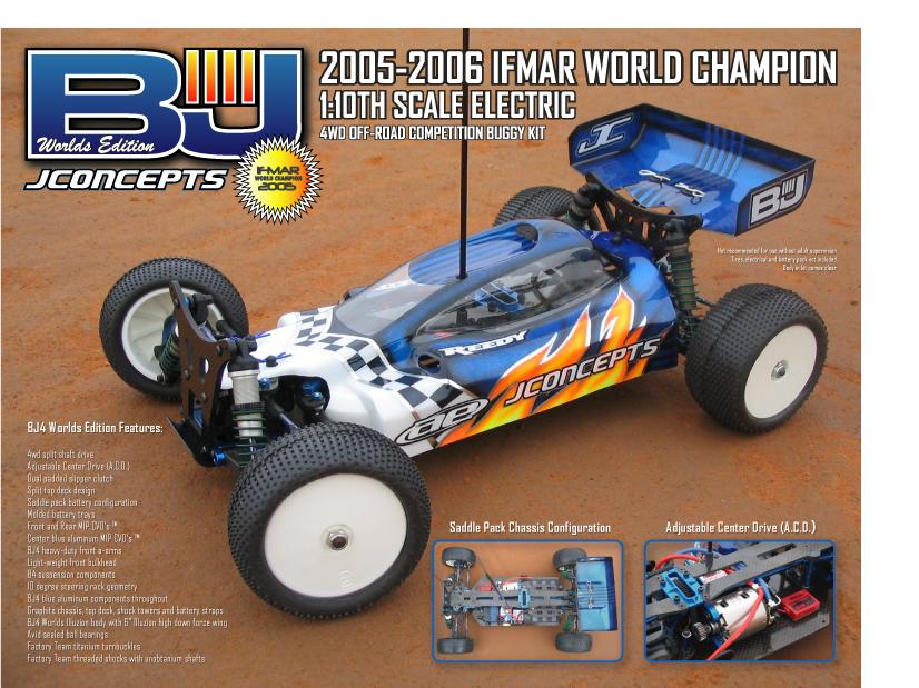
2 TOOLS TOOLS NEEDED TO BUILD THIS KIT 1. ALLEN WRENCHES A..050" B. 1/16" C. 5/64" D. 3/32" E. 2.5mm 2. NUT DRIVERS A. 3/16" B. 1/4" C. 11/32" 3. MISC. TOOLS A. NEEDLE NOSE PLIERS B. THREAD LOCKING COMPOUND (BLUE) C. HOBBY KNIFE (DANGER!) THIS KNIFE CUTS PLASTIC AND FINGERS WITH EQUAL EASE D. PRECISION RULER E. FLAT FILE 4. HELPFUL TOOLS (NOT REQUIRED) A. VERNIER CALIPERS B. HOBBY SCISSORS C. 2.5mm BALL END HEX DRIVER ITEMS NEEDED TO COMPLETE YOUR CAR: 1. R/C TWO CHANNEL SURFACE FREQUENCY RADIO SYSTEM 2. BATTERY PACK (6 CELL SADDLE PACK) 3. BATTERY CHARGER (PEAK DETECTION) 4. ELECTRONIC SPEED CONTROL 5. R/C ELECTRIC MOTOR 6. PINON GEAR (SIZE TO BE DETERMINED BY MOTOR CHOICE) 7. 1/10TH SCALE 4WD FRONT TIRES (BOX ART SHOWN: BLOCKHEAD) 8. 1/10TH SCALE BUGGY REAR TIRES (BOX ART SHOWN: X2000) BAG A CHASSIS COMPONENTS FRONT SHOCK TOWER STEERING RACK BATTERY TRAY CHASSIS TOP DECK (2 PIECES) REAR SHOCK TOWER BEARING BLOCK BATTERY STRAP STEP 1 CHASSIS PREPARATION: 1. FILE REAR TRANSMISSION SLOT WITH THE BOTTOM SURFACE OF THE FILE. FILE AT THE GREATEST ANGLE POSSIBLE WITHOUT THE TOP SURFACE OF THE FILE HITTING THE OTHER SIDE OF THE SLOT. SEE FIGURE REFER TO FIGURE 2 FOR COMPLETED COMPARISON. FILE FIGURE 1 FIGURE 2 NOTE CHASSIS ORIENTATION NOTE: THIS IS A CLEARANCE FOR THE BOTTOM OF THE REAR TRANSMISSION CASE. A PROPERLY FILED CHASSIS WILL ALLOW THE REAR TRANSMISSION CASE TO SIT FLAT ON THE CHASSIS. FILE CAREFULLY! USE THE PROPER CASE TO CHECK THE FIT WHILE REMOVING A SMALL AMOUNT OF MATERIAL AT A TIME. PAGE 1
3 BAG B CHASSIS COMPONENTS 540 x 5/16" 440 x 5/16" x 9 x x 5/16" SOCKET HEAD x MINI LOCKNUT #4 WASHER, ALUMINUM FRONT BULKHEAD CENTER MOTOR MOUNT CENTER BULKHEAD CENTER BULKHEAD CAP BATTERY POST REAR SUSPENSION MOUNT (FRONT) NOTE MOUNTING DIRECTION IN ASSEMBLY BELOW REAR SUSPENSION MOUNT (BACK) NOTE MOUNTING DIRECTION IN ASSEMBLY BELOW STEP 1 ASSEMBLING CHASSIS COMPONENTS: 1. ATTACH FRONT BULKHEAD TO CHASSIS WITH TWO 540 x 5/16" SCREWS. 2. ATTACH BEARING BLOCK WITH TWO SCREWS. SECURE WITH TWO 440 LOCKNUTS. 3. ATTACH CENTER MOTOR MOUNT TO CHASSIS WITH THREE 440 x 5/16" SCREWS. 4. ATTACH CENTER BULKHEAD TO CHASSIS WITH TWO 440 x 5/16" SCREWS. 5. ATTACH REAR SUSPENSION MOUNT (FRONT) WITH TWO 440 x 5/16" SCREWS. NOTE DIRECTION 6. ATTACH REAR SUSPENSION MOUNT (BACK) WITH TWO 440 x 5/16" SCREWS. NOTE DIRECTION FLAT EDGE OF FRONT MOUNT SHOULD FACE FORWARD APPLY BLUE THREAD LOCKING COMPOUND WHERE NOTED. (JUST A SMALL AMOUNT) 440 MINI LOCKNUTS BEARING BLOCK AND CHASSIS FROM BAG "A" FRONT BULKHEAD 540 x 5/16" (APPLY A SMALL AMOUNT OF THREAD LOCKING COMPOUND) BEARING BLOCK CENTER MOTOR MOUNT 440 x 5/16" x 3 (APPLY A SMALL AMOUNT OF THREAD LOCKING COMPOUND) CENTER BULKHEAD 440 x 5/16" (APPLY A SMALL AMOUNT OF THREAD LOCKING COMPOUND) REAR SUSPENSION MOUNT 440 x 5/16" (APPLY A SMALL AMOUNT OF THREAD LOCKING COMPOUND) PAGE 2
4 BAG B CENTER SLIPPER PARTS SLIPPER OUTDRIVE FEMALE SLIPPER OUTDRIVE MALE DIFF BOLT DIFF THRUST WASHER SLIPPER SPRING DIFF TNUT 78 TOOTH SPUR GEAR SLIPPER PAD SLIPPER PLATE 3/8 X 5/8 BEARING OUTDRIVE SHIM STEP 1 SLIPPER ASSEMBLY: SLIPPER PLATE 1. HOLD THE DIFF BOLT WITH A 5/64" ALLEN WRENCH. 2. SLIDE ONE THRUST WASHER ONTO THE DIFF BOLT. 3. SLIDE THE DIFF BOLT WITH THRUST WASHER INTO THE FEMALE SLIPPER OUTDRIVE. 4. WHILE ALIGNING THE HEXES ON EACH PART, SLIDE THE SLIPPER PLATE ONTO THE FEMALE SLIPPER OUTDRIVE. 5. HOLD THE PARTIAL ASSEMBLY WITH THE 5/64" ALLEN WRENCH SO THAT THE SLIPPER PLATE IS FACING UP. DIFF BOLT FEMALE SLIPPER OUTDRIVE THRUST WASHER ALIGN HEXES STEP 2 SLIPPER ADJUSTMENT: 1. STACK THE FOLLOWING PARTS ONTO THE PARTIAL ASSEMBLY IN THIS ORDER: A. SLIPPER PAD B. 78 TOOTH SPUR GEAR (ALIGN WITH SLIPPER PAD) C. SLIPPER PAD (ALIGN WITH SPUR GEAR) D. SLIPPER PLATE E. MALE SLIPPER OUTDRIVE (ALIGN WITH SLIPPER PLATE) MALE SLIPPER OUTDRIVE ALIGN HEXES APPLY A SMALL AMOUNT OF THREAD LOCKING COMPOUND TO THE THREADED, ALUMIUM PORTION SLIPPER SPRING TNUT 2. CAREFULLY ALIGN ALL THE HEX SHAPED PARTS WHILE THE SLIPPER PADS REST IN THE SPUR GEAR. 3. INSERT THE SLIPPER SPRING INTO THE MALE SLIPPER OUTDRIVE. 4. INSERT THE TNUT INTO THE MALE SLIPPER OUTDRIVE UNTIL IT TOUCHES THE DIFF SPRING. (APPLY A SMALL AMOUNT OF THREAD LOCKING COMPOUND WHERE SHOWN) 5. TIGHTEN THE SLIPPER USING THE 5/64" ALLEN WRENCH, BUT NOT COMPLETELY. JUST TIGHT ENOUGH TO HOLD THE COMPONENTS IN PLACE. SLIPPER PAD PARTIAL ASSEMBLY SPUR GEAR ALIGN HEX WITH FEMALE OUTDRIVE HEX SLIPPER PLATE SLIPPER PAD PAGE 3
5 STEP 3 SLIPPER ADJUSTMENT: COMPARE ASSEMBLY: 1. THE SLIPPER IS ONE OF THE MOST CRITICAL ADJUSTMENTS ON THE BJ4. REMEMBER, THE SLIPPER IS DESIGNED TO ABSORB IMPACTS FROM THE DRIVETRAIN. SETTING THE SLIPPER TOO TIGHT WILL ONLY CAUSE PREMATURE DAMAGE TO THE DRIVETRAIN. IN ADDITION, HAVING THE SLIPPER TOO LOOSE WILL NOT HELP CREATE TRACTION. 2. SCREW IN THE DIFF BOLT UNTIL THE SPRING IS FULLY COMNPRESSED. PAY CLOSE ATTENTION TO THE ALIGNMENT OF THE PARTS. DO NOT OVERTIGHTEN THE BOLT. WHEN YOU FEEL THE SPRING COMPRESSED, LOOSEN THE DIFF BOLT ONE TURN. 3. AFTER YOU HAVE DRIVEN THE CAR FOR ONE BATTERY PACK, CHECK THE SLIPPER ADJUSTMENT. IF NECESSARY, REPEAT STEP 2 ABOVE. 4. IF MORE SLIP IS DESIRED, LOOSEN THE DIFF BOLT 11/4 TURNS FROM BOTTOM. IF LESS SLIP IS DESIRED, LOOSEN THE DIFF BOLT 3/4 TURNS FROM BOTTOM. STEP 4 ASSEMBLING CHASSIS COMPONENTS: 1. SLIDE ONE OUTDRIVE SHIM AND ONE 3/8" x 5/8" BEARING ONTO EACH SIDE OF THE SLIPPER ASSEMBLY. 2. SLIDE THE COMPLETE SLIPPER ASSEMBLY DOWN INTO THE CHANNELS OF THE CENTER BULKHEADS. 3. ATTACH THE CENTER BULKHEAD CAP WITH FOUR SOCKET HEAD SCREWS. 4. ALIGN EACH BATTERY TRAY WITH THE SLOTS IN THE CHASSIS, AND SNAP INTO PLACE. 5. ATTACH EACH BATTERY POST WITH A SCREW. MAKE SURE TO ALIGN THE HEX ON EACH BATTERY POST WITH THE CORRESPONDING HEX IN THE BATTERY TRAY. 6. SLIDE THE BATTERY STRAPS ONTO THE BATTERY POSTS AS SHOWN BELOW. 7. ATTACH EACH BATTERY STRAP WITH TWO 440 x 5/16" SOCKET HEAD SCREWS AND TWO #4 WASHERS. CENTER BULKHEAD CAP OUTDRIVE SHIM 3/8" x 5/8" BEARING 440 x 5/16" SOCKET HEAD #4 WASHER BATTERY POST BATTERY TRAY FROM BAG "A" (APPLY A SMALL AMOUNT OF THREAD LOCKING COMPOUND) PAGE 4
6 BAG C DRIVETRAIN COMPONETS (DIFF ) DIFF THRUST WASHER 3/16 X 5/16 DIFF BEARING DIFF BOLT 3/32 DIFF BALL 2 5/64 THRUST BALL x 6 OUTDRIVE SHIM DIFF TNUT SHORT OUTDRIVE HUB LONG OUTDRIVE HUB DIFFERENTIAL RING GEAR DRIVE RING DIFF SPRING STEP 1 THRUST BALL ASSEMBLY: HOLD WITH 5/64" ALLEN WRENCH APPLY GENEROUS AMOUNT OF BLACK GREASE DIFF BOLT THRUST WASHERS 5/64 THRUST BALLS x 6 1. HOLD THE DIFF BOLT WITH THE 5/64" ALLEN WRENCH AND SLIDE ONE THRUST WASHER ONTO THE DIFF BOLT. 2. APPLY A GENEROUS AMOUNT OF BLACK GREASE TO THE WASHER ON THE SIDE FACING AWAY FROM THE BOLT HEAD. 3. PLACE SIX THRUST BALLS INTO THE GREASE AGAINST THE BOLT AND WASHER. ADD THE OTHER THRUST WASHER. THE GREASE WILL HOLD THE BALLS IN PLACE DURING ASSEMBLY, SANDWICHED BETWEEN THE WASHERS. STEP 2 SHORT HUB ASSEMBLY: 1. INSERT THE THRUST ASSEMBLY INTO THE SHORT OUTDRIVE HUB. 2. ADD A LIGHT COAT OF STEALTH LUBE TO THE SHORT HUB FACE WHERE SHOWN. 3. PLACE A DIFF DRIVE RING ONTO THE FACE OF THE SHORT HUB. 4. SLIDE A DIFF BEARING ONTO THE PROTRUSION OF THE SHORT HUB. THRUST ASSEMBLY 3/16 x 5/16 DIFF BEARING DIFF DRIVE RING SHORT OUTDRIVE HUB NOTE: REMOVE ANY OIL RESIDUE FROM OUTDRIVE HUB THOROUGHLY BEFORE APPLYING STEALTH LUBE SMEAR A SMALL AMOUNT OF STEALTH LUBE HERE TO HOLD THE DIFF DRIVE RING IN PLACE PAGE 5
7 STEP 3 DIFFERENTIAL RING GEAR: SHORT HUB ASSEMBLY 1. TRIM ANY BURRS FROM THE INSIDE OF THE GEAR WITH A HOBBY KNIFE. 2. ADD A GENEROUS AMOUNT OF STEATLH DIFF LUBE TO THE RING GEAR BALL HOLES AND PUSH IN THE TWELVE 3/32 DIFF BALLS. THEN PUSH IN THE LUBE THAT CAME OUT. TRIM ANY BURRS FROM THE INSIDE OF THE GEAR WITH A HOBBY KNIFE AFTER APPLYING THE STEALTH DIFF LUBE, SNAP THE 3/32 DIFF BALLS IN PLACE STEALTH DIFF LUBE STEP 4 LONG HUB ASSEMBLY: LONG OUTDRIVE HUB 3/16 x 5/16 DIFF BEARING DIFF DRIVE RING TNUT 1. INSERT THE DIFF SPRING INTO THE LONG OUTDRIVE HUB. 2. INSERT THE TNUT INTO THE LONG HUB UNTIL IT TOUCHES THE DIFF SPRING. 3. ADD A LIGHT COAT OF STEALTH LUBE TO THE LONG HUB FACE. 4. PLACE A DIFF DRIVE RING ONTO THE FACE OF THE LONG HUB. 5. INSERT THE 3/16 x 5/16 DIFF BEARING INTO THE LONG HUB. DIFF SPRING NOTE: REMOVE ANY OIL RESIDUE FROM OUTDRIVE HUB THOROUGHLY BEFORE APPLYING STEALTH LUBE. STEP 5 DIFF ASSEMBLY: 1. INSERT THE LONG HUB ASSEMBLY INTO THE SHORT HUB ASSEMBLY, MAKING SURE YOU LINE UP THE BOLT IN THE HUB AND THE BOLT THREADS INTO THE TNUT. CHECK ALIGNMENT OF THE HUBS 2. TIGHTEN THE DIFF WITH YOUR 5/64" ALLEN WRENCH, BUT NOT COMPLETELY. 3. SCREW IN THE DIFF BOLT A FEW TURNS THEN STOP TO ROTATE THE DIFF HUBS IN OPPOSITE DIRECTIONS. THEN SCREW IN THE BOLT SOME MORE. FOLLOW THIS PROCEDURE TO CHECK PROPER ALIGNMENT OF THE PARTS. THE FOLLOWING NOTE CLARIFIES THIS. READ THE FOLLOWING CAREFULLY AS YOU TIGHTEN THE DIFF BOLT, PAY CLOSE ATTENTION TO THE FEELING WHEN THE SPRING IS FULLY COMPRESSED. DO NOT OVERTIGHTEN THE BOLT. WHEN YOU FEEL THE SPRING COMPRESSED, LOOSEN THE DIFF BOLT 1/4 TURN. NO MORE, NO LESS. AFTER YOU HAVE DRIVEN THE CAR FOR ONE BATTERY PACK, RECHECK THE DIFF ADJUSTMENT AS ABOVE SO THAT WHEN YOU FEEL THE SPRING FULLY COMPRESSED, LOOSEN THE DIFF BOLT 1/4 TURN. NEVER ADJUST THE DIFF ANY OTHER WAY. NOW ASSEMBLE THE SECOND DIFF THE SAME WAY TIGHTEN USING 5/64" ALLEN WRENCH PAGE 6
8 STEP 6 FINAL DIFF ASSEMBLY: 1. SLIDE ONE OUTDRIVE SHIM AND ONE 3/8 x 5/8 BEARING ONTO EACH SIDE OF THE DIFF ASSEMBLY. 3/8 x 5/8 BEARING SCALE: 1:1 OUTDRIVE SHIMS, VERY IMPORTANT 3/8 x 5/8 BEARING CENTER CVD BAG CENTER CVD COMPONENTS CVD COUPLING CVD CROSS PIN CVD SET SCREW CENTER CVD BONE "REAR" CENTER CVD INPUT SHAFT CENTER CVD BONE "FRONT" STEP 7 CENTER CVD ASSEMBLY: 1. SPREAD A SMALL AMOUNT OF BLACK GREASE ON THE OUTSIDE OF THE CVD COUPLING AND INSERT THE COUPLING INTO THE AXLE AS SHOWN. 2. SPREAD A SMALL AMOUNT OF BLACK GREASE ON THE ROUND PORTION OF THE AXLE AND INSERT INTO THE CVD BONE, ALIGNING THE CROSS HOLES. 3. INSERT THE CROSS PIN, MAKING SURE IT IS EVENLY SPACED ON BOTH SIDES OF THE CVD BONE. 4. APPLY A SMALL AMOUNT OF MIP THREAD LOCKING COMPOUND TO THE SET SCREW. ANGLE AND TURN THE CVD SO THE SET SCREW CAN BE SCREWED IN WITH AN ALLEN WRENCH. 5. REPEAT THIS PROCEDURE FOR BOTH FRONT AND REAR CENTER CVD'S. CVD CROSS PIN SOLID APPLY A SMALL AMOUNT OF BLACK GREASE APPLY A SMALL AMOUNT OF THREAD LOCKING COMPOUND PAGE 7
9 BAG C INPUT SHAFT COMPONENTS * (ECLIPS ARE LOCATED IN THE SHOCK BAG) DRIVE PINON 3/16 x 3/8 BEARING DOWEL PIN INPUT SHAFT SHIM x 8 SMALL ECLIP* STEP 8 INPUT SHAFT ASSEMBLY: 1. SLIDE TWO INPUT SHAFT SHIMS AND TWO 3/16 X 3/8 BEARINGS ONTO THE INPUT SHAFT. 2. SLIDE TWO INPUT SHAFT SHIMS ONTO THE INPUT SHAFT. 3. INSTALL AND CENTER THE DOWEL PIN INTO THE INPUT SHAFT. 4. TRIM BURRS FROM THE DRIVE PINION EDGE WHERE SHOWN. SLIDE THE DRIVE PINION ON TO THE INPUT SHAFT. MAKE SURE THE DOWEL PIN ALIGNS PERFECTLY WITH THE SLOT IN THE PINION. ATTENTION! CAREFULLY TRIM ANY BURRS FROM THIS EDGE OF THE DRIVE PINION WITH A HOBBY KNIFE. 5. ADD THE SMALL ECLIP. 6. REPEAT THIS PROCEDURE FOR THE OTHER INPUT SHAFT. INPUT SHAFT SHIM INPUT SHAFT CENTER CVD BONE "FRONT" (SHOWN) DOWEL PIN DRIVE PINON 3/16" x 3/8" BEARING ECLIP STEP 9 COMPARE ASSEMBLY: 1. COMPARE YOUR ASSEMBLY CAREFULLY! 2. COMPLETE OTHER INPUT SHAFT ASSEMBLY TO MATCH. CENTER CVD BONE "FRONT" (SHOWN) PAGE 8
10 BAG C TRANSMISSION COMPONENTS 8 FRONT TRANSMISSION HOUSING REAR TRANSMISSION HOUSING SOCKET HEAD x 8 x x 5/16" 440 /8" SET SCREW STEP 10 TRANSMISSION CASE ASSEMBLY: 1. ATTACH THE FRONT, LOWER TRANSMISSION HOUSING TO THE CHASSIS AND FRONT BULKHEAD USING TWO 440 x 5/16" SCREWS IN THE FRONT AND TWO SCREWS IN THE BACK. 2. ATTACH THE REAR, LOWER TRANSMISSION HOUSING TO THE REAR OF THE CHASSIS USING FOUR SCREWS. 3. TEMPORARILY SCREW A 440 /8" SET SCREWS INTO EACH SIDE OF THE REAR SUSPENSION MOUNT (FRONT). LATER IN THE ASSEMBLY, IT WILL BE NECESSARY TO TIGHTEN THESE SET SCREWS AGAINST THE REAR HINGE PINS. A SMALL AMOUNT OF THREAD LOCKING COMPOUND WILL BE ADDED AT THAT TIME. 440 /8" SET SCREW 440 x 5/16" PAGE 9
11 STEP 11 TRANSMISSION ASSEMBLY: 1. INSTALL THE FRONT AND REAR DIFF ASSEMBLIES IN THE LOWER TRANSMISSION CASES AS SHOWN BELOW. 2. INSTALL THE FRONT AND REAR INPUT SHAFT ASSEMBLIES AS SHOWN BELOW. BE SURE TO INSERT THE DOGBONE END OF EACH CVD ASSEMBLY INTO THE CENTER SLIPPER OUTDRIVE. SOCKET HEAD 3. ADD A SMALL AMOUNT OF STEALTH LUBE TO THE FRONT SIDE OF THE RING GEAR AND PINON GEAR ON BOTH ASSEMBLIES. 4. ATTACH EACH UPPER TRANSMISSION CASE WITH FOUR SOCKET HEAD SCREWS AND TWO SCREWS. SOCKET HEAD CENTER CVD INPUT SHAFT "FRONT" CENTER CVD INPUT SHAFT "REAR" APPLY A SMALL AMOUNT OF STEALTH LUBE APPLY A SMALL AMOUNT OF STEALTH LUBE STEP 12 COMPARE DRIVETRAIN ASSEMBLY: PAGE 10
12 BAG D STEERING AND TOP DECK COMPONENTS SHORT STEERING BELLCRANK LONG STEERING BELLCRANK STEERING BUSHING.030" NYLON WASHER 1/8 /4 BEARING STEERING POST SHORT BALL END 440 /4" 440 x 5/16" x /2" 440 /4" 440 x 5/16" LONG BALL END x x 5/16" 440 MINI LOCKNUT x 8.030" ALUMINUM WASHER 1 TRANSMISSION SPACER FRONT BODY MOUNT FRONT TOWER MOUNT ANTENNA MOUNT BODY MOUNT PAD REAR TOWER MOUNT STEP 1 STEERING ASSEMBLY: 1. THREAD BOTH STEERING POSTS INTO THE STEERING BELLCRANKS AS SHOWN. PAY ATTENTION TO THE ANGLE ON THE LONG BELLCRANK. THE LONG SIDE OF THE BELLCRANK SHOULD ANGLE AWAY FROM THE CENTER OF THE ASSEMBLY. (APPLY A SMALL AMOUNT OF THREAD LOCKING COMPOUND) NYLON APPLY A SMALL AMOUNT OF THREAD LOCKING COMPOUND 2. SLIDE ONE.030" NYLON WASHER ONTO THE TOP OF EACH STEERING POST. 3. SLIDE ONE.030" ALUMINUM WASHER ON TO A SHORT BALL END AND FASTEN IT TO THE LONG BELLCRANK AS SHOWN. (APPLY A SMALL AMOUNT OF THREAD LOCKING COMPOUND) 4. SLIDE THREE.030" ALUMINUM WASHERS ONTO A LONG BALL END. INSERT THE BALL END WITH THE THREE WASHERS INTO THE BACK HOLE OF THE GRAPHITE STEERING RACK (THE FLAT EDGE OF THE STEERING RACK IS THE BACK EDGE). SECURE THE BALL END WITH ONE 440 MINI LOCKNUT. REPEAT FOR OTHER SIDE. NOTE DIRECTION 5. INSERT A STEERING BUSHING INTO THE GRAPHITE STEERING RACK (NOTE DIRECTION). SLIDE ONE 440 x 5/16" SCREW UP THROUGH THE BOTTOM OF THE RACK AND TIGHTEN THE SCREW INTO THE BELLCRANK. REPEAT FOR OTHER SIDE. (APPLY A SMALL AMOUNT OF THREAD LOCKING COMPOUND) APPLY A SMALL AMOUNT OF THREAD LOCKING COMPOUND PAGE 11
13 STEP 2 TOP DECK ASSEMBLY: 1. ATTACH THE FRONT TOWER MOUNT USING TWO 440 /4" SCREWS. (APPLY A SMALL AMOUNT OF THREAD LOCKING COMPOUND) 2. CAREFULLY FILE THE LEADING EDGE OF THE TOP PLATE SO IT IS AT THE SAME ANGLE AS THE FRONT TOWER MOUNT WHEN VIEWED FROM THE SIDE. (REFER TO ILLUSTRATION BELOW) 3. SLIDE ONE.030" WASHER ON EACH OF FOUR LONG BALL ENDS. INSERT THE BALL ENDS, WITH WASHERS, INTO THE HOLES SHOWN BELOW. SECURE THE BALL ENDS USING FOUR 440 MINI LOCKNUTS. 4. ATTACH THE FRONT BODY MOUNTS WITH TWO 440 /4" SCREWS. 5. ATTACH A BEARING BLOCK TO THE BOTTOM OF THE TOP DECK USING TWO SCREWS. SECURE WITH TWO 440 MINI LOCKNUTS. 6. ATTACH THE ANTENNA MOUNT TO THE TOP DECK USING TWO 256 /4" SCREWS. 7. ATTACH THE REAR TOWER MOUNT WITH TWO 440 /4" SCREWS FROM THE BOTTOM OF THE TOP DECK. FINISH ATTACHING THE REAR TOWER MOUNT BY ADDING TWO 440 /4" SCREWS. REFER TO ILLUSTRATION BELOW FOR LOCATION OF SCREWS. (APPLY A SMALL AMOUNT OF THREAD LOCKING COMPOUND) 440 /4" (APPLY A SMALL AMOUNT OF THREAD LOCKING COMPOUND) 256 x 5/16" FILE EDGE AS SHOWN BELOW 440 /4" (APPLY A SMALL AMOUNT OF THREAD LOCKING COMPOUND) 440 /4" (APPLY A SMALL AMOUNT OF THREAD LOCKING COMPOUND) LONG BALL END WITH ONE.030" ALUMINUM WASHER ANTENNA MOUNT 440 /4" FILING TOP DECK EDGE EDGE TOP DECK DETAIL A (LEFT SIDE VIEW) PAGE 12
14 STEP 3 TOP DECK ASSEMBLY: 1. INSERT TWO 1/8 X 1/4 BEARINGS INTO THE BEARING BLOCK ON THE CHASSIS. 2. SLIDE THE STEERING ASSEBLY INTO THE BEARINGS. 3. SLIDE ONE 1/8 X 1/4 BEARING ONTO THE TOP OF EACH STEERING POST. 4. TO ATTACH THE FRONT PORTION OF THE TOP DECK, LINE UP THE BEARING BLOCK ON THE BOTTOM OF THE TOP DECK WITH THE TWO BEARINGS ON TOP OF THE STEERING POSTS. PRESS THE TOP DECK DOWN INTO PLACE. 5. SLIDE ONE ALUMINUM TRANSMISSION SPACER BETWEEN THE UPPER TRANSMISSION CASE AND THE TOP DECK. INSERT ONE 440 /2" SCREW AND TIGHTEN. REFER TO ILLUSTRATION BELOW FOR LOCATION. 6. FINISH SECURING THE FRONT PORTION OF THE TOP DECK WITH THREE SCREWS AND TWO 440 x 5/16" SCREWS. REFER TO ILLUSTRATION BELOW FOR LOCATION OF SCREWS. (APPLY A SMALL AMOUNT OF THREAD LOCKING COMPOUND TO THE 440 x 5/16" SCREWS) 7. POSITION THE REAR PORTION OF THE TOP DECK AS SHOWN BELOW, AND REPEAT STEP 5 ABOVE. 8. FINISH SECURING THE REAR PORTION OF THE TOP DECK WITH TWO SCREWS AND TWO 440 x 5/16" SCREWS. REFER TO ILLUSTRATION BELOW FOR LOCATION OF SCREWS. (APPLY A SMALL AMOUNT OF THREAD LOCKING COMPOUND TO THE 440 x 5/16" SCREWS) 9. ATTACH ONE BODY MOUNT PAD ON EACH SIDE OF THE CHASSIS USING A SCREW. 440 x 5/16" (APPLY A SMALL AMOUNT OF THREAD LOCKING COMPOUND) 440 /2" x /2" TRANSMISSION SPACER TRANSMISSION SPACER PAGE 13
15 CVD BAG FRONT CVD COMPONENTS CVD COUPLING CVD CROSS PIN CVD SET SCREW CVD ROLL PIN BEARING SPACER CVD FRONT HEX CVD FRONT WHEEL NUT CVD FRONT AXLE CVD FRONT BONE CVD BAG REAR CVD COMPONENTS CVD COUPLING CVD CROSS PIN CVD SET SCREW CVD ROLL PIN CVD AXLE SHIM (THIN) x 6 CVD AXLE SHIM (THICK) CVD REAR WHEEL NUT CVD REAR AXLE CVD REAR BONE STEP 1 FRONT/REAR CVD ASSEMBLY: 1. SPREAD A SMALL AMOUNT OF BLACK GREASE ON THE OUTSIDE OF THE CVD COUPLING AND INSERT THE COUPLING INTO THE AXLE AS SHOWN. 2. SPREAD A SMALL AMOUNT OF BLACK GREASE ON THE ROUND PORTION OF THE AXLE AND INSERT INTO THE CVD BONE, ALIGNING THE CROSS HOLES. 3. INSERT THE CROSS PIN, MAKING SURE IT IS EVENLY SPACED ON BOTH SIDES OF THE CVD BONE. 4. APPLY A SMALL AMOUNT OF MIP THREAD LOCKING COMPOUND TO THE SET SCREW. ANGLE AND TURN THE CVD SO THE SET SCREW CAN BE SCREWED IN WITH AN ALLEN WRENCH. 5. REPEAT THIS PROCEDURE FOR ALL OF THE CVD'S. SET THE COMPLETED CVD'S AND ADDITIONAL HARDWARE ASIDE FOR LATER ASSEMBLIES. CVD CROSS PIN SOLID APPLY A SMALL AMOUNT OF THREAD LOCKING COMPOUND APPLY A SMALL AMOUNT OF BLACK GREASE APPLY A SMALL AMOUNT OF BLACK GREASE PAGE 14
16 BAG E FRONT END COMPONENTS KING PIN 440 /4" 440 x 5/16" SOCKET HEAD.030 ALUMINUM WASHER 440 MINI LOCKNUT 256 /8" PIVOT SLEEVE FRONT AARM CASTER BLOCK LEFT & RIGHT EACH STEERING BLOCK LEFT & RIGHT EACH FRONT HINGE PIN BRACE SHORT BALL END 3/16 x 3/8 BEARING TITANIUM TURNBUCKLE 1.775" (STEERING) HINGE PIN 1.55" (FRONT INNER) BALL CUP 2 BALL END DUST COVER 4 TITANIUM TURNBUCKLE 2.00" (CAMBER) HINGE PIN 1.OO" (FRONT OUTER) STEP 1 STEERING AND CASTER BLOCK ASSEMBLY: 1. INSTALL ONE 3/16 x 3/8 BEARING ONTO THE CVD AXLE. SLIDE THE AXLE ASSEMBLY INTO THE BACK OF THE STEERING BLOCK. 2. IN ORDER, SLIDE A BEARING SPACER, 3/16 x 3/8 BEARING, AND CVD FRONT HEX ONTO THE CVD AXLE. 3/16 x 3/8 BEARING KING PIN 3. PRESS THE BEARING INTO THE STEERING BLOCK AND INSERT A ROLL PIN THROUGH THE GROOVE IN THE CVD HEX AND INTO THE AXLE. 5. PARTIALLY THREAD A FRONT WHEEL NUT ON THE AXLE. 6. SLIDE THE CVD BONE THROUGH THE CASTER BLOCK. WHEN ANGLED CORRECTLY, THE CVD BONE WILL DROP THROUGH THE CASTER BLOCK FREELY. FIT THE STEERING BLOCK OVER THE CASTOR BLOCK AND SECURE IT USING TWO KING PIN SCREWS. 7. SLIDE ONE.030" WASHER ON EACH OF TWO SHORT BALL ENDS. THREAD ONE BALL END WITH WASHER INTO THE CASTER BLOCK. (APPLY A SMALL AMOUNT OF THREAD LOCKING COMPOUND) 8. SLIDE ONE SHORT BALL END WITH WASHER INTO THE STEERING BLOCK. SECURE IT WITH ONE 440 MINI LOCKNUT. 9. REPEAT FOR THE OPPOSITE SIDE ASSEMBLY. ATTENTION! NOTE DIRECTION OF STEERING BLOCK AND CASTER BLOCK 3/16 x 3/8 BEARING PAGE 15
17 STEP 2 FRONT SUSPENSION ASSEMBLY: 1. INSERT BOTH PIVOT SLEEVES INTO THE FRONT BULKHEAD. 2. ALIGN THE FRONT AARMS WITH THE PIVOT SLEEVES AND PRESS THE FRONT INNER HINGE PINS INTO PLACE. 3. SLIDE THE FRONT HINGE PIN BRACE OVER THE FRONT INNER HINGE PINS UNTIL IT PRESSES AGAINST THE FRONT BULKHEAD. NOTE THE DIRECTION AND LOCATION OF THE 256 HOLES IN THE ILLUSTRATION BELOW. 4. ATTACH THE FRONT SHOCK TOWER USING TWO SCREWS AT THE BOTTOM AND TWO 440 /4" SCREWS AT THE TOP. (APPLY A SMALL AMOUNT OF THREAD LOCKING COMPOUND) 5. CAPURE THE FRONT INNER HINGE PINS BY INSERTING TWO 256 /8" SCREWS INTO THE FRONT HINGE PIN BRACE. 6. CHECK TO MAKE SURE SUSPENSION ARMS PIVOT FREELY. 440 /4" 256 /8" FRONT INNER HINGE PIN STEP 3 FRONT SUSPENSION ASSEMBLY: 1. POSITION THE CASTER BLOCK ASSEMBLIES AS SHOWN AND SLIDE THE FRONT OUTER HINGE PINS INTO PLACE. 2. CAPTURE THE FRONT OUTER HINGES BY INSERTING A 256 /8" SCREW INTO EACH AARM. 3. PUT BALL END DUST COVERS ON THE FRONT SUSPENSION AND TOP DECK BALL ENDS. 4. MAKE SURE THE CASTER BLOCKS PIVOT FREELY IN THE AARMS. 256 /8" FRONT OUTER HINGE PIN PAGE 16
18 STEP 4 FRONT TURNBUCKLE ASSEMBLY: 1. TWIST THE BALL CUPS ON TO EACH BLUE TITANIUM TURNBUCKLE UNTIL YOU GET THE DIMENSION SHOWN FOR EACH PART. 2. LOCATE THE NOTCH ON EACH TURNBUCKLE AND ROTATE THEM SO THAT IT IS LOCATED ON THE OUTSIDE OF THE CAR ON THE LEFT AND THE INSIDE ON THE RIGHT. SNAP ALL OF THE FRONT TURNBUCKLES INTO PLACE WHERE SHOWN. MAKE SURE THAT ALL OF THE CVD BONES ARE IN THE SLOTS OF THE OUTDRIVE HUBS FRONT CAMBER TURNBUCKLE 2.00": SCALE 1: FRONT STEERING TURNBUCKLE 1.775": SCALE 1:1 CAMBER TURNBUCKLE STEERING TURNBUCKLE BAG F REAR END COMPONENTS LONG BLACK BALL END 256 /8" 440 MINI LOCKNUT.030 NYLON WASHER HINGE PIN 1.O6" (REAR OUTER) HINGE PIN 2.00" (REAR INNER) REAR AARM LEFT & RIGHT EACH HUB CARRIER LEFT & RIGHT EACH 3/16 x 3/8 BEARING BEARING SPACER TITANIUM TURNBUCKLE 2.00" (CAMBER) STEP 1 HUB CARRIER ASSEMBLY: 1. SLIDE TWO SMALL AXLE SHIMS AND ONE 3/16 x 3/8 BEARING ONTO THE CVD AXLE. SLIDE THE AXLE ASSEMBLY INTO THE BACK OF THE HUB CARRIER. THIN AXLE SHIMS 2. IN ORDER, SLIDE A BEARING SPACER, 3/16 x 3/8 BEARING, AND ONE THICK AXLE SHIM ONTO THE CVD AXLE. 3. PRESS THE BEARING INTO THE HUB CARRIER AND INSERT A ROLL PIN INTO THE AXLE. 4. PARTIALLY THREAD A REAR WHEEL NUT ON THE AXLE. ROLL PIN 5. THREAD ONE LONG BLACK BALL END INTO THE MIDDLE HOLE ON THE HUB CARRIER. SECURE IT USING ONE 440 MINI LOCKNUT. REFER TO ILLUSTRATION FOR LOCATION. LONG BLACK BALL END 6. REPEAT FOR THE OPPOSITE ASSEMBLY. ATTENTION! THIS IS A LEFT SIDE ASSEMBLY ILLUSTRATION, NOTE DIRECTION AND CONFIGURATION OF HUB CARRIER PAGE 17
19 STEP 2 REAR SUSPENSION ASSEMBLY: 1. ATTACH THE REAR SHOCK TOWER WITH FOUR 440 x 5/16" SOCKET HEAD SCREWS. (APPLY A SMALL AMOUNT OF THREAD LOCKING COMPOUND) 2. ALIGN THE REAR AARMS BETWEEN THE REAR SUSPENSION MOUNTS. SLIDE THE REAR INNER HINGE PINS INTO PLACE AND SECURE THEM WITH WITH THE 440 SET SCREWS. (APPLY A SMALL AMOUNT OF THREAD LOCKING COMPOUND) 3. POSITION THE HUB CARRIER ASSEMBLY AS SHOWN AND SLIDE THE REAR OUTER HINGE PINS PARTIALLY THROUGH THE HUB CARRIERS. POSITION TWO.030" NYLON WASHERS BEHIND EACH HUB CARRIER AND CONTINUE TO PUSH THE HINGE PIN THROUGH THE WASHERS INTO THE AARM. 4. CAPTURE THE OUTER HINGE PINS WITH A 256 /8" SCREW INTO EACH AARM. 440 x 5/16" SOCKET HEAD (APPLY A SMALL AMOUNT OF THREAD LOCKING COMPOUND) REAR INNER HINGE PIN 440 /8" SET SCREW (APPLY A SMALL AMOUNT OF THREAD LOCKING COMPOUND) 5. PUT BALL END DUST COVERS ON ALL OF THE REAR SUSPENSION BALL ENDS. 6. MAKE SURE THE AARMS AND HUB CARRIERS PIVOT FREELY. ATTENTION! THIS IS A LEFT SIDE ASSEMBLY ILLUSTRATION, NOTE DIRECTION AND CONFIGURATION OF HUB CARRIER 256 /8" REAR OUTER HINGE PIN STEP 3 REAR TURNBUCKLE ASSEMBLY: 1. TWIST THE BALL CUPS ONTO EACH BLUE TITANIUM TURNBUCKLE UNTIL YOU GET THE DIMENSION SHOWN FOR EACH EACH PART. 2. LOCATE THE NOTCH ON EACH TURNBUCKLE AND ROTATE THEM SO THAT IT IS LOCATED ON THE OUTSIDE OF THE CAR ON THE LEFT AND THE INSIDE ON THE RIGHT. SNAP ALL THE REAR TURNBUCKLES INTO PLACE WHERE SHOWN. MAKE SURE THAT ALL THE CVD BONES ARE IN THE SLOTS OF THE OUTDRIVE HUBS REAR CAMBER TURNBUCKLE 2.00": SCALE 1:1 STEP 4 COMPARE SUSPENSION ASSEMBLY: PAGE 18
20 SHOCK BAG SHOCK COMPONENTS 440 x 3/4" 440 /2" SOCKET HEAD 440 PLAIN NUT GOLD WASHER SHOCK BUSHING SHOCK NUT.030 TRAVEL LIMITER ECLIP ROLL SHOCK PISTON #1, #2, #3 (TREE) SMALL SHOCK SPACER x 8 (TREE) LARGE SHOCK SPACER (TREE) SHOCK SNAP RETAINER (TREE) SHOCK ORING x 8 SHOCK CAP ORING SHOCK CAP SHOCK EYELET SHOCK PIVOT BUSHING THREAED SHOCK COLLAR SHOCK COLLAR ORING SPRING RETAINER SPRING CUP REAR SPRING (BLACK) FRONT SPRING (SILVER) FRONT SHOCK BODY (.89") FRONT SHOCK SHAFT (.89") REAR SHOCK BODY (1.18") REAR SHOCK SHAFT (1.02") SETUP NOTES: PAGE 21
21 STEP 1 SHOCK ASSEMBLY: BUILD ALL FOUR SHOCKS USING THIS METHOD ATTENTION: BUILDING THE SHOCKS IS ONE OF THE MOST IMPORTANT PARTS OF THE KIT ASSEMBLY. PLEASE READ THROUGH THE FOLLOWING STEPS COMPLETELY BEFORE BEGINNING. 1. BEGIN THE SHOCK ASSEMBLY BY FIRST TRIMMING EACH PART OFF THE SHOCK PARTS TREE. CAREFULLY TRIM EACH PART FROM THE PARTS TREE SO NO PART OF THE TWO MOLDING RUNNERS REMAIN. IT IS SAFER TO REMOVE A TINY AMOUNT OF THE PART THAN TO RISK THE CHANCE OF A BURR REMAINING. SHORT BLADE SCISSORS OR A HOBBY KNIFE WILL WORK FINE. RUN YOUR FINGER OVER THE EDGES TO FEEL FOR BURRS YOU CANNOT SEE. REMOVE ANY BURRS YOU FIND. BURRS CAN KEEP THE PARTS FROM SNAPPING IN CORRECTLY, AND CAN CAUSE THE SHOCK TO LEAK OR THE SHAFT TO JAM. 2. IN ORDER, LOAD THE SHOCK TOOL WITH THE FOLLOWING PARTS: (REFER TO FIGURE A BELOW) A. SHOCK SNAP RETAINER B. SMALL SHOCK SPACER.030" C. SHOCK ORING D. LARGE SHOCK SPACER E. SHOCK ORING F. SMALL SHOCK SPACER.030" 3. ADD 34 DROPS OF THE INCLUDED SHOCK OIL TO THE SHOCK SEAL PARTS WHILE IT IS ON THE SHOCK TOOL. 4. INSERT THE TOOL TIP INTO THE SHOCK BODY ALL THE WAY. PUSH EASILY UNTIL THE PARTS SNAP INTO PLACE. 5. CHECK THE TOOL HEIGHT IN FIGURE B BELOW AND COMPARE IT TO YOUR ASSEMBLY. IF YOUR SHOCKS DO NOT SNAP TOGETHER EASILY, CHECK THE PARTS FOR BURRS AGAIN. 6. ADD 12 DROPS OF OIL TO THE THREADS ON TOP OF THE SHOCK BODY. SLIDE THE SHOCK BODY ORING OVER THE THREADS. (USE THE BLACK ORINGS INCLUDED WITH ALL OF THE INNER SHOCK PARTS) 7. INSERT THE SHOCK COLLAR ORING INTO THE THREADED SHOCK COLLAR. THREAD THE SHOCK COLLAR ON ALL THE WAY UP THE SHOCK BODY. (USE THE BLACK ORINGS PACKAGED WITH THE SHOCK COLLARS) 8. COMPARE YOUR ASSEMBLY TO FIGURE C BELOW. SHOCK TOOL SNAP RETAINER SMALL SHOCK SPACER SHOCK BODY ORING SHOCK ORING LARGE SHOCK SPACER SHOCK ORING SHOCK COLLAR ORING FIGURE A FIGURE B FIGURE C PAGE 22
22 STEP 2 SHOCK ASSEMBLY: BUILD ALL FOUR SHOCKS USING THIS METHOD ATTENTION: BUILDING THE SHOCKS IS ONE OF THE MOST IMPORTANT PARTS OF THE KIT ASSEMBLY. PLEASE READ THROUGH THE FOLLOWING STEPS COMPLETELY BEFORE BEGINNING. 1. INSTALL AN ECLIP ON BOTH SIDES OF THE SHOCK PISTON. USE #3 PISTONS FOR THE FRONT SHOCKS WITH NO LIMITERS. USE #1 PISTONS FOR THE REAR SHOCKS WITH ONE LIMITER. 2. THREAD THE SHOCK EYELET ONTO THE SHAFT. THEN, SNAP THE PIVOT BALL INTO THE EYELET. 3. FILL THE SHOCK HALF FULL WITH SHOCK OIL AND MOVE THE SHOCK SHAFT UP AND DOWN A FEW TIMES. MAKE SURE TO PUSH THE PISTON PAST THE HALF WAY POINT. 4. FIGURE D SHOWS A SHOCK WITH THE SHAFT AT ITS HALF WAY POINT. #3 PISTON (FRONT) #1 PISTON (REAR) ONE.030" TRAVEL LIMITER ON REAR SHOCKS ONLY! FIGURE A FIGURE B FIGURE C FIGURE D 5. FILL THE SHOCK BODY TO THE TOP OF THE THREADS WITH SHOCK OIL. 6. THREAD THE SHOCK CAP ON ALL THE WAY. THEN, LOOSEN IT A FEW TURNS. (SEE FIGURE G BELOW) 7. SLOWLY PUSH THE SHOCK SHAFT ALL THE WAY UP TO BLEED OUT EXCESS OIL. THEN, TIGHTEN THE CAP. NOW, WHEN YOU COMPRESS THE SHOCK, IT SHOULD ONLY REBOUND ABOUT.25". REPEAT THE BLEEDING PROCESS UNTIL.25" REBOUND IS ACHIEVED. 8. SLIDE THE SPRING AND RETAINER ONTO THE SHOCK. PUSH THE SPRING RETAINER UP ENOUGH TO INSERT THE SPRING CUP OVER THE SHOCK EYELET. 9. THREAD THE SHOCK COLLAR DOWN UNTIL IT TOUCHES THE SPRING. SET THE RIDE HEIGHT AFTER THE ELECTRICAL IS MOUNTED IN THE CAR. FIGURE E FIGURE F FIGURE G FIGURE H FIGURE I PAGE 23
23 STEP 3 SHOCK MOUNTING: 1. ATTACH THE BOTTOM OF THE FRONT SHOCKS TO THE OUTSIDE HOLES ON THE FRONT AARMS. USE THE 440 /2" SOCKET HEAD SCREWS WITH A GOLD WASHER ON EACH. 2. ATTACH THE BOTTOM OF THE REAR SHOCKS TO THE INSIDE HOLES ON THE REAR AARMS. USE THE 440 /2" SOCKET HEAD SCREWS WITH A GOLD WASHER ON EACH. 3. SLIDE THE 440 x 3/4" SCREWS THROUGH THE MIDDLE HOLES ON THE FRONT AND REAR SHOCK TOWERS. SECURE THE SCREWS WITH THE 440 PLAIN NUTS. SLIDE THE SHOCK PIVOTS AND TOP OF EACH SHOCK ONTO THE SCREWS. SECURE THE SHOCKS WITH THE PLASTIC SHOCK NUTS. DO NOT OVER TIGHTEN THE PLASTIC SHOCK NUTS. THE SHOCKS SHOULD PIVOT FREELY. 440 PLAIN NUT SHOCK NUT SHOCK PIVOT 440 PLAIN NUT SHOCK PIVOT 440 x 3/4" SHOCK NUT 440 x 3/4" GOLD WASHER GOLD WASHER 440 /2" SOCKET HEAD 440 /2" SOCKET HEAD STEP 4 COMPARE COMPLETED SUSPENSION ASSEMBLY: PAGE 24
24 BAG G MISCELLANEOUS COMPONENTS 3mm x 8mm SOCKET HEAD SOCKET HEAD x /4" GOLD WASHER x 6 SHORT BALL END BODY CLIP x 5 SHORT BALL CUP TITANIUM TURNBUCKLE SERVO MOUNT SERVO MOUNT SPACERS THICK THIN SERVO HORNS A, F, H, J EA REAR BODY MOUNT WING MOUNT WING MOUNT SPACER FRONT BUMPER STEP 1 SERVO HORN ASSEMBLY: 1. INSTALL A SHORT BALL END INTO THE SERVO HORN THAT MATCHES YOUR BRAND OF SERVO. 2. ALIGN THE SPLINES ON THE SERVO HORN AT A VERY SLIGHT ANGLE TOWARD THE BODY OF THE SERVO, AND PRESS THE SERVO HORN ONTO THE SERVO. 3. USE THE SCREW THAT WAS SUPPLIED WITH YOUR SERVO TO SECURE THE SERVO HORN. (SUPPLIED WITH YOUR SERVO) SERVO HORN SERVO SPLINE SCREW SHORT BALL END ATTENTION! AFTER ALL THE ELECTRONICS ARE INSTALLED, IT MAY BE NECESSARY TO COME BACK AND CENTER THE SERVO HORN ON THE SPLINE. STEP 2 STEERING TURNBUCKLE ASSEMBLY: TWIST THE BALL CUPS ONTO THE BLUE TITANIUM TURNBUCKLE UNTIL YOU GET THE DIMENSION SHOWN. STEERING TURNBUCKLE 1.00": SCALE 1:1 PAGE 25
25 STEP 3 MISCELLANEOUS ASSEMBLY: 1. ATTACH THE SERVO MOUNTS TO YOUR SERVO BY USING FOUR SCREWS WITH A GOLD WASHERS ON EACH. CHECK THE ALIGNMENT OF YOUR SERVO WITH THE SUPPLIED MOUNTS. SOME SERVOS REQUIRE SPACERS IN FRONT OF THE ACTUAL SERVO MOUNTS. TYPICALLY, AIRTRONICS SERVOS WILL REQUIRE THE THICK SERVO MOUNT SPACERS. JR AND FUTABA SERVOS WILL USE THE THIN SERVO MOUNT SPACERS. 2. SECURE THE SERVO MOUNTS TO THE CHASSIS WITH TWO SCREWS. 3. PUT THE BALL END DUST COVERS ON THE SERVO HORN AND THE STEERING BELLCRANK BALL ENDS. 4. ATTACH THE ASSEMBLED STEERING TURNBUCKLE TO THE BALL ENDS LOCATED ON THE SERVO HORN AND STEERING BELLCRANK. 5. INSTALL THE WING MOUNTS USING FOUR SCREWS. 6. INSTALL THE REAR BODY MOUNT USING ONE SOCKET HEAD SCREW. 7. INSTALL THE CHASSIS TAPE ON THE BOTTOM OF THE CHASSIS. USE THE PHOTOS LOCATED AT THE END OF THIS MANUAL FOR A REFERENCE. 8. INSTALL THE FRONT BUMPER OVER THE CHASSIS TAPE WITH TWO 440 /4" SCREWS. (APPLY A SMALL AMOUNT OF THREAD LOCKING COMPOUND) STEERING TURNBUCKLE THIN SPACER SERVO MOUNTS REAR BODY MOUNT WING MOUNT SOCKET HEAD 440 /4" (APPLY A SMALL AMOUNT OF THREAD LOCKING COMPOUND) PAGE 26
26 STEP 4 MISCELLANEOUS ASSEMBLY: 1. ATTACH THE REST OF YOUR ELECTRICAL TO THE CHASSIS USING THE INCLUDED SPEED CONTROL AND RECEIVER TAPE. KEEP IN MIND THAT THE GRAPHITE CHASSIS AND TOP DECK ARE VERY CONDUCTIVE. IT IS RECOMMENED THAT YOU PUT TWO LAYERS OF SPEED CONTROL AND RECEIVER TAPE UNDER YOUR ELECTRONICS. RUN YOUR RECEIVER ANTENNA WIRE UP THROUGH THE ANTENNA MOUNT AND TUBE. PRESS THE ANTENNA TUBE DOWN INTO THE MOUNT. INSTALL THE ANTENNA CAP TO HOLD THE ANTENNA WIRE IN PLACE. USE THE PHOTOS LOCATED AT THE END OF THIS MANUAL FOR A REFERENCE. 2. CUT OUT THE ILLUZION WING ALONG THE CUT LINES USING LEXAN SCISSORS. ATTACH THE WING TO THE MOUNTS USING THE WING MOUNT SPACERS FIRST, THEN THE INCLUDED BODY CLIPS. 3. MOUNT YOUR 4WD FRONT TIRES OF CHOICE ON THE FRONT WHEELS AND INSTALL THE TIRES AND WHEELS TO THE FRONT AXLES USING THE THIN 832 LOCKNUTS. 4. MOUNT YOUR BUGGY REAR TIRES OF CHOICE ON THE REAR WHEELS AND INSTALL THE TIRES AND WHEELS TO THE REAR AXLES USING THE STANDARD 832 LOCKNUTS. WING MOUNT SPACERS BJ4 ILLUZION 6" HIGH DOWNFORCE WING ANTENNA TUBE WITH CAP BODY CLIPS SPEED CONTROL AND RECEIVER CAN BE MOUNTED THE WAY SHOWN. IF MORE ROOM IS REQUIRED, EITHER UNIT CAN BE MOUNTED ON THE OTHER SIDE OF THE CAR. 832 LOCKNUT 832 THIN LOCKNUT PAGE 27

27 STEP 5 MOTOR INSTALLATION: 1. INSTALL YOUR PINON OF CHOICE ON THE MOTOR PRIOR TO INSTALLATION. THE PINON GEAR WILL BE DETERMINED BY YOUR MOTOR SELECTION. THE RECOMMENDED PINON FOR A 10 MODIFIED MOTOR IS A 20 TOOTH. 2. INSTALL YOUR MOTOR USING THE 3mm x 8mm SOCKET HEAD SCREWS WITH A GOLD WASHERS ON EACH. THREAD THE BOTTOM SCREW PARTIALLY INTO THE MOTOR PRIOR TO INSTALLATION. 3. SET THE GEAR MESH SO THAT THE PINON GEAR AND THE SPUR GEAR ROCK BACK AND FORTH A SMALL AMOUNT. 4. TIGHTEN THE SCREWS TO SECURE THE MOTOR. 3mm x 8mm SOCKET HEAD SCREWS WITH GOLD WASHERS NOTE: IT IS HELPFUL TO HAVE A 2.5mm BALL END HEX DRIVER FOR MOTOR INSTALLATION. STEP 6 BODY FINISHING AND COMPLETED ASSEMBLY: 1. THE BODY COMES CLEAR. MASK AND PAINT THE INSIDE OF YOUR BODY AS DESIRED. WINDOW MASKS ARE INCLUDED FOR YOUR CONVENIENCE. BE SURE TO USE A PAINT THAT IS SPECIFICALLY FORMULATED TO ADHERE TO LEXAN. 2. CUT OUT THE BJ4 WORLDS EDITION BODY ALONG THE CUT LINES ON THE BODY USING LEXAN SCISSORS. NEXT, DRILL OUT THE LOCATIONS FOR THE BODY MOUNTS AND ANTENNA. MOUNT THE BODY USING THE INCLUDED BODY CLIPS. FOR A MORE SECURE ATTACHMENT, APPLY SOME HOOK AND LOOP TAPE TO THE BODY MOUNT PADS AND BODY. TIRES, ELECTRICAL AND BATTERY PACK NOT INCLUDED. BODY IN KIT COMES CLEAR. SOME DECALS SOLD SEPARATELY. PAGE 28


28 CHASSIS TAPE INSTALLATION SHOWN WITHOUT FRONT BUMPER ELECTRICAL LAYOUT ELECTRICAL LAYOUT ELECTRICAL LAYOUT BATTERY PACK WITH JUMPER WIRE OVER TOP DECK PAGE 29

29 BJ4 WORLDS EDITION SPECIFICATIONS Wheel Base: (278mm) Vehicle Width: 9.65 (245mm) Weight (ready to run): 3 lbs. 7.6 oz. (1575g) Internal gear ratio: 2.50:1 Front bulkhead kickup: 8 degrees Front castor blocks: 10 degrees Standard rear hub carrier toein: 0 degrees Standard suspension mount toein: 3 degrees Standard suspension mount antisquat: 2 degrees FINAL ADJUSTMENTS Radio Adjustments: Use the following steps to make the final adjustments to your car: 1. Turn the transmitter on. 2. Make sure the motor is disconnected. 3. Connect your battery pack and turn the power switch on. 4. Move the steering control on the transmitter to the right and left. Do the wheels move in the correct direction? If not, you must reverse the steering servo direction on your transmitter (see radio manual). 5. Adjust your steering trim (see radio manual) until the steering bell cranks are centered under the top deck. Then, using the two steering turnbuckles, finetune the adjustment on the front wheels so they are pointing straight ahead. Check them once again when the car is race ready and the ride height has been set. 6. Adjust the ESC (electronic speed control) according to the speed control manufacturer s instructions. Some manufacturers have the motor connected during adjustment and some do not. Now, turn the power switch off. 7. Connect the motor. Place your car on a block or car stand so that all four wheels are elevated. Turn the power switch on again. Check the ESC and steering settings you have made and then turn the power switch back off. 8. Remember this! The transmitter is always the FIRST TO BE TURNED ON and THE LAST TO BE TURNED OFF. Advanced Radio Adjustments: Some radio systems offer dual rate and end point adjustments (see radio manual). If your radio has these adjustments, adjust the dual rate to 100%. Using the end point adjustments, adjust the left and right steering throw so the servo stops at the same point as the car s physical steering stops. If less steering is desired, reduce the dual rate adjustment in small increments. Advanced Speed Control Adjustments: Some speed controls offer drag brake (see speed control manual). The drag brake adjustment can be use to automatically apply braking power when the driver lets off the throttle completely. This adjustment can be used when the racing surface has enough traction that the driver feels comfortable allowing the speed control to automatically slow the car down when entering the turns. This is a tricky adjustment that can work well when the traction is high enough. However, it tends to unsettle the car and can lead to unpredictable responses. PAGE 30

30 Another adjustment some speed controls offer is an initial brake setting (see speed control manual). This setting determines the minimum braking power the speed control applies when the driver initially applies the brake. This is a helpful adjustment for most track conditions. Reducing the initial brake makes the car more predictable, but less responsive. Battery Pack Assembly: Here is the preferred way to assemble battery packs for the BJ4 Worlds Edition. Solder the individual cell connections as shown. Team racers prefer battery bars for sturdier connections. Use a six inch long piece of 12gauge wire for the jumper between each threecell pack. Motor Gearing: To get the most from your motor, proper gearing is important. You can calculate the final drive ratio by using the following formula: 2.5 x (spur gear / pinion gear) = final drive ratio Recommended competition modified motors are 13 2, 12 2, 11 2 or Popular brushless motor combinations have also been added to the suggested gearing chart below. Pinion Spur Final Ratio 24 degree stock motor Motor Type and Wind :1 19 turn motor :1 13 turn motor :1 12 turn motor :1 11 turn motor :1 10 turn motor :1 Reedy Neo 2* / LRP Sphere :1 Velociti 5.5 Racing / Novak GTB :1 Reedy Neo 3* / LRP Sphere :1 Velociti 6.5 Racing / Novak GTB :1 PAGE 31
31 MAINTENANCE Suspension Maintenance: You should periodically check all the moving parts: front and rear end, suspension arms, steering blocks, steering linkage, shocks, and so on. If any of these should get dirty or bind, then your car s performance will suffer. Motor Maintenance: Between runs, inspect the brushes to ensure they are moving freely in the brush holder. Do this by carefully removing the spring and sliding the brush in and out of the holder. If there is any resistance or rough spots, remove the brush and carefully wipe the brush clean. This will clean off any buildup so the brush slides smoothly in the brush holder. After every 1 to 3 runs, remove the brushes from the holders and inspect the tips for wear and/or burning. If there is a noticeable amount of wear, replace the brushes with a new pair. If the tip is a burnt blue color, then the lubricant in the brush has been burned away and new brushes should be installed. When you remove and inspect the brushes, inspect the condition of the motor cummutator also. If the motor commutator is rough or discolored from the normal, shiny copper color, it may be necessary to cut the commutator with a motor lathe. Before reassembling the motor, spray the complete armature and can with motor cleaner. After completing the cleaning, apply a small amount of lightweight oil to each bearing for lubrication. Be careful not to apply too much oil, for this will pick up dirt and contaminate the commutator and brushes. Differential: Adjust the differential or diff as noted on page 6. Adjusting the diff is not meant to be a tuning option. If you can hear the diff making a barking or chirping sound on jump landings, either your diff is set too loose or your slipper clutch is set too tight. First check your slipper setting, then reset the diff according to the instructions on step C5. Slipper Clutch: The assembly instructions give you a base setting for the slipper clutch. The slipper clutch is not designed to help gain traction on lowgrip surfaces. The slipper clutch is intended to relieve some of the load on the transmission under racing conditions. The slipper clutch should be set so that it has a faint slipping sound under hard acceleration on very highgrip surfaces. Setting it this way, and leaving it, will provide the best racing performance. TUNING AND SETUP TIPS Camber: Camber describes the angle at which the tire and wheel rides when looked at from the front or back. Negative camber means that the tire leans inward at the top. A good starting camber setting is 1. A camber gauge of any type is helpful when setting your camber. Positive camber in the front, where the tire is leaning out, is not recommended. Adding a small amount of positive camber in the rear will tend to improve straightline acceleration on loose tracks. PAGE 32
32 Front Camber Links: Changing the length of the camber link is considered a bigger step than adjusting the ball end height on the top deck. Shortening the camber link (or lowering the ball end) will give the front end less roll and quicken steering response. Lengthening the camber link (or raising the ball end) will give the front more roll and slower steering response. Raise or lower your inside camber links by removing or adding the.030 ball end washers between the ball stud and the top deck. Longer or higher camber links are typically used on highgrip tracks and shorter or lower links tend to work better on medgrip or loose tracks. Rear Camber Links: Changing the length of the camber link is considered a bigger step than adjusting the ball end height on the top deck. Shortening the camber link (or lowering the ball end) will give the rear end less roll and the car will tend to accelerate or square up better. Lengthening the camber link (or raising the ball end) will give the rear more roll and more cornering grip. Raise or lower your inside camber links by removing or adding the.030 ball end washers between the ball stud and the top deck. Longer or higher camber links are typically used on highgrip tracks, while shorter links tend to work better on medgrip or loose tracks. The kit setting is a good compromise of cornering grip and acceleration. Front ToeIn: Toein describes the angle of the front tires when viewed from the top. With toein, the front of the tires point inward. Zero degrees toein (tires pointing straight forward) is the setting that should be used for almost all track conditions. Occasionally, you can increase turnin by adding a little toeout (front of tires point slightly out). Front toein is not a typical tuning adjustment used by the team. Ackermann: When turning, the inside tire usually turns more than the outside tire. The difference between the angle of the front tires when turning is referred to as Ackermann. The Ackermann can be adjusted by moving the ball ends on the steering rack. The forward set of holes give less Ackermann, while the rear set of holes give more. In theory, more Ackermann gives the car more lowspeed steering. However, the steering on most RC cars is limited by the inside steering stop. Therefore, the Ackermann adjustment really only adjusts how far the outside tire turns. In general, more Ackermann means less steering. Increasing Ackermann will smooth out steering response and is best when running a oneway or on highgrip tracks. Reduced Ackermann will typically give more midtoexit steering. Wheelbase Adjustment: You have three options for rear hub spacing, forward, middle, and back. The kit setting provides the most rear traction, and should be used most often. For improved handling in bumps or rhythm sections, try moving the hubs to the middle or back position. This will also make the car more stable in 180 turns. PAGE 33
33 Ride Height: Ride height is the distance from the ground to the bottom of the chassis. Check the ride height by lifting the entire car about 812 inches off the bench and dropping it. After the suspension settles into place, raise or lower the ride height by threading the collars up or down on the shock bodies. Be sure to make them equal on each side. Generally, raising the ride height will make the car jump better. Lowering the ride height will improve cornering speed and stability. The standard ride height on the BJ4 is between the driveshafts and arms being level. An offroad ride height gauge can be used if more precision is necessary. TUNING OPTIONS AntiSquat: Antisquat denotes the angle of the rear arms relative to the ground. Zero antisquat means that the rear arms are flat, parallel with the ground. The kit setting is 2. The stock antisquat combination has been the best all around setting for most track conditions. Optional rear suspension mounts are available with different antisquat. The optional #1149 and #1150 rear suspension mounts (both must be used together) have 0 antisquat. Reducing the antisquat tends to make the car handle better through the bumps, but doesn t rotate as much in corners. AntiRoll Bars: The optional #1144 front antiroll bar kit and optional #1044 rear antiroll bar kit (also called swaybars ) allow you to add roll resistance to the front or rear end with minimal effect on handling over bumps and jumps. These are especially helpful tuning items on highgrip tracks. FRONT DRIVE OPTIONS Front Differential The kit comes standard with differentials front and rear. This setup provides the most predictable handling because all for wheels are linked, both on and off power. Rear end slide under braking is minimized with this setup. Braking is also maximized because all four wheels are used for braking. NTC3 HD Front OneWay Replacing the front diff with an Associated #1728 NTC3 heavyduty front oneway assembly will greatly increase acceleration and onpower steering on highgrip tracks. It will also cause the rear end to slide under braking. The setup usually works well on point and punch type tracks. Drivers typically turn down the maximum brake setting on their radios when using this setup. Input Shaft OneWay The optional #1151 input shaft oneway is a good compromise between the two options described above. Some rear end slide under braking allows the car to turnin harder and roll through turns easier. Because there is still a front differential, onpower steering is smoother and more predictable than with the NTC3 oneway assembly. PAGE 34
34 SHOCK SETTINGS Front Shock Position: Moving the top of the shocks in will make the suspension softer, slow steering response, and make the car smoother through the bumps. Moving the top of the shocks out will make the suspension stiffer, increase steering response, and make the car react quicker. The standard location (center hole on the tower) works well for most tracks. The bottom of the shocks can also be moved on the suspension arms. Moving the bottom of the shocks to the inside holes on the arms will result in more lowspeed steering and less highspeed steering. Mounting the shocks to the inside hole will require limiters inside the shocks to limit the travel. The springs should also be replaced with stiffer ones. Rear Shock Position: Moving the top of the shocks in will make the suspension softer, increase sidebite (traction in corners), and make the car smoother through the bumps. Moving the top of the shocks out will make the suspension stiffer, increase forward traction, and help keep the car from bottoming out on big jumps. The standard location (center hole on the tower) works well for most tracks. Moving the bottom of the shocks to the outside holes on the rear suspension arms is not recommended. Front Damping: Shock oil changes can dramatically affect steering and handling characteristics. In general, lighter oil will increase steering response, increase lowspeed steering, and make the car handle small bumps better. Heavier oil will increase highspeed steering and make the car handle large jumps better. Changing oil to far in either direction can have the opposite of the desired effect, so make changes in reasonable increments. Damping can also be adjusted by changing shock pistons. The kit includes Associated #1, #2, and #3 pistons. The higher the number, the smaller the holes in the piston. Smaller holes create more damping with the same weight oil. Rear Damping: Shock oil changes can dramatically affect steering and handling characteristics. In general, lighter oil will increase rear traction and make the car handle small bumps better. Heavier oil will slow front to rear weight transfer, resulting in more highspeed steering and better landings off large jumps. Changing oil to far in either direction can have the opposite of the desired effect, so make changes in reasonable increments. Damping can also be adjusted by changing shock pistons, as described above. Springs: Increasing spring rates generally tens to increase steering response and make the car react quicker. However, stiffer springs tend to make the car more erratic through the bumps. Decreasing spring rates tends to slow steering response and make the car smoother through the bumps. It is necessary recheck the ride height after any spring adjustment. PAGE 35
35 TIRE SELECTION Tire selection should be based on track conditions and will greatly affect your car s performance. In general, tires with large spikes should be chosen for tracks with loamy, fluffy, or wet dirt. Soft compound tires with small pins should be used for hardpacked, dusty, or slick tracks. Hardpacked, highbite, abrasive (blue groove) tracks require tires with small pins and a slightly harder compound. Front tire selection and wear can dramatically affect steering and performance on hardpacked tracks. Check driver setup sheets for recommended tires before attending large events. Always be prepared for changing surfaces and conditions with your tires. Typically, most handling problems can be tracked to wornout or the wrong tires. Although it is impossible to classify every track type and surface, the following guide can be used to give you some direction and help in tire selection. Most tracks have either hard or soft surfaces and one or more of the various conditions noted. Soft Surfaces: Sand/Soil: Loamy: Ruts: Wet: Dry: Hard Surfaces: Loose sand or topsoil covers part of the surface. Wet, loose dirt covers most of the surface. Potholes and wavy sections develop. Condition where the surface has moisture in it. Dry, loose dirt covers most of the surface. Wet: Condition where the surface has moisture on it or in it. Hard Slick: Surface packs but does not take rubber. Usually dry looking. Abrasive: Natural abrasion also accelerates wear. Blue Groove: Rubber has been laid down creating a dark groove. Usually has some dust on it. Black Groove: Heavy amounts of rubber have been laid down. Usually has minimal dust. Broken: Holes, ridges, or scaling of the track. Tire Construction: The combination of the tread/carcass design and the rubber compound strongly affect how well tires work on different track conditions. The construction/tread affects the way the tire reacts to directional loading and how it presents the compound to the track surface. The compound affects the way a tire handles surface irregularities, as well as the friction or bite as it contacts the surface. Losi Tire Compounds: Silver (S): The most common and reliable Team Losi compound. This compound works well under varying conditions and on soft surfaces. Red (R): Pink (P): The Team Losi soft compound that picks up where Silver stops. This soft/sticky compound works well on dry, hard, slick surfaces and is exceptional on bluegroove surfaces. The newest Team Losi soft compound. This compound offers traction similar to Red with handling characteristics similar to Silver. It works well on indoor, wet groove track surfaces. ProLine Tire Compounds: M2: ProLine s harder compound. It works well under varying conditions but excels on soft surfaces. M3: ProLine s soft compound that picks up where M2 stops. This soft/sticky compound works well on dry, hard, slick surfaces. R3: ProLine s newest soft compound. This compound offers traction similar to M3 but with less wear and longer life on hard surfaces. PAGE 36
ASSOCIATED 1:10 SCALE ELECTRIC BUGGY INSTRUCTION MANUAL FOR THE TEAM ASSOCIATED RC10B Associated Electrics, Inc. RS-1
 ASSOCIATED 1:10 SCALE ELECTRIC BUGGY INSTRUCTION MANUAL FOR THE TEAM ASSOCIATED RC10B4 TT RS-1 2003-2006 Associated Electrics, Inc. FINAL ADJUSTMENTS RADIO ADJUSTMENTS Use the following
Team Associated RC10B4 Tuning Guide
 Team Associated RC10B4 Tuning Guide This document is a compilation of released pages from Associated Electric made for PetitRC, all credits must go to Associated Electric. Complete Tuning Guide: B4 Front
Bag 1. Bag 1. Center Pivot. Center Pivot
 8 00734 01901 5 Center Pivot Bag 1 3374 - Center Pivot Socket 4019 - Alum Pivot ball 3254-2-56 Button Head *Note - Sometimes it is helpful to slightly over-tighten the top clamp screws, then work the ball
ASSOCIATED 1:10 SCALE T3 MANUAL
 ASSOCIATED 0 SCALE T3 MANUAL INSTRUCTION MANUAL FOR THE RC10T3 ELECTRIC TRUCKS #7003, 7009, 7010, 7013, 7038, 7048 ASSOCIATED S RC10T3 TRUCK-- READER S CHOICE OF THE YEAR TIMES! Radio Control Car Action
for the B3 Sport kit #9013
 All kit versions include: 2.40:1 transmission for effortless power handling. Molded composite chassis for better rigidity and Lexan B3 racing body. Quadra-symmetric suspension for greater stability and
Shown with optional GFR-1017R Body Posts. J & D Machine / Hyperdrive / MSA 3711 Moon Bend Rd. Chapel Hill, TN
 Shown with optional GFR-1017R Body Posts J & D Machine / Hyperdrive / MSA 3711 Moon Bend Rd. Chapel Hill, TN 37034 www.hyperdriveracing.com 1 You now own a state of the art 1/10 scale oval race car. The
along with standard XT2 Instruction Manual and also XT2 18 Supplementary Sheet.
 Use this XT2 Dirt Conversion Supplementary Sheet along with standard XT2 Instruction Manual and also XT2 18 Supplementary Sheet. Parts included in Bag 8: 303141 SHIM 3x5x1.0MM (10) 322111 XT2 COMPOSITE
.050 Allen key 1.5mm Allen key 1/16 Allen key 5/64 Allen key 3/32 Allen key Turnbuckle & 3/16 wrench
 1 Thank you for purchasing the Outlaw 4 Sprint Car! The Outlaw sprint car platform has been developed for loose dirt buggy tire racing. In this kit you will find the 4 th evolution of the car which features
J & D Machine / Hyperdrive / MSA 3711 Moon Bend Rd. Chapel Hill, TN 37034
 J & D Machine / Hyperdrive / MSA 3711 Moon Bend Rd. Chapel Hill, TN 37034 www.hyperdriveracing.com 1 You now own a state of the art 1/10 scale oval race car. The Hyperdrive Assault has gone through months
OWNER'S MANUAL 2000 & ROAR National Champion
 2000 & 2001 ROAR National Champion OWNER'S MANUAL Carefully read through all instructions to familiarize yourself with the parts, construction techniques, and tuning tips outlined in this manual. Being
#0980 Intimidator 7 Direct Drive Racing Kit
 #0980 Intimidator 7 Direct Drive Racing Kit 1 Thank you for purchasing the Intimidator 7! Within this kit you will find a race winning car with over 30 years of Custom Works design and quality. The latest
:: Additional Features Your new TC6 comes unassembled and requires the following items for completion. (refer to catalog section for suggestions):
:") 8/10 2 :: Introduction Thank you for purchasing this Team Associated product. This assembly manual contains instructions and tips for building and maintaining your new RC10TC6. Please take a moment to
8/10 2 :: Introduction Thank you for purchasing this Team Associated product. This assembly manual contains instructions and tips for building and maintaining your new RC10TC6. Please take a moment to
Assembly Manual. 1/10th World GT car
 Assembly Manual 1/10th World GT car Center Pivot Bag 1 3374 - Center Pivot Socket 40194 - Hard Anodized Alum Pivot ball 3254-2-56 Button Head *Note - Sometimes it is helpful to slightly over-tighten the
OWNER'S MANUAL Magnolia Ave., Chino, CA phone: (909) fax: (909)
 fax: (909)") OWNER'S MANUAL Carefully read through all instructions to familiarize yourself with the parts, construction techniques, and tuning tips outlined in this manual. Being able to grasp the overall design of
OWNER'S MANUAL Carefully read through all instructions to familiarize yourself with the parts, construction techniques, and tuning tips outlined in this manual. Being able to grasp the overall design of
Assembly Manual. 1/10th Formula 1 Car
 Assembly Manual 1/10th Formula 1 Car Center Pivot Bag 1 3374 - Center Pivot Socket 40194 - Hard Anodized Alum Pivot ball 3254-2-56 *Note - Sometimes it is helpful to slightly over-tighten the top clamp
ROLL CENTER You can adjust the front and rear roll centers of the XB8 by changing the mounting locations of various components.
 Your XRAY XB8 luxury nitro buggy is a top competition, precision racing machine that features multiple adjustments that allow you to set up for any track condition. The XB8 includes innovative set-up features
3.0 Tuning Tips. To Shut Off the Engine: Use the included pipe plug or simply bump the flywheel with a wrench or plastic handled tool.
 TM 8IGHT 3.0 Tuning Tips Before you start making changes on your 8IGHT 3.0 Off-Road Racing buggy, you need to make a few decisions. First of all, tires, and how they are setup, have a tremendous impact
7207 FRONT BULKHEAD, nylon FRONT BULKHEAD ALUMINUM SUPPORT HINGE PIN, inner, with clips, 1.675" pr GT RACING FRONT
 RC10GT & RTR GT MC 9 McCOY GLOW PLUG 1 3.9 2661 CLUTCH NUT CLIPS 6.7 3216 WASHER, #4 12 1.00 3719 NYLON WIRE TIES, 6" heavy duty 12 2.00 3720 NYLON TIES, 8", light duty for receiver 12 2.00 3721 SELF-TAPPING
WARNING! Hard anodized, PTFE-coated shocks. Hard anodized, PTFE-coated MIP CVD's.
 200 Thank you for purchasing this Team Associated product. This manual contains steps and instructions you will use to set up your gas truck. Please read this entire manual before attempting to start your
A7741 Truggy Wheel, Yellow
 STEP H-01 Tire Mounting BAG H 1 2 A7780B XTT Tire, Blue Truggy Foam Insert Only sold with Tires A7741 Truggy Wheel, Yellow STEP H-02 Tire Gluing The Tires need to be glued to the wheels. This can be done
RJS2021 LTO SPORT OVAL RACER LESS ELECTRICS
 RJS2021 LTO SPORT OVAL RACER LESS ELECTRICS THANKS FOR BUYING THE RJ SPEED 1/10 LTO SPORT KIT FOR OVAL RACING. THE ASSEMBLY WILL NOT BE DIFFICULT IF YOU READ THE TEXT, LOOK AT THE PICTURES, AND THE EXPLODED
ASSOCIATED 1:10 SCALE GT MANUAL
 ASSOCIATED 0 SCALE GT MANUAL INSTRUCTION MANUAL FOR THE RC10GT GAS TRUCKS #7060, 7061, 7067, 7068, & 7090 ASSOCIATED S RC10GT-- 3 TIMES NORRCA WORLD CUP CHAMPION! 200 Thank you for purchasing this Team
New Generation Rear Wheel Drive
 New Generation Rear Wheel Drive ABC HOBBY ORIGINAL RADIO CONTROL CAR Instruction Manual Study the instructions thoroughly before assembly. REAR 2 WHEEL DRIVE REAR MOUNTED MOTOR BELT DRIVE DOUBLE DECK CHASSIS
RJS2020 SPORT 3.2 1/10 PAN CAR KIT LESS ELECTRICS
 RJS2020 SPORT 3.2 1/10 PAN CAR KIT LESS ELECTRICS THANKS FOR BUYING THE RJ SPEED 1/10 SPORT 3.2 KIT. THE ASSEMBLY WILL NOT BE DIFFICULT IF YOU READ THE TEXT, LOOK AT THE PICTURES, AND THE EXPLODED VIEW
DIFFERENTIAL STEERING RACK
 BAG-A DIFFERENTIAL (2 Sets) +Driver Cap Screw Diff Ball Nylon Nut Thrust Washer Thrust Ball Diff Joint Cup A Allen Wrench 850 Bearing Diff Ring Diff Spring Nylon Nut 850 Bearing Diff Ring Diff Ball Ball
PREBUIL UILT ASSEMBLY AND OPERATION MANUAL
 PREBUIL UILT Length: 15.2" [385mm] Width: 13" [330mm] Height: 5.8" [147mm] Weight: 3.3 lb [1500g] Wheelbase: 11.6" [295mm] Technical Support Information For technical assistance, contact: DuraTrax Product
2103 NITRO RAIL DRAGSTER KIT
 203 NITRO RAIL DRAGSTER KIT THANKS FOR BUYING RJ SPEED S NITRO DRAG KIT. IT IS A LITEWEIGHT CAR MADE FOR STRAIGHT LINE DRAG RACING AND CAN BE BROKEN IF RUN INTO SOLID OBJECTS AT HIGH SPEED. YOU WILL NEED
RJS WB ELECTRIC T/F DRAGSTER KIT LESS ELECTRICS
 RJS2006 30 WB ELECTRIC T/F DRAGSTER KIT LESS ELECTRICS THANKS FOR BUYING THIS RJ SPEED DRAGSTER KIT. IT IS MADE FOR STRAIGHT LINE DRAG RACING AND MAY BE BROKEN IF RUN INTO SOLID OBJECTS REPEATEDLY AT HIGH
BAG F STEP F-01 STEP F-02 STEP F-03. Front and Rear Clip Installation
 q STEP F-01 BAG F Front and Rear Clip Installation The Servo Link installed in Step B-03 was set to an approximate length. The correct length will vary depending on the type of servo used, the radio settings,
OWNER'S MANUAL. Take your time and pay close attention to detail. Keep this manual for future reference. MADE IN THE UNITED STATES OF AMERICA
 OWNER'S MANUAL Carefully read through all instructions to familiarize yourself with the parts, construction techniques, and tuning tips outlined in this manual. Being able to grasp the overall design of
$1.00 FOR THE TQIO/RCIO
 $1.00 FOR THE TQIO/RCIO m mm HDBBYSHOP Champion Jay Halsey has an impressive track record. One of Jay's advantages is a whisper smooth tranny thanks to his dad, Jim. Now you can build a Halsey transmission!
NOTE: Using hot modified motors exceed the capacity of the electronic speed control and voids any warranty.
 OWNER'S MANUAL NOTE: Using hot modified motors exceed the capacity of the electronic speed control and voids any warranty. Carefully read through all instructions to familiarize yourself with the parts,
Sportwerks Raven RTR Assembly and Operation Manual
 Sportwerks Raven RTR Assembly and Operation Manual Specifications: Scale.............. 1/10 Length............. 16 in (406mm) Front Track.......... 12.75 in (324mm) Rear Track.......... 12.5 in (318mm)
... REQUIRED READING...
 REQUIRED READING.........UNDERSTAND THIS MANUAL! Thank You and Congratulations on purchasing the OUTLAW! Within this kit you will find a race winning car with over 21 years worth of CUSTOM WORKS design
Calandra Racing Concepts
 Calandra Racing Concepts Carpet Knifeä Version 3 Assembly and Setup Manual Congratulations! You now own the best 1/12th scale car on the market today, the Carpet Knifeä Version 3. This completely new car
Make these adjustments before racing
 FINAL ADJUSTMENTS ADJUSTING CAMBER To set the camber we recommend using our supplied #1719 camber/rear toe-in gauge. When adjusting camber you need to have the car ready to run with no body. Make these
TIPS TO FINAL ASSEMBLY Radio installation. The Electronic speed control (ESC) and the receiver need to be mounted onto the chassis, using double sided
 and the receiver need to be mounted onto the chassis, using double sided") TIPS TO FINAL ASSEMBLY Radio installation. The Electronic speed control (ESC) and the receiver need to be mounted onto the chassis, using double sided tape (not supplied.) Mount the ESC first on the chassis
TIPS TO FINAL ASSEMBLY Radio installation. The Electronic speed control (ESC) and the receiver need to be mounted onto the chassis, using double sided tape (not supplied.) Mount the ESC first on the chassis
X 6 SQUARED X 6 SQUARED KIT K 021 KIT INSTRUCTION MANUAL. Version 1.0. K021 Instructions v1.0 First Things Page 1
 X 6 SQUARED K 021 KIT INSTRUCTION MANUAL Version 1.0 X 6 SQUARED KIT K021 Instructions v1.0 First Things Page 1 CONTENTS First Things.. 3 A Front Arms & Hubs 5 B Complete The Front End. 12 C Differential.
ASSEMBLY AND OPERATION MANUAL
 Length: 9.5" [240mm] Width: 7.4" [185mm] Height: 4.7" [120mm] Ground Clearance: 1.25" [32mm] Weight: 25 oz [725g] approx. running weight with battery/motor/esc Technical Support Information For technical
2030 OUTLAW SPRINTER HARDWARE I.D. BUTTON HD. CAP SCREW BAG H1 CHASSIS KIT BAG H3 HARDWARE BAG L2 REAR AXLE PARTS BAG L4 FRONT TIRES
 THANKS FOR BUYING THE RJ SPEED OUTLAW SPRINTER KIT. IT IS COMPLETE LESS ELECTRICS, AND MADE FOR CARPET OR PAVEMENT RACING. IT REQUIRES A 540 OR 550 SIZE MOTOR, 4 OR 6 CELL BATTERY PACK, TWO CHANNEL RADIO
#4016 KIT TOOLS SUPPLIED
 #4016 4 =? A F H L A, O = E? 5 J H K J BH JIKIFA IE.=?J HO6A= + = H > B E > A H > K A = K E K I? H A M + I F I E J A + D = I I E = @ > = A @ I 9 E @ A > = J J A H O I JI.=?J HO6A= > K A J E J = E K JK
First, check and record the camber and caster readings, they will be adjusted later.
 First, check and record the camber and caster readings, they will be adjusted later. The caliper-mounting bosses are machined perpendicular to the spindle so they are an excellent place for the level.
#0711 ROCKET PRO-COMP RACING KIT. Manufactured By: 760-B Crosspoint Drive Denver, NC
 #0711 ROCKET PRO-COMP RACING KIT Manufactured By: 760-B Crosspoint Drive Denver, NC 28037 www.customworksrc.com REQUIRED READING.........UNDERSTAND THIS MANUAL! Thank You and Congratulations on purchasing
RJS2001 PRO STOCK KIT LESS ELECTRICS
 RJS2001 PRO STOCK KIT LESS ELECTRICS THANKS FOR BUYING RJ SPEED S PRO STOCK DRAG KIT. IT IS MADE FOR STRAIGHT LINE DRAG RACING AND CAN BE BROKEN IF RUN INTO SOLID OBJECTS REPEATEDLY AT HIGH SPEED. IT REQUIRES
Contents. # HUDY Caster Clip Remover Tool. # HUDY Chassis Balancing Tool. # HUDY 3mm Turnbuckle Tool
 Contents Introduction 2 Radio Adjustments 3 Speed Control (ESC) Adjustments 3 Connecting the Motor 3 Motor Gearing 3 Rollout 5 Differential Adjustment 5 Tightening the Differentials 6 Loosening the Differentials
1:8 SCALE CATALOG 1:8 GAS KITS RC500 FRONT END BODY ACCESSORIES
 1:8 SCALE CATALOG Stock is extremely limited. Parts listing as of 7/2001. Sale prices apply to orders direct from Associated only. Items available while supplies last. Items marked Not available or are
Manufactured By: CustomWorks RC Products LLC 760-B Crosspoint Drive Denver, NC #0928 ENFORCER GSX2 RACING KIT
 #0928 ENFORCER GSX2 RACING KIT Manufactured By: CustomWorks RC Products LLC 760-B Crosspoint Drive Denver, NC 28037 www.customworksrc.com REQUIRED READING.........UNDERSTAND THIS MANUAL! Thank You and
General Building Tips: A Good Dealer Is Extremely Important!! 1 Additional Items Needed For Operation. Tools Supplied
 Owner s Manual Thank you for choosing the Team Magic E4JR. The E4JR includes a large selection of the important specialty parts when compared to the previous versions. Before you start building your new
RJS2002 FUNNY CAR KIT LESS ELECTRICS
 RJS2002 FUNNY CAR KIT LESS ELECTRICS THANKS FOR BUYING RJ SPEED S FUNNY CAR DRAG KIT. IT IS MADE FOR STRAIGHT LINE DRAG RACING AND CAN BE BROKEN IF RUN INTO SOLID OBJECTS REPEATEDLY AT HIGH SPEED. IT REQUIRES
#0710 ELECTRIC ROCKET KIT
 #0710 ELECTRIC ROCKET KIT Manufactured By: 760-B Crosspoint Drive Denver, NC 28037 www.customworksrc.com REQUIRED READING.........UNDERSTAND THIS MANUAL! Thank You and Congratulations on purchasing the
... REQUIRED READING...
 REQUIRED READING.........UNDERSTAND THIS MANUAL! Thank You and Congratulations on purchasing the OUTLAW! Within this kit you will find a race winning car with over 21 years worth of CUSTOM WORKS design
Next, set the bar level and tighten it down. Do this on both the driver and passenger sides.
 Next, set the bar level and tighten it down. Do this on both the driver and passenger sides. Using two tape measures, measure the outside width at the front and the rear of the tubes. The front dimension
R R11 Eccentric Hub-Alu (4) R R11 Eccentric Hub-Alu (4) NOTICE. Pulley cover direction NOTICE BAG 01 NOTICE BAG 01
 R R11 Eccentric Hub-Alu (4) NOTICE. Pulley cover direction NOTICE BAG 01 NOTICE BAG 01") BAG BAG R Spool Axle Alu RA Front Spool Pulley Set 8T (4pcs) R Diff Gears (with Axle) Trim any excess flashing from the diff gear axle at the mold injection point. (pcs) (4pcs) R Spool Outdrive (pcs) R6
BAG BAG R Spool Axle Alu RA Front Spool Pulley Set 8T (4pcs) R Diff Gears (with Axle) Trim any excess flashing from the diff gear axle at the mold injection point. (pcs) (4pcs) R Spool Outdrive (pcs) R6
RHINO SUSPENSION SYSTEM INSTALLATION INSTRUCTIONS
 PARTS INCLUDED: 2 FRONT UPPER A-ARMS 2 FRONT LOWER A-ARMS 2 UNI-BALL JOINTS 2 UNI-BALL JOINT STUDS 2 UNI-BALL JOINT CAPS 2 RETAINING RINGS 1 FRONT SHOCK ASSEM. 2 DELRON STEERING STOPS 2 SHOCK MOUNT SPACERS
ABC HOBBY ORIGINAL RADIO CONTROL CAR
 ABC HOBBY ORIGINAL RADIO CONTROL CAR Instruction Manual Study the instructions thoroughly before assembly. FRONT WHEEL DRIVE NEW STYLE STRUT SUSPENSION BATHTUB CHASSIS 4 BEVEL GEAR DIFFERENTIAL FULL ADJUSTABLE
Global West Suspension 655 South Lincoln Ave San Bernardino Ca Phone Fax Web address globalwest.
 Global West Suspension 655 South Lincoln Ave San Bernardino Ca. 92408 Phone 877-470-2975 Fax 909-890-0703 Web address globalwest.net Mustang coilover instruction sheets for 64-66 Kit includes the following
#0923 ENFORCER GBX3 RACING KIT. Manufactured By: 760-B Crosspoint Drive Denver, NC
 #0923 ENFORCER GBX3 RACING KIT Manufactured By: 760-B Crosspoint Drive Denver, NC 28037 www.customworksrc.com REQUIRED READING.........UNDERSTAND THIS MANUAL! Thank You and Congratulations on purchasing
ABOUT THE RC10T2 BEFORE YOU BEGIN
 ABOUT THE RC10T2 Congratulations on your new RC10T2 model truck kit purchase. We would like to tell you a little bit about your new truck and its history. Team Associated developed the first version of
BEFORE YOU START. XRAY Europe K Výstavisku 6992, Trenčín Slovakia EUROPE. XRAY USA RC America, 2030 Century Center Blvd #15 Irving, TX USA
 BEFORE YOU START The X12 is a high-quality, 1/12-pan car intended for persons aged 16 years and older with previous experience building and operating RC model racing cars. This is not a toy; it is a precision
X-Wide Body Red Standard 78T Big Shot Red Standard Trim inside corners of Foam inserts.
 SUPER DIALED SETUP! KIT SETUP 0 24mm, Arms level -1 30 No 27.5wt. #56 Orange None Bottom Narrow Rack None 3-B, 1-Ball Stud Washer 3-Middle Short Yes, on Tower 3 Pivot, 0 Hubs 2 23mm, Dogbones just under
Item Number Item Name MSRP MAP
 Kits and RTRs 4021 RC12R6-FT KIT $439.99 $285.99 7063 ProSC 4x4 RTR $529.99 $334.99 7063C ProSC 4X4 RTR LiPo Combo $599.99 $379.99 8023 RC10F6 Factory Team Kit $499.99 $339.99 20150 SC28 RTR LUCAS OIL
Bag 1. Bag 1. Center Pivot. 3 Center Pivot Cap. Center Pivot
 Battle Axe 2.0 1:10th Oval Weapon from Team CRC Assembly Manual 0 2. e Ax s tle Win s! t rd Ba s + bi C. ow CR T.Q Sn 0 20 servo and saver not included Part # 100 Calandra Racing Concepts 6785 Martin Street
1/10 Scale 2wd Nitro Powered Off-Road Racing Truck AL
 1/10 Scale 2wd Nitro Powered Off-Road Racing Truck XXX-NT AD2 OWNER'S MANUAL AL Carefully read through all instructions to familiarize yourself with the parts, construction technique, and tuning tips outlined
TP02C. 1:10 Scale Radio Controlled Electric Powered 2WD Racing Buggy. Dimensions. Length 410mm Width 250mm Height 150mm
 TP02C 1:10 Scale Radio Controlled Electric Powered 2WD Racing Buggy Dimensions Length 410mm Width 250mm Height 150mm Transmitter Preparation Power Switch Antenna 27MHzTransmitter Crystal T 27MHz ON Extend
#0918 INTIMIDATOR GSX2 RACING KIT. Manufactured By: 760-B Crosspoint Drive Denver, NC
 #0918 INTIMIDATOR GSX2 RACING KIT Manufactured By: 760-B Crosspoint Drive Denver, NC 28037 www.customworksrc.com REQUIRED READING.........UNDERSTAND THIS MANUAL! Thank You and Congratulations on purchasing
RJS2017 SPORTSMAN RACER KIT LESS ELECTRICS
 RJS2017 SPORTSMAN RACER KIT LESS ELECTRICS THANKS FOR BUYING THE RJ SPEED 1/10 SPORTSMAN RACER KIT FOR OVAL RACING, DRAG RACING OR JUST FUN STREET BASHING. THE ASSEMBLY WILL NOT BE DIFFICULT IF YOU READ
#0715 NITRO ROCKET KIT
 #0715 NITRO ROCKET KIT Manufactured By: 760-B Crosspoint Drive Denver, NC 28037 www.customworksrc.com REQUIRED READING.........UNDERSTAND THIS MANUAL! Thank You and Congratulations on purchasing the ROCKET!
2101 NITRO PRO STOCK DRAG KIT 2104 NITRO PRO MOD DRAG KIT
 2101 NITRO PRO STOCK DRAG KIT 2104 NITRO PRO MOD DRAG KIT THANKS FOR BUYING RJ SPEED S NITRO DRAG KIT. IT IS A LITEWEIGHT CAR MADE FOR STRAIGHT LINE DRAG RACING AND CAN BE BROKEN IF RUN INTO SOLID OBJECTS
KSKT RACING PRODUCTS
 KSKT RACING PRODUCTS ''KSK-B'' SPEC RACING CHASSIS ASSEMBLY INSTRUCTIONS 'The Leader in SK Racing' 1 CHASSIS KIT FEATURES Black Carbon Fiber Chassis Components 2.5 mm Thick Main Chassis Battery mounting
Use this NT Supplementary Instruction Sheet along with the standard NT1 Instruction Manual included in the kit.
 INSTRUCTION MANUAL SUPPLEMENTARY SHEET Use this NT1 2013 Supplementary Instruction Sheet along with the standard NT1 Instruction Manual included in the kit. New and Improved Parts All of these parts are
Chevy Nova Pro-Touring Front Suspension Installation Instructions
 1962-1967 Chevy Nova Pro-Touring Front Suspension Installation Instructions 1-800-984-6259 www.totalcostinvolved.com 1 Pro-Touring Clip A-Arm Assembly Sway Bar Assembly Fender Panel Kit 8 7/16-20 * 1 ¼
1:12 SCALE ON ROAD CAR KIT
 2 SCALE ON ROAD CAR KIT INSTRUCTION MANUAL OR KIT #4015 SAVE VE THIS MANUAL! Use with current catalog for future, hassle-free re-ordering of parts. 1998 Associated Electrics, Inc. - 9? D = I I EI @ A I
INSTRUCTION MANUAL INSTRUCTION MANUAL
 INSTRUCTION MANUAL INSTRUCTION MANUAL Thank you for purchasing Pro-Line s PRO-Fusion SC 4 4! For Over 35 years, Pro-Line has designed and manufactured the best RC products in the world. This 1:10 scale
Pinion Gear and Setscrew
 XRAY T1 Factory Kit 2005 The new XRAY T1 Factory Kit '05 (T1FK'05) is the 5th generation of XRAY's extremely successful T1 family of 1/10-scale on -road electric touring cars. The T1FK'05 is a large evolutionary
BEFORE YOU START CUSTOMER SUPPORT
 BEFORE YOU START The X10 is a high-quality, 1/10-pan car intended for persons aged 16 years and older with previous experience building and operating RC model racing cars. This is not a toy; it is a precision
BEFORE YOU START. XRAY USA RCAmerica, 167 Turtle Creek Boulevard Suite C Dallas, Texas 75207, USA
 BEFORE YOU START The X12 is a high-quality, 1/12-pan car intended for persons aged 16 years and older with previous experience building and operating RC model racing cars. This is not a toy; it is a precision
... REQUIRED READING...
 REQUIRED READING.........UNDERSTAND THIS MANUAL! Thank You and Congratulations on purchasing the DOMINATOR! Within this kit you will find a race winning car with over 25 years worth of CUSTOM WORKS design
Slide the billet aluminum cap over the bushing and secure with the 3/8-16 x 2 1/2 socket head allen and locknuts provided.
 Slide the billet aluminum cap over the bushing and secure with the 3/8-16 x 2 1/2 socket head allen and locknuts provided. Put the urethane bushings into the upper antiroll-bar-link eyebolt. Coat the bushings
Z-CAR ZMXT-8 RTR RTR NITRO OFF-ROAD
 TEST DRIVE EXCLUSIVE! Z-CAR ZMXT-8 RTR RTR NITRO OFF-ROAD THIS TRUGGY BREAKS THE MOLD WORDS KEVIN HETMANSKI kevinh@airage.com PHOTOS JOSEPH ARTHUR Z-CAR, A DIVISION OF SH ENGINES, is distributed exclusively
FIRST, A WORD ABOUT THE NEW RC12LC
 FIRST, A WORD ABOUT THE NEW RC12LC CONGRATULATIONS!! You have purchased the production version of the car that Masami Hirosaka used to win the 1996/97 IFMAR 1/12 scale On Road World Championships. This
Install steering rack assembly to chassis using x 3/8 stainless flat head socket screws and 2-6.4mm x 1.1mm blue aluminum spacers as shown.
 Install steering rack assembly to chassis using 2-4-40 x 3/8 stainless flat head socket screws and 2-6.4mm x 1.1mm blue aluminum spacers as Qty 2, 4-40 x 3/8 fhcs Qty 2, 6.4mm x 1.1mm blue aluminum spacer
USE THE PARTS LIST BELOW TO MAKE SURE YOUR KIT IS COMPLETE BEFORE INSTALLATION. IF ANY PIECES ARE MISSING, PLEASE CONTACT:
 1962-1967 Chevy Nova Pro-Touring Front Suspension Installation Instructions Tech line: 1-855-693-1259 www.totalcostinvolved.com Read and understand these instructions before starting any work! USE THE
Pan Car Setup and Troubleshooting
 Pan Car Setup and Troubleshooting Problems can come up in the midst of competition. Either the car is not handling properly on the track or there are problems with equipment. Troubleshooting problems should
INSTALLATION GUIDE Bolt-On Drag-Race Strut Clip Chevy II
 INSTALLATION GUIDE 7702 Bolt-On Drag-Race Strut Clip 1962-67 Chevy II Description: STRUT CLIP 4130 BOLT ON 62-67 CHEVY II, INCLUDES 4130 ROUND TUBE FRAME CLIP, DOUBLE-ADJUSTABLE STRUTS, ADJUSTABLE-HEIGHT
TUNING SECTION ABOUT ADJUSTMENTS
 TUNING SECTION ABOUT ADJUSTMENTS R/C race cars, in general, are some of the most adjustable racing machines of any scale. What s really amazing is just how easy and quick it is to make all of our changes:
REQUIRED READING SUGGESTED TOOLS
 REQUIRED READING Thank You and Congratulations on purchasing this INTIMIDATOR GBX! Within this kit you will find a race winning car with over 17 years worth of CUSTOM WORKS design and quality. In order
 SUSPENSION PARTS LOSB2002 F/R Suspension Arms (pr)(lst2)... $10.00 LOSB2102 Steering Bell Cranks, Shafts, & Chassis Braces (LST/2)... $7.00 LOSB2104 Front Spindles & Carriers (LST2)... $7.00 LOSB2106 Rear
Contents. Symbols Used. Equipment Required L=R. Page. Apply Thread Lock. Apply. Silicone Oil. 30mm Fan
 Contents Content Page Content Page Content Page 0. Tool and Accessories 1.Filing the Edges of the Chassis 2.Bulkhead Installation 3.Spur Gear Assembly 4.Front Spool Assembly 5.Gear Differential Assembly
#0926 ENFORCER G6 DIRECT DRIVE RACING KIT
 #0926 ENFORCER G6 DIRECT DRIVE RACING KIT Manufactured By: 760 Crosspoint Drive Denver, NC 28037 www.customworksrc.com REQUIRED READING...UNDERSTAND THIS MANUAL! Thank You and Congratulations on purchasing
ASSEMBLY AND OPERATION MANUAL
 ASSEMBLY AND OPERATION MANUAL www.duratrax.com ITEMS INCLUDED The following items are included with your Vendetta Rally. Chassis Transmitter Body Decal Sheet Instruction Manual Exploded View/Parts Listing
=Apply Thread lock adhesive. =Apply CA Glue =Apply Grease NOTE : BAG 01 BAG 01 BAG mm. When track High Traction or want to reduce steering
 NOTE : =Apply Thread lock adhesive R80059 One Way Cup () R8009 One Way R80 Pulley Set- R80004 Alu-Bulkhead-L BAG 0 CA GE =Apply CA Glue =Apply Grease R8000 Upper Arm Bracket Base R8004 One Way Plastic
BIND ST-TRIM TH-TRIM ST-D/R
 4 4 4 4 BIND ST-TRIM TH-TRIM ST-D/R 1. Put the battery in the car. 2. Install the battery. 3. Turn on the transmitter. Connect firmly. 4. Turn on the electronic speed controller. ON OFF AX80084 UV Joint
Manufactured By: #0723 OUTLAW 3-SHOT RACING KIT. 760 Crosspoint Drive Denver, NC
 Manufactured By: #0723 OUTLAW 3-SHOT RACING KIT 760 Crosspoint Drive Denver, NC 28037 www.customworksrc.com REQUIRED READING...UNDERSTAND THIS MANUAL! Thank You and Congratulations on purchasing the OUTLAW
Commander SUSPENSION SYSTEM INSTALLATION INSTRUCTIONS
 PARTS INCLUDED: 2 - FRONT UPPER A-ARMS 2 - FRONT LOWER A-ARMS 4 - COTTER PINS 2-12MM JAM NUTS 2 - TIE ROD EXTENDERS 8- FLANGED DELRON BUSHINGS 4- DELRON CASTER SPACERS 6 - GREASE FITTINGS 3 - BEARING REMOVAL
SETUP STUFF. *** (1) What is the difference between 1-B with 3 washers and 1-C with no washers?
 What is the difference between 1-B with 3 washers and 1-C with no washers?") SETUP STUFF Moving the Steering Spindle Up and Down changes two things: It changes the Total down travel your front end has. More Down travel in the front will give you more predictable landing off of
SETUP STUFF Moving the Steering Spindle Up and Down changes two things: It changes the Total down travel your front end has. More Down travel in the front will give you more predictable landing off of
Replacement Parts List Part Number Description Price
 TM Replacement Parts List Part Number Description Price LOSA1022 Front Axles for XX-T Wheels (GTX, NXT, XXX-T)...$6.00 LOSA1113 Front Shock Tower (Desert Truck)...$5.99 LOSA1118 Front Suspension Arms (Desert
2005 to 2008 #08 Metric Nova Chassis Set Up Sheet
 Springs 1 2005 to 2008 #08 Metric Nova Chassis Set Up Sheet Flat end of spring down on tubular lower a-arms. Left Front 800lb. Right Front 750lb. Left Rear 200lb. Right Rear 225lb. On Top of Tube Axle
Manufactured By: #0925 ENFORCER G6 GEARBOX RACING KIT. 760 Crosspoint Drive Denver, NC
 Manufactured By: #0925 ENFORCER G6 GEARBO RACING KIT 760 Crosspoint Drive Denver, NC 28037 www.customworksrc.com REQUIRED READING...UNDERSTAND THIS MANUAL! Thank You and Congratulations on purchasing the
2007 Losi, A Division of Horizon Hobby Inc.
 Operation Manual Thank you for choosing the Mini-Slider from Losi. This guide contains the basic instructions for operating your new Mini-Slider. While the Mini-Slider is great for first-time R/C drivers,
1204AA Ford Mustang Double Adjustable Trailing Arms
 1204AA 79-04 Ford Mustang Double Adjustable Trailing Arms Special Tools Required for this Installation - 4 post lift or alignment rack preferable - Air Chisel, Angle Finder (Digital Preferred), Dead blow