X-Wide Body Red Standard 78T Big Shot Red Standard Trim inside corners of Foam inserts.
|
|
|
- Maximillian Skinner
- 6 years ago
- Views:
Transcription
1
2 SUPER DIALED SETUP! KIT SETUP 0 24mm, Arms level No 27.5wt. #56 Orange None Bottom Narrow Rack None 3-B, 1-Ball Stud Washer 3-Middle Short Yes, on Tower 3 Pivot, 0 Hubs 2 23mm, Dogbones just under level -1 Center Steel Dogbones, Steel w/shims None 27.5wt. #56 Pink.170 (1- A Spacer (.120 ), 1-1/32 (.030 ) Spacer 2-B, 3 Ball Stud Washers 1-Inside Short Standard/Middle XXX-CR Forward X-Wide Body Red Standard 78T Big Shot Red Standard Trim inside corners of Foam inserts. 26


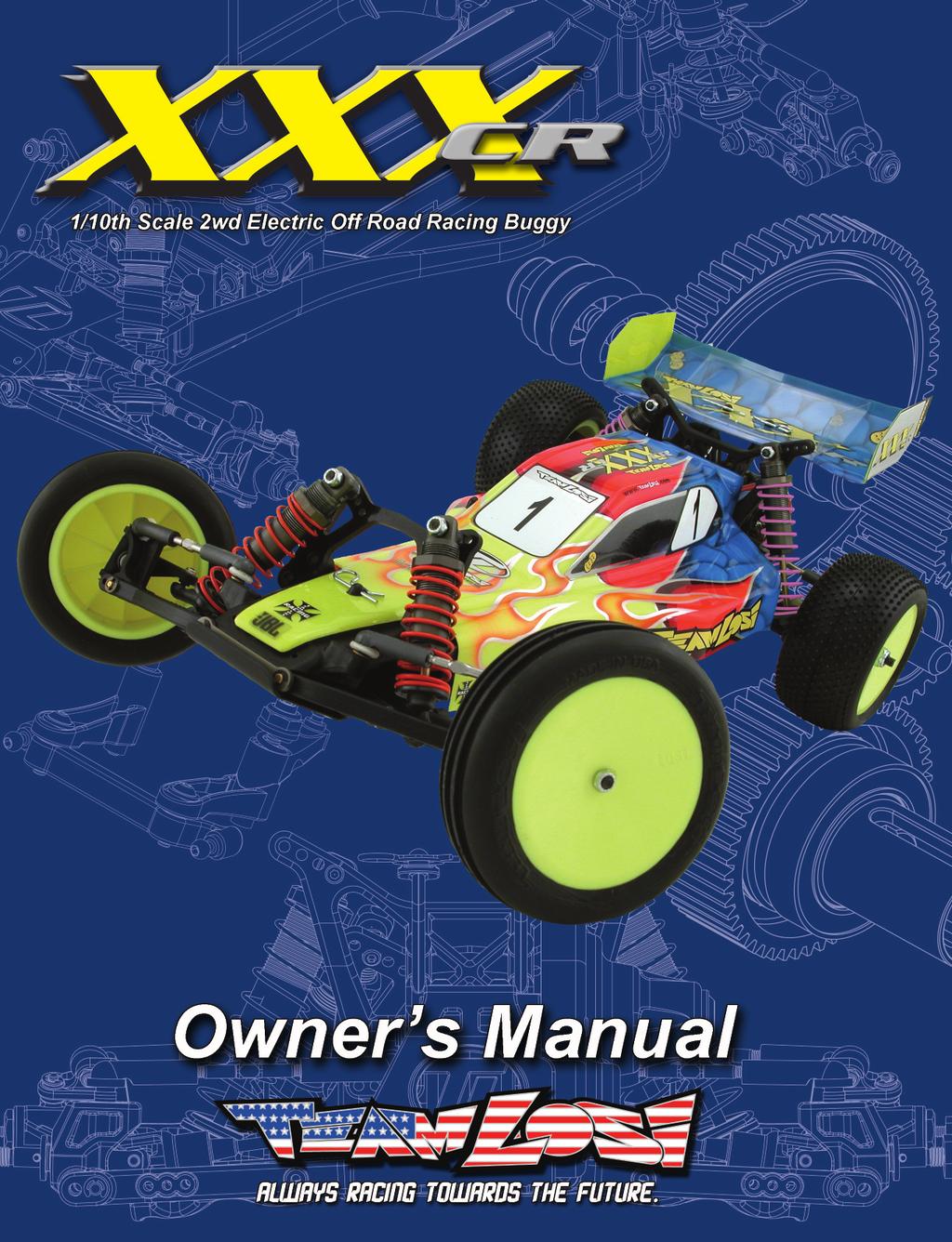
3 STEP I-01 Intro to the XXX-CR Manual INTRO Welcome Team Losi XXX-CR Owner! Thank you for selecting the XXX-CR as your new racing buggy. The XXX-CR has already distinguished itself as a top caliber racing chassis and as you will see, we have made every effort to produce a kit that is not only the most competitive but also easy to build and maintain. The simple bag-by-bag assembly sequence and easily followed instructions and drawings combined with Team Losi s world famous quality fitting parts will make building the XXX-CR a most enjoyable project. Before you open the first bag, or start assembly, please take a moment to read through the following instructions. This will familiarize you with the various parts, assembly tips, and descriptions as well as the tools needed. Taking an extra moment before starting can save a good deal of time and assure proper assembly. Good luck and good racing, Team Losi XXX-CR COMPLETED KIT SPECIFICATIONS Overall Chassis Length: 14-3/4in (378mm) Wheelbase: 10-1/2in (259mm) *Front Track Width: 9-7/8in (251mm) Overall Length w/tires: 15in (381mm) *Overall Height: 5-1/4in (133mm) *Rear Track Width: 9-3/4in (248mm) Note: Final kit weight will vary depending on accessories used. *All measurements taken at ride height (23mm). Table 1: XXX-CR Completed Kit Specifi cations. Kit/Manual Organization: The kit is composed of different bags marked A through F. Each bag contains all of the parts necessary to complete a particular section of the kit. Some of these bags have sub-assembly bags within them. It is essential that you open only one bag at a time and follow the correct assembly sequence, otherwise you may face difficulties in finding the correct part. It is helpful to read through the instructions for an entire bag prior to beginning assembly. Next to each of the step numbers is a check box. At the completion of each step, place a check in this box so that if you must stop and come back to the assembly, you will be able to pick up where you left off. For your convenience, an actual-size Hardware Identification Guide is included as a fold-out page at the back of this manual. Hardware that is not easily differentiable in each step is called out with an icon which contains a small picture of the part genre (referenced on the Hardware Identification Guide), the quantity of that part required for what is shown in the step, and the size or name of that part. To check a part, hold it against the silhouette until the correct part is identified. Associated with each of these parts, in the Hardware Identification Guide, is a LOSA-Number which is used when ordering replacement parts for your XXX-CR. In some cases, extra hardware has been supplied for parts that may be easy to lose. Components used in each step are identified by their relative LOSA-Number and the component s name. With the exception of a few parts, these are not referenced in the Hardware Identification Guide. The molded parts in Team Losi kits are manufactured to demanding tolerances. When screws are tightened to the point of being snug, the parts are held firmly in place. For this reason, it is very important that screws not be overtightened in any of the plastic parts. In some steps there will be a filled black circle with a white number. These indicate the specific order by which assembly must occur. In cases where steps are repeated (front/rear or left/right) these numbers may be omitted. Please note that these numbers will not call out every sub-step required for the step s assembly procedures, they will only highlight the critical order required for assembly. In each step, there are specific Detail Icons (shaped like a stop sign) that call out critical precautions or assembly tips for the process. There is a reference key that describes the meaning of each of the icons located on the fold-out Hardware Identification Guide at the back of this manual. To ensure that parts are not lost during construction, it is recommended that you work over a towel or mat to prevent parts from rolling away. IMPORTANT SAFETY NOTES: 1. Select an area for assembly that is away from the reach of small children. Some parts in this kit are small and can be swallowed by children, causing choking and possible internal injury; PLEASE USE CAUTION! 2. The shock fluid and greases supplied should be kept out of children s reach. They are not intended for human consumption! 3. Exercise care when using any hand tools, sharp instruments, or power tools during construction. 4. Carefully read all manufacturer s warnings and cautions for any chemicals, glues, or paints that may be used for assembly and operating purposes. i
 4-40 x 3/8 (A6229) 4-40 x 5/8 (A6248) 4-40 x 3/4 (A6205) 4-40 x 7/8 (A6226) 4-40 x 1/2 (A6256) 4-40 x 7/8 (A6216) 4-40 x 1 (A1133) 4-40 x 1-1/8")
 3/32 x.050 (A1122) 1/4 Standard Neck HD (A6026) 1/8 x.020 Stainless (A6350) 3/16 x.240 (A9941) 1/8 x 1/32 (.")
 (A5015) 3/16 x.")
 2.5mm x 12mm Solid (A6407) 3/32 x.")
 1/8 x 1.246 Solid (A6088) Body Clip (A8200) L 4-40 x 1/4 (A6308) 1/8 x 1.")
 L 10-32 x 3/8 (A6303) DETAIL ICON REFERENCE KEY 1 These numbers are used to identify the critical order in which assembly must occur.")
4 L HARDWARE Cap Head Flat Head Button Head Set 4-40 x 3/8 (A6206) 4-40 x 3/8 (A6210) 4-40 x 1/4 (A6234) 4-40 x 3/32 (A6248) 4-40 x 1/2 (A6204) 4-40 x 5/8 (A6233) 4-40 x 3/8 (A6229) 4-40 x 5/8 (A6248) 4-40 x 3/4 (A6205) 4-40 x 7/8 (A6226) 4-40 x 1/2 (A6256) 4-40 x 7/8 (A6216) 4-40 x 1 (A1133) 4-40 x 1-1/8 (A3034) 4-40 x 1-1/2 (A3034) 3mm x 6mm (A6238) Ball Studs Washers Metal Spacers Plastic Spacers.215 Standard Neck HD (A6025) Ball Stud (A6215) 3/16 x.100 (A3016) 3/32 x.050 (A1122) 1/4 Standard Neck HD (A6026) 1/8 x.020 Stainless (A6350) 3/16 x.240 (A9941) 1/8 x 1/32 (.0325 ) (A2127) 3/8 Standard Neck HD (A6027) 1/8 x 1/16 (.0625 ) (A5050).345 Short Neck HD (A6029) 1/8 x.030 Gold (A6350) 1/2 x.010 (A6230) 1/8 x.140 ( A ) (A5015) 3/16 x.140 (A3033) Ball Bearings Roll/Solid Pins Retaining Clips Nuts (Lock/Plain) 3/32 x 3/16 (A6912) 5mm x 8mm (A6907) 1/8 x 3/8 (A6909) 1/16 x 7/16 Roll (A6401) 2.5mm x 12mm Solid (A6407) 3/32 x.930 Solid (A6081) 3/32 E-Clip (A6103) 1/8 E-Clip (A6100) L 4-40 x 3/16 (Mini) (A6306) 4-40 x 1/4 (6300) 3/16 x 3/8 (A6916) 3/32 x Solid (A6082) 1/8 x Solid (A6088) Body Clip (A8200) L 4-40 x 1/4 (A6308) 1/8 x Solid (A6089) L 6-40 x 5/16 (A1610) 1/2 x 3/4 (A6908) 1/8 x Solid (A6092) L x 3/8 (A6303) DETAIL ICON REFERENCE KEY 1 These numbers are used to identify the critical order in which assembly must occur. *Note: They will not call out every stage of the assembly process. LOCTITE Apply Loctite CLEAR GREASE Apply Clear Grease GLUE Apply CA Glue GREASE Apply Synthetic White Grease OIL Fill With Silicone Oil Pre-Tap Pay Special Attention CUT Cut/Trim Ensure Free Movement Ensure Free Rotation Ensure Proper Orientation Push Firm L Side Shown L R R Assemble Other Side the Same Repeat/Build Multiple Screw Partially DO NOT Over Tighten/ Snug Tight Tighten 25

5 INTRO TOOLS REQUIRED FOR ASSEMBLY Team Losi has supplied all necessary Allen wrenches and a special wrench that is needed for assembly and adjustments. The following common tools will also be required: Needle-nose pliers, regular pliers, hobby knife, scissors or other body cutting/trimming tools, and a soldering iron may be necessary for radio installation. 3/16, 1/4, 5/16, and 11/32 nut drivers are optional. RADIO/ELECTRONICS A suggested radio layout is provided in this manual. Your high performance R/C center should be consulted regarding specific questions pertaining to radio/electrical equipment. HARDWARE IDENTIFICATION When in question, use the Hardware Identification Guide at the back of this manual. For screws, the prefix number designates the thread size and number of threads per inch (i.e., 4-40 is a #4 size thread with 40 threads per inch). The second number, or fraction, designates the length of the screw. For cap head and button head screws, this number refers to the length of the threaded portion of the screw. For flat head and set screws, this number refers to the overall length of the screw. Bearings and bushings are referenced by the inside diameter (I.D.) x outside diameter (O.D.). Shafts and pins are designated by type (Roll, Solid) and referenced by diameter x length. Washers, Spacers and Shims are described by inside diameter or the screw size that will pass through the inside diameter x the thickness or by their designated application (i.e., Ball Stud washer is primarily used under a Ball Stud). Retaining Clips are sized by the shaft diameter that they attach to or by type (Body). The Hardware Icon associated with E/C-Clips only designates the part genre of clips, not the actual part. Nuts come in four types, Non-Flanged, Flanged (F), Plain, and Locking (L) (designated on the Hardware Icons). The prefix number designates the thread size and number of threads per inch. The second number, or fraction, designates the size of the hex. For example, L 4-40 x 1/4 designates a Lock nut that will thread onto a 4-40 screw using a 1/4 nut driver. Ball studs are described by the length of the neck between the base and the bottom of the ball (i.e., standard, short) and the length of the threaded portion. TABLE OF CONTENTS SECTIONS 1. INTRODUCTION... i Kit/Manual Organization... i Important Safety Notes... i Tools Required for Assembly... ii Radio/Electronics... ii Hardware Identification... ii 2. Bag A: Front Clip Bag B: Chassis Bag C: Rear Clip Bag D: Transmission Bag E: Shocks Bag F: Final Chassis/Electronics Checklist Before Your First Run Setup Guide Blank XXX-CR Setup Sheet Hardware Identification Guide Filled-out XXX-CR Kit Setup Sheet...26 TABLES Table 1: XXX-CR Completed Kit Specifications... i Table 2: Servo Installation...4 Table 3: Motor Gearing...20 Team Losi is continually changing and improving designs; therefore, the actual part may appear slightly different than the illustrated part. Illustrations of parts and assemblies may be slightly distorted to enhance pertinent details. ii

6 STEP A-01 Steering Assembly BAG A STEP A-02 Kickplate Assembly Tighten the 6-40 x 5/16 Nut all the way down and then loosen it 2 full turns x 3/8 SOLID 3/32 x.930 1/8 x x 1/2 A1620 Spring Cap A1621 Idler Arm A1610 Servo Saver Spring Std..215 L 6-40 x 5/16 A4122 Steering Brace x4 3/32 x 3/16 A1233 Steering Bushing A1620 Servo Saver Top Std. 1/4 A1621 Steering Rack x3 L 4-40 x 3/16 A1621 Servo Saver Bottom A1610 Steering Post A4122 Kickplate STEP A-03 Front Suspension Assembly A4129 Front Pivot A1122 Spindle Carrier, Left SOLID 3/32 x x4 3/32 E-Clip 1/8 E-Clip 3/32 x.050 L 4-40 x 3/16 SOLID 1/8 x A9956 Hinge Pin Brace A1112 Front Arm A1122 Spindle, Left 3/16 x 3/8 SOLID 3/32 x.930 3/16 x.100 Std. 1/4 A1133 Front Axle L 1

7 STEP A-04 Front Bulkhead Assembly BAG A 4-40 x 1/4 x x 3/8 A1104 Shock Tower, Front 4-40 x 3/4 Std. 3/8 Ball Stud A4122 Bulkhead, Front STEP A-05 Front Clip Assembly 4-40 x 3/8 A4118 Front Bumper 4-40 x 5/ x 7/8 2
8 STEP A-06 BAG A Tierod Assembly and Installation Use the Team Losi flat wrench to hold the Turnbuckle while installing the Ball Cups. Be sure to install the assembled Tierod onto the car with the groove (next to the center square section) on the driver s left side for easier adjustment later. Front Camber Tierod (71.6mm) (2.819in) A6003 Foam Thing (73.0mm) (2.874in) Steering Tierod A6016 Ball Cup L STEP A-07 Completed Front Clip Assembly 3
9 STEP B-01 Servo Assembly BAG B JR Airtronics Servo Manufacturer, Make/Model Mount Position Servo Horn All (DZ9000T/S DOES NOT FIT) 1 23T 94357Z, 94358Z, 94649Z, 94360Z, 94452Z, 94758Z, 94737Z, 94738Z 94102Z, 94112Z T Hitec All 1 24T Futaba KO All (S9102 DOES NOT FIT) 2 25T 2 PDS-2123, 2344, 2363, 2365, Table 2: Servo assembly and installation. Ensure the servo gear is centered before attaching the Servo Horn. This is best accomplished by connecting the servo to the radio system and setting the trim to center. Install the Servo Mounts in the orientation corresponding to the numbered diagram to the above right and Table 2. DO NOT tighten the four 4-40 x 3/8 Cap Head Screws all the way, they must be tightened after assembly to the Chassis is complete to ensure proper alignment. 23T Servo Screw (Not Supplied) L 4-40 x 3/16 Ball Stud x4 1/8 x.030 Std..215 A1620 Servo Horn (See Table 2) A1620 Servo Mount x x 3/8 Servo (Not Supplied) STEP B-02 Servo Installation First place the Servo into the Chassis and place the Chassis Stiffener on top to ensure the servo is centered in-between the Mounts and as low as possible. Remove and tighten the four 4-40 x 3/8 Cap Head Screws and continue with the installation. A4105 Chassis Stiffener x x 3/8 A4105 Chassis 4
10 STEP B-03 Chassis Assembly BAG B Steering Link 4-40 x 3/8 A4123 Body Mount (1.374in) (34.9mm) A6010 Ball Cup, Short A6265 Threaded Insert The Steering Link length will vary depending on the brand and model of Servo used. This length is only a starting point and will most likely need to be adjusted in Step F-01. STEP B-04 Completed Chassis 5
11 STEP C-01 Dogbone Assembly BAG C A3081 Dogbone A3083 Universal Yoke 4-40 x 3/ A3027 Bearing Cross Install the Yoke onto the Cross Ball pins by first inserting one pin of the Ball into one ear of the Yoke at a slight angle. Gently spread the ears of the Yoke and slip the second ear of the Yoke over the remaining pin on the ball x 3/32 2 SOLID 2.5mm x 12mm A3015 Rear Axle STEP C-02 Rear Hub Carrier Assembly 1 Std. 3/8 Ball Stud x /16 x 3/8 4 ROLL 1/16 x 7/16 A2129 Rear Hub Carrier 3/16 x.240 A9941 Axle Spacer L 6
12 STEP C-03 Rear Suspension Assembly BAG C A2113 Rear Pivot 1/8 x.020 CAUTION! The Rear Arms are marked with dots to designate the orientation. Note that 1 dot is for the left and 2 dots is for the right side. 1/8 x 1/16 A4139 Forward, Rear Pin Brace SOLID A2132 Rear Arm 1/8 x x4 1/8 E-Clip SOLID 1/8 x STEP C-04 Rear Bulkhead Assembly STEP C-05 Rear Plate Assembly x x 1/ x 1/4 A2100 Rear Bulkhead/ Shock Tower 4-40 x 7/8 Short.345 A4221 Wing Mount A2106 Pivot Plate x x 3/8 7
13 STEP C-06 BAG C Tierod Assembly and Installation Use the Team Losi flat wrench to hold the Turnbuckle while installing the Ball Cups. Be sure to install the assembled Tierod onto the car with the groove (next to the center square section) on the driver s left side for easier adjustment later. Rear Camber Tierod (3.074in) (78.1mm) A6003 Foam Thing A6016 Ball Cup L STEP C-07 Completed Rear Suspension 8
14 STEP D-01 Differential Assembly BAG D Apply a small amount of Clear Diff Grease to both Diff Outdrives and the Diff Ring Shims before installing the Diff Rings. Apply enough Clear Diff Grease to the top side of the Diff Rings, or to both sides of recessed Ball section in the Diff Gear (after Diff Balls are installed) to cover the Diff Balls when the Diff is assembled. Assemble the Diff and tighten until some resistance is felt, see the Final Checklist and Setup Guide for final Diff adjustment procedures. 5mm x 8mm 4 A3038 Outdrive, Female Large Center Hole A3018 Thrust Bearing 5 2 A6951 Diff Balls, Carbide A3036 Diff Gear, 51T A3039 Diff Ring (Chrome) A3039 Diff Ring Shim (Bronze) A3038 Outdrive, Male Small Center Hole A3078 Foam Diff Seal A2908 Diff Spring The Diff Ring Shims are optional. If you choose not to use them (See Setup Guide), you must install the smaller Diff Shims on the outside of the Diff before installing the Diff into the Gearbox case. A3078 Diff Screw 3 1 A2911 Diff Nut STEP D-02 Transmission Assembly A3041 Motor Plate A3033 Gearbox, Right A2937 Idler Shaft 3/16 x.140 A3079 Idler Gear A9930 Top Shaft 3/16 x 3/8 A3033 Gearbox, Left 4-40 x 3/8 1/8 x 3/8 The Diff Ring Shims are optional. If you choose not to use them (See Setup Guide), you must install the smaller Diff Shims on the outside of the Diff before installing the Diff into the Gearbox case. 1/2 x 3/4 A x 5/8" Cap Head Screw 4-40 x 1-1/8 9
15 STEP D-03 Slipper Clutch Installation BAG D 4-40 x 1/4 A3132 Slipper Plate A4123 Motor Guard A3123 Slipper Pad A3981 Spur Gear, 78T A3124 Spring Spacer A3125 Slipper Spring A3135 Spring Retaining Washer L 4-40 x 1/4 STEP D-04 Motor Installation Motor (Not Supplied) When setting the gear mesh, leave a small amount of backlash for proper function. Too much backlash will cause failure, so be sure to check the mesh at different points in the rotation of the Spur Gear. A3042 Gear Cover Pinion Gear (Not Supplied) 1/8 x.030 3mm x 6mm A3043 Gear Cover Plug x x 3/8 10
16 STEP D-05 Transmission Installation BAG D 4-40 x 1-1/2 Ball Stud 4-40 x 3/8 CAUTION! Ensure the Dogbone is inserted into the slot in the Outdrive before installing the Transmission. STEP D-06 Completed Rear Clip Assembly 11
17 STEP E-01 Shock Assembly BAG E Match short front Shock Bodies with assembled short front Shock Shafts and long rear Shock Bodies to assembled long rear Shock Shafts. Holding the shock body inverted, fill the Shock Body with Shock Oil up to the bottom of the threads inside the Shock Body. Insert shaft assembly with cartridge against the shock piston. Slowly tighten the Cartridge until it bottoms against the Shock Body. Do not tighten all the way. Slowly push Shock Shaft assembly into the Shock Body. This will bleed the excess oil out of the Shock. Once the Shaft is pushed all the way down into the Shock Body, tighten the Shock Cartridge the rest of the way with a 7/16 wrench or a pair of pliers approximately 1/8th of a turn. There should be no air in the Shocks as you move the Shaft in and out of the Shock Body. If there is; you will need to add some Oil and repeat the bleed process. If the Shock does not compress all the way, the shock has too much Oil. Simply loosen the Cartridge about 1/4 turn and push the Shaft into the Body and retighten the Cartridge. A9940 Ball Joint A5023 Shock End A5054 Shock Body, Front A5055 Shock Body, Rear A5064 Shock Shaft, Rear A5015 Shock Cartridge A5060 Shock Shaft, Front 1/8 x 1/32 1/8 x A5049 Shock Adjustment Nut x4 1/8 E-Clip A5046 Shock Piston, #56 (Red) A5129 Spring, Front (Orange) A5150 Spring, Rear (Pink) A5079 Spring Cup 12
18 BAG E STEP E-02 Front Shock Installation STEP E-03 Rear Shock Installation L 4-40 x 1/4 A5013 Shock Bushing, Long A5013 Shock Bushing, Short L 4-40 x 1/ x 1/ x 1/2 STEP E-04 Completed Front and Rear Clips 13
19 STEP F-01 BAG F Front and Rear Clip Installation The Servo Link installed in Step B-02 was set to an approximate length. The correct length will vary depending on the type of servo used, the radio settings, and the Servo Horn. It may be necessary to adjust this length, after all radio gear is installed and the servo is centered properly, to obtain the maximum steering throw and have the Steering Bellcranks centered without having extreme trim settings on the radio. x x 3/ x 1/2 x x 3/8 STEP F-02 Speed Control Installation STEP F-03 Receiver Installation Speed Control (Not Supplied) A4003 Antenna Tip Cover Receiver (Not Supplied) A4002 Antenna Tube A4004 Double-Sided Tape A4004 Double-Sided Tape 14
20 STEP F-04 Battery Installation BAG F A4114 Battery Strap A4116 Battery Pad 1 3 This configuration is for use with a stick type battery back. 2 A4114 Battery Spacer Foam Body Clip STEP F-05 Tire Mounting Using a pair of sharp scissors, carefully cut the inside corners of the Tire Foams away to allow for easier mounting on the Wheel as shown below. Ensure there is no flashing on the bead of the Tires, if so, trim it away to allow for easier mounting on the Wheel. A7368R Rear Tire, Big Shot A7398 Rear Tire Foam Foam Cross Section A7104 Rear Wheel 1 A7204R Front Tire, Extra-Wide Body 2 A7297 Front Tire Foam A7004 Front Wheel 15
21 STEP F-06 Tire Gluing BAG F The Tires need to be glued to the wheels. This can be done by using a fast-curing super glue or cyanoacrylate glue (LOSA7880, LOSA7881), available at your local hobby shop. Install a Tire gluing rubber band around the outside of the Tire, in line with the bead to hold it onto the Wheel. Now slightly pull back the tire bead from the wheel and apply a thin bead of glue between the Tire bead and the Wheel all the way around, wait for this side to dry and do the same to the other side until the Tire is firmly adhered to the Wheel. Allow the glue to dry thoroughly before continuing. STEP F-07 Tire Installation L x 3/8 L 4-40 x 1/4 When installing the mounted Tires, be sure to align the pin or hex feature in the Wheels with the pin or hex on the Axles before tightening the Nuts. 16
22 STEP F-08 Body and Wing Painting BAG F Painting: Prepare the Lexan Body and Wings for painting by washing them thoroughly (inside and out) with warm water and liquid detergent. Dry both the Body and Wings with a clean, soft cloth. Use the supplied Window Masks to cover the windows from the inside. A high-quality masking tape should be used on the inside of the Body to mask off any stripes, panels, or designs that you wish to paint on the Body or Wings. Use acrylic lacquer or other paints recommended for Lexan (polycarbonate). (NOTE: LEXAN R/C CAR BODIES ARE MEANT TO BE PAINTED FROM THE INSIDE!) Apply paint to the inside of the Body and to the under-side of the Wings. Remove the masking tape for the next color and continue. Try to use darker colors first. If you use a dark color after a light color, apply a coat of white paint over the lighter color before applying the darker color, or if you are painting over white, coat it with silver. This will help prevent the darker color from bleeding through the lighter color. Mounting: After painting, trim the Body along the trim lines as shown below, emphasized by the dark shading in the figure below. There is an indented trim line around the Body which can be used as a guide for trimming. Make four 1/4 -diameter holes at the locations marked with dimples. There are two on the back of the Body and one on the right side of the Body. Also trim the oval shaped hole on the front of the Body. These will be the Body mounting and Antenna holes. Now trim the rear Wings along the trim lines shown below. Drill two 7/64 diameter holes in the dimples of both rear Wings. With the Wings painted and completely trimmed, mount the rear Wings to the Wing Mounts using two Body Clips. The shown Wing Washers (see Step F-09) are only necessary if the optional small rear Wing is not used. Stickers: After the Wings and Body are mounted, REMOVE THE PROTECTIVE FILM ON THE OUTER SURFACE, now you can apply the stickers. Cut the stickers from the sticker sheet that you wish to apply to the Body or Wing. Before removing the protective backing, find the desired location. Remove the backing completely and reattach an edge of the sticker to the shiny side of the backing material. Using the rest of the backing material as a handle, position the sticker and press firmly into place to complete its application. Front Wing 17
23 STEP F-09 Body and Wing Mounting BAG F A6016 Wing Mount Washer x5 Body Clip Optional Front Wing Install on top of Body and behind Shock Tower. Secure with the front Body Clip 18
24 CHECKLIST BEFORE RUNNING YOUR NEW XXX-CR OFF-ROAD RACING BUGGY for the first time, you should run down the following checklist in order and complete the listed tasks. We re sure you re anxious to get out and run your new XXX-CR now that its built, but please note that fine tuning of the initial setup is an essential part of building a high performance racing buggy such as your new XXX-CR. Following this simple Checklist and the Team Tips will help to make the first run with your new car much more enjoyable. 1. Breaking in the Differential: While holding the chassis with only the left side tires firmly on the ground, give the car about one quarter throttle, for 10 seconds. The right side tires should spin freely during this time. Repeat this with only the right side tires held firmly to the ground, allowing the left tires to spin. Feel the differential (diff) action and tighten slightly, if necessary. The differential should have a tight, thick feel when rotating it after final adjustment. CAUTION! YOUR DIFFERENTIAL SHOULD NEVER BE ALLOWED TO SLIP WHEN RUNNING (A SLIPPING DIFFERENTIAL CREATES A BARKING SOUND). IF IT DOES, STOP IM- MEDIATELY AND TIGHTEN TO PREVENT DAMAGE. SEE DIFFERENTIAL ADJUSTMENT AND SLIPPER ADJUSTMENT IN THE SETUP GUIDE. 2. Check for free suspension movement: All suspension arms and steering components should move freely. Any binds will cause the car to handle poorly. 3. Set the ride height: Set the ride height on the rear so the dogbones are level (parallel) to the ground by adjusting the shock adjustment nuts, effectively increasing or decreasing pre-load on the springs. See the Setup Guide for additional information on ride height adjustment. 4. Set the camber: Adjusting the camber tierod length changes the amount of camber. Using the Team Losi flat wrench to adjust the tierods once installed. Rotating the tierods towards the front end of the vehicle will shorten the length, increasing negative camber. Rotating the tierods towards the back of the car will lengthen them, increasing negative camber. Set the front tires to have 1 degree of negative camber and ensure that they are adjusted equally, left to right. Set the rear tires to have.5-1 degrees of negative camber and ensure that they are adjusted equally, left to right. 5. Set the front toe-in: Adjust the front steering tierods so that when the servo is centered on the transmitter, the front tires are both pointing straight. Refer to the Setup Guide for more information on toe-in/out. 6. Charge a battery pack: Charge a battery pack as per the battery manufacturer s and/or charger manufacturer s instructions so that radio adjustments can be made. Never plug the battery into the speed control backwards. 7. Adjust the electronic speed control (ESC): Following the manufacturer s instructions, adjust your speed control and set the throttle trim on your ESC so that the car does not creep forward when no transmitter input is applied. Make sure that there is not too much brake being applied when the trigger/stick is in the neutral position. Some speed controls have a high/low setting for the throttle and brake. 8. Set the transmitter steering and throttle trim: The steering trim tab on the transmitter should be adjusted so that the car rolls straight when you are not touching the steering wheel/stick. If the servo and steering link were installed correctly, the wheels should turn equally to the left and right. If this is not the case, refer to Table 2 and ensure that the steering servo and horn were properly installed. Also check the Steering Link Length as noted in Step F-01. Make sure the throttle trim is set so that the motor does not run when in the neutral position. You may wish to run one click of brake to be safe. TIPS AND HINTS FROM THE TEAM Before you start making changes on your XXX-CR Off Road Racing Buggy, you need to make a few decisions. Tires, and how they are setup, have a tremendous impact on overall performance. Before you start making changes on the chassis setup, take a movement to observe a few of the fastest cars at the track and what type of tire and inner liner they are running. When making chassis changes, you should first decide where you feel the car needs to be different. This is commonly referred to as changing the balance. First decide if the front of the car needs to be adjusted or the back. You will want to work with the rear if the car enters the turn with the front end sticking, and tracking well, while the rear end either does not want to follow, or simply doesn t know what it wants to do. The opposite is true if the rear end seems to want to push the front end through the corners or if the front drives into the corner uncontrollably. You will notice that several different adjustments have similar effects on the handling as well. You will find the best adjustment will become a personal decision based on the feel that each of these adjustments yield. This also reflects on the balance we referred to earlier. Never make more than one change at a time; if the change you made works adversely, or doesn t address your need, return to the previous position and try something else. Team Losi s development team has put hundreds of hours on the XXX-CR to arrive at the setup we put in the instruction manual. If you find that you have lost the handle go back to the kit (stock) setup, as this setup has proven to be reliable, consistent, and easy to drive. All of us at Team Losi are sure that you will find the XXX-CR Off Road Racing Buggy to be the most versatile and easiest car to drive fast, with great consistency. We hope the information in the following guide helps you to enjoy your XXX-CR Buggy, and racing it, as much as we do. For the latest in setup and accessory parts information, visit the Team Losi web site at: regularly. For any technical questions go to the Meet the Team section of the site. We will try to answer your questions in the order received, to the best of our knowledge, by our own Team Losi R&D race team. Please check the Team Losi web site periodically to find out new setup information as we are always testing on all types of tracks and surfaces. Also note, that there are many ways to setup a car. The rules we follow can reverse sometimes with different driving styles or different setup styles, so test for yourself and you will find a setup that works right for you. 19
25 SETUP GUIDE Tuning the Transmission of the XXX-CR Differential Adjustment: Never allow the diff to slip; that s what the slipper is for. Before trying to adjust your diff, you need to tighten the slipper until the spring is fully compressed. Next, hold the spur gear and right rear tire, then try turning the left rear tire forward. It should be very difficult to turn the left rear tire. If the tire turns easily, the diff is too loose. To tighten the diff, line up the slot in the diff screw with the groove in the left out drive. Place the 1/16 Allen wrench through both of these slots. This will lock the diff screw and the out drive together. While holding the Allen wrench in place, turn the right rear tire forward about 1/8 of a turn. Check the differential adjustment again and repeat the tightening process as necessary until the differential is no longer slipping. See Slipper Adjustment below, and then continue from here. The final differential adjustment check should be made by placing the car on carpet, grass, or asphalt and punching (quickly applying) the throttle. The differential should not slip. If it does, tighten the diff in 1/8-turn increments as described above until the slippage stops. Once the diff has been adjusted, it should still operate freely and feel smooth. If the diff screw starts to get tight before the diff is close to being adjusted properly (based on slip), the diff should be disassembled and inspected; you may have a problem with the differential assembly. Refer to the assembly instructions to ensure that the diff is properly assembled and that all parts are properly seated in the assembly. Motor Gearing: The important thing is to keep the motor in its optimal RPM range as much as possible around the entire track. This will depend on the straight-away length and the size of the infield turns. The chart below is a guide to give you a starting point. You may want to try gearing up (larger pinion or smaller spur) or down (smaller pinion or larger spur), one size at a time, noting the straight-away speed and acceleration through the infield. *NOTE: OVER GEARING (TOO LARGE OF A PINION OR TOO SMALL OF A SPUR) CAN CAUSE DAMAGE TO BOTH YOUR ELECTRONICS AND MOTOR. USE CAUTION WHEN SELECTING YOUR GEARING. Gear Ratio Calculation: The XXX-CR includes a 78-tooth, 48-pitch Kevlar spur gear. The overall internal drive ratio of the transmission is 2.43:1. The pinion gear that is used will determine the final drive ratio. To calculate the final drive ratio, first divide the spur gear size by the pinion gear size. For example, if you are using a 21-tooth pinion gear, you would divide 78 (spur gear size) by 21 (pinion gear size); 78/21=3.71. This tells you that 3.71 is the external drive ratio of the transmission. Next, multiply the internal drive ratio (2.43) by the external drive ratio (in this case 3.71). 2.43x3.71=9.02. This means that by using a 21-tooth pinion gear with a 78-tooth spur gear, the final drive ratio is 9.02:1. Consult your high-performance shop for recommendations to suit your racing style and class. The chart below lists some of the more common motor types and a recommended initial gearing for that motor. Ratios can be adjusted depend on various track layouts, tire sizes, and battery types. Stock Motor Modified Motor Motor Manufacturer, Make/Model Spur Pinion EPIC Based Monster EPIC Based Binary (Two Magnet) EPIC Based Binary (Four Magnet) EPIC Based P2K/P2K TOP Based (Standard Brush) TOP Based (V2) Yokomo Based All 19 Turn Turn Turn Turn Turn Turn Turn Table 3: Suggested gearing. Tuning the Front End of the XXX-CR Shock Location: The XXX-CR has four mounting locations on the front shock tower. The position can be easily adjusted by simply moving the top of the shock to another hole. The standard location (third hole out in the tower) works best on most tracks. Moving the top of the shock out one hole will result in an increase in steering and the car will react quicker. Moving the top of the shock inward a hole will slow steering response time and make the car smoother in bumps. The standard position on the arm is middle which offers the best balance from track to track. When using the inside shock position you will want to move the shock in on the tower to keep the angle same angle as the stock location. A stiffer spring will be needed when using the inside shock location to obtain the same roll stiffness. Running the inside shock location will give the car more steering into the turn and less steering on corner exit. Running the shock location outside on the front arm will give you less overall steering into the turn and keep the front end flatter through the turn making the car smoother and easier to drive. This can be used on high bite tracks. Keep in mind as you move the shocks in on the arm will require internal limiters to obtain the correct suspension travel. For the inside location a.090 limiter works great. Team Losi sells a shock spacer set (LOSA5050) that includes.030,.060,.090, and.120 spacers. Static Camber: This refers to the angle of the wheels/tires relative to the track surface (viewed from either the front or back). Negative camber means that the top of the tire leans in toward the chassis. Positive camber means the top of the tire leans out, away from the chassis. Camber can be precisely measured with after market camber gauges, sold at a local hobby shop. It can be measured (roughly) using any 20
26 SETUP GUIDE square (to the ground) object by checking the gap between the square edge and the top of the tire. Testing has shown that 1 degree of negative camber is best for most track conditions. Increasing negative camber (in the range of 1-2 degrees) will generally increase steering. Decreasing negative camber (in the range of 0-1 degree) will generally decrease steering and the car will feel easier to drive as a result. This is, most often, a very critical adjustment in tuning your car that can be made track-side! Inboard Camber Location: The XXX-CR has three different inner locations with vertical adjustment for the front camber tie rod. In general, the lower or further out the inside position is, relative to the outside, the more camber gain (total camber change through the total throw of the suspension) is present. This is an adjustment that is difficult to make a generic statement for as it can have slightly different results on various conditions. The following is a summary of how this adjustment will usually impact the handling of the XXX-CR. A longer front camber link will usually make the car feel stiffer. This will help keep the car flatter with less roll, but can make the car handle worse in bumpy conditions. A shorter front camber link will result in more front end roll. This will increase high-speed steering and make the car better in bumps. Too short of a front link may make the car feel twitchy or wandery meaning that it may be difficult to drive straight at high speed. Inboard Camber Vertical Adjustment: Washers are often used under the inner ball stud mounting location; this is one of the most important adjustments on the XXX-CR car. You should get a feel for how the number of washers affects the handling. Adding washers will make the car more stable and keep the front end flatter. Removing washers will make the steering more aggressive. This can be good in some conditions, but can also make the car difficult to drive in others. The best all-around adjustment is with one washer as per the assembly instructions. The washers that are used are included in a assortment package of washers (LOSA6350). Outboard Camber Location: In addition to the inboard camber location the XXX-CR also provides outboard mounting options. The outer location is the most used as it keeps the car flatter with less roll. The outer location also helps the car stay tighter in turns with a more precise steering feel. Moving the link to the inner hole will make the steering react slightly slower. The advantage to the inner hole is that it can increase on power steering and help the car get through bumps better. Toe-In/Out: This is the parallel relationship of the front tires to one another. Toe-in/out adjustments are made by changing the overall length of the steering tie rods. Toe-in (the front of the tires point inward, to a point in front of the front axle) will make the car react a little slower, but have more steering from the middle of the turn, out. The opposite is true with toe-out (the front of the tires point outward, coming to a point behind the front axle), the car will turn into the corner better but with a decrease in steering from the middle of the turn, out. Toe-in will help the car to track better on long straights, where as toe-out has a tendency to make the car wander. Bump-In/Out: Bump-out (front of the front tires toe-outward under suspension compression) will result in more off-power steering. This effect is obtained by adding washers under the steering spindle ball stud. Bump-In (front of the front tires toe-inward under suspension compression) will result in less off-power steering and running too much bump-in can make the steering feel very inconsistent. This effect is obtained by installing a ball stud washer on the bottom of the spindle. Testing has shown that running zero bump steer (kit setup) in the XXX-CR offers the best overall setup. Caster: This is the angle of the kingpin from vertical when viewed from the side of the car. The XXX-CR comes equipped with 30-degree spindle carriers, however, this can be adjusted to 25-degrees with aftermarket carriers (LOSA1123). Total caster is determined by adding the amount of kick up (XXX-CR has 30-degrees) and the kingpin angle of the front spindle carriers. Increasing total caster will provide more steering entering a turn but less on exit. Decreasing total caster will cause the steering to react faster and increase on-power steering. Variable Length Arm and Carrier: The front arms of the XXX-CR have the option to have different front arm lengths. The stock position is the short arm length which gives the car the best balance for most tracks. For most tracks the standard setup will work well, but for extremely bumpy, rutted, and high bite tracks the longer arm length will help slow the reactions of the car making it feel less twitchy and more stable. For the long front arm length, the spring rate will need to be increased to a blue front spring (3.8lb-LOSA5134) to have the same roll stiffness as the stock settings. The oil will also need to be increased from the stock setting of 27.5wt. oil to 32.5wt. to keep the same static dampening. Tuning the Rear End of the XXX-CR Shock Location: Moving the top of the shocks outward (from the stock settings) on the tower will provide less rotation in a corner and the car will become more responsive with increased forward traction. This will also help keep the car from bottoming out on big jumps. Moving the shocks out on the arm will result in less forward traction and let the car carry more of an arc through the exit of the turn. In general, when changing shock locations on the arm, it will be necessary to go down one spring rate when moving out on the arm. Static Camber: Having the same definition as for the front end and measured in the same fashion, rear camber can also be a critical tuning feature. Testing has shown that running a small amount of negative camber (.5-1 degree) is best. Increasing negative rear camber (in the range of degrees) will increase stability and traction in corners, but decrease high speed stability. Decreasing rear camber (in the range of degrees) will decrease stability and traction in corners, but will increase high speed stability. Inboard Camber Location: The XXX-CR has multiple rear camber locations. Using a longer camber link will improve stability and traction (grip). Using a shorter camber link will increase steering while decreasing rear grip. Running the camber link in the inside position (1) on the shock tower will give your car more steering entering the turn as it will let the car set over the rear tire and give you more forward traction exiting the turn. As you move the camber link towards the outside of the car you will gain less initial steering however you will gain more steering as the car exits the turn. The XXX-CR now has the capabilities of a lower row of holes in the rear shock tower for the inner camber link location. The lower holes gives the car more camber gain (more angle relative to arm = more camber gain). This can be helpful when tracks get bumpy and rutted to help the rear end of the car go through the bumps easier due to the increased camber gain of the tires. 21
27 SETUP GUIDE Outboard Camber Location: Running the camber link in the inside position (A) on the hub will generate more rotation entering a turn, but decrease steering on exit. Running the camber link in the furthest outer position (C) on the hub will generate more stability entering a turn and increase steering on exit. Outboard Camber Vertical Adjustment: New to the XXX-CR is the vertical mounted ball stud on the hub. Washers are often used under the outer ball stud to determine the height of the ball stud. Raising the height of the ball stud increases camber gain while lowering the height of the ball stud decreases camber gain. Testing has shown that running the inboard rear camber ball stud in a higher location (less angle relative to arm = less camber gain) on high traction surfaces offers improved stability with decreased rear grip. Also, on low traction surfaces, running the inboard rear camber ball stud in a lower location (more angle relative to arm = more camber gain) will increase rear grip. Toe-In: Having the same definition as for the front end, the toe-in can be adjusted on the XXX-CR with the rear hubs. The stock toe-in is 3 degrees of inboard per side and 0 degrees in the hub. Increasing rear toe-in will increase forward traction and initial steering, but reduce straightaway speed. Decreasing rear toe-in will decrease forward traction and free-up the car. Less toe-in can be used for stock racing to gain top speed. Anti/Pro-Squat: In the stock configuration, the XXX-CR has 2 degrees of anti-squat. Increasing anti-squat is generated by raising the front of the pivot block, relative to the rear of the pivot. This will increase initial steering and forward traction. You can increase anti-squat in 1 degree increments by using two.030 washers between the front of the pivot plate and pivot block. Pro-squat is generated by raising the rear of the pivot relative to the front. This will decrease forward traction and initial steering, but provide more on-power steering on high traction tracks. Pro-squat will also help the car from pulling wheelies on high bite surfaces. Also available is an aftermarket part that is a 0 degree rear pivot block (LOSA2112), if pro-squat is desired it is best to start with this option. Variable Length Arm and Carrier: Like the front of the XXX-CR, the rear end also has variable length arms and carriers. The stock setting is in the short arm location which offers the best balance for most tracks. Moving the hinge pin to the outer location of the arm and hub will give a long arm setting which is suitable for tracks where less rear traction is needed. This can be used on high bite tracks to help settle the car down from the rear end. For the long rear arm length, the spring rate will need to be increased to a red rear spring (2.6lb-LOSA5152), The oil will also need to be increased from the stock setting of 27.5wt. to 32.5wt. oil to keep the same static dampening. Tuning the Chassis of the XXX-CR Slipper Adjustment: This should be done after the diff is properly adjusted. If you have just finished adjusting the differential, loosen the slipper adjustment nut four full turns. This will be a good starting point for your slipper settings. Ride Height: This is the height of the chassis in relation to the surface of the track. It is an adjustment that affects the way your car jumps, turns, and goes through bumps. To check the ride height, drop one end (front or rear) of the car from about a 5-6 inch height onto a flat surface. Once the car settles into a position, check the height of that end of the car in relationship to the surface. To raise the ride height, lower the shock adjuster nuts on the shock evenly on the end (front or rear) of the car that you are working on. To lower the ride height, raise the shock adjuster nuts. Both left and right nuts should be adjusted evenly. You should start with the rear ride height where the car comes to a rest at a height where the dog bones are slightly below level with the surface. The front ride height should be set so that the bottom of the chassis is level with the surface. Occasionally, you may wan to raise the front ride height to get a little quicker steering reaction but be careful as this can also make the car easily flip over. Every driver likes a little different feel so you should try small ride height adjustments to obtain the feel you like. We have found that ride height is really a minor adjustment. This should be one of the last adjustments after everything else has been dialed in (tuned). Do not use ride height adjustment as a substitute for a change in spring rate. If your car needs a softer or firmer spring, change the spring. Do not think that simply moving the shock nuts will change the stiffness of the spring; it will not! Battery Position: This is a critical adjustment that is often overlooked but can be very useful. Start by running the battery spaced forward (kit setup). Moving the battery back can improve rear traction on slippery surfaces. Moving the battery back too far can cause the rear end to swing through turns on some tracks. This is a result of having the weight too far back. The XXX-CR comes equipped with one foam battery spacer. This can be cut in half (lengthwise and carefully) to split the difference when adjusting the battery position, hence offering a middle position when either extreme is inadequate. Camber Rise Relationship: The XXX-CR setup out of the box comes with less front camber gain than the rear camber gain. The reason for this is that less front camber lets the front end drive flatter and makes the car more stable. By having more camber gain in the rear gives the car more rear traction and helps the rear tires accelerate through the bumps and ruts. Steering: The XXX-CR has incorporated a new Ackermann steering link that provides reverse Ackermann. The reverse Ackermann gives the car a smoother steering response into the turn with more steering on corner exit and helps keep the car consistent during changing track conditions. The new Ackermann link will help the front of the car stay flatter through the turn and also help the front end from getting grabby on rutted/bumpy tracks. By adding a.030 washer to the ball studs on the link will result in less reverse Ackermann and will give the car more steering into the turn but less steering on corner exit. Front Wing/Rear Wing Setup: Another tuning option included with the XXX-CR is done with down force with a new front and rear wing set. Included in the kit is a front wing that when installed will give the car more down force onto the front end that will result in more overall steering. This can be used on high traction tracks where a greater amount of steering is needed. On the rear of the car is a new wing that is ½ wider than the existing rear wings that have proceeded in the previous XXX kits. The larger rear wing adds more stability needed with 22
28 SETUP GUIDE the ever growing voltage of batteries and advances in brushed and brushless motors that increase the speeds of the car. On the rear wing there are two scribe lines on the rear of the wing for a wicker bill. A wicker bill is used for added rear down force. Running a larger rear wicker bill will achieve more stability while not taking away much steering from the car. A new inner wing can be installed to add more stability and rear traction to the car. From track to track it is recommended to have a few different wings on hand with different size wicker bills to find the correct down force needs. Plastic Outdrives: Plastic out drives (LOSA3097) can be used on your XXX-CR to gain more acceleration due to the low weight of the plastic outdrives (roughly 30% lighter than the standard steel outdrives) which can be ideal for Stock and 19T racing. The plastic outdrives also reduce the friction of the dog bone pin as it plunges in and out of the outdrive under suspension compression and rebound. The reduction of friction gives the car less rear traction as a result. Graphite Components: Graphite components are available for the XXX-CR and can be used as a tuning option at times. The graphite components give the car less flex which result in a more reactive car. The graphite parts also make the car lighter in overall weight. Plastic parts offer some more flex which tend to make the car easier to drive on lower traction and bumpy tracks. The plastic parts that have been supplied in the kit offer the best all around balance from track to track. Diff Shims: The XXX-CR comes with differential shims that go in between the diff out drive and diff ring. The shims allow the diff rings to slip on the shim instead of on the diff balls. This adds to the life of the diff immensely. We recommend that the diff shims are used all the times to ensure longevity of your differential. Setup Notes: 23
29 SETUP SHEET 24
30
BAG F STEP F-01 STEP F-02 STEP F-03. Front and Rear Clip Installation
 q STEP F-01 BAG F Front and Rear Clip Installation The Servo Link installed in Step B-03 was set to an approximate length. The correct length will vary depending on the type of servo used, the radio settings,
A7741 Truggy Wheel, Yellow
 STEP H-01 Tire Mounting BAG H 1 2 A7780B XTT Tire, Blue Truggy Foam Insert Only sold with Tires A7741 Truggy Wheel, Yellow STEP H-02 Tire Gluing The Tires need to be glued to the wheels. This can be done
OWNER'S MANUAL 2000 & ROAR National Champion
 2000 & 2001 ROAR National Champion OWNER'S MANUAL Carefully read through all instructions to familiarize yourself with the parts, construction techniques, and tuning tips outlined in this manual. Being
OWNER'S MANUAL Magnolia Ave., Chino, CA phone: (909) fax: (909)
 fax: (909)") OWNER'S MANUAL Carefully read through all instructions to familiarize yourself with the parts, construction techniques, and tuning tips outlined in this manual. Being able to grasp the overall design of
OWNER'S MANUAL Carefully read through all instructions to familiarize yourself with the parts, construction techniques, and tuning tips outlined in this manual. Being able to grasp the overall design of
3.0 Tuning Tips. To Shut Off the Engine: Use the included pipe plug or simply bump the flywheel with a wrench or plastic handled tool.
 TM 8IGHT 3.0 Tuning Tips Before you start making changes on your 8IGHT 3.0 Off-Road Racing buggy, you need to make a few decisions. First of all, tires, and how they are setup, have a tremendous impact
ASSOCIATED 1:10 SCALE ELECTRIC BUGGY INSTRUCTION MANUAL FOR THE TEAM ASSOCIATED RC10B Associated Electrics, Inc. RS-1
 ASSOCIATED 1:10 SCALE ELECTRIC BUGGY INSTRUCTION MANUAL FOR THE TEAM ASSOCIATED RC10B4 TT RS-1 2003-2006 Associated Electrics, Inc. FINAL ADJUSTMENTS RADIO ADJUSTMENTS Use the following
ROLL CENTER You can adjust the front and rear roll centers of the XB8 by changing the mounting locations of various components.
 Your XRAY XB8 luxury nitro buggy is a top competition, precision racing machine that features multiple adjustments that allow you to set up for any track condition. The XB8 includes innovative set-up features
NOTE: Using hot modified motors exceed the capacity of the electronic speed control and voids any warranty.
 OWNER'S MANUAL NOTE: Using hot modified motors exceed the capacity of the electronic speed control and voids any warranty. Carefully read through all instructions to familiarize yourself with the parts,
OWNER'S MANUAL. Take your time and pay close attention to detail. Keep this manual for future reference. MADE IN THE UNITED STATES OF AMERICA
 OWNER'S MANUAL Carefully read through all instructions to familiarize yourself with the parts, construction techniques, and tuning tips outlined in this manual. Being able to grasp the overall design of
:: Additional Features Your new TC6 comes unassembled and requires the following items for completion. (refer to catalog section for suggestions):
:") 8/10 2 :: Introduction Thank you for purchasing this Team Associated product. This assembly manual contains instructions and tips for building and maintaining your new RC10TC6. Please take a moment to
8/10 2 :: Introduction Thank you for purchasing this Team Associated product. This assembly manual contains instructions and tips for building and maintaining your new RC10TC6. Please take a moment to
#0980 Intimidator 7 Direct Drive Racing Kit
 #0980 Intimidator 7 Direct Drive Racing Kit 1 Thank you for purchasing the Intimidator 7! Within this kit you will find a race winning car with over 30 years of Custom Works design and quality. The latest
.050 Allen key 1.5mm Allen key 1/16 Allen key 5/64 Allen key 3/32 Allen key Turnbuckle & 3/16 wrench
 1 Thank you for purchasing the Outlaw 4 Sprint Car! The Outlaw sprint car platform has been developed for loose dirt buggy tire racing. In this kit you will find the 4 th evolution of the car which features
1/10 Scale 2wd Nitro Powered Off-Road Racing Truck AL
 1/10 Scale 2wd Nitro Powered Off-Road Racing Truck XXX-NT AD2 OWNER'S MANUAL AL Carefully read through all instructions to familiarize yourself with the parts, construction technique, and tuning tips outlined
Bag 1. Bag 1. Center Pivot. Center Pivot
 8 00734 01901 5 Center Pivot Bag 1 3374 - Center Pivot Socket 4019 - Alum Pivot ball 3254-2-56 Button Head *Note - Sometimes it is helpful to slightly over-tighten the top clamp screws, then work the ball
Make these adjustments before racing
 FINAL ADJUSTMENTS ADJUSTING CAMBER To set the camber we recommend using our supplied #1719 camber/rear toe-in gauge. When adjusting camber you need to have the car ready to run with no body. Make these
PREBUIL UILT ASSEMBLY AND OPERATION MANUAL
 PREBUIL UILT Length: 15.2" [385mm] Width: 13" [330mm] Height: 5.8" [147mm] Weight: 3.3 lb [1500g] Wheelbase: 11.6" [295mm] Technical Support Information For technical assistance, contact: DuraTrax Product
DIFFERENTIAL STEERING RACK
 BAG-A DIFFERENTIAL (2 Sets) +Driver Cap Screw Diff Ball Nylon Nut Thrust Washer Thrust Ball Diff Joint Cup A Allen Wrench 850 Bearing Diff Ring Diff Spring Nylon Nut 850 Bearing Diff Ring Diff Ball Ball
along with standard XT2 Instruction Manual and also XT2 18 Supplementary Sheet.
 Use this XT2 Dirt Conversion Supplementary Sheet along with standard XT2 Instruction Manual and also XT2 18 Supplementary Sheet. Parts included in Bag 8: 303141 SHIM 3x5x1.0MM (10) 322111 XT2 COMPOSITE
Scan courtesy of Vintagelosi.com
 r l OWNER'S MANUAL Scan courtesy of Vintagelosi.com Carefully read through all instructions to familiarize yourself with the parts, construction, techniques, and tuning tips outlined in this manual, Being
New Generation Rear Wheel Drive
 New Generation Rear Wheel Drive ABC HOBBY ORIGINAL RADIO CONTROL CAR Instruction Manual Study the instructions thoroughly before assembly. REAR 2 WHEEL DRIVE REAR MOUNTED MOTOR BELT DRIVE DOUBLE DECK CHASSIS
Shown with optional GFR-1017R Body Posts. J & D Machine / Hyperdrive / MSA 3711 Moon Bend Rd. Chapel Hill, TN
 Shown with optional GFR-1017R Body Posts J & D Machine / Hyperdrive / MSA 3711 Moon Bend Rd. Chapel Hill, TN 37034 www.hyperdriveracing.com 1 You now own a state of the art 1/10 scale oval race car. The
7207 FRONT BULKHEAD, nylon FRONT BULKHEAD ALUMINUM SUPPORT HINGE PIN, inner, with clips, 1.675" pr GT RACING FRONT
 RC10GT & RTR GT MC 9 McCOY GLOW PLUG 1 3.9 2661 CLUTCH NUT CLIPS 6.7 3216 WASHER, #4 12 1.00 3719 NYLON WIRE TIES, 6" heavy duty 12 2.00 3720 NYLON TIES, 8", light duty for receiver 12 2.00 3721 SELF-TAPPING
J & D Machine / Hyperdrive / MSA 3711 Moon Bend Rd. Chapel Hill, TN 37034
 J & D Machine / Hyperdrive / MSA 3711 Moon Bend Rd. Chapel Hill, TN 37034 www.hyperdriveracing.com 1 You now own a state of the art 1/10 scale oval race car. The Hyperdrive Assault has gone through months
Sportwerks Raven RTR Assembly and Operation Manual
 Sportwerks Raven RTR Assembly and Operation Manual Specifications: Scale.............. 1/10 Length............. 16 in (406mm) Front Track.......... 12.75 in (324mm) Rear Track.......... 12.5 in (318mm)
RJS2020 SPORT 3.2 1/10 PAN CAR KIT LESS ELECTRICS
 RJS2020 SPORT 3.2 1/10 PAN CAR KIT LESS ELECTRICS THANKS FOR BUYING THE RJ SPEED 1/10 SPORT 3.2 KIT. THE ASSEMBLY WILL NOT BE DIFFICULT IF YOU READ THE TEXT, LOOK AT THE PICTURES, AND THE EXPLODED VIEW
TIPS TO FINAL ASSEMBLY Radio installation. The Electronic speed control (ESC) and the receiver need to be mounted onto the chassis, using double sided
 and the receiver need to be mounted onto the chassis, using double sided") TIPS TO FINAL ASSEMBLY Radio installation. The Electronic speed control (ESC) and the receiver need to be mounted onto the chassis, using double sided tape (not supplied.) Mount the ESC first on the chassis
TIPS TO FINAL ASSEMBLY Radio installation. The Electronic speed control (ESC) and the receiver need to be mounted onto the chassis, using double sided tape (not supplied.) Mount the ESC first on the chassis
OTK CHASSIS- SET UP GUIDE
 OTK CHASSIS- SET UP GUIDE Introduction This setup guide is created to facilitate a user of OTK equipment to reach an optimal chassis setup and on-track performance. The different tuning possibilities and
TUNING SECTION ABOUT ADJUSTMENTS
 TUNING SECTION ABOUT ADJUSTMENTS R/C race cars, in general, are some of the most adjustable racing machines of any scale. What s really amazing is just how easy and quick it is to make all of our changes:
Assembly Manual. 1/10th Formula 1 Car
 Assembly Manual 1/10th Formula 1 Car Center Pivot Bag 1 3374 - Center Pivot Socket 40194 - Hard Anodized Alum Pivot ball 3254-2-56 *Note - Sometimes it is helpful to slightly over-tighten the top clamp
BEFORE YOU START CUSTOMER SUPPORT
 BEFORE YOU START The X10 is a high-quality, 1/10-pan car intended for persons aged 16 years and older with previous experience building and operating RC model racing cars. This is not a toy; it is a precision
RJS2021 LTO SPORT OVAL RACER LESS ELECTRICS
 RJS2021 LTO SPORT OVAL RACER LESS ELECTRICS THANKS FOR BUYING THE RJ SPEED 1/10 LTO SPORT KIT FOR OVAL RACING. THE ASSEMBLY WILL NOT BE DIFFICULT IF YOU READ THE TEXT, LOOK AT THE PICTURES, AND THE EXPLODED
$1.00 FOR THE TQIO/RCIO
 $1.00 FOR THE TQIO/RCIO m mm HDBBYSHOP Champion Jay Halsey has an impressive track record. One of Jay's advantages is a whisper smooth tranny thanks to his dad, Jim. Now you can build a Halsey transmission!
Assembly Manual. 1/10th World GT car
 Assembly Manual 1/10th World GT car Center Pivot Bag 1 3374 - Center Pivot Socket 40194 - Hard Anodized Alum Pivot ball 3254-2-56 Button Head *Note - Sometimes it is helpful to slightly over-tighten the
BEFORE YOU START. XRAY Europe K Výstavisku 6992, Trenčín Slovakia EUROPE. XRAY USA RC America, 2030 Century Center Blvd #15 Irving, TX USA
 BEFORE YOU START The X12 is a high-quality, 1/12-pan car intended for persons aged 16 years and older with previous experience building and operating RC model racing cars. This is not a toy; it is a precision
for the B3 Sport kit #9013
 All kit versions include: 2.40:1 transmission for effortless power handling. Molded composite chassis for better rigidity and Lexan B3 racing body. Quadra-symmetric suspension for greater stability and
Pan Car Setup and Troubleshooting
 Pan Car Setup and Troubleshooting Problems can come up in the midst of competition. Either the car is not handling properly on the track or there are problems with equipment. Troubleshooting problems should
Setup Sheet. Upper Track Rod: Shock Arm Position: Shock Mount Position: Shock Oil: Piston: Inner Limiters: Outer Limiters: Spring: Upper Track Rod:
 Setup Sheet Comp: Terrain Conditions Slickrock Volcanic Granite River Rock Sandy Red Rock Wet Dusty Snow Other Upper Track Rod: Shock Arm Position: Shock Mount Position: Shock Oil: Piston: Inner Limiters:
BEFORE YOU START. XRAY USA RCAmerica, 167 Turtle Creek Boulevard Suite C Dallas, Texas 75207, USA
 BEFORE YOU START The X12 is a high-quality, 1/12-pan car intended for persons aged 16 years and older with previous experience building and operating RC model racing cars. This is not a toy; it is a precision
2007 Losi, A Division of Horizon Hobby Inc.
 Operation Manual Thank you for choosing the Mini-Slider from Losi. This guide contains the basic instructions for operating your new Mini-Slider. While the Mini-Slider is great for first-time R/C drivers,
TOOLS NEEDED TO BUILD THIS KIT
 TOOLS TOOLS NEEDED TO BUILD THIS KIT 1. ALLEN WRENCHES A..050" B. 1/16" C. 5/64" D. 3/32" E. 2.5mm 2. NUT DRIVERS A. 3/16" B. 1/4" C. 11/32" 3. MISC. TOOLS A. NEEDLE NOSE PLIERS B. THREAD LOCKING COMPOUND
Replacement Parts List Part Number Description Price
 TM Replacement Parts List Part Number Description Price LOSA1022 Front Axles for XX-T Wheels (GTX, NXT, XXX-T)...$6.00 LOSA1113 Front Shock Tower (Desert Truck)...$5.99 LOSA1118 Front Suspension Arms (Desert
Contents. # HUDY Caster Clip Remover Tool. # HUDY Chassis Balancing Tool. # HUDY 3mm Turnbuckle Tool
 Contents Introduction 2 Radio Adjustments 3 Speed Control (ESC) Adjustments 3 Connecting the Motor 3 Motor Gearing 3 Rollout 5 Differential Adjustment 5 Tightening the Differentials 6 Loosening the Differentials
ON ROAD SETUP GUIDE PART ONE
 PART ONE Ride height is adjusted by the preload of the spring collars. Winding them down will raise the ride height, while winding them up will decrease the ride height. It is important to note that adjusting
2103 NITRO RAIL DRAGSTER KIT
 203 NITRO RAIL DRAGSTER KIT THANKS FOR BUYING RJ SPEED S NITRO DRAG KIT. IT IS A LITEWEIGHT CAR MADE FOR STRAIGHT LINE DRAG RACING AND CAN BE BROKEN IF RUN INTO SOLID OBJECTS AT HIGH SPEED. YOU WILL NEED
ASSEMBLY AND OPERATION MANUAL
 ASSEMBLY AND OPERATION MANUAL www.duratrax.com ITEMS INCLUDED The following items are included with your Vendetta Rally. Chassis Transmitter Body Decal Sheet Instruction Manual Exploded View/Parts Listing
KSKT RACING PRODUCTS
 KSKT RACING PRODUCTS ''KSK-B'' SPEC RACING CHASSIS ASSEMBLY INSTRUCTIONS 'The Leader in SK Racing' 1 CHASSIS KIT FEATURES Black Carbon Fiber Chassis Components 2.5 mm Thick Main Chassis Battery mounting
R R11 Eccentric Hub-Alu (4) R R11 Eccentric Hub-Alu (4) NOTICE. Pulley cover direction NOTICE BAG 01 NOTICE BAG 01
 R R11 Eccentric Hub-Alu (4) NOTICE. Pulley cover direction NOTICE BAG 01 NOTICE BAG 01") BAG BAG R Spool Axle Alu RA Front Spool Pulley Set 8T (4pcs) R Diff Gears (with Axle) Trim any excess flashing from the diff gear axle at the mold injection point. (pcs) (4pcs) R Spool Outdrive (pcs) R6
BAG BAG R Spool Axle Alu RA Front Spool Pulley Set 8T (4pcs) R Diff Gears (with Axle) Trim any excess flashing from the diff gear axle at the mold injection point. (pcs) (4pcs) R Spool Outdrive (pcs) R6
ASSEMBLY AND OPERATION MANUAL
 Length: 9.5" [240mm] Width: 7.4" [185mm] Height: 4.7" [120mm] Ground Clearance: 1.25" [32mm] Weight: 25 oz [725g] approx. running weight with battery/motor/esc Technical Support Information For technical
ASSOCIATED 1:10 SCALE T3 MANUAL
 ASSOCIATED 0 SCALE T3 MANUAL INSTRUCTION MANUAL FOR THE RC10T3 ELECTRIC TRUCKS #7003, 7009, 7010, 7013, 7038, 7048 ASSOCIATED S RC10T3 TRUCK-- READER S CHOICE OF THE YEAR TIMES! Radio Control Car Action
Calandra Racing Concepts
 Calandra Racing Concepts Carpet Knifeä Version 3 Assembly and Setup Manual Congratulations! You now own the best 1/12th scale car on the market today, the Carpet Knifeä Version 3. This completely new car
2030 OUTLAW SPRINTER HARDWARE I.D. BUTTON HD. CAP SCREW BAG H1 CHASSIS KIT BAG H3 HARDWARE BAG L2 REAR AXLE PARTS BAG L4 FRONT TIRES
 THANKS FOR BUYING THE RJ SPEED OUTLAW SPRINTER KIT. IT IS COMPLETE LESS ELECTRICS, AND MADE FOR CARPET OR PAVEMENT RACING. IT REQUIRES A 540 OR 550 SIZE MOTOR, 4 OR 6 CELL BATTERY PACK, TWO CHANNEL RADIO
Bag 1. Bag 1. Center Pivot. 3 Center Pivot Cap. Center Pivot
 Battle Axe 2.0 1:10th Oval Weapon from Team CRC Assembly Manual 0 2. e Ax s tle Win s! t rd Ba s + bi C. ow CR T.Q Sn 0 20 servo and saver not included Part # 100 Calandra Racing Concepts 6785 Martin Street
ABC HOBBY ORIGINAL RADIO CONTROL CAR
 ABC HOBBY ORIGINAL RADIO CONTROL CAR Instruction Manual Study the instructions thoroughly before assembly. FRONT WHEEL DRIVE NEW STYLE STRUT SUSPENSION BATHTUB CHASSIS 4 BEVEL GEAR DIFFERENTIAL FULL ADJUSTABLE
General Building Tips: A Good Dealer Is Extremely Important!! 1 Additional Items Needed For Operation. Tools Supplied
 Owner s Manual Thank you for choosing the Team Magic E4JR. The E4JR includes a large selection of the important specialty parts when compared to the previous versions. Before you start building your new
SETUP STUFF. *** (1) What is the difference between 1-B with 3 washers and 1-C with no washers?
 What is the difference between 1-B with 3 washers and 1-C with no washers?") SETUP STUFF Moving the Steering Spindle Up and Down changes two things: It changes the Total down travel your front end has. More Down travel in the front will give you more predictable landing off of
SETUP STUFF Moving the Steering Spindle Up and Down changes two things: It changes the Total down travel your front end has. More Down travel in the front will give you more predictable landing off of
INSTALLATION GUIDE Bolt-On Drag-Race Strut Clip Chevy II
 INSTALLATION GUIDE 7702 Bolt-On Drag-Race Strut Clip 1962-67 Chevy II Description: STRUT CLIP 4130 BOLT ON 62-67 CHEVY II, INCLUDES 4130 ROUND TUBE FRAME CLIP, DOUBLE-ADJUSTABLE STRUTS, ADJUSTABLE-HEIGHT
MM Caster/Camber Plates, (MMCC7989)
") 3430 Sacramento Dr., Unit D San Luis Obispo, CA 93401 Telephone: 805/544-8748 Fax: 805/544-8645 www.maximummotorsports.com MM Caster/Camber Plates, 1979-89 (MMCC7989) IMPORTANT: The bearing used in our
3430 Sacramento Dr., Unit D San Luis Obispo, CA 93401 Telephone: 805/544-8748 Fax: 805/544-8645 www.maximummotorsports.com MM Caster/Camber Plates, 1979-89 (MMCC7989) IMPORTANT: The bearing used in our
INSTRUCTION MANUAL INSTRUCTION MANUAL
 INSTRUCTION MANUAL INSTRUCTION MANUAL Thank you for purchasing Pro-Line s PRO-Fusion SC 4 4! For Over 35 years, Pro-Line has designed and manufactured the best RC products in the world. This 1:10 scale
Team Associated RC10B4 Tuning Guide
 Team Associated RC10B4 Tuning Guide This document is a compilation of released pages from Associated Electric made for PetitRC, all credits must go to Associated Electric. Complete Tuning Guide: B4 Front
Chevy Nova Pro-Touring Front Suspension Installation Instructions
 1962-1967 Chevy Nova Pro-Touring Front Suspension Installation Instructions 1-800-984-6259 www.totalcostinvolved.com 1 Pro-Touring Clip A-Arm Assembly Sway Bar Assembly Fender Panel Kit 8 7/16-20 * 1 ¼
ASSOCIATED 1:10 SCALE GT MANUAL
 ASSOCIATED 0 SCALE GT MANUAL INSTRUCTION MANUAL FOR THE RC10GT GAS TRUCKS #7060, 7061, 7067, 7068, & 7090 ASSOCIATED S RC10GT-- 3 TIMES NORRCA WORLD CUP CHAMPION! 200 Thank you for purchasing this Team
Scan provided courtesy of vintagelosi.com
 OWNER'S MANUAL Scan provided courtesy of vintagelosi.com Carefully read through all instructions to familiatize. yourself with th(, parts, construction, tur..1.5 lips, and techniques outlined in this manual.
WARNING! Hard anodized, PTFE-coated shocks. Hard anodized, PTFE-coated MIP CVD's.
 200 Thank you for purchasing this Team Associated product. This manual contains steps and instructions you will use to set up your gas truck. Please read this entire manual before attempting to start your
Global West Suspension 655 South Lincoln Ave San Bernardino Ca Phone Fax Web address globalwest.
 Global West Suspension 655 South Lincoln Ave San Bernardino Ca. 92408 Phone 877-470-2975 Fax 909-890-0703 Web address globalwest.net Mustang coilover instruction sheets for 64-66 Kit includes the following
#4016 KIT TOOLS SUPPLIED
 #4016 4 =? A F H L A, O = E? 5 J H K J BH JIKIFA IE.=?J HO6A= + = H > B E > A H > K A = K E K I? H A M + I F I E J A + D = I I E = @ > = A @ I 9 E @ A > = J J A H O I JI.=?J HO6A= > K A J E J = E K JK
Use this NT Supplementary Instruction Sheet along with the standard NT1 Instruction Manual included in the kit.
 INSTRUCTION MANUAL SUPPLEMENTARY SHEET Use this NT1 2013 Supplementary Instruction Sheet along with the standard NT1 Instruction Manual included in the kit. New and Improved Parts All of these parts are
USE THE PARTS LIST BELOW TO MAKE SURE YOUR KIT IS COMPLETE BEFORE INSTALLATION. IF ANY PIECES ARE MISSING, PLEASE CONTACT:
 1962-1967 Chevy Nova Pro-Touring Front Suspension Installation Instructions Tech line: 1-855-693-1259 www.totalcostinvolved.com Read and understand these instructions before starting any work! USE THE
X 6 SQUARED X 6 SQUARED KIT K 021 KIT INSTRUCTION MANUAL. Version 1.0. K021 Instructions v1.0 First Things Page 1
 X 6 SQUARED K 021 KIT INSTRUCTION MANUAL Version 1.0 X 6 SQUARED KIT K021 Instructions v1.0 First Things Page 1 CONTENTS First Things.. 3 A Front Arms & Hubs 5 B Complete The Front End. 12 C Differential.
TP02C. 1:10 Scale Radio Controlled Electric Powered 2WD Racing Buggy. Dimensions. Length 410mm Width 250mm Height 150mm
 TP02C 1:10 Scale Radio Controlled Electric Powered 2WD Racing Buggy Dimensions Length 410mm Width 250mm Height 150mm Transmitter Preparation Power Switch Antenna 27MHzTransmitter Crystal T 27MHz ON Extend
POWER TRUCK XGX 3 PACKING LIST INSTRUCTION MANUAL
 XGX 3 POWER TRUCK INSTRUCTION MANUAL 14 PARTS - SERVICE - REPAIRS OPEN Mon - Fri 9 am-6 pm... Sat 10 am-3 pm (EST) Distributed and serviced by: Extreme RC by RSI... Ferndale, MI 48220 Phone: (586) 757-1336
ASSEMBLY INSTRUCTIONS
 TM ASSEMBLY INSTRUCTIONS i Every dream has a beginning and an end. This one just happened to start out in the O Donnell family garage back in 1980. Young Steve O Donnell wasn t satisfi ed with the mediocre
RJS WB ELECTRIC T/F DRAGSTER KIT LESS ELECTRICS
 RJS2006 30 WB ELECTRIC T/F DRAGSTER KIT LESS ELECTRICS THANKS FOR BUYING THIS RJ SPEED DRAGSTER KIT. IT IS MADE FOR STRAIGHT LINE DRAG RACING AND MAY BE BROKEN IF RUN INTO SOLID OBJECTS REPEATEDLY AT HIGH
... REQUIRED READING...
 REQUIRED READING.........UNDERSTAND THIS MANUAL! Thank You and Congratulations on purchasing the OUTLAW! Within this kit you will find a race winning car with over 21 years worth of CUSTOM WORKS design
CONTENTS. All texts and images contained within this set-up book are copyright by XRAY. All rights reserved. XRAY
 CONTENTS Setting up the XRAY T3 3 Downstops 6 Ride Height 8 Droop 10 Track Width 12 Steering Throw Symmetry 13 Camber 14 Caster 16 Bump Steer 17 Ackermann 17 Toe 18 Tweak 20 Roll Center 24 Chassis Flex
RJS2001 PRO STOCK KIT LESS ELECTRICS
 RJS2001 PRO STOCK KIT LESS ELECTRICS THANKS FOR BUYING RJ SPEED S PRO STOCK DRAG KIT. IT IS MADE FOR STRAIGHT LINE DRAG RACING AND CAN BE BROKEN IF RUN INTO SOLID OBJECTS REPEATEDLY AT HIGH SPEED. IT REQUIRES
Z-CAR ZMXT-8 RTR RTR NITRO OFF-ROAD
 TEST DRIVE EXCLUSIVE! Z-CAR ZMXT-8 RTR RTR NITRO OFF-ROAD THIS TRUGGY BREAKS THE MOLD WORDS KEVIN HETMANSKI kevinh@airage.com PHOTOS JOSEPH ARTHUR Z-CAR, A DIVISION OF SH ENGINES, is distributed exclusively
GM C10 Street Grip
 Part # 11365010/11365110-1973-1987 GM C10 StreetGrip Front Components 11369590 Delrin Control Arm Bushings 11369300 Drop Spindles 11362350/11362351 Front CoilSpring Kit 11369515 Front HQ Series Shocks
RJS2017 SPORTSMAN RACER KIT LESS ELECTRICS
 RJS2017 SPORTSMAN RACER KIT LESS ELECTRICS THANKS FOR BUYING THE RJ SPEED 1/10 SPORTSMAN RACER KIT FOR OVAL RACING, DRAG RACING OR JUST FUN STREET BASHING. THE ASSEMBLY WILL NOT BE DIFFICULT IF YOU READ
2101 NITRO PRO STOCK DRAG KIT 2104 NITRO PRO MOD DRAG KIT
 2101 NITRO PRO STOCK DRAG KIT 2104 NITRO PRO MOD DRAG KIT THANKS FOR BUYING RJ SPEED S NITRO DRAG KIT. IT IS A LITEWEIGHT CAR MADE FOR STRAIGHT LINE DRAG RACING AND CAN BE BROKEN IF RUN INTO SOLID OBJECTS
RJS2002 FUNNY CAR KIT LESS ELECTRICS
 RJS2002 FUNNY CAR KIT LESS ELECTRICS THANKS FOR BUYING RJ SPEED S FUNNY CAR DRAG KIT. IT IS MADE FOR STRAIGHT LINE DRAG RACING AND CAN BE BROKEN IF RUN INTO SOLID OBJECTS REPEATEDLY AT HIGH SPEED. IT REQUIRES
The H-MAC Heavy Metal Articulating Chassis Construction Guide
 The H-MAC Heavy Metal Articulating Chassis Construction Guide The Heavy Metal Chassis is constructed with two identical drive modules built using 10 mechanical sub-assemblies. The drive modules are integrated
#0710 ELECTRIC ROCKET KIT
 #0710 ELECTRIC ROCKET KIT Manufactured By: 760-B Crosspoint Drive Denver, NC 28037 www.customworksrc.com REQUIRED READING.........UNDERSTAND THIS MANUAL! Thank You and Congratulations on purchasing the
CALIFORNIA TRIMMER MOWER MAINTENANCE MANUAL
 CALIFORNIA TRIMMER MOWER MAINTENANCE MANUAL 2 Table of Contents Section 1: General Information Page Handle Assembly Instructions 4 Maintenance All Models 6 Oil Change Procedures All Models 9 Height Adjustment
ASSEMBLY INSTRUCTIONS
 TM ASSEMBLY INSTRUCTIONS i Every dream has a beginning and an end. This one just happened to start out in the O Donnell family garage back in 1980. Young Steve O Donnell wasn t satisfi ed with the mediocre
CHASSIS DYNAMICS TABLE OF CONTENTS A. DRIVER / CREW CHIEF COMMUNICATION I. CREW CHIEF COMMUNICATION RESPONSIBILITIES
 CHASSIS DYNAMICS TABLE OF CONTENTS A. Driver / Crew Chief Communication... 1 B. Breaking Down the Corner... 3 C. Making the Most of the Corner Breakdown Feedback... 4 D. Common Feedback Traps... 4 E. Adjustment
Transmission Overhaul Procedures-Bench Service
 How to Assemble the Lower Reverse Idler Gear Assembly Special Instructions In 1996 Eaton changed the reverse idler system design. In the nut design, the reverse idler bearing was lubricated through a hole
DRIVE AXLE Volvo 960 DESCRIPTION & OPERATION AXLE IDENTIFICATION DRIVE AXLES Volvo Differentials & Axle Shafts
 DRIVE AXLE 1994 Volvo 960 1994 DRIVE AXLES Volvo Differentials & Axle Shafts 960 DESCRIPTION & OPERATION All 960 station wagon models use type 1041 rear axle assembly. All 960 4-door models use type 1045
1:8 SCALE CATALOG 1:8 GAS KITS RC500 FRONT END BODY ACCESSORIES
 1:8 SCALE CATALOG Stock is extremely limited. Parts listing as of 7/2001. Sale prices apply to orders direct from Associated only. Items available while supplies last. Items marked Not available or are
TUNING SECTION. It s like Ripley s Believe It Or Not Take it for what it s worth!
 TUNING SECTION It s like Ripley s Believe It Or Not Take it for what it s worth! TRANSMISSION HEIGHT The X 6 is the first mass produced off-road buggy we know of with adjustable transmission height. This
RS-2 SINGLE ACTION REAR BUMPER WITH TIRE CARRIER INSTALL MANUAL FOR JEEP WRANGLER ALL MODELS.
 RS-2 SINGLE ACTION REAR BUMPER WITH TIRE CARRIER INSTALL MANUAL FOR 2007-2016 JEEP WRANGLER ALL MODELS. Rear Bumper Installation Instructions 1) Remove factory rear bumper, (this includes all tow hitch
Item Number Item Name MSRP MAP
 Kits and RTRs 4021 RC12R6-FT KIT $439.99 $285.99 7063 ProSC 4x4 RTR $529.99 $334.99 7063C ProSC 4X4 RTR LiPo Combo $599.99 $379.99 8023 RC10F6 Factory Team Kit $499.99 $339.99 20150 SC28 RTR LUCAS OIL
Manufactured By: CustomWorks RC Products LLC 760-B Crosspoint Drive Denver, NC #0928 ENFORCER GSX2 RACING KIT
 #0928 ENFORCER GSX2 RACING KIT Manufactured By: CustomWorks RC Products LLC 760-B Crosspoint Drive Denver, NC 28037 www.customworksrc.com REQUIRED READING.........UNDERSTAND THIS MANUAL! Thank You and
Pinion Gear and Setscrew
 XRAY T1 Factory Kit 2005 The new XRAY T1 Factory Kit '05 (T1FK'05) is the 5th generation of XRAY's extremely successful T1 family of 1/10-scale on -road electric touring cars. The T1FK'05 is a large evolutionary
Suspension System RS6582B
 Suspension System RS6582B Tahoe/Yukon READ ALL INSTRUCTIONS THOROUGHLY FROM START TO FINISH BEFORE BEGINNING INSTALLATION IMPORTANT NOTES! WARNING: This suspension system will enhance the off-road performance
RHINO SUSPENSION SYSTEM INSTALLATION INSTRUCTIONS
 PARTS INCLUDED: 2 FRONT UPPER A-ARMS 2 FRONT LOWER A-ARMS 2 UNI-BALL JOINTS 2 UNI-BALL JOINT STUDS 2 UNI-BALL JOINT CAPS 2 RETAINING RINGS 1 FRONT SHOCK ASSEM. 2 DELRON STEERING STOPS 2 SHOCK MOUNT SPACERS
Installation Notes: #86000-R Race Series +3.5 L/T Kit
 159 North Maple St. Unit J, CORONA CA 92880 P. 951-737-9682 F. 951-737-9006 WWW.CHAOSFAB.COM Installation Notes: #86000-R Race Series +3.5 L/T Kit Factory manual is recommended for removal and re-installation
First, check and record the camber and caster readings, they will be adjusted later.
 First, check and record the camber and caster readings, they will be adjusted later. The caliper-mounting bosses are machined perpendicular to the spindle so they are an excellent place for the level.
2.5" & 3.5" SUSPENSION SYSTEM JEEP JK WRANGLER 2 & 4 DOOR MODELS
 2.5" & 3.5" SUSPENSION SYSTEM 2007-2018 JEEP JK WRANGLER 2 & 4 DOOR MODELS JSPEC2352 www.jksmfg.com jks@ridefox.com 517-278-1226 RV. 100818 GETTING STARTED Read all warnings, instructions, notes and cautions
PRESEASON CHASSIS SETUP TIPS
 PRESEASON CHASSIS SETUP TIPS A Setup To-Do List to Get You Started By Bob Bolles, Circle Track Magazine When we recently set up our Project Modified for our first race, we followed a simple list of to-do
INSTALLATION INSTRUCTION 88581
 INSTALLATION INSTRUCTION 88581 FOR RANCHO SUSPENSION SYSTEM RS6581B: DODGE RAM READ ALL INSTRUCTIONS THOROUGHLY FROM START TO FINISH BEFORE BEGINNING INSTALLATION Rev C IMPORTANT NOTES! WARNING: This suspension