Team Associated RC10B4 Tuning Guide
|
|
|
- Eric McCarthy
- 6 years ago
- Views:
Transcription
1 Team Associated RC10B4 Tuning Guide This document is a compilation of released pages from Associated Electric made for PetitRC, all credits must go to Associated Electric.
2


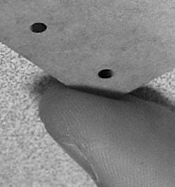
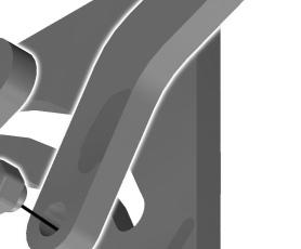
3 Complete Tuning Guide: B4 Front Suspension Ride Height, front Front ride height distance from the ground to the bottom of the chassis, with the kit fully equipped (fig. 1). To set the standard front ride height, lift up the entire car about six to eight inches off the bench and drop it. When the suspension settles, the front edge of the a-arms should be level, fig. 2. If they are not in a straight line, then add or subtract preload spacers to the front shocks, fig. 3, or adjust the threaded shock collar up or down until it is level. If you move the batteries forward or back, then recheck the ride height and adjust so it is level Associated Electrics, Inc. All Rights Reserved. CONTENTS fig. 1 Ride height distance. When should I change the ride height? You should always check the ride height after making all your other adjustments, just before you are ready to race. You should maintain your ride height level as described above, a position called arms level. Making large ride height adjustments up or down from this setting will tend to make the car feel unpredictable. If you want more steering, drop your front ride height (arms aiming downward toward the chassis). Raising your ride height will give you more push and less steering. Front ride height will also affect jumping. If your car is jumping nose-down, try raising the front end to give it more lift off the jump. fig. 2 Standard front ride height is a-arms level. This means that your a-arm edges should be in a straight line, as shown. How do I change the ride height? By adding or subtracting preload spacers to the front shocks (fig. 3), or adjusting the treaded collar up or down on the Factory Team threaded shock bodies. On setup sheet You mark here if your front ride height is level ( arms level ), or otherwise ( arms below level ). fig. 3 Add preload spacers to raise your chassis ride height. 8

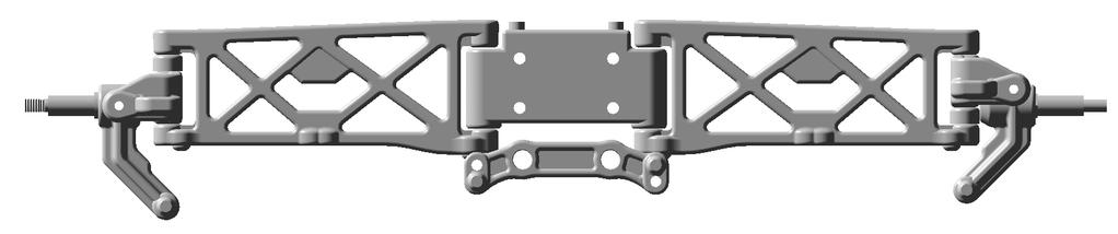
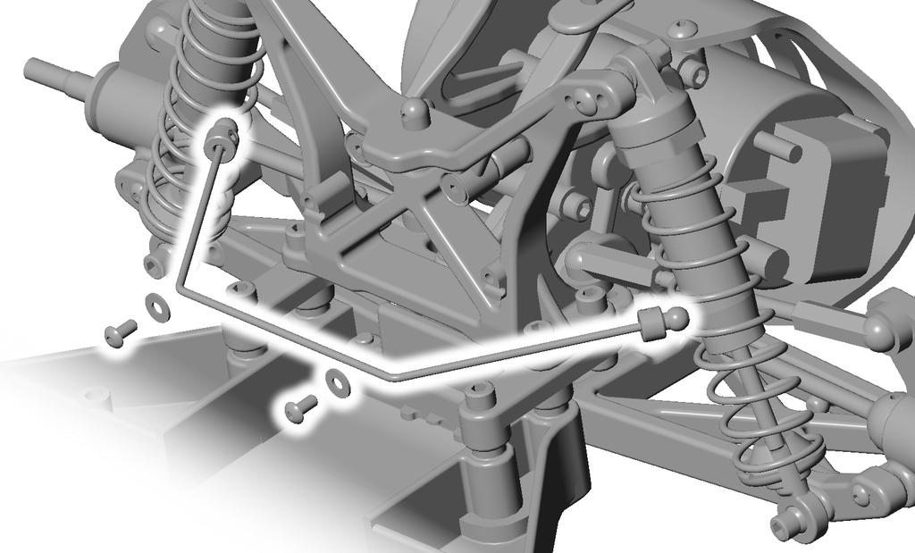
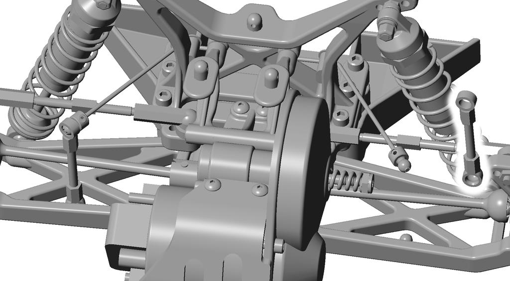
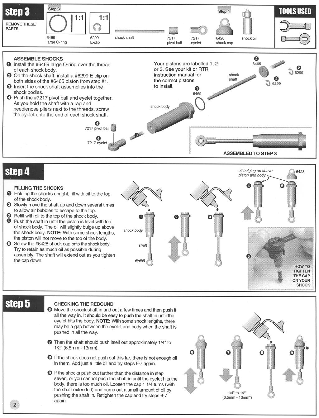
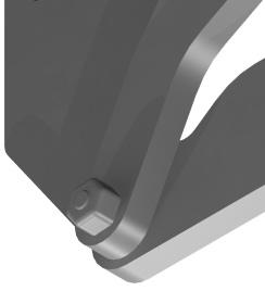
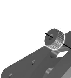
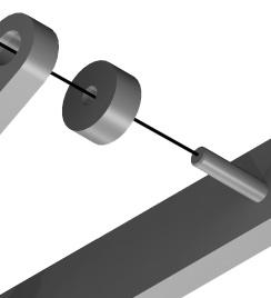
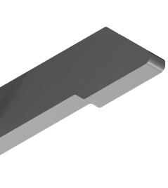
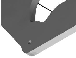
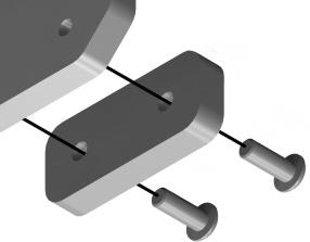
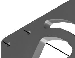
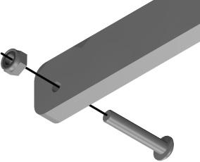
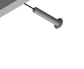
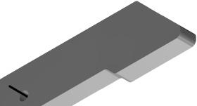
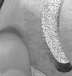
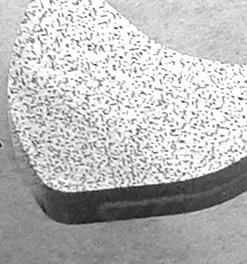
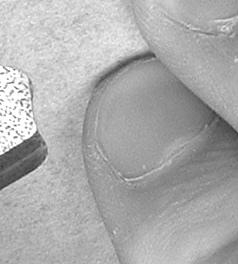
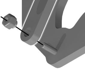
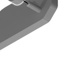
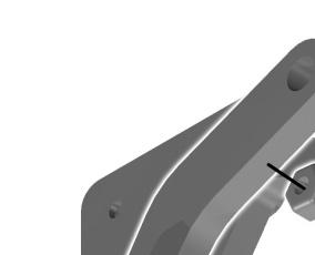
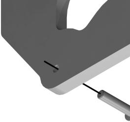
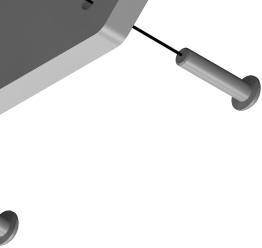
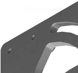
4 Complete Tuning Guide: B4 Shocks Shock Mounting, front You have three mounting positions for your shocks on the tower, and two on the front arm. When do I change the mounting position? The kit springs and inside arm hole will work best in most cases. Changing to the outer hole in the front arm will tend to make the car more stable and less responsive. Making this change requires that you remove the travel limiters from the front shocks. You should also change to a softer spring to account for the difference in leverage on the shock. Moving the front shock out on the tower (fig. 2) will decrease steering entering corners. It will also let the front end lift more off jumps. Moving the front shock in on the tower (called laying it down) will increase initial steering and give less lift off of jumps. Make sure you re-check the ride height after shock mounting changes Associated Electrics, Inc. All Rights Reserved. CONTENTS How do I change the mounting position? Remove the screw on the arm and move it to another hole. Remove the nut, washers and screw from the tower and reposition it in another hole. On setup sheet You mark here which arm hole and shock tower hole you mounted your shock. You have three choices for the tower, inside, middle and outside, and two choices for the arm. fig. 1 You have three mounting positions for your shocks on the tower, and two on the front arm O fig. 2 Mounting position 3-I shown O fig. 3 Mounting position 1-O shown. 24 TIP Sometimes if going to a heavier spring takes away too much front grip, try moving the shocks in a hole on the tower to regain a bit of steering.
5
6
7
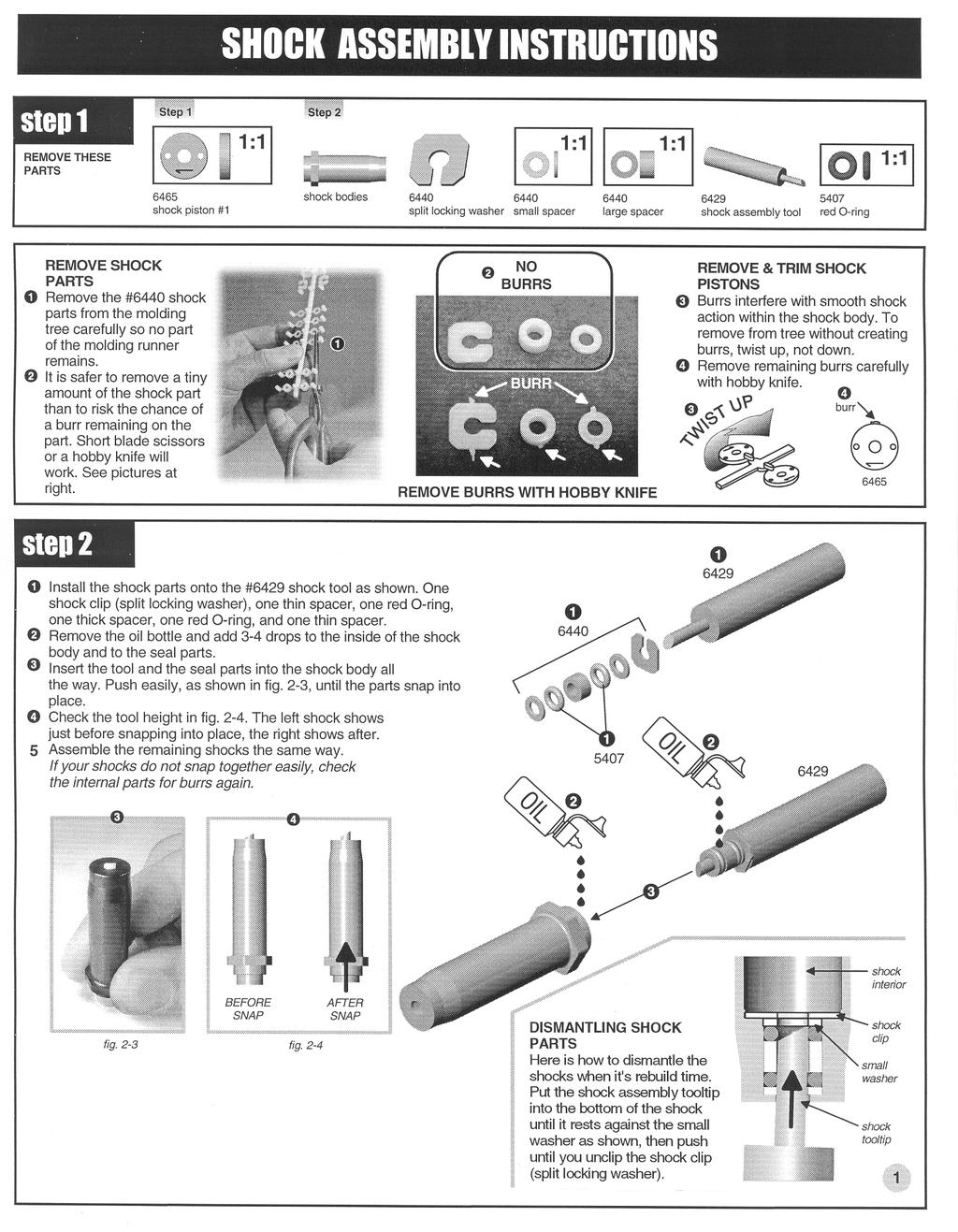
8 PART NO The shock pistons supplied are numbered #1, #2 and #3 so you can match them accurately to the shocks used on your kit according to the following tips: The #1 piston is the lightest damping and the #3 piston is the heaviest. Below are some starting points for the RC10L/10LSS, RC10c.e. & Team Car, and RC10T Truck: RC10L/10LSS: #1 piston with Assoc. 20wt silicone oil. RC10c.e. & Team Car, front & rear: #1 pistons with Assoc. 30wt silicone oil. RC10T Trucks, front: #3 pistons with Assoc. 30wt silicone oil. RC10T Trucks, rear: #2 pistons with Assoc. 30wt silicone oil. (The #1 piston is also sold separately as #6464.) Burrs interfere with smooth shock action within the shock body. To remove from tree without creating burrs, TWIST U, not down: right wrong Remove any remaining burrs carefully with a sharp hobby knife.
9 cut-away view of shock body 6440 TRIM SHOCK WASHERS & SPACERS For best shock performance, trim each part from the parts tree so no part of the two molding runners remain. It is safer to remove a tiny amount of the part than to risk the chance of a burr remaining. Short blade scissors or a hobby knife will work fine, as shown at right. Run your finger over the edges to feel for burrs you cannot see. Remove the ones you find. Burrs can keep the parts from snapping in correctly, and can cause the shock to leak or the shaft to jam. DISMANTLING THE SHOCKS WHEN IT'S REBUILD TIME Put the shock assembly tooltip into the bottom of the shock until it rests against the small washer, as shown, then push. small washer bottom of shock body shock assembly tool Install the #5407 and #6440 parts shown onto the #6429 tool tip. Add 3-4 drops of #5428 oil to the inside of the shock body, and to the shock seal parts Insert the tool tip into the shock body all the way. Push until the parts snap into place Check out Team Associated's latest Silicone Shock Oils. All bottles are 2 ounces each, $3.50. Check the tool height in photo. The right shock shows just before snapping parts in place, the left shows after. If your shocks do not snap together easily, check the parts for burrs again as in Step 2. Assemble the other shock bodies the same way. after snap before snap # wt # wt # wt # wt # wt # wt # wt # wt # wt # wt # wt TEAM ASSOCIATED web site:

10 Complete Tuning Guide: B4 Shocks Shock Springs The spring s purpose is to keep the vehicle level (fig. 1). The shock spring controls the stiffness of the suspension. This affects how the car corners and how it lifts off of jumps. Several spring tensions are available to moderate these factors. How do I know which spring to use? As a rule of thumb, running a stiffer spring on one end of the car will give that end of the car less traction, and make that end lift higher off of jumps. For example, if your car is jumping with a nose-down attitude and it has too much steering, try running a heavier front spring. For the inside hole on the front arm, the green, silver, or blue springs tend to work best. For the outside hole in the front arm, the brown or black springs tend to work better because the shock has more leverage on the arm. The Team typically runs silver rear springs in most cases. For more rear grip on slick tracks, try green (softer). For less rear grip, try gray rear springs (firmer). Stiffer springs help your suspension respond more quickly, but, because of their stiffness, they will not absorb smaller bumps as well. Softer springs are best for tracks with many small bumps. On setup sheet Write in the color of the shock springs you used. Each shock spring is color-coded according to the stiffness of the spring 2003 Associated Electrics, Inc. All Rights Reserved. CONTENTS fig. 1 Your shock springs help your buggy level off after the bumps. TIP Your shock springs are color-coded according to their stiffness. REAR 6481 Black 1.74 lb Green 1.90 lb Silver 2.10 lb Gray 2.33 lb Blue 2.55 lb Gold 2.75 lb Red 3.03 lb. softer firmer FRONT 6493 Brown 2.80 lb Black 3.20 lb Green 3.50 lb Silver 3.85 lb Blue 4.20 lb. softer firmer 22


11 Complete Tuning Guide: B4 Electrical Motor Brushes Type of motor brushes, fig. 1. The motor brush contacting the armature completes the electric circuit of your motor, therefore, the better the connection, the better the motor performance. Make sure you match your brush to the proper application. There are motor brushes designed specifically for on road or off road applications brushes that fit large commutators and others for small commutators. Serrated brushes help seat the brushes to the armature more quickly, getting you up to performance more quickly. Silver content brushes transfer power more efficiently, but wear your armature more quickly. Remove the brushes from the holders every 3 to 5 runs and inspect them for wear and burning. Clean the comm with a Comm Stick. Replace the brushes if you notice wear or burning. Failure to do this will harm your armature. If replacing brushes, it s best to true or cut the comm so there is a fresh surface for the brush to run on. See below for more on cutting the comm. On setup sheet You note which brushes you used Associated Electrics, Inc. All Rights Reserved. CONTENTS fig. 1 Motor brushes must be matched to the correct type of armature. For best performance, replace your brushes when worn. Cutting the commutator Cutting the commutator (at arrow in fig. 2) is accomplished with a comm lathe. The commutator is the area in contact with the brushes. Fine scratches form on the comm when the commutator rotates past the brushes, producing less than optimal connection. A comm lathe will trim this area so it is smooth again for optimum performance. fig. 2 The arrow points to the commutator portion of the armature. 34
 and modified (fig. 2) varieties, giving you many tuning options. How do I know which motor to use? Use the following over-simplified tips.")

, or top end speed (the highest speed attainable by that motor).")
12 Complete Tuning Guide: B4 Electrical Motor The ESC feeds your radio transmitter commands to the motor, then the motor turns the transmission gears, which then turns the axles that drive your rear wheels. Motors come in many stock (fig. 1) and modified (fig. 2) varieties, giving you many tuning options. How do I know which motor to use? Use the following over-simplified tips. Match your motor to the correct application. Off road and on road vehicles require different motors. Generally, on road racing favors more rpm while off road favors higher torque. Reedy s Kr motor, fig. 2, was designed for modified racing. Our Reedy catalog takes the guesswork out of which motor you should buy. It s free for the asking. Choose the number of turns. Turns refers to the number of times the wire was wound around each armature arm. The fewer the turns, the higher the rpm (revolutions per minute), or top end speed (the highest speed attainable by that motor). So, if you wish the fastest motor, choose a motor with the fewest number of turns. Keep in mind that the fewer the turns, the greater the battery draw, which means lesser run time. Then choose the type of wind, fig. 3. Winds of Single, Double, Triple or Quad refers to the number of strands of wire wound around the armature, double being two strands, triple being three, quad being four, and quint being five. The type of wind is for fine tuning your motor s power band. In general, the winds with fewer wires give the impression of quicker acceleration, while the winds with more wires will bring you up to top end speed more smoothly. If you have a very slick track, then winds like single and double may cause your wheels to spin; other winds triple, quad, quint may give your car better traction. In addition, the less turns of wire, the less run time you will have, because the fewer wires will draw more power from your batteries. The performance gains by changing the type of wind is subjective and may be noticed only by experienced racers with buggies that respond well. On setup sheet You write here which brand and type of motor you used. If you used a Reedy Kr 12 turn double wind, it can be written as "Kr 12x2." Associated Electrics, Inc. All Rights Reserved. CONTENTS fig. 1 Stock class requires a stock motor, such as Reedy s MVP motor. fig. 2 Modified class allows modified motors, such as Reedy s Kr modified motor. fig. 3 Arrow points to two wires, indicating that this is a Double wind. Motor Differences A modified motor is unlimited turns, adjustable timing, and includes ball bearings. A stock motor has 27 turns of a single wire, has fixed 24 degrees of timing, and bushings. Extra performance motor tips: Spray the motor commutator area with motor cleaner after every 2 to 3 runs while it is running. Over a 15 second span, spray the commutator several times for 2 to 3 seconds. Keep doing so until the runoff is clean. After the motor spray, apply a small amount of lightweight oil to each bushing for lubricating. Applying too much oil will pick up dirt and contaminate the commutator and brushes. Never overgear your motor (large pinion and/or small spur). Excess heat from overgearing can harm your motor.
.")
13 Complete Tuning Guide: B4 Electrical Motor Springs Type of motor springs, fig. 1. You can change the tension of the spring by changing the angle of its two ends (by squeezing them closer together or pushing them farther apart). The tension of the spring affects the pressure of the brush against the armature. In general, the more tension, the more torque; the less tension, the more rpm. On setup sheet You note which springs you used Associated Electrics, Inc. All Rights Reserved. CONTENTS fig. 1 Motor springs. When the two ends are in a straight line rather than angled, tension is greater. Other performance enhancements: Motor timing is accomplished by loosening (but not removing) the two top screws of the endbell (not the brush hood screws) and turning the endbell slightly. Then the screws are tightened again. Turning the endbell to the right on Reedy motors gives you more rpm and less torque, to the left results in less rpm and more torque. The timing has already been set optimally by the factory, so carefully mark a tick mark on the can aligned to a tick mark on the endbell, fig. 2, (arrow points to one such tick mark) so you can later return it to its original position. Reedy strongly recommends you keep the factory setting. Do not turn your endbell to the left beyond the timing point on the can. Explanatory note: There is usually a dent or stamp mark on motor cans to indicate the zero timing point. When the first notch on the endbell (the notch nearest the clamping screw) is aligned with the zero mark on the can, this is called zero timing. Zero timing means that the motor brushes are sitting directly in the center of the magnets. fig. 2 Note the tick mark alignment before you change your timing. 35
14 Final Drive Ratios for T4 and B4 Spur Gears Transmission Ratio of B4 and T4: 2.6:1 Equation: (Spur divided by Pinion) times 2.6 Pinion Teeth Final Drive Ratio for 72 Spur Final Drive Ratio for 75 Spur Team Associated Champions by Design


15
ASSOCIATED 1:10 SCALE ELECTRIC BUGGY INSTRUCTION MANUAL FOR THE TEAM ASSOCIATED RC10B Associated Electrics, Inc. RS-1
 ASSOCIATED 1:10 SCALE ELECTRIC BUGGY INSTRUCTION MANUAL FOR THE TEAM ASSOCIATED RC10B4 TT RS-1 2003-2006 Associated Electrics, Inc. FINAL ADJUSTMENTS RADIO ADJUSTMENTS Use the following
TIPS TO FINAL ASSEMBLY Radio installation. The Electronic speed control (ESC) and the receiver need to be mounted onto the chassis, using double sided
 and the receiver need to be mounted onto the chassis, using double sided") TIPS TO FINAL ASSEMBLY Radio installation. The Electronic speed control (ESC) and the receiver need to be mounted onto the chassis, using double sided tape (not supplied.) Mount the ESC first on the chassis
TIPS TO FINAL ASSEMBLY Radio installation. The Electronic speed control (ESC) and the receiver need to be mounted onto the chassis, using double sided tape (not supplied.) Mount the ESC first on the chassis
ROLL CENTER You can adjust the front and rear roll centers of the XB8 by changing the mounting locations of various components.
 Your XRAY XB8 luxury nitro buggy is a top competition, precision racing machine that features multiple adjustments that allow you to set up for any track condition. The XB8 includes innovative set-up features
.050 Allen key 1.5mm Allen key 1/16 Allen key 5/64 Allen key 3/32 Allen key Turnbuckle & 3/16 wrench
 1 Thank you for purchasing the Outlaw 4 Sprint Car! The Outlaw sprint car platform has been developed for loose dirt buggy tire racing. In this kit you will find the 4 th evolution of the car which features
Bag 1. Bag 1. Center Pivot. Center Pivot
 8 00734 01901 5 Center Pivot Bag 1 3374 - Center Pivot Socket 4019 - Alum Pivot ball 3254-2-56 Button Head *Note - Sometimes it is helpful to slightly over-tighten the top clamp screws, then work the ball
#0980 Intimidator 7 Direct Drive Racing Kit
 #0980 Intimidator 7 Direct Drive Racing Kit 1 Thank you for purchasing the Intimidator 7! Within this kit you will find a race winning car with over 30 years of Custom Works design and quality. The latest
A7741 Truggy Wheel, Yellow
 STEP H-01 Tire Mounting BAG H 1 2 A7780B XTT Tire, Blue Truggy Foam Insert Only sold with Tires A7741 Truggy Wheel, Yellow STEP H-02 Tire Gluing The Tires need to be glued to the wheels. This can be done
3.0 Tuning Tips. To Shut Off the Engine: Use the included pipe plug or simply bump the flywheel with a wrench or plastic handled tool.
 TM 8IGHT 3.0 Tuning Tips Before you start making changes on your 8IGHT 3.0 Off-Road Racing buggy, you need to make a few decisions. First of all, tires, and how they are setup, have a tremendous impact
The Magazine For Slot Car Enthusiasts
 The Magazine For Slot Car Enthusiasts Building the Tomy Super G+ By Milt Surratt Tomy Super G+ slot cars have been around in the current form for about 12 years. Out of the package, the Tomy HO slot car
Make these adjustments before racing
 FINAL ADJUSTMENTS ADJUSTING CAMBER To set the camber we recommend using our supplied #1719 camber/rear toe-in gauge. When adjusting camber you need to have the car ready to run with no body. Make these
RZR 900 spring/shock installation
 RZR 900 spring/shock installation Thank you for purchasing the Shock Therapy Dual Rate Spring Kit for your RZR 900. Your item list: 2 Front upper coil springs, 2 Front lower coil springs, 2 Rear upper
ON ROAD SETUP GUIDE PART ONE
 PART ONE Ride height is adjusted by the preload of the spring collars. Winding them down will raise the ride height, while winding them up will decrease the ride height. It is important to note that adjusting
Pan Car Setup and Troubleshooting
 Pan Car Setup and Troubleshooting Problems can come up in the midst of competition. Either the car is not handling properly on the track or there are problems with equipment. Troubleshooting problems should
ASSOCIATED 1:10 SCALE T3 MANUAL
 ASSOCIATED 0 SCALE T3 MANUAL INSTRUCTION MANUAL FOR THE RC10T3 ELECTRIC TRUCKS #7003, 7009, 7010, 7013, 7038, 7048 ASSOCIATED S RC10T3 TRUCK-- READER S CHOICE OF THE YEAR TIMES! Radio Control Car Action
Maintenance Information
 45530136 Edition 1 July 2008 Electric Screwdrivers EL 24V DC Series Maintenance Information Save These Instructions WARNING Always wear eye protection when operating or performing maintenance on this tool.
RHINO SUSPENSION SYSTEM INSTALLATION INSTRUCTIONS
 PARTS INCLUDED: 2 FRONT UPPER A-ARMS 2 FRONT LOWER A-ARMS 2 UNI-BALL JOINTS 2 UNI-BALL JOINT STUDS 2 UNI-BALL JOINT CAPS 2 RETAINING RINGS 1 FRONT SHOCK ASSEM. 2 DELRON STEERING STOPS 2 SHOCK MOUNT SPACERS
OWNER'S MANUAL 2000 & ROAR National Champion
 2000 & 2001 ROAR National Champion OWNER'S MANUAL Carefully read through all instructions to familiarize yourself with the parts, construction techniques, and tuning tips outlined in this manual. Being
Contents. # HUDY Caster Clip Remover Tool. # HUDY Chassis Balancing Tool. # HUDY 3mm Turnbuckle Tool
 Contents Introduction 2 Radio Adjustments 3 Speed Control (ESC) Adjustments 3 Connecting the Motor 3 Motor Gearing 3 Rollout 5 Differential Adjustment 5 Tightening the Differentials 6 Loosening the Differentials
Assembly Manual. 1/10th World GT car
 Assembly Manual 1/10th World GT car Center Pivot Bag 1 3374 - Center Pivot Socket 40194 - Hard Anodized Alum Pivot ball 3254-2-56 Button Head *Note - Sometimes it is helpful to slightly over-tighten the
RC Cheat Sheets. Set Up Your Radio-Control Car to Win! Page 1
 RC Cheat Sheets Set Up Your Radio-Control Car to Win! Page 1 Index GENERAL Page No: Ackermann 5 Anti-dive (on road) 6 Anti-roll Bars, Sway Bars 7 Anti-squat, off road 8 Anti-squat, on road 9 Axle Height,
TOO TECH RACING SET-UP INSTRUCTIONS (For Non Twin Chamber Showa & KYB)
") TOO TECH RACING SET-UP INSTRUCTIONS (For Non Twin Chamber Showa & KYB) STEP 1: Measure suspension "Race Sag". (Most important adjustment there is) First: Put the bike on a center stand and release the
TOO TECH RACING SET-UP INSTRUCTIONS (For Non Twin Chamber Showa & KYB) STEP 1: Measure suspension "Race Sag". (Most important adjustment there is) First: Put the bike on a center stand and release the
SETUP STUFF. *** (1) What is the difference between 1-B with 3 washers and 1-C with no washers?
 What is the difference between 1-B with 3 washers and 1-C with no washers?") SETUP STUFF Moving the Steering Spindle Up and Down changes two things: It changes the Total down travel your front end has. More Down travel in the front will give you more predictable landing off of
SETUP STUFF Moving the Steering Spindle Up and Down changes two things: It changes the Total down travel your front end has. More Down travel in the front will give you more predictable landing off of
Maintenance Information
 Form 16575334 Edition 1 April 2005 Electric Screwdrivers EL, EP and ET 34V DC Series Maintenance Information Save These Instructions WARNING Maintenance procedures have the potential for severe shock hazard
OTK CHASSIS- SET UP GUIDE
 OTK CHASSIS- SET UP GUIDE Introduction This setup guide is created to facilitate a user of OTK equipment to reach an optimal chassis setup and on-track performance. The different tuning possibilities and
Owners manual. Öhlins Superbike front fork FG 170
 Owners manual Öhlins Superbike front fork FG 0 Including: Setting up your fork Changing springs and seals Service the fork Trouble shooting Technical info Spare parts & tools Öhlins super bike front fork
FLOAT 3 EVOL RC2 FACTORY SERIES OWNERS MANUAL
 FLOAT 3 EVOL RC2 FACTORY SERIES OWNERS MANUAL Contents CONGRATULATIONS... 3 CONSUMER SAFETY... 3 UNDERSTANDING THE FLOAT 3 EVOL RC2... 4 FOX PUMP... 5 OPTIONS... 5 ADJUSTABLE PROGRESSIVE DUAL-STAGE AIR
Cane Creek Double Barrel Instructions
 Cane Creek Double Barrel Instructions Congratulations on your purchase of the Cane Creek Double Barrel rear shock. Developed in partnership with Öhlins Racing, the Double Barrel brings revolutionary suspension
CorkSport ort Mazda 3 Adjustable Shifter Mazdaspeed 3, Mazda 3 6-speed and Mazda3 SkyActiv 6-speed
 Part # Axl-6-963 CorkSport ort Mazda 3 Adjustable Shifter 2010-2013 Mazdaspeed 3, 2010-2013 Mazda 3 6-speed and 2012-2013 Mazda3 SkyActiv 6-speed Pre-Installation Notes: The CorkSport Adjustable Short
:: Additional Features Your new TC6 comes unassembled and requires the following items for completion. (refer to catalog section for suggestions):
:") 8/10 2 :: Introduction Thank you for purchasing this Team Associated product. This assembly manual contains instructions and tips for building and maintaining your new RC10TC6. Please take a moment to
8/10 2 :: Introduction Thank you for purchasing this Team Associated product. This assembly manual contains instructions and tips for building and maintaining your new RC10TC6. Please take a moment to
!" # 0*.!0&!&1* &23# 0
 !" # $%&'( )("*"+,'+ -.%%,$$' /.%%,+% 0*.!0&!&1* &23# 0 &*&.3# 0 INTRODUCTION Dear Customer Congratulations and thank you for purchasing a Powermover by Ultra-Fab. It is our intent to provide you with
COMPLETE TUNING GUIDE: NTC3
 COMPLETE TUNING GUIDE: NTC3 Contents Click on the button above to thoroughly familiarize yourself with the Guide. Good luck with your racing! #2382 e-book More than 50 pages, with over 70 black and white
TOOLS NEEDED TO BUILD THIS KIT
 TOOLS TOOLS NEEDED TO BUILD THIS KIT 1. ALLEN WRENCHES A..050" B. 1/16" C. 5/64" D. 3/32" E. 2.5mm 2. NUT DRIVERS A. 3/16" B. 1/4" C. 11/32" 3. MISC. TOOLS A. NEEDLE NOSE PLIERS B. THREAD LOCKING COMPOUND
DC MOTOR MAINTENANCE ALL ELECTRIC LIFT TRUCKS PART NO SRM 294
 DC MOTOR MAINTENANCE ALL ELECTRIC LIFT TRUCKS PART NO. 897076 620 SRM 294 SAFETY PRECAUTIONS MAINTENANCE AND REPAIR When lifting parts or assemblies, make sure all slings, chains, or cables are correctly
$1.00 FOR THE TQIO/RCIO
 $1.00 FOR THE TQIO/RCIO m mm HDBBYSHOP Champion Jay Halsey has an impressive track record. One of Jay's advantages is a whisper smooth tranny thanks to his dad, Jim. Now you can build a Halsey transmission!
2005 to 2008 #08 Metric Nova Chassis Set Up Sheet
 Springs 1 2005 to 2008 #08 Metric Nova Chassis Set Up Sheet Flat end of spring down on tubular lower a-arms. Left Front 800lb. Right Front 750lb. Left Rear 200lb. Right Rear 225lb. On Top of Tube Axle
ABC HOBBY ORIGINAL RADIO CONTROL CAR
 ABC HOBBY ORIGINAL RADIO CONTROL CAR Instruction Manual Study the instructions thoroughly before assembly. FRONT WHEEL DRIVE NEW STYLE STRUT SUSPENSION BATHTUB CHASSIS 4 BEVEL GEAR DIFFERENTIAL FULL ADJUSTABLE
Welcome and enjoy tuning your Manitou ABS+ Compression Damping System! Purposefully engineered to raise your expectations.
 Welcome and enjoy tuning your Manitou ABS+ Compression Damping System! Purposefully engineered to raise your expectations. PLEASE READ SERVICE INSTRUCTIONS PRIOR TO BEGINNING WORK. While revalving your
Spring manual V3.1 ENGLISH
 Spring manual V3.1 ENGLISH HYPERPRO TOOLS, used in this manual: Tool Description Part no. A, B, C Cartridge fork spring removal tool kit HP-T01 D Big Piston Fork end cap socket 45mm HP-T102 E Big Piston
Assembly Manual. 1/10th Formula 1 Car
 Assembly Manual 1/10th Formula 1 Car Center Pivot Bag 1 3374 - Center Pivot Socket 40194 - Hard Anodized Alum Pivot ball 3254-2-56 *Note - Sometimes it is helpful to slightly over-tighten the top clamp
for the B3 Sport kit #9013
 All kit versions include: 2.40:1 transmission for effortless power handling. Molded composite chassis for better rigidity and Lexan B3 racing body. Quadra-symmetric suspension for greater stability and
DRIVE AXLE Volvo 960 DESCRIPTION & OPERATION AXLE IDENTIFICATION DRIVE AXLES Volvo Differentials & Axle Shafts
 DRIVE AXLE 1994 Volvo 960 1994 DRIVE AXLES Volvo Differentials & Axle Shafts 960 DESCRIPTION & OPERATION All 960 station wagon models use type 1041 rear axle assembly. All 960 4-door models use type 1045
RZR XP 1000 Turbo Full Spring Kit
 RZR XP 1000 Turbo Full Spring Kit Polaris RZR XP 1000 Turbo 2016+ Part #: 5301154, 5301164, 5301174, 5301184, 5301194 Rev. 062018 491 W. Garfield Ave., Coldwater, MI 49036. Phone: 517-278-7768 E-mail:
INSTALLATION INSTRUCTIONS FOR THE MOTOR TRIKE CROSS COUNTRY / CROSS ROADS / HARD BALL RAKE KIT
 INSTALLATION INSTRUCTIONS FOR THE MOTOR TRIKE CROSS COUNTRY / CROSS ROADS / HARD BALL RAKE KIT Thank you for choosing the Motor Trike Cross Country / Cross Roads / Hard Ball rake kit. We ask that you read
FLOAT 3 EVOL, R, RC, RC2 FACTORY SERIES AFTERMARKET SHOCK OWNER S MANUAL
 FLOAT 3 EVOL, R, RC, RC2 FACTORY SERIES OWNERS MANUAL 2.5 PODIUM-X AFTERMARKET SHOCK OWNER S MANUAL CONTENTS CONGRATULATIONS... 3 CONSUMER SAFETY... 3 UNDERSTANDING THE FLOAT 3 EVOL SERIES... 4 FOX PUMP...
FIRST, A WORD ABOUT THE NEW RC12LC
 FIRST, A WORD ABOUT THE NEW RC12LC CONGRATULATIONS!! You have purchased the production version of the car that Masami Hirosaka used to win the 1996/97 IFMAR 1/12 scale On Road World Championships. This
EZRyde Rear Suspension Adjustment and Tuning Manual
 EZRyde Rear Suspension Adjustment and Tuning Manual Track Tension 1. Support the rear of the snowmobile with a track stand or equivalent sturdy stand. 2. Hook a spring scale around a track clip at mid-span:
Mitre Band Saw. Installation and Operating Instructions Note: Not all saw parts are shown in this booklet. Replaceable Aluminum Saw Table
 P ARTS C ATALOG 2G PARTS CATALOG Drive Wheel End Pulley Box Speed Reducer M FG. COMPANY, INC. Mitre Band Saw Installation and Operating Instructions Note: Not all saw parts are shown in this booklet Motor
!" # )("*"+,$' 0*.!0&!&1* &23# 0 &*&.444#3# 0
(*+,$' 0*.!0&!&1* &23# 0 &*&.444#3# 0") !" $%$&'( )("*"+,$' -.%%,$' /.%%,+% 0*.!0&!&1* &23 0 &*&.4443 0 INTRODUCTION Dear Customer Congratulations and thank you for purchasing a Powermover by Ultra-Fab. It is our intent to provide you with the
!" $%$&'( )("*"+,$' -.%%,$' /.%%,+% 0*.!0&!&1* &23 0 &*&.4443 0 INTRODUCTION Dear Customer Congratulations and thank you for purchasing a Powermover by Ultra-Fab. It is our intent to provide you with the
INSTRUCTION MANUAL AX90053-I001
 INSTRUCTION MANUAL AX90053-I001 2 3 AX80018 Hardware Parts Tree AX80006 Servo Set x3 AX31301 10mm Shock Caps Parts Tree (Blue) AX80069 AX31300 10mm Shock Parts Tree 2 (Blue) AX31114 WB8 Driveshaft AX80033
AFTERMARKET SHOCK FLOAT 3 EVOL R FACTORY SERIES OWNER S MANUAL
 2.5 PODIUM-X AFTERMARKET SHOCK FLOAT 3, MANUAL OWNER S FLOAT 3 EVOL R FACTORY SERIES OWNER S MANUAL CONTENTS CONGRATULATIONS... 3 CONSUMER SAFTEY... 3 UNDERSTAND THE FLOAT 3, EVOL R... 4 FOX PUMP... 5
2013 RT / 2014RT / 2015 RT - Shock Spring Adjuster Installation Instructions
 2013 RT / 2014RT / 2015 RT - Shock Spring Adjuster Installation Instructions Billet Aluminum Adjusters (2) Shock Spring Compressors (Optional) Spanner Wrench (1) BajaRon Decals Not Shown (4) Adjuster Scuff
1.1 Quad Valve and Tri-Valve. Contents WATER DUMP BODY O-RING EXHAUST VALVE QUAD VALVE TIE WRAP EXHAUST MAIN BODY O-RING
 Quad Valve and Tri-Valve Exhaust Assembly on Fiberglass Helmets Quad Valve and Tri-Valve Exhaust Contents QUAD-1 QUAD-2 QUAD-2 QUAD-2 QUAD-6 QUAD-7 1.1 Quad Valve and Tri- Valve Exhaust Assembly on Fiberglass
2011/2012 ON-ROAD AND OFF-ROAD CARS
 ON-ROAD AND OFF-ROAD CARS 2011/2012 Maverick by HPI Europe Ltd. 19 William Nadin Way, Swadlincote Derbyshire DE11 0BB United Kingdom +44 (0)1283 226570 Our catalogues, instruction leaflets, manuals, drawings,
BIG BAR SOFT SPRING SET UP SECRETS
 BIG BAR SOFT SPRING SET UP SECRETS Should you be jumping into the latest soft set up craze for late model asphalt cars? Maybe you will find more speed or maybe you won t, but either way understanding the
2. Remove front wheels.
 Read all instructions before beginning work. Following instructions in the proper sequence will ensure the best and easiest installation. Thank you for purchasing Maximum Motorsports Caster/Camber Plates.
MM Rear Coil-Over Kit - Bilstein Shocks (MMCO-3)
") 3430 Sacramento Dr., Unit D San Luis Obispo, CA 93401 Telephone: 805/544-8748 Fax: 805/544-8645 www.maximummotorsports.com MM Rear Coil-Over Kit - Bilstein Shocks (MMCO-3) Read all instructions before
3430 Sacramento Dr., Unit D San Luis Obispo, CA 93401 Telephone: 805/544-8748 Fax: 805/544-8645 www.maximummotorsports.com MM Rear Coil-Over Kit - Bilstein Shocks (MMCO-3) Read all instructions before
After Installing an Öhlins Shock Absorber/Front Fork
 Checkpoint Öhlins After Installing an Öhlins Shock Absorber/Front Fork Note! All motorcycles are designed with a suspension geometry that includes height and fork angle. Changing components (for example
along with standard XT2 Instruction Manual and also XT2 18 Supplementary Sheet.
 Use this XT2 Dirt Conversion Supplementary Sheet along with standard XT2 Instruction Manual and also XT2 18 Supplementary Sheet. Parts included in Bag 8: 303141 SHIM 3x5x1.0MM (10) 322111 XT2 COMPOSITE
ASSEMBLY AND OPERATION MANUAL
 Length: 9.5" [240mm] Width: 7.4" [185mm] Height: 4.7" [120mm] Ground Clearance: 1.25" [32mm] Weight: 25 oz [725g] approx. running weight with battery/motor/esc Technical Support Information For technical
Quarter Midget Catalog
 Quarter Midget Catalog 317.271.7100 1698 Midwest Blvd, Indianapolis, IN 46214 www.advancedracing.net 5500 SERIES QUARTER MIDGET SHOCK The Advanced Racing Suspensions quarter midget shock continues to be
BAG F STEP F-01 STEP F-02 STEP F-03. Front and Rear Clip Installation
 q STEP F-01 BAG F Front and Rear Clip Installation The Servo Link installed in Step B-03 was set to an approximate length. The correct length will vary depending on the type of servo used, the radio settings,
WARNING! Hard anodized, PTFE-coated shocks. Hard anodized, PTFE-coated MIP CVD's.
 200 Thank you for purchasing this Team Associated product. This manual contains steps and instructions you will use to set up your gas truck. Please read this entire manual before attempting to start your
TURBODYNO **WARNING**
 TURBODYNO **WARNING** It is dangerous to work in the vicinity of a lead-acid battery since they generate explosive gases during normal battery operation, To prevent an explosion when using a lead-acid
ASSOCIATED 1:10 SCALE GT MANUAL
 ASSOCIATED 0 SCALE GT MANUAL INSTRUCTION MANUAL FOR THE RC10GT GAS TRUCKS #7060, 7061, 7067, 7068, & 7090 ASSOCIATED S RC10GT-- 3 TIMES NORRCA WORLD CUP CHAMPION! 200 Thank you for purchasing this Team
Chrysler A-Body Tubular A-Arms Installation Instructions A-ARM INSTALLATION
 1967-1976 Dodge Demon 1112 67-72 Chrysler A-Body Tubular A-Arms Installation Instructions Thank you for your purchase of this Hotchkis Performance product. Your A-Arm set was designed with the performance
BEFORE YOU START. XRAY Europe K Výstavisku 6992, Trenčín Slovakia EUROPE. XRAY USA RC America, 2030 Century Center Blvd #15 Irving, TX USA
 BEFORE YOU START The X12 is a high-quality, 1/12-pan car intended for persons aged 16 years and older with previous experience building and operating RC model racing cars. This is not a toy; it is a precision
AFTERMARKET SHOCK FLOAT 3 EVOL FACTORY SERIES OWNER S MANUAL
 2.5 PODIUM-X AFTERMARKET SHOCK FLOAT 3 EVOL RC2 OWNER S MANUAL FACTORY SERIES OWNER S MANUAL CONTENTS CONGRATULATIONS... 3 CONSUMER SAFTEY... 3 UNDERSTAND THE FLOAT 3 EVOL RC2... 4 FOX PUMP... 5 AVAILABLE
Final Assembly Instructions: Bikes with Threadless Headsets
 Final Assembly Instructions: Bikes with Threadless Headsets Thank you for buying your new bicycle from L.L.Bean. Read these instructions carefully before beginning the final assembly. Prior to shipping,
The DINO files: Ford GT40 set-up
 The DINO files: Ford GT40 set-up Start removing the body and take a look to the motor mount. Using the axle with has a reduced section in the middle, we'll improve clearance between axle and motor can,
R R11 Eccentric Hub-Alu (4) R R11 Eccentric Hub-Alu (4) NOTICE. Pulley cover direction NOTICE BAG 01 NOTICE BAG 01
 R R11 Eccentric Hub-Alu (4) NOTICE. Pulley cover direction NOTICE BAG 01 NOTICE BAG 01") BAG BAG R Spool Axle Alu RA Front Spool Pulley Set 8T (4pcs) R Diff Gears (with Axle) Trim any excess flashing from the diff gear axle at the mold injection point. (pcs) (4pcs) R Spool Outdrive (pcs) R6
BAG BAG R Spool Axle Alu RA Front Spool Pulley Set 8T (4pcs) R Diff Gears (with Axle) Trim any excess flashing from the diff gear axle at the mold injection point. (pcs) (4pcs) R Spool Outdrive (pcs) R6
Shock manual V3.1 ENGLISH
 Shock manual V3.1 ENGLISH 2 Shock manual v3.1 INDEX Page Hyperpro Shock Overview 4 Maintenance 5 Rear Shock unit, removal and installation M1 Mono shock (& Telelever front) 6 M2 Twin shock 6 M3 Link system
For exploded diagram and part number information, refer to the Spare Parts Catalog available on our website at
 For exploded diagram and part number information, refer to the Spare Parts Catalog available on our website at www.rockshox.com. Information contained in this publication is subject to change at anytime
ADJUSTING THE REBOUND DAMPING
 GP10 OWNERS MANUAL ADJUSTING THE REBOUND DAMPING The rebound damping in your shock absorber controls the extension or return of the back of the bike. - The more rebound damping you have in a damper, the
Sportwerks Raven RTR Assembly and Operation Manual
 Sportwerks Raven RTR Assembly and Operation Manual Specifications: Scale.............. 1/10 Length............. 16 in (406mm) Front Track.......... 12.75 in (324mm) Rear Track.......... 12.5 in (318mm)
OWNER'S MANUAL Magnolia Ave., Chino, CA phone: (909) fax: (909)
 fax: (909)") OWNER'S MANUAL Carefully read through all instructions to familiarize yourself with the parts, construction techniques, and tuning tips outlined in this manual. Being able to grasp the overall design of
OWNER'S MANUAL Carefully read through all instructions to familiarize yourself with the parts, construction techniques, and tuning tips outlined in this manual. Being able to grasp the overall design of
Final Assembly Instructions: Runaround Cruiser
 Final Assembly Instructions: Runaround Cruiser Thank you for buying your new bicycle from L.L.Bean. Read these instructions carefully before beginning the final assembly. Prior to shipping, our expert
./#0#. 1"&." 1994 ELECTRICAL Suzuki of America Corp. - Starters. Swift
 !"" #$%!& '()!)((*(+,*)- 1994 ELECTRICAL Suzuki of America Corp. - Starters Swift Two types of starter motors are used, conventional and reduction gear. Both types of starters consist of yoke assembly,
1204AA Ford Mustang Double Adjustable Trailing Arms
 1204AA 79-04 Ford Mustang Double Adjustable Trailing Arms Special Tools Required for this Installation - 4 post lift or alignment rack preferable - Air Chisel, Angle Finder (Digital Preferred), Dead blow
20. Install and tighten the cap screws that hold the end frame and field frame together
 4006-30 19. Fill the oil reservoir in the bearing bore of the end frame with SAE 10 engine oil. Then put the the end frame on the armature shaft. Align the marks on the end frame and field frame and push
Commander SUSPENSION SYSTEM INSTALLATION INSTRUCTIONS
 PARTS INCLUDED: 2 - FRONT UPPER A-ARMS 2 - FRONT LOWER A-ARMS 4 - COTTER PINS 2-12MM JAM NUTS 2 - TIE ROD EXTENDERS 8- FLANGED DELRON BUSHINGS 4- DELRON CASTER SPACERS 6 - GREASE FITTINGS 3 - BEARING REMOVAL
ASSEMBLY AND OPERATION MANUAL
 Weight: 1lb 14oz Length: 17.25" [435mm] Width: 8" [205mm] Height: 4.5" [115mm] Wheelbase: 10.5" [265mm] Motor: 20 Turn Photon Speed Radio: 2 channel surface frequency Technical Support Information For
Installation Instructions
 Equipment Required: Wrenches: 9/16, 3/4, 1-1/8 Drill Bits: 11/32 Torque Wrench capable of reading 260 ft-lbs. Installation Instructions IN DEALERS: Please give these instructions to your customer. Do Not
MM Rear Coil-Over Kit - Koni Single and Double Adjustable Shocks (MMCO-5)
") 3430 Sacramento Dr., Unit D San Luis Obispo, CA 93401 Telephone: 805/544-8748 Fax: 805/544-8645 www.maximummotorsports.com MM Rear Coil-Over Kit - Koni Single and Double Adjustable Shocks (MMCO-5) Read
3430 Sacramento Dr., Unit D San Luis Obispo, CA 93401 Telephone: 805/544-8748 Fax: 805/544-8645 www.maximummotorsports.com MM Rear Coil-Over Kit - Koni Single and Double Adjustable Shocks (MMCO-5) Read
FOX Racing Shox. Setup Manual MOTORCYCLE
 FOX Racing Shox Setup Manual MOTORCYCLE Introduction Thank you for choosing FOX Racing Shox for your motorcycle. In doing so, you have chosen the number one shock absorber in the industry! All FOX Racing
FORK GOLD VALVE INSTALLATION STREET / ROAD RACE 37mm BPF SFF
 1501 Pomona Rd, Corona, CA 92880 951.279.6655 racetech.com FORK GOLD VALVE INSTALLATION STREET / ROAD RACE 37mm BPF SFF FK code FMGV S3702C P Thede 2.27.15 5 pgs TOOLS REQUIRED:
CALIFORNIA TRIMMER MOWER MAINTENANCE MANUAL
 CALIFORNIA TRIMMER MOWER MAINTENANCE MANUAL 2 Table of Contents Section 1: General Information Page Handle Assembly Instructions 4 Maintenance All Models 6 Oil Change Procedures All Models 9 Height Adjustment
MM Caster/Camber Plates, (MMCC7989)
") 3430 Sacramento Dr., Unit D San Luis Obispo, CA 93401 Telephone: 805/544-8748 Fax: 805/544-8645 www.maximummotorsports.com MM Caster/Camber Plates, 1979-89 (MMCC7989) IMPORTANT: The bearing used in our
3430 Sacramento Dr., Unit D San Luis Obispo, CA 93401 Telephone: 805/544-8748 Fax: 805/544-8645 www.maximummotorsports.com MM Caster/Camber Plates, 1979-89 (MMCC7989) IMPORTANT: The bearing used in our
Front Suspension. Setup and Tuning Guide
 Front Suspension Setup and Tuning Guide GEN.00000000005623 GEN0000000000000 Rev A 2015 SRAM, 2018 SRAM, LLC LLC Table of Contents Introduction... 4 Set Sag...5 Dampers... 6 Air Springs - Solo Air, DebonAir,
FACTS ABOUT WATERPROOF RC PRODUCTS
 FACTS ABOUT WATERPROOF RC PRODUCTS When an RC vehicle has waterproof stamped on the box, what does that really mean? Most people believe that you can drive that vehicle in water without any harm coming
Please read these instructions completely before proceeding with the installation.
 Fits Multi-Leaf Steel Spring Models Only. P/N 59111 This kit is for a 2" drop Please read these instructions completely before proceeding with the installation. by MN-346 (03006) ECN3100 Nylon Nut Upper
Complete Front End Suspension Rebuild, Ñ Part 1, Tear Down
 Complete Front End Suspension Rebuild, 1955-57Ñ Part 1, Tear Down by Randy Irwin There is much more to performance than pure horsepower. Great performance comes from control and Classic Chevy InternationalÕs
2007 Losi, A Division of Horizon Hobby Inc.
 Operation Manual Thank you for choosing the Mini-Slider from Losi. This guide contains the basic instructions for operating your new Mini-Slider. While the Mini-Slider is great for first-time R/C drivers,
RJS2021 LTO SPORT OVAL RACER LESS ELECTRICS
 RJS2021 LTO SPORT OVAL RACER LESS ELECTRICS THANKS FOR BUYING THE RJ SPEED 1/10 LTO SPORT KIT FOR OVAL RACING. THE ASSEMBLY WILL NOT BE DIFFICULT IF YOU READ THE TEXT, LOOK AT THE PICTURES, AND THE EXPLODED
Z-CAR ZMXT-8 RTR RTR NITRO OFF-ROAD
 TEST DRIVE EXCLUSIVE! Z-CAR ZMXT-8 RTR RTR NITRO OFF-ROAD THIS TRUGGY BREAKS THE MOLD WORDS KEVIN HETMANSKI kevinh@airage.com PHOTOS JOSEPH ARTHUR Z-CAR, A DIVISION OF SH ENGINES, is distributed exclusively
Assembly and Operating Manual. SPECIFICATION Length inch (640mm) Wing Span inch (705mm) Flying Weight oz (330g)
 Wing Span inch (705mm) Flying Weight oz (330g)") Assembly and Operating Manual SPECIFICATION Length 25.19 inch (640mm) Wing Span 27.76 inch (705mm) Flying Weight 11.64 oz (330g) Dear customer, Assembly and Operating manual VIPER The Radio Control System
Assembly and Operating Manual SPECIFICATION Length 25.19 inch (640mm) Wing Span 27.76 inch (705mm) Flying Weight 11.64 oz (330g) Dear customer, Assembly and Operating manual VIPER The Radio Control System
TUNING SECTION. It s like Ripley s Believe It Or Not Take it for what it s worth!
 TUNING SECTION It s like Ripley s Believe It Or Not Take it for what it s worth! TRANSMISSION HEIGHT The X 6 is the first mass produced off-road buggy we know of with adjustable transmission height. This
HYDRAULICS. TX420 & & lower. Hydraulic Tandem Pump Removal. 4. Remove the LH side panel (Fig. 0388).
.") TX420 & 425 240000299 & lower 4. Remove the LH side panel (Fig. 0388). Hydraulic Tandem Pump Removal Note: Cleanliness is a key factor in a successful repair of any hydraulic system. Thoroughly clean all
TX420 & 425 240000299 & lower 4. Remove the LH side panel (Fig. 0388). Hydraulic Tandem Pump Removal Note: Cleanliness is a key factor in a successful repair of any hydraulic system. Thoroughly clean all
Subaru Front Mount Intercooler Kit STI Subaru Front Mount Intercooler Kit STI
 Subaru Front Mount Intercooler Kit STI 2008-2014 715500 Subaru Front Mount Intercooler Kit STI 2008-2014 Congratulations on your purchase of the Subaru Front Mount Intercooler Kit STI 2008-2014. The following
Bag 1. Bag 1. Center Pivot. 3 Center Pivot Cap. Center Pivot
 Battle Axe 2.0 1:10th Oval Weapon from Team CRC Assembly Manual 0 2. e Ax s tle Win s! t rd Ba s + bi C. ow CR T.Q Sn 0 20 servo and saver not included Part # 100 Calandra Racing Concepts 6785 Martin Street
TP02C. 1:10 Scale Radio Controlled Electric Powered 2WD Racing Buggy. Dimensions. Length 410mm Width 250mm Height 150mm
 TP02C 1:10 Scale Radio Controlled Electric Powered 2WD Racing Buggy Dimensions Length 410mm Width 250mm Height 150mm Transmitter Preparation Power Switch Antenna 27MHzTransmitter Crystal T 27MHz ON Extend