Contents 1. General Specifications and description of design Compressor nomenclature Compressor specification
|
|
|
- Ursula Pearson
- 5 years ago
- Views:
Transcription

1
2 Contents 1. General Specifications and description of design Compressor nomenclature Compressor specification RV series compressor construction Design features Compression process Application limits Lubricants Lubricant table Pre-cautions of changing oil Oil change Compressor lifting and installation Compressor lifting Compressor mountings Installing the compressor in a sloping position Standard outline Accessories Electrical data Electrical installation with inverter V-F diagram Grounding Protection devices of compressors Operation and maintenance Compressor start-up Operation procedures Troubleshooting Compressor check list Applications General system diagram Additional cooling Economizer application Parallel system application Oil pump application Warranty...44 Appendix: CT2000FP/FPR Inverter General introduction Installation and specifications Installation and storage Outline dimensions Standard specification Wiring diagram Wiring of main and control circuit Standard external wiring diagram Terminal arrangement Digital Operator Keyboard information Frequently used parameter Parameter table An example of parameter setting Frequently used parameter description Refrigerant piping for FPR models Troubleshooting table..73
3 1. General HANBELL RV series semi-hermetic screw compressor is developed especially for applications in air-conditioning and refrigeration. With a built-in high operating load design and external inverter, each compressor is of high efficiency and reliability in all operating conditions such as thermal storage, heat pump system & refrigeration. Each compressor has the latest and advanced 5 to 6 Patented Screw Rotor Profile designed to ensure minimum clearance and high tip speed for high capacity and efficiency in all operating conditions. Each unit is compatible with the different type of refrigerants such as R134a, R22 and R407C for various needs. Each unit is carefully manufactured and inspected by high precision THREAD SCREW ROTOR GRINDING MACHINES, CNC MACHINING CENTERS, and 3-D COORDINATE MEASURING MACHINES. Each HANBELL compressor follows the ISO 9001 certification quality system. This certification assures that each compressor is controlled under severe quality procedures and HANBELL provides good service to all customers. The new developed RV series compressors combined an α Balance Piston with separated radial and axial force bearings, liquid injection & economizer connection, PTC motor temperature thermistors, discharge temperature thermistors, motor protector, and other accessories. These new designs guarantee that the compressor has the best reliability, longest life of bearings during heavy-duty running and high operating condition. This Technical Manual contains the required information for lifting, dimensions, installation, operation, applications and basic trouble-shooting. It s strongly recommended that the contents of this manual should be referred carefully prior to lifting, installation, and commissioning of RV series compressor in order to prevent any damage or accident. Please contact HANBELL or its local distributors/agents for more information or further assistance. 2. Specifications and description of design 2.1 Compressor nomenclature RV - xxx Displacement at maximum frequency Variable frequency drive compressor 1
4 2.2 Compressor specification Model RV-260 RV-410 RV-670 Displacement m³/hr 60~ ~ ~663 Compressor Rated Speed rpm 1,750~7,150 1,750~5,950 1,750~4,750 Volume Ratio Vi 2.2, 2.6, 3.0, 3.5, 4.8 Capacity Control % 25~100% 30~100% 37.5~100% Lubrication Type Starting Pressure Differential Feed 3 Phase, 2 Pole, Variable Speed Motor Starting Motor Voltage V 380~460 Frequency Hz 30~120 30~100 30~80 Insulation Protection Class F PTC, Pt100/Pt1000 Hydrostatic Pressure Test kg/cm² 42 Weight kg Compatible External Oil Separator (Optional) Model OS65 OS80 OS100 Lubricant Charge Liter Oil Outlet W 5/8 Flare 1 PF 1 PF Oil Heater W 150/300 2
 2 Power Bolt 3 PTC, Pt100/1000 Temperature")
 7 Variable Speed Motor 8 Screw Rotor 9 Economizer")
 14 Oil Connection (Discharge) 15 Oil")
5 2.3 RV series compressor construction Ref. Service Valve (Suction) 2 Power Bolt 3 PTC, Pt100/1000 Temperature Sensor 4 Liquid Injection Connection (Motor) 5 INT69HBY Motor Protector 6 Oil Connection (Motor) 7 Variable Speed Motor 8 Screw Rotor 9 Economizer Connection 10 Bearing Housing 11 Discharge Flange 12 Suction Flange 13 Liquid Injection Connection (Chamber) 14 Oil Connection (Discharge) 15 Oil Connection (Suction) 3
6 2.4. Design features Universal Application R134a, R22, R407C, R404A and R507 applicable Three types of motor A, B and C for different refrigerants and operating conditions High-efficiency Screw Rotor Profile New precise screw rotor profile with minimum clearance and high tip speed Design according to characteristics of refrigerants Highly durable Optimal Design and Robust Structure Built-in Vi without slide valve Fewer moving parts, greater efficiency Semi-hermetic design : Direct-compressed suction gas High-efficiency motor especially for variable-speed application Long-life Bearings for High Speed Rotation Robust Angular-contact Ball Bearings in Tandem Roller Bearings with New Polyamide Cages for High-speed Rotation Compact Geometry Minimal space requirement Small machine with wide range of displacement Independent Motor Cooling Cooling motor by liquid injection controlled by motor temperature sensor pt100 or pt1000 4

7 2.5 Compression process As shown in Figure 1 below, during the rotation of the rotors, the meshing shifts from the suction side to the discharge side. The meshing rotors enclose a working space, which is continuously reduced as it moves in the axial direction. This causes a V-shaped lobe space between each male and female lobes. This lobe space is maximum at suction and sealing process. As the rotors rotate further, the new meshing at the suction side closes the V-shaped lobe space. The lobe space is then constantly reduced by continuous intermeshing of the lobes (compression process). A reduction in lobe space takes places during its movement from the suction side of the rotors towards the discharge side. The volume is steadily reduced and it is thereby compressed in the sealed condition. As soon as the peaks of the rotor teeth are free to the outlet port, compressed vapor is discharged to the high-pressure side and flows to the oil separator where the high-pressured gas is separated from lubrication oil. The size and geometry of the outlet port determine the so-called internal volume ratio (Vi) of the compressor. This ratio must have a defined relationship with operating pressure ratio to avoid losses in efficiency due to under or over compression. (C) Discharge (B) Compression (A) Suction and sealing Figure1: Compression process 5


8 2.6. Application limits 6

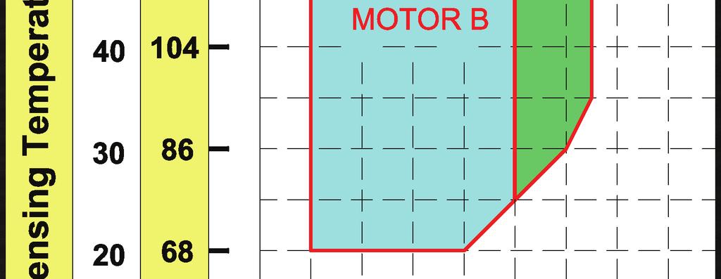


9 7
10 3. Lubricants The main functions of lubrication oil in RV series screw compressors are lubrication, internal sealing, and cooling. Bearings used in RV series compressors require a small and steady quantity of oil for lubrication. Oil injection into the compression chamber creates a film of oil for sealing in the compression housing to increase efficiency and also can dissipate part of compression heat. In order to separate oil from refrigerant gas, an external oil separator is required to ensure the least amount of oil carried into the system. When the compressor operates at low frequency, high-low pressure differential may not be significant. Hanbell suggests keep oil pressure 4kg/cm 2 higher than suction pressure or add oil pump to maintain sufficient lubrication. Please pay more attention to the oil temperature, which is crucial to compressor bearings life. Oil has a much lower viscosity at high temperatures. Too low viscosity of oil will result in poor lubrication and heat dissipation in the compressor. Viscosity is recommended to keep over 10mm 2 /s at any temperatures for oil. Oil temperature in the external oil separator should be kept above the saturated condensing temperature to prevent refrigerant migration into lubrication system. If the compressor operates under critical operating conditions, an extra oil cooler is required please refer to Hanbell selection software for the required capacity and oil flow of the extra oil cooler. High-viscosity oil is recommended to apply in high operating conditions because high discharge temperatures will make viscosity of oil lower. Oil return from the evaporator may be insufficient in such as refrigeration systems, flooded chillers etc., in which it s difficult for oil to be carried back. 3.1 Lubricant table Applicable oil types (R22) SPECIFICATION UNITS HBR -B10 HBR -A02 HBR -A04 HBR -B09 HBR -B02 HBR -B01 COLOR, ASTM 1.5 L1.0 L1.0 SPECIFIC GRAVITY VISCOSITY mm 2 /s (cst) FLASH POINT POUR POINT T.A.N Mg KOH/g COPPER STRIP 100 /3hr 1a 1a 1a MOISTURE ppm FLOC POINT DIELETRIC STRENGTH (2.5mm) kv
11 Applicable oil types (R134a, R404A, R407C) SPECIFICATION UNITS HBR -B05 HBR -B08 HBR -B09 HBR -B04 COLOR, ASTM SPECIFIC GRAVITY VISCOSITY mm 2 /s (cst) FLASH POINT POUR POINT T.A.N mg KOH/g COPPER STRIP 100 /3hr MOISTURE ppm FLOC POINT DIELETRIC STRENGTH 2.5mm kv 46.6 Note: For other applicable oil types, please consult HANBELL for further approval. 3.2 Pre-cautions of changing oil 1. Use only qualified oil and do not mix different brands of oil together. Choice of oil should match characteristics of the refrigerant used. Some types of synthetic oil is incompatible with mineral oil. Oil remained in the system should be totally cleaned up before charging different brands of oil. Charge the external oil separator with oil for the first start and then change it into new oil again to ensure that there s no mix at all. 2. When using polyester oil for chiller systems, please make sure not to expose oil to the atmosphere for prevention of change in its property. Therefore, it is necessary to vacuum the system completely when installing the compressor. 3. In order to ensure no moisture inside the system, it is suggested to clean the system by charging it with dry Nitrogen and then vacuum it repeatedly as long as possible. 4. It is a must to change oil especially if the motor has burned out because acid debris may still remain inside the system. Please follow the procedures mentioned above to change oil in the system. Check acidity of oil after 72 hours of operation and then change it again until acidity of oil becomes normal. 5. Please contact Hanbell local distributors/agents for other choices of oil to be used. 3.3 Oil change 1. Change oil periodically: Check lubrication oil every 10,000 hours of continuous running. For the first operation of the compressor, it is recommended to change the oil and clean the external oil filter 9
12 after running 2,000 hours. Check the system whether clean or not and then change oil every 20,000 hours or after 3 years continuous running while the system operates in good condition. 2. Debris in the system may block up external oil filter. To avoid this problem, it is recommended to add an oil pressure differential switch. When oil pressure differential before and after the external oil filter is over the set-point, the system should be stopped to protect compressor from oil loss. The cutout set-point is 1.5 kg/cm 2 g. 3. If the system is under an operating condition with high discharge temperature for a long time, it is recommended to check oil quality every 2 months. If the elements of oil have changed, change oil immediately. 4. Acid oil will shorten motor s life. Check acidity of oil periodically. If it is below ph 6, change oil immediately as well as the dryer filter to ensure no moisture in the system. 5. After change of the burned motor, it is necessary to check oil condition every month. Moisture and acidity of oil should be checked. 10
13 4. Compressor lifting and installation 4.1 Compressor lifting After the compressor arrives at the customer s warehouse, check whether the crate is kept in good condition and check all the compressor accessories with shipping documents to see if there is any discrepancy. Contact HANBELL or local distributors/agents immediately if there is any item damaged or missed. Cautions while lifting the compressor When lifting the compressor, it is recommended to use steel chains or steel cables as shown in Figure 2 (Case A), and also safety ropes, as shown in Figure 3 (Case B). The chains, cables or ropes must have loading capabilities, at least 2000 kgf to ensure safe lifting. Case A Figure 2: Lift the compressor with steel chains or steel ropes 11
14 Case B Figure 3: Lift the compressor with safety ropes Note: 1. Make sure that the chains, cables, ropes or other lifting equipment are properly positioned to protect compressor or its accessories, for example, angle valves, ref. service valves, terminal box, connections, etc from damaging. 2. Use only steel ropes or safety ropes to lift the compressor; don t try any ropes which are not certified for its loading capability to lift the compressor. 3. Keep the compressor in horizontal position when lifting to avoid the compressor from falling on the ground, having contact with other things because this might damage the compressor and its accessories. 4. The compressor has been charged with about 0.5 bar ( 7 psig ) Nitrogen gas inside before shipment. Release the Nitrogen gas from any service valves before installing the compressor in the chiller system. 12
15 4.2 Compressor mountings The position of the compressor in refrigeration system should be accessible and make sure the chiller base or its site is far away from any heat source to prevent heat radiation. The compressor should also be installed as close as possible to the power supply for easier connection and it s a must to keep good ventilation and low humidity condition in the site. Please make sure that the frame or support is strong enough to prevent vibration and noise when compressor is running and its clearance is enough for compressors future overhauling work. The compressor must be installed horizontally. To prevent vibration transferred from the structure and piping of the chiller during operation, cushions or anti-vibration pads (mounting pads) should be installed. The installation of anti-vibration pads is shown in Figure 4. Bolts can not be tightened until some slight deformation of rubber pads is visible. Note: It is strongly recommended the position of compressor higher than that of the evaporator. Figure 4: Compressor mountings 13
16 4.3 Installing the compressor in a sloping position Figure 5 shows a 15 limit of oblique angle for the installation of the compressor. In case the oblique angle is higher than the limit, compressor will be shut down easily. For special applications like the installation in ships, fishing boats, etc, where the oblique angle might exceed the limit, external oil separators, oil tanks and related accessories are recommended to be installed. Please contact HANBELL or local distributors for further layout recommendation. Figure 5: Limits of oblique angle for the installation of the compressor 14
17 4.4 Standard outline 15
18 4.5 Accessories (Standard), Δ(Optional) Item Description Accessibility 1 Volume Ratio Vi, 2.2, 2.6, 3.0, 3.5, Discharge Check Valve 3 Discharge Muffler 4 Suction Coupling Tube / Flange 5 Discharge Coupling Tube / Flange 6 PTC Thermistors 7 Pt100/Pt1000 Motor Temperature Sensor 8 Screw-in Discharge Temperature Sensor 9 IP-54 Terminal Box 10 Compression Chamber Liquid Injection Port 11 Motor Liquid Injection Port 12 Economizer Port 13 Discharge muffler 14 Motor protector INT69HBY 15 Discharge Stop Valve Δ 16 Suction Stop Valve Δ 17 Expansion Valve for Liquid Injection Δ 18 Solenoid Valve for Liquid Injection Δ 19 External Oil Separator Δ Note: The accessory chart is just for reference only. Actual specification and accessories enclosed might vary with different quotations and agreements respectively. If any optional accessory is required and out of the above mentioned standard accessories, please contact Hanbell for details. 16
19 a. Horizontal check valve Horizontal check valve is standard accessory for RV series compressors. Considering the limited clearance for installation and the direction of discharge port, spring-type check valve is used instead of gravity-type check valve for RV series compressors. Its dimension and installation drawing are shown as below. Diameter Dimension(mm) NO. A B Length 2 1/ A B Stop valve (Option) Discharge Flange Gasket Check valve Gasket Length Figure 6: Dimension and installation of horizontal check valve b. Discharge Muffler Discharge muffler is standard accessory for RV series compressors. It is installed between compressor discharge flange and discharge piping as sound level reducer for high pressure discharge gas. Its dimension and installation drawing are shown as below. Flange Size 2 1/2 3 4 Dimension D (mm) Dimension L (mm) Bolts Size 8 M16 55L 8 M20 55L 8 M20 55L D L Couple tube Muffler Gasket Compressor Discharge Flange Discharge Flange to OS Bolts Figure 7: Dimension and installation of discharge muffler 17
20 c. Connections Suction / Discharge Couple Tube Size 18
21 Model: RV-260 A B C D E Discharge Stop Valve 2 1/2" Discharge Check Valve 2 1/2" Suction Stop Valve 3" unit:mm 1 5/8" /4" " Copper 2 1/8" Discharge 2 1/2" Side 2 5/8" /2" Steel 2" /2" Suction Side Copper Steel 2' /8" /8" /2" /8" " /8" " /2" " Remarks : Standard Specification 19
22 Model: RV-410 A B C D E Discharge Stop Valve 3" Discharge Check Valve 3" Suction Stop Valve 4" unit:mm 2' /8" /8" Copper 2 1/2" Discharge 2 5/8" Side 3" /8" " Steel 2 1/2" " Suction Side Copper Steel 3" /8" /8" " /8" " /2" " Remarks : Standard Specification 20
23 Model: RV-670 A B C D E Discharge Stop Valve 4" Discharge Check Valve 4" Suction Stop Valve 5" unit:mm 3" /8" Copper 3 5/8" Discharge 4" Side 4 1/8" " Steel 3 1/2" " Suction Side Copper Steel 4 1/8" /8" " " Remarks : Standard Specification 21
24 d. Terminal box The compressor s electrical terminal box is fixed with its cover by 6 pieces of M8 bolts; it is adjustable in directions to meet the power cables optimal connection direction in the chiller system. Please use the spare parts which are in a bag in the crate with the compressor for your installation and keep these spare parts in the bag carefully for the future maintenance. e. PTC temperature sensor and INT69HBY motor protector In order to protect compressors, each RV series compressor has been installed three PTC temperature sensors (thermistors) inside motor coil and another one at the discharge port of the compressor. These sensors are connected to an INT69HBY protection module to monitor the motor coil temperature and the discharge temperature as well. If the temperature in one of the positions monitored exceeds the nominal response temperature of the respective PTC thermistors, the sensor resistance increases and the INT69HBY protection module output relay trips. indicates PTC sensor exceeds its response temperature Figure 8: Terminal connection diagram INT69HBY s main major functional descriptions are as follow: 1. When supply voltage is applied, the output relay pulls in after an initialization period of approx. 3 seconds, provided all thermistors lie below their rated response temperature. 22
25 2. 1 to 9 PTC thermistors with varied rated response temperatures can be connected in series to the input terminals. 3. If any thermistor resistance increases above trip level the relay drops out. This failure results in a lockout. (5 minutes delay for 1st PTC failure, 60 minutes delay for 2nd failure, lockout for 3rd failure.) 4. Lockout and time delay can be cancelled by mains reset of approx. 5 seconds. 5. A twin LED (red / green) provides operational information. 6. The relay is fed out as a N/O dry contact, which is closed under good conditions. 7. Sensor and supply circuits are galvanic isolated. Note: The motor protector phase monitor (phase loss, phase sequence) function is not suitable for variable frequency drive application. PTC Temperature Error Error Blink Codes Technical data of INT69HBY Supply voltage AC 50/60 Hz 115/120V % 3VA AC 50/60 Hz 230/240V % 3VA Ambient temperature Relay output max. AC 240V, max. 2.5A, C300 min. > 24V AC/DC, >20 ma Timer delay active (PTC < R reset) Auto reset for INT69HBY,but not for M-PI-S28 1st: 5min time delay after PTC < R reset 2nd: 60min time delay after PTC < R reset 3rd: Lockout after three consecutive PTC temp errors within 24hrs Internal error Short interruption Long interruption f. Temperature sensors Pt100 or Pt1000 The motor in RV series compressor is cooled by independent liquid injection cooling system. To effectively detect the motor coil temperature, Pt100 or Pt1000 sensor is embedded in the motor coil as a standard accessory for RV series. This temperature sensor along with the controller of the system monitors the motor coil temperature and controls on/off of the corresponding solenoid valve accordingly to provide adequate liquid injection to motor. Figure 9 illustrates the liquid injection circuit to motor. The Main S.V should be open after compressor is started as regular liquid injection to motor when compressor operates. When the motor temperature exceeds the set-point in controller, additional liquid injection is needed by opening of Sub S.V. Hanbell suggests maximum motor temperature should be under 65 in all applications. The principle to control the regulation valve after Main S.V is that: 1. The amount of liquid injection should be capable to cool motor temperature below 55 under the highest motor temperature condition: chiller s target operation condition by minimum frequency. 2. For prevention system from liquid refrigerant compression, the discharge temperature should be kept 10K over saturated condensing temperature when liquid injection to motor is practiced. When user adjusts regulation valve opening, in following above two principles, the lowest mass of liquid injection is best for higher system efficiency. If the motor temperature monitored exceeds 65 when regulation valve for Main S.V. is fully open, Sub S.V 23
26 needs be open to provide additional liquid injection to motor. The setting of Sub S.V. for its opening and closing is 65 / 55 respectively. The diameter of liquid injection circuit needs to be same with that of liquid injection connection on compressor. The combination of diameters for Main and Sub liquid injection circuit also needs to be same with liquid injection connection diameter on compressor, in design and installation. Figure 9: Installation of Liquid Injection Circuit to Motor g. Oil flow switch Oil flow switch operates with external oil separator to prevent the compressor from oil loss. Specification and installation of oil flow switch are shown as below: Type Size Process connection d1 Setpoint range(h 2 0, 20 ) Dimensions Max. flow Increasing Decreasing Nut size sw[mm] rate [l/min] I flow [l/min] flow [l/min] 1 Brass Stainless steel VHS 15M DN 15 1/2 BSP 3, 4 4,2 3,0 3, VHS 20M DN 20 3/4 BSP 7, 0 9,1 6,4 8, From compressor discharge port Figure 10: Outline drawing To compressor oil return port Figure 11: Installation of oil flow switch 24
27 h. External oil filter External oil filter is an optional accessory for external oil separator. It is suggested to install an external oil filter in oil return circuit for oil filtration before oil supply to the compressor. It s also recommended to use an oil pressure differential switch to monitor oil pressure differential before and after the external oil filter so the timing to clean or replace the oil cartridge can be noticed properly. Hanbell recommends that the trip setting of the pressure differential switch is 1.5 kg/cm 2 in order to prevent from oil loss in the compressor for its safe running. i. Liquid injection system (solenoid valve + expansion valve) Liquid injection system is an auxiliary mechanism to cool motor coil or compression chamber. In high condensing temperature or low evaporating temperature applications, liquid injection system is recommended to cool motor coil auxiliary. In high compression ratio applications, liquid injection system to compression chamber is also recommended to dissipate high compression heat due to high compression ratio to maintain a normal discharge temperature. For liquid injection to compression chamber, installation of a liquid injection expansion valve and a solenoid valve is recommended. Figure 12: Liquid injection to compression chamber 25
28 Hanbell provides following liquid injection expansion valves for customers options. Please refer to the capacity recommended in Hanbell selection software to choose appropriate liquid injection expansion valves. Installing of the remote bulb of expansion valve is very important in order to sense the pipe temperature precisely. The remote bulb should be placed on horizontal pipe, and the closer to the pipe the better. Furthermore, the remote bulb location needs to be 45 degree from the center of pipe bottom as Figure 13 shown. Brand Model Low Temp. Type High Temp. Type Y1037-FV-3-180,3/8"SAE SPORLAN Y1037-FV-5-180,3/8"SAE ALCO TCLE-3HW-6A TCLE-5HW-6A TCLE-10HW-6A FUJIKOKI JBE-E60HFKT-1 Selection of liquid injection expansion valves insulation cotton Remote bulb pipe metal ring(accessory) Remote bulb Figure 13: Installation of remote bulb of liquid injection expansion valve j. Mounting pads To avoid extra vibration and noise resulted from direct contact between compressor footings and the base on which compressor is mounted, it is recommended to add mounting pads in between. k. External oil separator To improve the oil return in applications with RV Series compressors, Hanbell specially designs external oil separators OS series with characteristics of high filtration efficiency and low pressure drop. The following table shows details of OS series for RV Series compressors: Note: It is recommended to install a buffer before the external oil separator to avoid noise and vibration caused by resonance. 26
29 ( Ⅰ ) Technical data: Oil volume (Liter) Range of application based on Shell 3 Model Type displacement ( m /hr) High level Low level (Recommended - HFC/HCFC) diameter OS50 Vertical ~ OS65 Vertical ~ OS80 Horizontal ~ OS100 Horizontal ~ ( Ⅱ ) Accessories: No. Description OS50 OS65 OS80 OS100 1 Refrigerant inlet 2 2 1/ Refrigerant outlet 2 2 1/ Oil outlet 5/8 Flare 5/8 Flare 1 PF 1 PF 4 Oil charge valve 1/4 Flare 5 High oil S.G. 1 PCS 6 Low oil S.G. 1 PCS 7 Oil level switch 1 PCS 8 Oil heater 150W 150W 150W 150W 9 Oil drain valve 1/4 Flare 10 Oil temp. protection (optional) 1/8 NPTF 11 Safety valve (optional) 1/2 1/2 1 1 (Ⅲ) Dimensions: No. OS50 OS65 OS80 OS100 A B C D E F Units: mm Vertical OS50, OS65 27
30 Horizontal l-os80 Horizontal OS100 28
31 5. Electrical data 5.1 Electrical installation with inverter RV series compressors are compatible with any general inverters (Variable Frequency Drive, VFD). The general connection diagram is as shown in Figure14. An AC reactor should be installed between the power supply and the inverter in order to prevent power system from serious breakdown. The installation of another AC reactor between the compressor and the inverter is strongly recommended, especially when the wiring length between the inverter and the motor is longer than 5m; otherwise it will probably cause serious damage to the inverter or the motor. Please discuss whether this AC reactor should be installed or not with your inverter provider. Connection of power supply of the compressor (from the inverter), Pt100/1000 and PTC sensors is as shown in Figure15. Variable Frequency Drive(VFD) Input Voltage AC Reactor Inverter AC Reactor (Optional) Motor Control Circuit 3Φ,2P,Δ Control Voltage Figure 14: The RV compressor & inverter installation diagram Figure 15: The RV motor wiring & power connection 29
32 5.2 V-F diagram The motor of RV series compressor is designed for variable speed control. Its voltage vs. frequency characteristic diagram is as shown in Figure 16. When setting the inverter by its operation manual, please choose the same V/F characteristic as shown in Figure 16 in order to operate the compressor with proper settings. Figure 16: RV motor V/F diagram Note: 1. VMAX / FMAX = Motor rated voltage / Frequency. 2. FMIN or FB could be random. Make sure that VMIN / FMIN = VC / FB = VMAX / FMAX; FMAX > FB > FMIN; VMAX > VC > VMIN. For 400V, 120Hz motor, VMAX is 400(V), and FMAX is 120(Hz) If FMIN is 0.5Hz, VMIN would be = 1.67 (V); If FB is 3Hz, VC would be = 10 (V) 3. For safety reason, the recommended way of checking V/F setting is to operate the inverter without connecting to the motor. If the ratio of output voltage and frequency is always equal to VMAX / FMAX, V/F setting is completed. 4. Once the inverter starts to drive the motor, please check the output current is normal or not in the beginning. Incorrect V/F setting would result in an excessive current. If it happens, user must shut down the inverter immediately, and recheck all the settings. 30
33 5.3 Grounding There is a grounding terminal inside the terminal box. Please accurately connect it to grounding of the control panel for the system. Earth Bolt Figure 17: Earth bolt Suggestion: a. The setting of electric leak protection should follow each country s regulation for electrical device. b. Grounding voltage of casing should be no greater than 50V; for a humid location, the limit is 25V. c. Grounding resistance should be no greater than 500 Ohm. d. If electric leak protection is active, please check if insulation of equipments is normal and if its wiring and setting are correct. Please make sure nothing wrong before turning on the power. If there are any questions, please contact the supplier of equipments. 31
34 5.4 Protection devices of compressors The table below shows a list of protection devices which are essential to safe operation of the compressor. Please follow suggestion in this table to ensure the compressor will operate in normal condition. Protection switch Set point Return point Motor wiring temperature thermistors Cutout 110 Around 100 Discharge temperature thermistor Cutout 110 Around 100 Oil-low differential pressure protector Minimum pressure differential 4 kg/cm 2 g Manual return Motor overload relay High pressure switch Low pressure switch Set with practical value, any setting should be tripped in 10 sec, According to system design According to system design Motor thermistors and discharge thermistors are temperature sensors with quick response while the temperature approach to their set point; thermistors must be connected in series to a controller (INT69HBY) in the terminal box as a guardian to protect the compressor. Alarm lamp for this protector is required to be embedded on control panel as indicator. Any intention to have short circuit in controllers for starting of compressors is prohibited. It is beyond Hanbell s warranty of compressors if there is any action above mentioned found. Note: When any protection device trips, please do troubleshooting and reset manually. Do not let the compressor reset automatically after abnormal trip! 32
35 6. Operation and maintenance 6.1 Compressor start-up PRE-START CHECKING- The table below shows the required procedures and checkpoints before starting the compressor during commissioning or initial operation of the unit. Items Things to be checked States or standard values 1. Oil level 1. Oil should be enough 2. Oil heater 2. Should be kept energized after the compressor s shutdown. 1. Accessories 3. System valves status 3. Opened 4. Solenoid valves 4. Fixed firmly. 2. Electrical system 3. Piping system 4. Safety devices 5. VFD setting 6. Compressor motor 1. Voltage of main power 2. Voltage of control circuit 3. Insulation resistance value of the motor between phase to phase and phase to ground. 4. Power terminals and wire cables terminal connection. 5. Grounded 6. Capacity of electrical accessories 7. Settings of switches, sensors and controllers. 1. Outer piping system 2. Leakage test 3. Bolts to fix the compressor. 1. Motor coil temperature sensor (thermistor) 2. Discharge temperature sensor (thermistor) 3. Controller 1. Connection with controller 2. V/F, motor rated current setting 3. Acceleration / deceleration time 1. Motor temperature (from Pt100/1000)\ 2. Liquid level (from motor sight glass) 1. Voltage of power supply should be kept within 5% tolerance to the rated voltage, instant maximum voltage drop while starting should be less than 10% tolerance to the rated voltage. 2. Standard voltage is 220V. Maximum voltage is 230V. If there is other demand, contact HANBELL. 3. Insulation resistance value should be above 5MΩ. 4. Power terminals are firmly fixed on terminal block and well insulated. Keep cables away from heat source and sharpened metal. 5. Regulated by the local electricity regulations. 6. Properly selected (or inquired by the system designer.) 7. Properly set (or inquired by the system designer.) 1. Fixed firmly. 2. No leakage. 3. Fix the compressor tightly. 1. Connected in series with discharge temperature sensor to INT69HBY. 2. Connected in series with motor temperature sensor to INT69HBY. 3. Close circuit (no reaction) 1. Those functions as speed control, malfunction feedback, VFD reset should be workable. 2. Should follow the nameplate of compressor. 3. Acceleration: 50~60 sec from 0Hz to 50Hz; deceleration: vice versa. 1. Temperature meter should be correct. 2. Lower than the upper level of sight glass. In addition to the pre-start checking given in the above table, also consider the following: a. It is necessary to pay more attention to the auxiliary facilities while the chiller is commissioning at the job-site and the periodic maintenance after the initial start-up. b. In order to keep smooth lubrication under the low ambient temperature with the normal viscosity, oil heater should be kept energized after the compressor has been shut down for preparation of the next start-up. c. Check that all the settings on each pressure switch are correct. d. Check if all the stop valves in the system are already open. e. Check the rotating direction of the compressor by starting the compressor for a transient period (approximate 0.5 or 1 sec.) and check the suction and discharge pressure gauges. When rotating in the correct direction, the suction pressure will drop immediately and the discharge pressure will go up as well. f. Oil supply to compressor should be checked immediately after compressor starting. Oil flow switch is suggested to monitor oil flow rate automatically. g. Oil foaming may occur during starting period, but it should disappear when the compressor is under stable operating conditions. Otherwise, this can indicate excessive liquid in the suction gas. h. The running condition of the compressor after commissioning should be adjusted as - the discharge temperature will be at least 10K above the saturated condensing temperature and the suction vapor superheat should be within 10K to the saturated evaporating temperature. i. The whole plant, especially the pipelines and capillary tubes must be checked for possible abnormal vibrations. Contact HANBELL or local distributors if any abnormal vibrations or noise found while the compressor is running. j. Regularly check the plant according to national regulations and the following items also should be 33
36 checked: Operating data of the machine Check the lubrication/ oil level All compressor protection devices Check electrical cable connections and tightness 6.2 Operation procedures Start the compressor: 1. For loading and unloading the compressor with the inverter, it s recommended to increase or decrease its frequency by 1 Hz at 1~2 second interval. 2. Open all solenoid valves in the system, and then start and load the compressor to 30Hz. 3. During the period of loading to 30Hz, make sure that change in high and low pressures are correct, and oil flow switch should function 5 minutes later after reaching 30Hz. 4. If there is any unusual vibration or noise from the compressor during starting, please recheck inverter settings until the situation has been improved. 5. Check whether the lubrication oil is sufficient or not through sight glasses in each oil return line. Load/unload the compressor: 1. After running in 30Hz for 5 minutes, load the compressor with another 10~20Hz increment. Thereafter, hold the frequency for 1~2 minutes before each further 10~20Hz increment. 2. After reaching full load the first time, controller can load/unload the compressor at will to meet the demand of system. 3. When changing frequency, the expansion valve should be adjusted simultaneously to meet the new flow rate. 4. Please make sure that the liquid level in the motor should not exceed the upper level of sight glass. Stop the compressor: 1. Unload the compressor to 30Hz. 2. Close all the solenoid valves for 1 minute, and then shut down the compressor. 34
37 6.3 Troubleshooting The table below shows some problems that might happen in the jobsite during commissioning or operation of the compressor. This table will only serve as a guide for engineers to understand the situation when the problem occurs in the job site. PROBLEMS PROBABILITY CAUSES REMEDY / CORRECTIVE ACTION Low suction pressure cause low refrigerant flow rate Install liquid injection to motor coil Refrigerant shortage Charge refrigerant Suction filter clogged Clean filter Sudden trip of motor High suction temperature Install liquid injection to motor coil High suction superheat Adjust the superheat less than 10K thermistor / sensor Unstable electricity system or failure Check electricity power supply Motor overload Bad motor coil causing temperature rising rapidly Bad compressor motor coil. Check the coil or change the motor stator Motor power terminal or bolt wet or frosty. Poor insulation of Motor power terminal or bolt bad or dusty. Bad insulation of magnetic contactors. Acidified internal refrigeration system. Check if the unloading SV is energized once the compressor shut down. motor Motor coil running long time continuously under high temperature. Unload the compressor before shot down. Compressor restart counts too many times. Voltage incorrect. Check the power supply Voltage drop too big when starting the compressor or magnetic contactor failure or phase Check the power supply and the contactor. failure. Motor broken down Change the motor Motor thermister sensor trip. See sudden trip of motor sensor above Compressor starting Incorrect supply power connection. Check and re-connect Discharge or suction stop valve closed. Open the stop valve failure Rotor locked Check and repair Earth fault Check and repair Protection device trip Check Damaged bearings. Change bearing. Phenomenon of liquid compression. Adjust proper suction superheat Friction between rotors or between rotor and compression chamber. Change screw rotors or/and compression chamber. Insufficient lubrication oil. Check the oil supply of the compressor is enough, add some oil if Abnormal vibration necessary. Loose internal parts. Dismantle the compressor and change the damaged parts. and noise of System harmonic vibration caused by improper piping system. Check the system piping and if possible improve it using copper pipe. External debris fallen into the compressor. compressor Dismantle the compressor and check the extent of the damage. Friction between slide valve and rotors. Dismantle the compressor and change the damaged parts. Motor rotor rotates imbalance. Check and repair. Motor line open Check Tripped overload Check the electrical connection Compressor does Screw rotors seized Replace screw rotors, bearings etc. Motor broken Change motor. not run Check for leaks. Charge additional refrigerant and adjust suction Insufficient refrigerant. superheat less than 10K Bad heat exchange in condenser Check and clean condenser Refrigerant overcharge. Reduce the refrigerant charge Air / moisture in the refrigerant system Recover and purify refrigerant and vacuum system High discharge Improper expansion valve. Check and adjust proper suction super heat Insufficient lubrication oil. Check the oil level and add oil. temperature No system additional cooling (Liquid injection or oil cooler) Install additional system cooling (liquid injection or oil cooling or both base on working condition limitation) Lack of refrigerant Check for leaks. Charge additional refrigerant. Compressor losses oil Lack of refrigerant Check for leaks. Charge additional refrigerant. Damaged bearings. Improper system piping Stop the compressor and change the bearings and other damaged parts. Check and correct the piping or install an external oil separator Improper Vi value. Liquid fills back Change the slide valve. Maintain suitable suction superheat at compressor Low suction pressure Evaporator dirty or iced Clogged liquid line filter drier Clogged suction line or compressor suction strainer Expansion valve malfunctioning Condensing temperature too low Defrost or clean coil Replace the cartridge Clean or change suction strainer Check and reset for proper superheat Check means for regulating condensing temperature Note: The replacement of compressor parts should be performed only by a qualified / certified serviceman with full knowledge of HANBELL screw compressors or HANBELL service engineers. 35
38 6.4 Compressor check list Please fill out the compressor check list and send it to Hanbell if any failure of the compressor happens. Hanbell will reply and suggest the solution to resolve the failure. CHECK LIST FOR TROUBLESHOOTING OF HANBELL SCREW COMPRESSOR Compressor model: Compressor S/N: System design condition SCT/SST: Evaporator type: Refrigerant type: Liquid injection: Chamber VFD brand name/model: VFD input voltage:r-s: S-T: R-T: VFD frequency acceleration/deceleration time: / sec VFD output current (@full load):u: V: W: VFD overload setting: A Description of problem: A:abnormal noise dba at Hz(rpm) B:abnormal vibration C:over current D:motor burnout E:leakage(Photo would be a plus) F:parts failure(photo would be a plus) G:other(Detail would be a plus) H:VFD failure(detail would be a plus) Suction Discharge pressure pressure Suction temp. Discharge temp. Liquid Condenser Chiller water Economizer Oil cooler temp. line water temp. temp. temp. temp. inlet outlet inlet outlet inlet outlet inlet outlet sales@hanbell.com & service@hanbell.com Fax: Tel:
39 7. Applications 7.1 General system diagram RV series compressor can be used with a regular air-cooled inverter or a refrigerant-cooled inverter. Please find below two typical system diagrams. System diagram 1 (with an air-cooled inverter): Note: The size of header for bearing lubricating should be greater or equal to that of oil outlet in the external oil separator. 37
40 System diagram 2 (with a refrigerant-cooled inverter): Note: The size of header for bearing lubricating should be greater or equal to that of oil outlet in the external oil separator. 38
41 7.2 Additional cooling In RV series compressor, lubrication oil has many functions such as lubricating the bearings, sealing the clearance between rotors and the compression chamber, and absorbing the compression heat. If the temperature of lubrication oil is too high, the viscosity of oil will reduce and result in poor lubrication. This will shorten the life of bearings. In strict operating conditions, for example, refrigeration, heat pump, oil cooler is necessary for cooling of lubrication oil. Hanbell selection software provides information about oil cooler capacity and oil flow rate. Oil cooler reduces the discharge temperature and at the same time gives better efficiency. Oil cooler application can be classified into 3 types: cooling by refrigerant, cooling by ambient air, cooling by cooling water. Oil cooler capacity can be calculated manually or using HANBELL selection software. When calculating manually, worst operating conditions must be considered: minimum evaporating temperature, maximum suction superheat, maximum condensing temperature and the operation mode. Oil injection application For high operating conditions with high condensing temperatures and/or low evaporating temperatures, additional cooling is required in order for the compressor to work properly. A relatively 39
42 simple method of additional cooling is direct refrigerant injection to the compressor. The purpose of installing a liquid injection system is to prevent the compressor from overheat. The system installs a liquid injection expansion valve between the liquid line and the compressor for cooling down the compression chamber. Select the high temperature expansion valve, which can sense the discharge temperature with its remote bulb. This can control the opening of expansion valve proportionally, and can reach the best cooling effect; it will control the discharge temperature at an optimal situation of around 80 C. It can also be installed with an additional solenoid valve or service valve in front of the high temperature expansion valve for the maintenance purposes. The solenoid valve will be opened while starting the compressor. The equilibrium tube of high temperature expansion valve should be connected to the high-pressure side to reflect the internal pressure. Liquid injection to chamber 40
43 7.3 Economizer application RV series screw compressor can be fitted with an additional middle-pressure connection for economizer operation within the entire range of loading. Cooling capacity as well as system efficiency can be improved by means of a sub-cooling circuit or two-stage refrigerant expansion. The pressure at the additional middle-pressure connection is at a similar level to the intermediate pressure with a two-stage system. As a result of these features, RV series screw compressor can be combined with an intermediate pressure vessel (flash tank) or an sub-cooler for two-stage expansion. These measures result in a clearly increased refrigeration capacity due to additional liquid sub-cooling, especially with high-pressure ratios. The increase in power consumption of the compressor is less than the increase in cooling capacity so better system efficiency is expected. (1) Flash Tank (2) Subcooler 41
44 7.4 Parallel system application In the rack or parallel system, it is possible that unequal-distribution of returned oil from the evaporator causing low oil level in one or more of the compressors. Install oil flow switch in each oil return line to ensure adequate oil return to each compressor. The basic design of the system is as shown below, twin-compressor parallel system connections. The accessories installed are basic and if there are more applications or protection required, please contact HANBELL or local distributor/agents for more information or further confirmation. 42
45 7.5 Oil pump application An additional oil pump is recommended to be installed in the system when the differential between oil pressure and suction pressure is less than 4bar (for example: water-cooled, flooded chiller or low frequency operation condition). If the compressor operates in the mentioned condition, insufficient oil supply to compressor will happen, which will result in poor lubrication in compressor. In addition to the installation of additional oil pump, high low pressure differential switch is also recommended to be installed in this kind of system. The min flow rate of oil supply to compressor needs to over 15L/min to ensure sufficient oil supply to compressor. Please contact Hanbell for more detailed information of oil pumps. 43
46 8. Warranty All HANBELL screw compressors are put through strict quality and performance testing prior to shipping from the factory. The screw compressors are manufactured from the finest quality material and are warranted for one year after the completion of installation and commissioning at the jobsite or up to18 months from the original date of sales by HANBELL or designated sales agent, whichever comes first. However, HANBELL will not be responsible if the compressor does not work properly for any of the following reasons: 1) damaged caused by others including shipping, natural disaster, war, etc. 2) damage caused by improper installation, operation or maintenance that is not in accordance with the HANBELL Technical Manual or instruction, 3) damaged caused by modification of any part on or connected to the compressor, and/or 4) damage caused by the improper maintenance or repair by a non-authorized technician. HANBELL will also not responsible for any accident, which may happen to personnel while installing, setting up, operating, maintaining, and/or repairing the compressor. 44
47 Appendix: CT2000FP/FPR Inverter 1. General introduction CT2000FP/FPR inverter is suitable for operating with squirrel cage induction motors. The information below is to ensure its correct and suitable application. Before installation and operation of this inverter, please consult Hanbell distributors or sales representatives for detailed information. Note : Please do not touch the circuit boards and components immediately after power is shut down. Wiring is prohibited when power is on, please do not check the components and signal on the circuit board during operation. Do not fit capacitors to the output side of the inverter in order to improve the power ratio. Run with a motor of which capacity is within the capacity of the inverter. In case of fitting MC between the inverter and the motor to control motor operation, then the capacity of inverter must be 6 times the capacity of motor. Inspection upon receiving A. Check that the model, the capacity and power voltage specifications are as ordered. B. Check that no damage has occurred during transportation. C. Check that none of the internal parts have been damaged or have fallen off. D. Check that none of the connectors have been damaged or have fallen off. E. Check that there is no loosening of the terminals or screws of each parts. If said problems occur, please contact Hanbell distributors or sales representatives. Nameplate information Example for 40HP/ V Inverter model Input spec. Output spec. Motor capacity Lot No. MODEL: CT2000FP A4 INPUT : 3Φ 440V 50//60Hz 75.9A OUTPUT: 3Φ 440V 65A 51.8kVA Motor:30kW/40HP Mass:20kg LOT NO: Weight Nomenclature of the Inverter CT2000 FP A4 CT2000 models Code A4~A9 Frame Frames for FP Code FP FPR Specification 120% load air-cooled 120% load refrigerant -cooled R1~R3 Frames for FPR Code Max. capacity of motor 030~300 30kW~300kW Code Input voltage 4 AC 380~460V 45
48 2. Installation and specifications 2.1 Installation and storage 1. Storage: If the equipment is not to be installed immediately, it should be stored in a clean and dry location with ambient temperatures from 20 to 55. The surrounding atmosphere must be free of corrosive contaminants. Power should be charged every half a year. 2. Places for installation: locations with ambient temperatures from -10 to 40, 90% relative humidity or less, and good ventilation. Avoid installing at places with dusts, iron particles, corrosive gas, water spray, direct sunlight or too much vibration. 3. Please fix the inverter under the cooling fan if it is installed in the panel. The heat dissipated from the inverter will be discharged out of the panel to reduce the temperature of inverter and for better ventilation as shown below. Discharged heat FAN Heat from the inverter 10~20 cm 10cm 10cm CT2000F At least 30 cm 46
49 2.2 Outline dimensions D FP models (unit:: mm) F A4~A5 Frame A6~A9 Frame G A B C D E F G H A Φ7 A Φ7 A Φ10 A Φ10 A Φ10 A Φ10 FPR models (unit:: mm) R1~R3 Frame G A B C D E F G H Port* R Φ7 1/4 R Φ10 1/4 R Φ10 3/8 *NPT flare 47
50 2.3 Standard specification FP / FPR models Control method V/F vector PWM control Frequency accuracy Digital setting:±0.01 Analog setting:± 0.5%(35 ) Frequency resolution Frequency range V/F ratio Digital setting:0.01 Hz 0.00 ~ Hz 14 patterns, or any V/F patterns. Analog setting:(max. frequency/1024)hz Torque boost Motor auto-tuning, automatic torque boost (1Hz torque above 150%) Acce./ Dece. time Brake Standard feature Frequency setting Display Protection 0.0 ~ sec.(linear, two-step setting) DC, dynamic brake (below 11kW) 120% overload, jogging speed, upper/lower frequency limit setting, 8-step speed setting, multi-step function, RS485/RS422 communication, jump frequency, PID control, multi-function DI & analog input interface Digital setting by keypad, analog setting by keypad(dc 0~10V), analog setting(dc 0~10V 4~20mA) LCD display, 7-segment LED display, frequency, current, voltage, setting value, function, indicators, fault status Phase loss, low voltage, over voltage, overload, over current, overheated, subthreshold current Overload capacity 120% for 1 min, anti-time limit function Altitude Ambient temperature -10 ~ 45 Vibration Below 0.5g Humidity Protection degree IP00 Indoor, altitude 1,000m or lower, Relative humidity between 45 % and 90% (no condensing) FP 400V models Motor rating (kw) Model ( CT2000FP-4) Rated current (A) Rated capacity (kva) Rated input voltage 3φ, 380~460V ±10%, 50 / 60Hz ±5% Rated output voltage 3φ, 380~460V ±10% Cooling system Forced air-cooled Outline dimensions A4 A4 A5 A5 A6 A6 A7 A7 A7 A8 A8 A9 Weight (kg)
51 FPR 400V models Motor rating (kw) Model ( CT2000FPR-4) Rated current (A) Rated capacity (kva) Rated input voltage 3φ, 380~460V ±10%, 50 / 60Hz ±5% Rated output voltage 3φ, 380~460V ±10% Cooling system Refrigerant-cooled Outline dimensions R1 R1 R1 R2 R2 R2 R2 R3 R3 - Weight (kg)
52 3. Wiring diagram 3.1 Wiring of main and control circuit Wiring the master circuit and control circuit Wire according to the standard connection diagram. When using the external sequence control, please use small signal relay or double terminal relay to avoid relay terminal malfunction. Signal wire The signal circuit, which uses either shielded pairs or twisted pairs, should be wired either using a wiring duct separated from that for the power circuit, or with the wiring conduit isolated as much as possible. Wiring between main circuit and motor Connect the main circuit, by wiring according to the main circuit terminal connection diagram. Care is required not to make a mistake when connecting the input and output terminals, lest it will cause inverter damage. Specifications of main circuit path and NFB are as follow: Voltage (V) Model NFB (A) Standard wiring (mm 2 ) CT-2000F CT-2000F CT-2000F CT-2000F ~100 CT-2000F ~100 CT-2000F ~100 CT-2000F ~100 CT-2000F CT-2000F ~200 CT-2000F ~200 CT-2000F ~200 CT-2000F *CT2000F No. P PR Specification 120% load forced air-cooled 120% load refrigerant-cooled 50
53 AC Reactor ( ACL ) The main purpose of fitting A.C.L. at the R.S.T. input side is to curb instantaneous current and to improve ratio. Fitting the A.C.L. to R.S.T. input side is a must under the following circumstance: A. Where power system capacity is over 500kVA. B. Using thyrister, phase advance capacity etc. for the same power supply. Inductance of power side from R.S.T of inverter(a.c.l) Voltage (V) Model Current value (A rms) Inductance CT-2000F A 0.26mH CT-2000F A 0.21mH CT-2000F A 0.18mH CT-2000F A 0.14mH CT-2000F A 0.11mH CT-2000F A 0.10mH CT-2000F A 70uH CT-2000F A 70uH CT-2000F A 60uH CT-2000F A 50uH CT-2000F A 40uH CT-2000F A 30uH *CT2000F No. P PR Specification 120% load forced air-cooled 120% load refrigerant-cooled 51
54 3.2 Standard external wiring diagram NFB P N R S A C R S U V IM T L T W Multi-function input(di Multi-step speed 1 Multi-step speed 2 Multi-step speed set 2 Fault reset Multi-step speed set 1 Free run stop REV FWD COM S1 S2 S3 S4 S5 S6 RR FR COM FM AM CC MA MB MC M1 M2 M3 Analog output 0~10V Max 5mA Multi-function Output terminals AC 240V Max 1A DC 28V Max 2A External frequency references P1 PC Open collector DC 48V Max 50mA 10V 2k Ω 4~20mA 2k Ω IN1 ( 4~20mA) IN2 (0~+10V) IN3 (0~+10V) CC EG TA TB RA RB IG MODBUS RS422/485 Shield wires Twisted shield wires 52
55 3.3 Terminal arrangement IU IV C16D225 (Control board 1) IW Optional card connector RS 485 / 422 Multi-function Output terminals KEYPAD Communication terminals Analog input terminals Open collector Multi-function terminals E1 M2 M1 M3 MB MA MC TA TB RA RB IG EG 10V IN1 IN2 IN3 CC FM AM CC P1 PC COM S1 S2 S3 S4 S5 S6 RR FR COM R S T E U V W N P Master circuit terminals (A3~A4, R1) Note: R1 has no terminal N and P. 53
56 IV IW C16D225 (Control board 1) Option card connector RS 485 / 422 Multi-function Output terminals KEYPAD Communication terminals Analog input terminals Open collector Multi-function terminals E1 M2 M1 M3 MB MA MC TA TB RA RB IG EG 10V IN1 IN2 IN3 CC FM AM CC P1 PC COM S1 S2 S3 S4 S5 S6 RR FR COM R S T U V W N P Master circuit terminals (A5~A9, R2~R3) E Note: R2 and R3 has no terminal N and P. 54
57 Terminal Specification Classification Terminal symbol Description Specification R.S.T AC power input terminal 3ΦAC 380~460V 50/60HZ Main Circuit Analog input/ output terminal Multi-functional analog input terminal Operation control terminal Multi-functional analog output contact MODBUS communication terminal Open-collector output common Grounding terminal U.V.W Inverter output terminal 3-phase induction motor E Ground Terminal Ground Terminal of inverter 10V +10V power output Provide +10VDC 30mA power CC Common of analog input/ output Common of analog input/ output terminal IN1 Multi-functional analog input 1 4~20mA / 0~10V input IN2 Multi-functional analog input 2-10~+10V / 0~10V input IN3 Main speed analog input 3 0~10V input FM AM Multi-functional analog output 0~10V 5mA output S1 Multi-functional analog output terminal 1 S2 Multi-functional analog output terminal 2 S3 Multi-functional analog output terminal 3 S4 Multi-functional analog output terminal 4 DC +24V 8mA Photocoupler isolation S5 Multi-functional analog output terminal 5 S6 Multi-functional analog output terminal 6 COM Concurrent of multi-functional input Contact and operation control terminal terminal COM common RR reverse / stop terminal ON: reverse, OFF: stop FR forward / stop terminal ON: forward, OFF: stop COM Operation control terminal Multi-functional input and operation control terminal common MA, M1 Multi-functional output contact A MB, M2 Multi-functional output contact B 240VAC Max 1A MC, M3 Multi-functional output contact 28VDC Max 10A concurrent TA RS422 T+ RS422 T+ or RS485 + terminal TB RS422 T - RS422 T - or RS485 - terminal RA RS422 R+ RS422 R+ RB RS422 R - RS422 R - IG Shield grounding terminal Provide shield grounding system 0V P1 PC EG Multi-functional output connector Multi-functional output connector common Shield grounding terminal Below DC 48V 50mA Offer shield grounding, applied for analog and input terminal 55
58 4. Digital Operator 4.1 Keyboard information Numeric KEYBOARD Operator panel parts names and functions 7-segement monitor 1.Displays frequency Cd02=0 Displays current Cd02=1 Displays RPM NO2=2 Displays various readings see Cd02 2. After indicates alarm, ignore Cd02, directly displays failure status READY Displays that the panel is ready to accept key input Monitor mode display Displays monitor status Ten-key pad Data input key Operation monitor display Displays forward/reverse/stop status Cutes Corporation READY HZ A ALARM Operation instruction keys FWD REV STOP Control from keyboard External control operation, stop mode by set Cd04=1 PROG PROG SET READ SET 1 0. STOP key Step keys 1.Stops inverter operation Resets function 2.Resets function 3. Resets alarm indication 3.Resets alarm indication 1. To change frequency 2. Select function items Function setting keys These three keys offer selecting read or setting value of function 56
59 All operation modes The operation modes of inverter equip monitoring and input modes. This section describes details of all modes and switch between modes. A. Setting mode selection READY HZ A ALAR Frequency is shown on the monitor after power input, READY and HZ indicator lit. Press PROG key READY 下 A Monitoring item is Cd-00 Press keys to select user s setting. Press PROG key READY HZ A ALAR Monitoring item is CE-00 Press keys to select user s setting. Press PROG key READY HZ A ALAR Back to monitoring (HZ) B. Modify monitoring item READY HZ A ALARM DISP indicator lit means monitoring item. Operation command is shown when stop operation. (HZ LED lit when display is frequency) Press PROG key READY HZ A ALARM Monitoring item is Cd-00 Press keys to select user s setting. Please use or numeric keys to change figures READY HZ A ALARM Monitoring item is Cd-02 Press keys to select monitoring item. 57
60 Press READ key READY HZ A ALARM Enter Cd-02 monitoring item. Factory value is operation frequency. Please use or numeric keys to change figures READY HZ A ALARM Enter Cd-02 monitoring item. Modify constant is load current. Press SET key READY HZ A ALARM Set constant, indicate PASS Twinkle twice (Indicate Err if set wrong) READY HZ A ALARM Back to Cd-02 Press PROG key READY HZ A ALARM Monitoring item is CE-00 Press PROG key READY HZ A ALARM Monitoring item isload current (No load is A 0.0) C. Inspect malfunction record and monitoring value Press READ key READY HZ A ALARM Monitoring item is d1-00 Press key to modify figure. Please use or numeric keys to change figures READY HZ A ALARM Monitoring item is malfunction record is d1-29. (Please refer to the monitoring chart) 58
61 Press READ key READY HZ A ALARM READY HZ A ALARM Malfunction record is noer means no record. OC means over current. D. Press FWD/ REV key under any status READY HZ A ALARM Monitoring item is (HZ). Frequency command is shown when stop run. Press FWD key FWD REV STOP READY HZ A ALARM Press FWD/REV key and enter monitoring mode, monitoring mode is set by Cd-02. (FWD/REV indicator lit) Press PROG key READY HZ A ALARM Enter input mode. Press key or numeric keys to select constant, press key to shift the cursor. Select it to modify operation frequency. Press READ key READY HZ A ALARM Enter input mode. Press key or numeric keys to select constant. Please use or numeric keys to change figures READY HZ A ALARM Enter input mode. Press key or numeric keys to select constant. Modify the frequency is 20.00HZ 59
62 Press SET key READY HZ A ALARM Set constant, indicate PASS. Twinkle twice (Indicate Err if set wrong) READY HZ A ALARM Back to Cd-00 Press PROG key READY HZ A ALARM Monitoring item is CE-00 Press PROG key READY HZ A ALARM The inverter output frequency is modified to be 20.00HZ. 60
63 5. Frequently used parameter 5.1 Parameter table Code No. Function Cd-00 Setting frequency Cd-01 Selecting frequency command Cd-04 Operation command selecting Cd-05 Set V/F pattern Cd-06 Motor rated current Cd-08 Acceleration time 1 Cd-09 Deceleration time 1 Upper limit of Cd-17 frequency Lower limit of Cd-18 frequency Cd-32 IN1 function selecting Description Input master speed frequency by keyboard ( frequency command 1) 0:Digital input by key board 1:Analog input 2:Analog input (lag) 3:Multi-step function 4:DI UP/DOMN(2) 5:Pulse input 6:Keypad UP/DOMN (1) 7:Keypad UP/DOMN (2) 0:Keyboard operation 1:External terminal (Keyboard stoppable) 2:MODBUS (Keyboard stoppable) 3:External terminal (Keyboard unstoppable) 1~14: Select from fixed 15 V/F mode. 15: Set by from Cd51to Cd58 V/F mode. Set motor rated current as inverter current is torque boost gain as ratio. The time needed for setting frequency from 0 Hz to 50 Hz The time needed for setting frequency from 50 Hz to 0 Hz Set the upper limit of frequency command Set the lower limiter of frequency command 4~20mA input mode, set IN1 function 0: De-active 1: Analog master speed (1st speed, frequency command 1) 2: Adding master speed (analog master speed auxiliary command) 3: Master speed gain 4:Auxiliary frequency 2 5: Auxiliary frequency 3 6: DC brake current 7:PID feedback value 8:PID command value Setting value 0.00~ Factory setting HZ Change during operation Modbus Address Yes 128 0~7 0 No 129 0~3 0 No 132 1~15 2 No ~ ~ ~ ~ ~ % 10.0 sec 10.0 sec Hz No 134 No 136 No 137 No 145 0Hz No 146 0~8 0 No 519 Cd-33 IN1 input bias Set percentage bias for 4mA when input ± Yes 520 Cd-35 IN3 function selecting 0~10V input mode setting, set IN3 function 0: De-active 1: Analog master speed (1 st step speed, frequency command 1) 2: Adding master speed (analog master speed auxiliary command) 3: Master speed gain 4:Auxiliary frequency ~8 0 No 519
64 5: Auxiliary frequency 3 6: DC brake current 7:PID feedback value 8:PID command value Cd-36 IN3 input bias Set percentage bias when 0V input ± Yes 520 Cd-38 IN2 function selecting 0~10V input mode setting, set IN2 function 0: De-active 1: Analog master speed ( first step speed, frequency command 1) 2: Adding master speed (Analog master speed auxiliary command) 3: Master speed gain 4:Auxiliary frequency 2 5: Auxiliary frequency 3 6: DC brake current 7: PID feedback value 8: PID command value 0~8 1 No 519 Cd-39 IN2 input bias Set percentage bias when 0V input ± Yes 520 Cd-47 Cd-48 Cd-51 Multifunction relay 1 output function selecting Multifunction relay 2 output function selecting Motor rated voltage Motor rated Cd-52 frequency Maximum Cd-53 output frequency Cd-54 Maximum voltage Cd-55 Cd-56 Cd-57 Middle output frequency Middle output voltage Minimum output frequency Cd-58 Minimum output voltage Cd-95 function Cd-96 Multifunction terminal S4 Multifunction terminal S5 function 0: Timer (act when RUN time reach to Cd29 value) 1: Malfunction 2: Stopping 3: Acceleration 4:Speed agree 5: Deceleration 6: Frequency arrive ( operation frequency > Cd45 value) 7: Current arrive (compares to Cd85and Cd86 value) 8: Overheat (Cd82) predict action 9: OL malfunction action 10: x Each factory value of each model Set V/F curve, please adhere to the following rules: Cd53 Cd52>Cd55 Cd57 Cd54 Cd51>Cd56 Cd58 0: 3-wire operation control 1: Multi-step speed 1 2: Multi-step speed 2 3: Multi-step speed 3 4: Reserved 5: JOG frequency 0~10 1 No 175 0~10 1 No ~ ~ ~ ~ ~ ~ ~ ~ By spec Hz 60.0 Hz By spec. 3.0 HZ By spec. 0.5 Hz By spec. No 527 No 528 No 529 No 530 No 531 No 532 No 533 No 534 0~21 8 No 561 0~21 1 No
65 Cd-97 Multifunction terminal S6 function Cd-98 Lock data CE-54 Select PID control CE-55 Proportional control ( P ) CE-56 Integral time ( I ) 6: Forward JOG 7: Reverse JOG 8: Auto restart attempts 9: Multi-steps acceleration time 10: Multi-steps deceleration time 11: PID control disable 12: PID integration control reset 13: PID integration control maintain 14: PID soft start 15: Switch PID error input characteristics 16: Not used 17: PLC reset 18: Emergency stop 19: Coast stop 20: Electrical adjustable speed UP 21: Electrical adjustable speed Down 0: Lock data (read only) 1: Data is variable (simple) 2: Data is variable 0: invalid 1: PID output is inverter output, D control error 2: PID output is inverter output, D control feedback 3: PID output is adjustment of inverter output, D control error 4: PID output is adjustment of inverter output, D control feedback 0~21 19 No 563 0~2 2 Yes 564 0~4 0 No 282 Set ratio gain of P control 0~ Yes 283 Set integral time of I control 0~ Yes 284 Note: The above table only lists frequently used parameters. Please contact Hanbell for more parameters. 63
66 5.2 An example of parameter setting Compressor: RV-670 Inverter: CT2000FPR R3 Motor: 3ψ2P, 400V/80Hz Capacity control: Stepless, analog input 0~10V(IN2) Code No. Cd-00 Cd-01 Cd-04 Cd-05 Cd-06 Cd-08 Cd-09 Setting value Code No. Cd-17 Cd-18 Cd-38 Cd-39 Cd-47 Cd-51 Cd-52 Setting value Code No. Cd-53 Cd-54 Cd-55 Cd-56 Cd-57 Cd-58 Cd-95 Setting value Code No. Cd-97 Cd-98 Setting value 19 1 IV IW C16D225 (Control board 1) Option card connector RS 485 / 422 Multi-function Output terminals KEYPAD Communication terminals Analog input terminals Open collector Multi-function terminals E1 M2 M1 M3 MB MA MC TA TB RA RB IG EG 10V IN1 IN2 IN3 CC FM AM CC P1 PC COM S1 S2 S3 S4 S5 S6 RR FR COM Malfunction Alarm(NO) Analog Input 0~10V VFD Reset Command Controller/PLC Start Command Controller/PLC Stop Command 64
67 5.3 Frequently used parameter description Parameter setting by function Frequency setting Code No. Function Setting value Factory setting Change during operation Cd00 Frequency setting 0~400.00HZ Description: There are 5 methods to change set frequency. Items A~C are methods of panel key operation, items D-E are methods of external terminal input. A. At display function, press READ and setting (Cd01=0) B. Use PROG key to input data (Cd01=0) C. Use key to input data (Cd01=0) D. Use Multi-Step function to setting (Refer to function CE05 to CE55.) E. Set external voltage F. Set external current Note: Set value should be in accordance with V/F slope (Cd05) and upper limit frequency (Cd17). Set by function key A. At display function, press READ and setting (Cd01=0) F PROG C d READ SET C d PROG C E PROG
68 B. Use PROG key to input data (Cd01=0) F Numeric key SET F Note: Indicate 7 Segment LED twinkle Frequency command selecting Code No. Cd01 Function Selecting frequency command Setting value Factory setting Change during operation 0~8 0 X Description: Constant Cd01 is input way selecting of frequency, selectable items as following: 0: Digital input by key board 1: Analog input 2: Analog input (lag) 3: Multi-step function 1 4: DI UP/DOMN(2) 5: Pulse input (option) 6: Keypad UP/ DOMN (1) 7: Keypad UP/ DOMN (2) 8: Set frequency by terminal VR (E2 only) Use keypad to input frequency command Input frequency command by keypad after set Cd01=0. Use constant Cd00 to input frequency commad when ordinary operation. Use voltage (current) to input frequency command (analog input IN1~IN3, option cardai1~2) Input frequency command by analog input after set Cd01=1. Input frequency command (contained lag) by analog input after set Cd01=2. Input frequency command by multi-step function to set multi-step function Set Cd01=3 to execute multi-step function. 16 steps are settable and set each step command by CE05~CE36. DI UP/ DOMN Set DI terminal to execute frequency UP/ DOMN by Cd92~Cd97 after set Cd01= 4. Set acceleration/ deceleration by Cd10. Pulse input (option card is underdevelopment) Use pulse input terminal of option card to input pulse as frequency after set Cd01=5. Keypad UP/DOMN Set frequency by UP/ DOMN of keypad after set Cd01= 6, 7. Set acceleration/ deceleration by Cd10. 66
69 Set frequency by terminal VR Set frequency by terminal VR after set Cd01=8. (E2 only) Operation command selecting Code No. Cd04 0~3 0 X setting Description: Cd04=0: keypad control : Use FWD REV STOP key of keypad to execute inverter operation. Cd04=1: External terminal control (stoppable by keypad) : Use operation control terminal to execute inverter operation. Stoppable by keypad (STOP). Cd04=2: MODBUS communication : Use MODBUS communication to execute operation. (page 74) Cd04=3: External termonal control (No keypad stop) : Use operation control terminal to execute operation. No keypad stop (STOP) Acceleration/ deceleration Code No. Function Operation command Function Setting value Setting value Description: Set frequency by the time is needed from 0 HZ to 50 HZ. Factory setting Factory setting Change during operation Change during operation Cd08 Acceleration 1 0.0~ O Cd09 Deceleration 1 0.0~ O T1:time for acceleration/ deceleration F:Frequency change For example: Frequency is reduced from 50 HZ to 30 HZ, time 1 sec Output/ input terminals Multi-functional analog input Code No. Function Setting value Factory setting Change during operation Cd32 IN1 function selecting 0~8 0 X Cd33 IN1 input bias ± % O Cd35 IN3 function selecting 0~8 0 X Cd36 IN3 input bias ± % O Cd38 IN2 function selecting 0~8 1 X Cd39 IN2 input bias ± % O 67
70 Description: Terminals of IN1 ( 4~20mA), IN2 (0~+10V) and IN3 (0~+10V) are multi-function analog input, the input specification 10V(20mA) indicates 100%, use Cd31, Cd34 and Cd37 to set enlarge/ reduce magnification, and Cd33 Cd36 Cd39 to set bias %. Cd32 Cd35 Cd38. All functions of multi-function analog input, please refer to multi-functional analog input function list. Note: Limits of authority level IN3>IN2>IN1 For example: Set Cd32(IN1) and Cd35(IN3)=1 at the same time, and IN1 will not operate when input IN3. Multi-functional analog input function list Code Function Description No. 0 De-active Analog master speed (1 st -step speed) Frequency command 1 2 Adding master speed Analog master speed auxiliary command 3 Master speed gain Analog master speed limit gain 4 5 Auxiliary frequency 2 (2 nd -step speed) Auxiliary frequency 3 (3 rd -step speed) Frequency command 2 Frequency command 3 6 DC braking current Inverter rated current 7 PID feedback value Feedback value source 8 PID command value PID input value Multi-functional relay setting Code No. Cd47 Cd48 Function Multi-functional relay 1 (MA, MB) Multi-functional relay 2 (M1, M2) Description: Set multi-functions output contactor function. Setting value Factory setting Cd47, 48 could be set the function by Multi-functional output contactor, please refer to the list: Change during operation 0~10 1 X 0~10 1 X Setting Function 0 Time counter (accommodate Cd29) 1 Fault 2 Stop 3 Acceleration 4 Speed reached 5 Deceleration Frequency reached (operation 6 frequency>cd45) Current reached (compare to Cd85 and Cd86 7 value) 8 Over heating prediction action(cd82 Cd84) 9 OL fault action 10 No action 68
71 Multi-functional terminal setting Code No. Cd95 Cd96 Cd97 Function Multi-functional terminal S4 function Multi-functional terminal S5 function Multi-functional terminal S6 function Setting value 0~21 Factory setting 8 Change during operation 0~21 1 X 0~21 19 X X Setting value Function 0 3-wire operation control 1 Multi-step speed command 1 2 Multi-step speed command 2 3 Multi-step speed command 3 4 Reserved 5 Jog frequency selection (JOG) * 6 Forward jog (FJOG) * 7 Reverse jog (RJOG) * 8 Auto restart attempts 9 Multi-step acceleration/ deceleration time 1 10 Multi-step acceleration/ deceleration time 2 11 PID control disable 12 PID integration control reset 13 PID integration control maintain 14 PID soft start 15 Switch PID error input characteristics 16 Not used 17 PLC reset 18 Emergency stop by time of Cd11 19 Coast stop 20 Electrical adjustable speed UP 21 Electrical adjustable speed Down * Only Cd04=1 69
72 5.3.3 Multi-functional terminal setting V/F free pattern setting Code No. Function Setting value Factory setting Change during operation Cd05 Set V/F pattern 1~15 15 X Setting value 15 Cd54 Cd51 V Cd56 Cd58 0 Cd55 Cd52 Cd53 HZ Cd57 Code No. Function Setting value Factory setting Change during operation Cd51 Motor rated voltage 50.0~500.0 By specification X Cd52 Motor rated frequency (FA) ~ HZ X Cd53 Maximum output frequency (FMAX) ~ HZ X Cd54 Maximum output voltage (VMAX) 10.0 ~500.0 By specification X Cd55 Middle output frequency (FB) 0.0 ~ HZ X Cd56 Middle output voltage (VC) 0.0 ~500.0 By specification X Cd57 Minimum output frequency (FMIN) 0.0 ~ HZ X Cd58 Minimum output voltage (VMIN) 0.0 ~500.0 By specification X 70
73 Frequency command Code No. Function Setting value Factory setting Change during operation Cd17 Maximum frequency 10.00~ X Cd18 Minimum frequency 0.00~ X Description: Set frequency command limit to restrict working frequency when motor is running. Output Frequency FH Frequency maximum Frequency minimum Operation Frequency Note: After the motor starts, the minimum output V/F would be limited by Cd18. The factory setting of Cd55/Cd57 should be 3Hz/0.5 Hz, and the related output voltages (Cd55,Cd58) should be proportional to the maximum output frequency (Cd51, Cd54). For a 400V, 80Hz motor, Cd55= =15(V);Cd58= =2.5(V) Motor rated current Code No. Function Setting value Factory setting Change during operation Cd06 Motor rated current 10.0~ % X Description: Set motor overload protective current, in order to avoid motor failure because of overload. Set value=100, please calculate the following formula: Set Value = Motor rated current / Inverter rated current 100 Ex. Use inverter with 55KW(75HP) to drive motor with 45KW(60HP) Inverter rated current = 156A Motor rated current = 93A Set Value = % = 59.6% Motor overload protection When the current exceeds motor rated current, overload operation occurs. If motor is under overload operation, it might lead to motor burn. CT2000FP/FPR: Set protection point of motor to be 120% of motor rated current, overload time is 60 sec, OLA is displayed when overload occurred, motor stops free run. 71

74 6. Refrigerant piping for FPR models Cooling by refrigerant is the most efficient method for cooling of inverter in chiller application. With the optimally designed cooling plate inside CT2000FPR models, the volume of refrigerant used for cooling of inverter is negligible. The refrigerant for cooling of inverter which comes from liquid line after the condenser, is recommended to be in flash gas state before entry into the cooling plate (CP), and remains the same state but with some superheat after leaving CP. The devices in inlet piping should include a solenoid valve, a regulation valve, and a sight glass as shown in the figure below. The solenoid valve should be of NC (normally closed) type, and opened/closed when the compressor starts/stops. The outlet piping, together with a service valve and a sight glass (optional), should be connected to the evaporator inlet. The regulation valve should be adjusted so that the temperature of CP is below 60 under the lowest load of the system. Poor cooling will result in a gradual increase in the temperature of CP, and eventually cause the inverter to trip over 85. When the failure occurs, OH will be shown on the display, the system should be shut down through PLC or controller of the chiller and be restarted 5~10 minutes after. If OH remains on the display after more than triple restarts, please check if all the valves in liquid line work properly, and readjust the regulation valve until the temperature of CP could be kept below 60 continuously. If OH still remains on the display after adjustment, please do leakage test of the system. Outlet Piping (return to evaporator inlet) Refrigerant-co oled Inverter Inlet Piping (liquid line from the condenser) All the piping connected to the inverter should be of 1/4 copper pipes, and covered completely with thermal insulation, especially the segment after the regulation valve. If outlet piping needs to be connected to other ports of the compressor such as ECO port, please consult Hanbell for further information. 72
MCC & LRA...
 Contents 1. General... 1 2. Specifications and concept of design... 1 2.1 Compressor nomenclature... 1 2.2 High Voltage compressor specifications... 2 2.3 Compressor construction... 2 2.4 Design features...
Copeland Screw Compressors Semi-Hermetic Compact Operating Instructions
 Copeland Screw Compressors Semi-Hermetic Compact Operating Instructions SCH2 & SCA2 High Temperature Compressors 35-240 Horsepower 1. Introduction This series of semi-hermetic compact screw compressors
CONTENTS INTRODUCTION
 INTRODUCTION 1. Compressor s characteristics 2. Compressor specification 2-1 Design specification 2-2 Compressor application limits 2-3 Compressor design feature 3. Compressor handling and Installation
Copeland Screw TM Compressors
 Copeland Screw TM Compressors Mechanical Guidelines for SHL & SHM Models using ESC-201 Control System Contents: Start-Up Procedure Operating Specifications Maintenance Trouble Shooting Guidelines Start-up
Contents 1. GENERAL SPECIFICATIONS NOMENCLATURE LT SERIES SPECIFICATIONS APPLICATION LIMITS...
 Contents 1. GENERAL... 1 2. SPECIFICATIONS... 2 2.1 NOMENCLATURE... 2 2.2 LT SERIES... 2 2.3 SPECIFICATIONS... 3 2.4 APPLICATION LIMITS... 4 3. CONSTRUCTION & FUNCTIONS... 6 3.1 DESIGN FEATURES... 6 3.2
Application Engineering Europe
 Date of last update: Feb-12 Ref: D7.8.4/0112-0212/E Application Engineering Europe CORESENSE DIAGNOSTICS FOR STREAM REFRIGERATION COMPRESSORS 1/17 1 Introduction CoreSense is an ingredient brand name for
Revision
 Revision - 2.0-04-26-2017 www.mcscontrols.com CONTENTS I. HOW TO REPLACE CAPACITY SOLENOID VALVE... 1 I-1. DISMANTLE SOLENOID VALVE... 1 I-2. ASSEMBLE SOLENOID VALVE... 2 II. HOW TO CHANGE 4-STEP TO STEP-LESS
HANBELL COMPRESSOR INSTALLATION & START-UP GUIDE RC2-100 TO RC2-930 Rev M.1
 HANBELL COMPRESSOR INSTALLATION & START-UP GUIDE RC2-100 TO RC2-930 Rev M.1 WARNING! NO OIL is shipped in compressor. Compressor must NEVER be run backwards. These Safeties ARE Required at Startup to Maintain
HS Refrigeration Screw Compressor Troubleshooting Guidelines. SG March 2014
 HS Refrigeration Screw Compressor Troubleshooting Guidelines SG-0003-01 March 2014 Refrigeration Screw Compressor Troubleshooting Guidelines SG-0003-01 March 2014 BITZER Screw Compressors CS High Temp
CORESENSE DIAGNOSTICS FOR STREAM REFRIGERATION COMPRESSORS
 Date of last update: Apr-15 Ref: D7.8.4/0112-0415/E Application Engineering Europe CORESENSE DIAGNOSTICS FOR STREAM REFRIGERATION COMPRESSORS CoreSense Diagnostics for Stream Refrigeration Compressors...
VTZ variable speed Reciprocating compressors
 MAKING MODERN LIVING POSSIBLE Application guidelines VTZ variable speed Reciprocating compressors R404A, R507, R407C, R134a www.danfoss.com CONTENT VARIABLE SPEED COMPRESSORS... 4 Speed control...4 Advantages
9/28/2018. Refrigeration compressor operation, maintenance and safety
 Refrigeration compressor operation, maintenance and safety Presented By: Dhananjay S. Deshpande Company name: Technex HVAC&R Engg. Works 304, Shivshakti CHS, Sector 09, Plot no 15, Khanda colony, New Panvel
Application Engineering
 Application Engineering February, 2009 Copeland Digital Compressor Controller Introduction The Digital Compressor Controller is the electronics interface between the Copeland Scroll Digital Compressor
RECOMMENDATIONS FOR USING FREQUENCY INVERTERS WITH POSITIVE DISPLACEMENT REFRIGERANT COMPRESSORS
 RECOMMENDATIONS FOR USING FREQUENCY INVERTERS WITH POSITIVE DISPLACEMENT REFRIGERANT COMPRESSORS Contents Page 1 Scope and purpose... 1 2 General... 1 3 Operation... 2 4 Application ranges... 5 5 Design
ISP-500B. Oil-free Scroll Vacuum Pump. Instruction Manual. View our inventory. Record of Pump Information. Serial Number: Purchase date:
 ISP-500B Oil-free Scroll Vacuum Pump Instruction Manual View our inventory Serial Number: Record of Pump Information Purchase date: In Service date: Dealer information: IM-500B 1/3/07 Page 1 of 26 Important
ROGERS MACHINERY COMPANY, INC
 KOBELCO KNW SERIES Sample Specifications AIR-COOLED, OIL-FREE AIR COMPRESSOR Frame 0, 1, 2 50 500 HP ROGERS 2110_KA.doc Effective: 03-24-17 Supersedes: 04-06-15 Page 1 of 9 1. SPECIFICATIONS SCOPE 1.1
Single Stage Rotary Vane Vacuum Pump Installation and Operation Manual RX-10 RX-21 RX-25
 V acuum Pumps Single Stage Rotary Vane Vacuum Pump Installation and Operation Manual RX-10 RX-21 RX-25 www.republicsales.com Revised 10.14 2014 Republic Sales & Manufacturing Single Stage Rotary Vane Vacuum
Single Stage Rotary Vane Vacuum Pump Installation and Operation Manual RX-40 RX-63 RX-100
 V acuum Pumps Single Stage Rotary Vane Vacuum Pump Installation and Operation Manual RX-40 RX-63 RX-100 www.republicsales.com Revised 02.15 2015 Republic Sales & Manufacturing Single Stage Rotary Vane
ROGERS MACHINERY COMPANY, INC
 KOBELCO KNW SERIES Sample Specifications ROGERS MACHINERY COMPANY, INC WATER-COOLED, OIL-FREE AIR COMPRESSOR Frame 00 20-50 HP 2110_00.doc Effective: 03/24/17 Supersedes: 10-11-13 Page 1 of 8 1. SPECIFICATION
LG Air Conditioning Universal & Multi Split Fault Codes Sheet. Universal and Multi Split Units
 Universal and Multi Split Units If there is a fault on any LG Universal or Multi unit, a two digit number will appear on the remote controllers led display. If the unit does not have a remote controller
Application Engineering
 Application Engineering March 2011 Copeland Digital Compressor Controller Introduction The Digital Compressor Controller is the electronics interface between the Copeland Scroll Digital compressor or the
SLH 1202 to Air-to-Water Reverse Cycle Heat Pumps. With Screw Compressors. 261 to 775 kw. 287 to 853 kw
 Air-to-Water Reverse Cycle Heat Pumps SLH 1202 to 3804 With Screw Compressors 261 to 775 kw 287 to 853 kw Technical Brochure TM SLH-A.2GB Date : November 2004 Supersedes : TM SLH-A.1GB/05.04 Design Features
Table of Contents. 1. Model Designation And Unit Models Guide Specifications Technical Data Performance Data 10
 Table of Contents Page No. 1. Model Designation And Unit Models 1 2. Features 2 3. Guide Specifications 4 4. Standard Unit Components 5 5. Technical Data 6 6. Performance Data 10 7. Electrical Data 19
Inverter scroll compressors VZH single and manifold
 Application guidelines Inverter scroll compressors VZH088-117-170 single and manifold R410A http://cc.danfoss.com Content VZH088-117-170 - single compressors... 4 VZH088-117-170 - hybrid manifolding...
Chiller. SWS/SWR 1602 to Water Cooled Chillers Cooling Only and Condenserless Versions Engineering Data Manual.
 Chiller SWS/SWR 1602 to 4802 Water Cooled Chillers Only and Condenserless Versions Engineering Data Manual 272 to 1118 kw Specifications General The SWS water cooled screw chillers are equipped with high
Sample Specifications 2110_KA.DOC KOBELCO KNW SERIES 1 OF 10 AIR-COOLED, OIL FREE AIR COMPRESSOR Frame 0, 1, HP
 KOBELCO KNW SERIES 1 OF 10 1. SPECIFICATIONS SCOPE 1.1 This specification covers the requirement for supply of a packaged oil-free rotary screw air compressor, Kobelco KNW Series model. 1.2 Any and all
BRIVIS DUCTED INVERTER SERVICE MANUAL DRCi
 BRIVIS DUCTED INVERTER SERVICE MANUAL DRCi 1 TABLE OF CONTENTS TABLE OF CONTENTS... 2 IMPORTANT NOTE... 3 FAULT FINDING AND DIAGNOSTICS... 3 ABBREVIATIONS... 3 PCB S... 4 OUTDOOR MAIN PCB... 4 INDOOR PCB...
GD series Submersible Grinder Pump
 GD series Submersible Grinder Pump 60HZ STAIRS INDUSTRIAL CO., LTD. GD series-submersible Grinder Pump Model code GD - 15-30 - M A A = AUTO M = Single Phase T = Three Phase Connection dimensions Output
SPLIT-SYSTEM AIR-COOLED CONDENSING UNITS DESCRIPTION FEATURES H2CA300, 360, 480 & THRU 50 NOMINAL TONS
 550.13-TG1Y(98) SPLIT-SYSTEM AIR-COOLED CONDENSING UNITS HCA300, 360, 80 & 600 5 THRU 50 NOMINAL TONS HCA80 DESCRIPTION These units are completely assembled, piped and wired at the factory to provide one-piece
Sample Specifications 2111_A00.doc 01/18/06 KOBELCO KNWA00 SERIES 1 of 8 AIR-COOLED, OIL FREE AIR COMPRESSOR Frame HP
 KOBELCO KNWA00 SERIES 1 of 8 1. SPECIFICATION SCOPE 1.1 This specification covers the requirement for supply of a packaged oil-free rotary screw air compressor, Kobelco KNW Series model. 1.2 Any and all
PH120. Rooftop Packaged. R410a Refrigerant PERFORMANCE DATA OUTDOOR COIL ENTERING TEMPERATURE 0 C
 PH120 R410a Refrigerant Rooftop Packaged INDOOR COIL ENTERING AIR TEMP 0 c DB WB 21 23 25 27 29 31 PERFORMANCE DATA OUTDOOR COIL ENTERING TEMPERATURE 0 C 30 35 40 45 Cap Cap Cap Cap 17 115.3 70.7 11.5
Selection & Application guidelines. Condensing Units 50 Hz - 1, 2, 4 cylinders R22 - R134a - R404A / R507 REFRIGERATION AND AIR CONDITIONING
 Selection & Application guidelines Condensing Units 50 Hz - 1, 2, 4 cylinders R22 - R134a - R404A / R507 REFRIGERATION AND AIR CONDITIONING www.danfoss.com 50 HZ BLUESTAR PRODUCT PROGRAMME....... p 3 Product
TOWER MAXI T SINGLE CONVERSION ON LINE UPS SYSTEMS
 INSTRUCTION MANUAL TOWER MAXI T SINGLE CONVERSION ON LINE UPS SYSTEMS September 2000 TOWER UPS DISTRIBUTION (PTY) LTD 1 1. INTRODUCTION T A B L E O F C O N T E N T S 1.1 General Description... 3 1.2 Features...
ITVX Series. Stepless control of air pressure proportional to an electrical signal. Supply pressure: 5.0 MPa
 5.0 MPa Maximum Supply Pressure High Pressure Electro-Pneumatic Regulator X Series This product is only for blowing gas. This product does not have sufficient pressure control for other applications (driving,
Air-Cooled Liquid Chiller with integrated hydraulic module
 Air-Cooled Liquid Chiller with integrated hydraulic module Cooling only: CGAN 200-250 - 300-400 - 450-490 - 500-600 - 700-800 - 900-925 Reversible: CXAN 200-250 - 300-400 - 450-490 - 500-600 - 700-800
Installation, Operation and Maintenance Manual Stancor SSD & SL Series Pumps
 Installation, Operation and Maintenance Manual Stancor SSD & SL Series Pumps EI-700-008 Rev -- Table of Contents Safety Guidelines 3 Caution 4 Wiring 4 Maintenance 4 Nameplate format 4 Prior to Operation
CGA CXA VGA VXA CG-PRC006-E4
 Cooling Only or Reversible Air Cooled Water Chiller CGA 075-100-120-150-200-240 CXA 075-100-120-150-200-240 VGA 075-100-120-150-200-240 VXA 075-100-120-150-200-240 Designed with your needs in mind TRANE
HEAVY DUTY POWER RELAYS FEATURES
 VDE VC HEAVY DUTY POWER RELAYS VC RELAYS Faston terminal Screw terminal mm 9 FEATURES VC power relays are designed for controlling heavy duty loads safely: Contact gap of 3 mm or more -point contacts for
technical catalogue tetris KW Chiller and heat pumps air/water
 technical catalogue tetris 110 930 KW Chiller and heat pumps air/water > TETRIS Water chiller > TETRIS /HP Reversible heat pump > TETRIS /ST Water chiller with storage tank and pumps > TETRIS /DC Unit
RVS-AX Instruction Manual
 RVS-AX Analog Soft Starter 8-170A, 220-600V Instruction Manual Ver. 10/11/2009 2 Table of Content RVS-AX Instruction Manual 1. TABLE OF CONTENT 1. Table of Content...2 2. Safety & Warnings...3 2.1 Safety...3
MODEL : 55A240IUBEM ROTARY COMPRESSOR SPECIFICATION SHEET 1. APPLICATION 2. COMPRESSOR DATA 3. MOTOR DATA 4. ELECTRICAL COMPONENTS
 SPECIFICATION SHEET 1. APPLICATION H/P & Cooling Type Air conditioner Rated & Frequency... 208~230V 1Φ 60Hz Refrigerant.. R-22 2. COMPRESSOR DATA Pump Type Rolling Piston Type Displacement. 33.43cc/rev
Technical Information
 Date of last update: Sep 12 Ref: Application Engineering Europe COPELAND SCROLL COMPRESSORS USING VAPOUR INJECTION FOR REFRIGERATION CONTENTS 1 Introduction... 2 2 Principle of operation... 2 3 Capacity
Semi-hermetic reciprocating compressors
 v9 FCAT00.6-EN Product Selection Catalogue Version Hz Catalogue index Index - General information General information Range of models Special features Technical specifications Multifunctional device Kriwan
HYDROCIAT LW R134a. Water cooled chillers USE RANGE
 Screw compressors CIAT direct expansion shell and tubes evaporator equipment (High Power System) Cooling or heating Heat recovery ENVIRONMENTALLY HFC R134a PROTECTION DE FRIENDLY L'ENVIRONNEMENT Cooling
HGM1780. Automatic Genset Controller USER MANUAL. Smartgen Technology
 HGM1780 Automatic Genset Controller USER MANUAL Smartgen Technology Smartgen Technology Co., Ltd No. 28 Jinsuo Road Zhengzhou Henan Province P. R. China Tel: 0086-371-67988888/67981888 0086-371-67991553/67992951
Routine Compressor Maintenance
 Establishing a regular, well-organized maintenance program and strictly following it is critical to maintaining the performance of a compressed air system. One person should be given the responsibility
Three Lobes Roots Blower. Instruction Manual
 Three Lobes Roots Blower Instruction Manual Welcome to purchase the three lobes roots blower produced by us. You shall read this instruction manual seriously before you use this product in order to ensure
1. SPECIFICATION. Altitude of motor installation. Information: Resistance and temperature specifications of the PTC thermistor / posistor/.
 1. SPECIFICATION 5 GENERAL INFORMATION Motors with parameters according to the data sheet comply with the requirements of the IEC 60034-1 standard, and IEC 60034-30 class efficiency IE2 Motor versions:
Installation & Operating Manual
 Installation & Operating Manual VN Series Non-Clog Pumps Congratulations On Your Choice In Purchasing This Webtrol Pump 10/15 Edition Its Quality is unsurpassed in material and workmanship and has been
CURTIS TOLEDO. AF Series Compressors VS models with VFD WARNING
 AUGUST, 2004 REV.A CURTIS TOLEDO OPERATOR S MANUAL SUPPLEMENT AF Series Compressors VS models with VFD WARNING Personal injury and/or equipment damage will result by failing to pay attention to the vital
MT/MTZ 50 Hz R22 R407C R134a R404A / R507
 Selection & Application guidelines RECIPROCATING COMPRESSORS MT/MTZ Hz R22 R47C R134a R44A / R7 1 CYLINDER 2 CYLINDERS 4 CYLINDERS 8 CYLINDERS Refrigeration and Air Conditioning Expect more from us DANFOSS
Section 3 Technical Information
 Section 3 Technical Information In this Module: Engine identification Modes of operation Battery charging and heat manage operation Service and repair procedures Maintenance requirements Engine Identification
Variable speed application guidelines
 Variable speed application guidelines Frequency converter VLT 00 SCROLL COMPRESSORS REFRIGERATION AND AIR CONDITIONING www.danfoss.com Introduction The introduction of speed control for refrigeration
SERIES PC INSTRUCTION AND OPERATION MANUAL
 MEGGA SERIES PC INSTRUCTION AND OPERATION MANUAL Models PCT and PCF Close-coupled and frame-mounted single-stage horizontal end-suction pumps. WARNING: Read this manual before installing or operating this
Vertical Chemical Pumps
 Vertical Chemical Pumps JKD/JKT/JKH/JKP/JKV Series Instruction Manual JIEKAI INDUSTRIAL EQUIPMENT CO., LTD. 0 1. Introduction Table of Contents Model Definition... 2 Specification And Suitable Applications...
abc CPD7948/075 Rotors, rotor shafts and rotor casings are coated with an anti-corrosive and anti wear coating to prolong element life and efficiency.
 CPD7948/075 Specification Oil-Free, Air Cooled, Rotary Screw Compressors - Dryclon Range Models D75, D90, D110, D132, D150 (50Hz) D55, D75, D90, D110, D150 (60Hz) COMPRESSOR PACKAGE An enclosed two stage
ACCESSORY KIT INSTALLATION INSTRUCTIONS
 ACCESSORY KIT INSTALLATION INSTRUCTIONS Low Ambient Accessory For Air Cooled Split-System Air Conditioners YD360/480/600, YJ-30/-40/-50 and J30/40/50 YD Models 642546-UAI-A-080 GENERAL Standard operation
HYDROCIAT LW. Use. Range. Water-cooled chillers. Screw compressors CIAT shell and tubes direct expansion evaporator HPS (High Power System) equipment
 equipment") Screw compressors CIAT shell and tubes direct expansion evaporator (High Power System) equipment Cooling capacity: 370 to 1 170 kw Heating capacity: 500 to 1 400 kw Heating Cooling Heat recovery Use The
Screw compressors CIAT shell and tubes direct expansion evaporator (High Power System) equipment Cooling capacity: 370 to 1 170 kw Heating capacity: 500 to 1 400 kw Heating Cooling Heat recovery Use The
HP21 SERVICE SUPPLEMENT UNIT INFORMATION. TSC6 Two-Speed Control
 SERVICE UNIT INFORMATION SUPPLEMENT HP21 Corp. 9426 L10 Litho U.S.A. All HP21-4 and -5 units (single and three phase) are equipped with a TSC6 two-speed control. The TSC6 (A14) two-speed control contains
VLH 504 to Air-to-Water Reverse Cycle Heat Pumps. 126 to 294 kw. 133 to 307 kw
 Air-to-Water Reverse Cycle Heat Pumps VLH 504 to 1204 126 to 294 kw 133 to 307 kw Technical Brochure TM VLH-N.3GB Date : June 2005 Supersedes : TM VLH-N.2GB/07.04 Specifications Advantages Range extension
COMPRESSORS REPLACEMENT PROCEDURE
 COMPRESSORS REPLACEMENT PROCEDURE INTRODUCTION Shown below, you can find the procedure that you must follow to replace compressors. INSTALLATION INSTRUCTION Steps to follow: 1) Remove the damaged compressor
P70, P72 and P170 Series Controls for High Pressure Applications
 Installation Instructions P70 Issue Date October 16, 2002 P70, P72 and P170 Series Controls for High Pressure Applications Application P70, P72 and P170 Series Controls for High Pressure Applications provide
Maximum operating temperature for standard motors = 110 C. Shut down temperature in case of a malfunction = 115 C.
 Section 3 Maintenance & Troubleshooting General Inspection Lubrication & Bearings Type of Grease WARNING: UL rated motors must only be serviced by authorized Baldor Service Centers if these motors are
Fault Codes. J control
 J control Timer Temp Fault Codes 12 11 10 9 8 7 6 5 4 3 2 1 30 29 28 27 26 25 24 23 22 21 20 Enter unit inspection mode by pushing the UP and DOWN buttons simultaneously for two seconds. Ensure that the
Table of Contents Foreword I. Product Introduction II. Notice For Safety III. Main Technical Parameters IV.
 Foreword Thank you for choosing the LGK-ID IGBT Digital Air Plasma Cutter of Delixi (Hangzhou) Inverter Co., Ltd. Before use LGK-ID IGBT Digital Air Plasma Cutter, please carefully read this Manual to
Pressure chlorine changeover unit C 7520
 BW 2 24 04 / 1 Content 1. Scope of delivery 2. Device description 3. Installation 4. Operation 5. Shutdown 6. Maintenance 7. Troubleshooting 1 Scope of delivery The chlorine gas changeover unit C 7520
Installation and Maintenance Manual
 Installation and Maintenance Manual WorldWide Helical Inline Speed Reducers This operation manual includes important information for the installation, assembly, operation and maintenance of the WorldWide
ZIP Economizer Fault Detection and Diagnostics (FDD) Table
 Table") Fault Detection and Diagnostics (FDD) Table Fault Detection Problem Diagnostic ction (in addition to alarm stored / transmitted) Potential Cause C Fault Code OT sensor predetermined range O damper returns
Fault Detection and Diagnostics (FDD) Table Fault Detection Problem Diagnostic ction (in addition to alarm stored / transmitted) Potential Cause C Fault Code OT sensor predetermined range O damper returns
Instruction Manual. Table of Contents. Powder Clutch, Brake MODEL ZKB-AN,BN Powder Clutch ZKB-YN,XN Powder Brake
 ZJ-267A Powder Clutch, Brake MODEL ZKB-AN,BN Powder Clutch ZKB-YN,XN Powder Brake Instruction Manual Table of Contents Cautions on Safety - - - - - - - - - - - - - - - - - 1 1. Cautions before use - -
Below, you can see the warning symbols used throughout the manual and their meaning.
 FMI60201 Frameless motors INTRODUCTION FMI-series frameless motors by Rozum Robotics are designed to provide motion as part of a motion system. Available in a range of sizes (dia. 40, 50, 60, 75 mm), FMI
6L Oil-less Air Compressor 53103
 6L Oil-less Air Compressor 53103 Operating Instructions Please read and save these instructions before attempting to assemble, install, operate or maintain the product. Protect yourself and others by observing
DUST COLLECTOR (BOTTOM REMOVAL BAG & CAGE) INSTALLATION AND OPERATING INSTRUCTIONS
 INSTALLATION AND OPERATING INSTRUCTIONS") 4080 SE International Way. Suite B110, Milwaukie, OR 97222 (503) 654-0867 Fax: (503) 654-4671 email: ftech@filtertechnologyltd.com www.filtertechnologyltd.com DUST COLLECTOR (BOTTOM REMOVAL BAG & CAGE)
4080 SE International Way. Suite B110, Milwaukie, OR 97222 (503) 654-0867 Fax: (503) 654-4671 email: ftech@filtertechnologyltd.com www.filtertechnologyltd.com DUST COLLECTOR (BOTTOM REMOVAL BAG & CAGE)
Thank you for selecting the GD submersible grinder pump.
 GD INDEX Introduction..PAGE. 2 Nameplate format...page. 2 Prior to Operation...PAGE. 3 Installation....PAGE. 3 Electrical Wiring...PAGE. 4 Operation. PAGE. 5 Maintenance...PAGE. 5 Construction PAGE. 6
GUIDE SPECIFICATIONS. WW Series Water-to-Water Reverse Cycle Chillers & Low Temp Boilers. WW Reverse Cycle Chillers / Low Temperature Boilers
 GUIDE SPECIFICATIONS WW Series Water-to-Water Reverse Cycle Chillers & Low Temp Boilers WW024-072 Reverse Cycle Chillers / Low Temperature Boilers GENERAL Units shall be Underwriter Laboratories (UL) listed
Operation and service manual
 Operation and service manual SKF Multilube SKF Multilube Central lubrication system Table of contents General system description... 1 Safety instructions... 1 General information on centralized lubrication
40041 Heavy Duty ADA System with Booster Bracket for JK Heavy Duty ADA System with Booster Bracket for 2012 to Current JK
 40041 Heavy Duty ADA System with Booster Bracket for 2007-2011 JK 40044 Heavy Duty ADA System with Booster Bracket for 2012 to Current JK 40049 Heavy Duty ADA System Universal for all vehicles (booster
Table of Contents. AMO series quantitative pressured centralized lubricating system 1. Illustration of AMO motor driven lubricating system 1
 Table of Contents AMO series quantitative pressured centralized lubricating system 1 Illustration of AMO motor driven lubricating system 1 AMO motor driven thin oil lubricating pump MO type pressured thin
Liebert CSU3000 DISCONTINUED PRODUCT. CSI Mainframe Cooling Systems. CT(Three Module) Model 20, 30 & 37 ton Mainframe Chiller
 Model 20, 30 & 37 ton Mainframe Chiller") DISCONTINUED PRODUCT CSI 15621 - Mainframe Cooling Systems 1.1 SUMMARY Liebert CSU3000 CT(Three Module) Model 20, 30 & 37 ton Mainframe Chiller GUIDE SPECIFICATIONS 1.0 GENERAL These specifications describe
DISCONTINUED PRODUCT CSI 15621 - Mainframe Cooling Systems 1.1 SUMMARY Liebert CSU3000 CT(Three Module) Model 20, 30 & 37 ton Mainframe Chiller GUIDE SPECIFICATIONS 1.0 GENERAL These specifications describe
ENR Incorporating
 ENR 002-480 Incorporating R410A Refrigerant Air cooled water chillers with scroll compressors and axial fans, 2.2-480kW ENR 002-100 models inc. self-cleaning coaxial evaporators ENR 130-480 models inc.
MSC 110mm Series Vertical Medium Screw Compressors
 MSC 110mm Series Vertical Medium Screw Compressors 10 110 TR (35 385kW) : 118 176 CFM : 65 115 HP Products that perform... By people who care INTRODUCTION Backed by over 40 years of experience, the Dunham-Bush
PACKING, HANDLING, TRANSPORTING AND STORING MOTORS
 PACKING, HANDLING, TRANSPORTING AND STORING MOTORS Make sure that the shaft of the motor is not loaded in any way and is protected from knocks. Axial loads or shocks may easily damage the bearings inside
On Line UPS. LUC 1000E / LUC 2000E / LUC 3000E User Manual
 On Line UPS LUC 1000E / LUC 2000E / LUC 3000E User Manual Save This Manual Please read this manual carefully prior to storage, installation, wiring, operation and maintenance of the UPS. This manual contains
Applications. Compressor-Features The Vilter Advantages. LNG Boil Off Gas Gathering BIO - Gas Digester CO 2 Nitrogen Hydrogen Refrigerant
 Parallex TM Slide System - It s the key to part load efficiencies far superior to twin screw compressors. Capacity and volume slides move independently of each other based on load, eliminating over or
Submersible Mixed Flow/Axial Flow Pump Model SAM Model SPM
 Instruction Manual Installation Manual Submersible Mixed Flow/Axial Flow Pump Model SAM Model SPM Thank you for your purchase of the Submersible Mixed Flow/Axial Flow Pump. Teral s Submersible Mixed Flow/Axial
EcoNet and Flash Codes
 The error codes below will be displayed at the EcoNet Control Center under Service window / Current Faults or in the Fault History and will be time & date stamped. VSODC (Variable Speed Outdoor Unit Control
Product Data Sheet HKK70VSD Revision 1 (Variant Code E)
") Product Data Sheet Revision 1 (Variant Code E) 1 Application Application Refrigerant Expansion Device Cooling Type LBP R600a Capillary Static To be used also in appliances with stop valve (technical consultation
Product Data Sheet Revision 1 (Variant Code E) 1 Application Application Refrigerant Expansion Device Cooling Type LBP R600a Capillary Static To be used also in appliances with stop valve (technical consultation
SLR / SLR-S/N. Instruction Manual. Walrus America Inc
 SLR / SLR-S/N Instruction Manual Walrus America Inc 1. Installation and Connection 1.1. Pump Installation The pump should be sited in a well ventilated and frost-free position. The distance between pumps-motors
CWP-CO / CWP-RC / CWP-HP 02 to 35
 Water Cooled Water Chillers Cooling Only, Condenserless and Heat Pump Versions - / - / - 02 to 35 8 to 136 9 to 164 Technical Brochure TM -N.4GB Date : March 2006 Supersedes : TM -N.3GB/05.04 Technical
PACKAGED LIQUID CHILLER 6. HUMIDIFIER SECTIONS. C Member. Liquid Chiller. nowlc And noalc Series
 6. HUMIDIFIER SECTIONS Liquid Chiller nowlc And noalc Series C Member 1 Features and Benefits OMRAN cold generator reciprocating Liquid chiller are designed and built to provide reliable,efficient performance
Models & Options Lubrication. 1/2 Through 10 Hp Models 1Ø 3Ø 1/2 Through 10 Hp Models 1Ø and 3Ø
 P U R E A I R T E C H N O L O G Y Climate Control Duplex Please read and save these instructions. Read carefully before attempting to assemble, install, operate or maintain the product described. Protect
SPLIT TYPE ROOM AIR CONDITIONER WALL MOUNTED TYPE
 SPLIT TYPE ROOM AIR CONDITIONER WALL MOUNTED TYPE Indoor unit ASYA24LCC ASYA24LCC ASYA24LCC Outdoor unit AOYR24LCC AOYR24LCD AOYR24LCL CONTENTS SPECIFICATIONS..................1 DIMENSIONS.....................
D M S 760 C01 A A 1 1
 CONTENTS Description Features Options Available Selection Method Product Data Cooling Performance Data (85 F Ambient Cooling Performance Data (95 F Ambient) Cooling Performance Data (105 F Ambient)..............................
Bitzer CSH Series To Fusheng
 Bitzer CSH Series To Fusheng Competitive Replacement Guideline M-BSR-EC3-201604 FUSHENG Screw Compressor BSR Series The intention of this document is to serve as general guidelines. The information contained
McQuay International WMC New Water Cooled Chiller with oil free centrifugal compressors
 McQuay International WMC New Water Cooled Chiller with oil free centrifugal compressors Applied Systems - Strategic Marketing Contents 1. Introducing WMC 1.1 Product Overview 2010 1.2 Range 2. Technical
OPERATION & MAINTENANCE MANUAL FOR SCEN-206 LED & MULTI-FUNCTION TYPE CENTRIFUGE PLEASE READ THIS MANUAL CAREFULLY BEFORE OPERATION.
 OPERATION & MAINTENANCE MANUAL FOR SCEN-206 LED & MULTI-FUNCTION TYPE CENTRIFUGE PLEASE READ THIS MANUAL CAREFULLY BEFORE OPERATION. M.R.C.LTD. Hagavish 3 st. Israel 58817 Tel: 972 3 5595252, Fax: 972
Spec.No. CBF2525-VBVB-01E-1. Orion Model CBF2525-VBVB-01. Date Aug APPD CKD DWN. Kuroiwa Yamada Takei Takahashi ORION MACHINERY CO., LTD.
 Spec.No. CBF2525-VBVB-01E-1 Orion Trade Name DRY PUMP Orion Model CBF2525-VBVB-01 Date Aug.30.2011 APPD CKD DWN Y. F. N. Y. Kuroiwa Yamada Takei Takahashi ORION MACHINERY CO., LTD. Spec.No. CBF2525-VBVB-01E-1
Service Manual. 9. Maintenance. 9.1 Precautions before Maintenance. discharge resistance or plug of soldering iron. Installation and Maintenance
 9. Maintenance 9.1 Precautions before Maintenance Service Manual pacitor after power off. - discharge resistance or plug of soldering iron A B A B - nance safely. 40 9.2 Error Code List O. 1 2 3 4 5 6
INSTRUCTION MANUAL INDUSTRIAL PERISTALTIC PUMPS MODEL RBT-70
 INSTRUCTION MANUAL INDUSTRIAL PERISTALTIC PUMPS MODEL RBT-70 This manual forms an integral part of the pump and must accompany it until its demolition. The series FMP peristaltic pump is a machine destined
1. SPECIFICATIONS 01-2
 01-2 1. SPECIFICATIONS Description Specification Heater Core size (mm²) 200 x 165.5 x 25 Capacity (kcal/h) 4,700 Evaporator Core size (mm²) 254.8 x 196.7 x 60 Capacity (kcal/h) 4,700 Blower Supplied power