Operation and service manual
|
|
|
- Alvin Cunningham
- 6 years ago
- Views:
Transcription


1 Operation and service manual SKF Multilube SKF Multilube Central lubrication system
2 Table of contents General system description... 1 Safety instructions... 1 General information on centralized lubrication system... 1 Multilube-central lubrication system... 1 Diagram for Heavy-system... 2 Diagram for Twinheavy-system... 3 Multilube pumping unit... 4 General description... 4 Design... 4 Operation... 5 Filling the lubricant reservoir of the pumping unit... 5 Technical specification... 8 B-doser groups, Heavy-system...11 General description Design Operation Adjustments Technical specification Assembly B-dosers SMG-dosers, Twinheavy-system...17 General description Design Operation Adjustment Technical specification SMG-doser spare parts Operation of user interface JB Normal functions Functions Electric connections in the systems Multilube-system monitoring...26 General Doser inspections...26 SMG dosers B-dosers Choosing the lubricant...27 Multilube-system troubleshooting...28 System troubleshooting Warnings Contact information
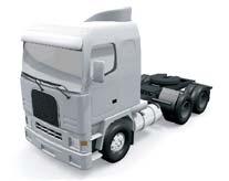
3 SKF Multilube central lubrication system General system description Safety instructions Operation Safemobe lubrication devices and systems are designed and manufactured for centralized and automatic lubrication of vehicles and machines. No other use is allowed. Pumps The pumps in central lubrication systems are pneumatically or electrically (12 V or 24 V DC) operated. When servicing the system, the operating power of the pump must be switched off. Piping, hoses and connectors Opening of piping, hoses, and connectors is allowed only when unpressurized. Before opening, make sure that you also switch off the operating power of the pump. Springs The lubricant reservoir contains a guide piston spring. Remember this when opening the reservoir! General information on centralized lubrication system Accurate lubrication prevents damages and shutdowns caused by inadequate lubrication. The service life of process equipment and machinery is extended and both energy consumption and the used amount of lubricant are reduced. Thanks to automation, optimum lubrication is achieved and the burden of the environment is minimized. All this brings savings. Automation increases work safety, as equipment and machinery does not have to be lubricated manually during operation. SKF Multilube-central lubrication system SKF Multilube system is a single- or dual-line (Heavy- or Twinheavy) central lubrication system, in which the lubricant is pumped through piping to the dosers. Dosers feed the preset amount of lubricant to the lubrication points. The system operation is controlled and monitored by a control unit. Control unit controls the system according to preset starting interval and monitors system pressurization and the amount of lubricant. If the pressure does not reach the preset value during the maximum pressurization time or if the amount of lubricant drops to the low level limit, the control unit will inform of a malfunction. The control unit has an interlocking feature. 1
4
5
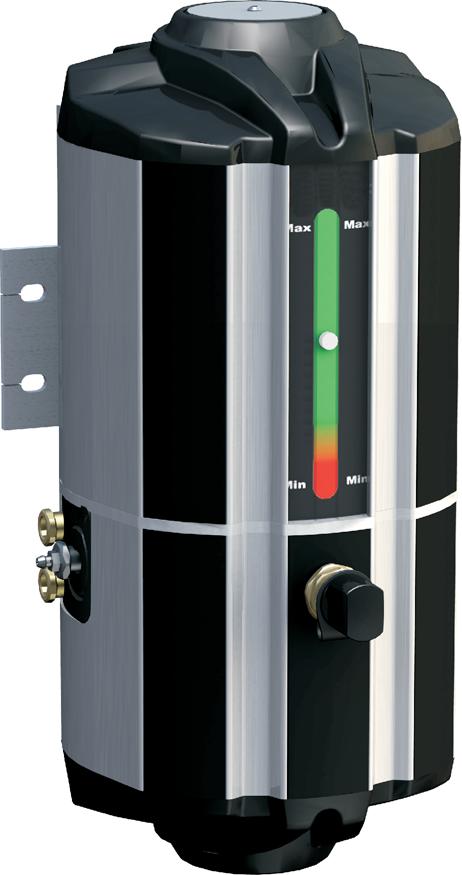
6 SKF Multilube pumping unit General description The pumping unit is designed for pumping lubricant into central lubrication system. Design Pumping unit comprises of a body (pos. 1) and a lubricant reservoir (pos. 2). The body comprises of a pump element (pos. 3), an electric motor (pos. 4), a line valve (pos. 5), a pressure relief valve (pos. 6) and a heating element (pos. 7). Pumping unit is controlled by a circuit board (pos. 8). (If external control is used, user interface and circuit board are replaced with relays.) Pumping unit is equipped with a pressure sensor (pos. 9) for each line which can be replaced with an external pressure control unit. Lubricant reservoir is equipped with a follower piston (pos. 10), a level indicator (pos. 11) and a low level switch (pos. 12). Filling connector (pos. 13) of the lubricant reservoir is equipped with a filter (pos. 14) and a safety valve (pos. 15). Pumping unit is equipped with a supporting block (pos. 16). 4
7 Operation When pressurization begins, the control starts the pump and opens the line valve. In pressure switch operation the pump stops, when the pressure switch closes and restarts, when the pressure switch opens. After the set pressurization time, the control stops the pump and pressure discharges from the line to the lubricant reservoir. If the lubricant level in the reservoir drops to the low limit level during pumping, the reservoir low level switch sends an alarm to the control and pumping is stopped. The alarm can be disabled by filling the lubricant reservoir and resetting the alarm. Filling the lubricant reservoir of the pumping unit Lubricant reservoir of the pumping unit is filled through the filling connector which is equipped with a filter. Use of filling device (Safematic code or ) 1. Ensure that the surroundings of the pumping unit are clean. Impurities in the system prevent trouble-free operation and cause damage when reaching the lubrication point. 2. Remove the lid from the lubricant reservoir (1) and press the follower plate (2) tightly to the reservoir above the lubricant. Follower plate is not used with fluid lubricants, as it does not remain on the surface. 3. Place the lid (3) on top of the lubricant reservoir. Fasten the lid with wing screws (4) on the lubricant reservoir. 4. Place the pump (5) through the lid into the follower plate central unit (6). 5. Connect the lubricant hose (7) to the pump. 6. Fill the lubricant hose by pumping by hand. 7. Connect the quick connector (8) to the lubricant hose. 8. Connect the quick connector to the pumping unit filling connector (9). 9. Fill the lubricant reservoir of the pumping unit by pumping slowly by hand. 10. Filling of the lubricant reservoir can be followed at the level indicator (10). To prevent overfilling, the pumping unit is equipped with a safety valve (11). 11. Turn the pump handle (12) to upright position so that pressure discharges to the lubricant reservoir. 12. Disconnect the quick connector from the pumping unit filling connector. 13. Fasten the protecting cap (13) of the pumping unit filling connector. 14. Fasten the protecting cap (14) of the filling device quick connector. 5
8 Caution Filter (15) of the filling connector has to be cleaned regularly and replaced if necessary. 6

9 Removing air from the pumping unit Remove air from the pumping unit, if there is air mixed with the lubricant e.g. in connection with the filling of the lubricant reservoir. Removing air from the pumping unit: 1. Disconnect the main line connections. 2. Start the pumping unit. 3. Open the pumping element deaerating screw. 4. Pump until only lubricant is coming out of the deaerating screw (no air). 5. Tighten the deaerating screw. 6. Connect the main line connections. Figure 1. Opening the deaerating screw 7
10 Technical specification 4 l reservoir 10 l reservoir Max. output 13 g/min 13 g/min Reservoir 4 l 10 l Max. pressure 250 bar / 3626 psi 250 bar / 3626 psi Operation temperature range -30 C +70 C / -22 F +158 F - 30 C +70 C / -22 F +158 F Lubrication line connections R 1/4 R 1/4 Lubricant Up to NLGI 2 Up to NLGI 2 Operating voltage 12/24 VDC 12/24 VDC Power consumption 150 W 150 W Protection classification IP65 IP65 Weight, (full reservoir) 16 kg / 44,1 lb 24 kg / 61,7 lb Height of pump 448 mm / 17, mm / 27,09 Width of 230 mm / 9, mm / 9,06 Depth of pump 235 mm / 9, mm / 9,25 Material Aluminium Aluminium Connections Input pressure switch, 2 pcs, closing contact or pressure transmitter, 2 pcs, 4 20 ma / bar, 2-wire type Output lubricant, 1 or 2 pcs, female thread R 1/4 8
11 Symbols MLP A B C D E Abbreviation Description MLP MLP Multilube-pump A 4 Lubricant reservoir volume, 4 l 10 Lubricant reservoir volume, 10 l B 1 Number of lines, 1-line system 2 Number of lines, 2-line system C 12 Power input 12 V 24 Power input 24 V D JB-103 User interface, JB-103 IF-103 User interface, IF-103 E PS Pressure control unit, built-in pressure switch PSE Pressure control unit, built-in pressure sensor Example: MLP JB103-PS Pressure control unit, built-in pressure switch User interface, JB-103 Power input, 24 V Number of lines, 2-line system Lubricant reservoir volume, 4 l MultiLube pump Spare parts See MLP-pumping unit spare parts (drawing no in the next page). 9
12
13 B-doser groups, Heavy-system General description Note Numbers in brackets are part numbers of drawings in the page 16. A doser group consists of a mounting rail (pos. 1) and one or several dosers (pos. 2) fastened to it. The mounting rail divides the lubricant to the dosers, which feed the adjusted amount of lubricant to the lubrication points. Design The doser includes a charging valve (pos. 3), a dosing chamber (pos. 4), a dosing piston (pos. 5) and a spring (pos. 6). B6 doser is equipped with a dosage adjustment screw (pos. 7). Operation B-doser The pressure in the line increases during pressurization and the doser charging valve moves to its upper position. At the same time lubricant flows past the charging valve and moves the dosing piston to its upper position. When the dosing piston moves to its upper position, it pushes the adjusted lubricant dosage from the dosing chamber to the lubrication point. After pressurization the line pressure decreases and the charging valve moves to its lower position and closes. The spring returns the dosing piston to its lower position and at the same time lubricant flows above the dosing piston to the dosing chamber. The line can be pressurized again when the pressure in the line has decreased and the dosing pistons of the dosers have returned to the lower position. The unfastening and fastening of dosers The dosers are unfastened and fastened with a socket wrench. Caution When changing the dosers, make sure that there is no pressure in the system. 11
14 Adjustments Adjustments of B6-doser 1. Turn open the pipe connector of the doser s lubrication piping outlet. 2. Turn open the locking nut in the upper part of the doser. 3. Adjust the dosage by turning the adjustment screw located above the locking nut. 4. Tighten the locking nut in the upper part of the doser. 5. Tighten the pipe connector of doser s lubrication piping outlet. Technical specification Technical specifications Tabel 1. Technical specifications for dosers Quantity Range Unit Description t C Operation temperature p max 150 bar Max. operation pressure w x h x d 15 x 90 x x 110 x 17 mm B1-B5 doser dimensions, B6 doser dimensions Connections Inlet, mounting rail lubricant (1 pc), header piping inlet, pipe connector Ø 8 mm Outlet, doser lubricant (1 pc), lubrication piping outlet, pipe connector Ø 4 mm or Ø 6 mm 12
15 Symbols Tabel 2. The symbols of dosers BX-xxx-Y-Z-U Abbreviation Description B: B Lubrication system type, B X: 1 Doser size, size 1 2 Doser size, size 2 3 Doser size, size 3 4 Doser size, size 4 5 Doser size, size 5 6 Doser size, size 6 xxx: R1/8 Fastening of doser to mounting rail R 1/8 Y: ZN Doser material, zinc-coated and yellow-passivated steel Z: 4 Lubricant outlet, pipe connector Ø 4 mm 6 Lubricant outlet, pipe connector Ø 6 mm Example: B2-R1/8-ZN-4 Lubricant outlet, pipe connector Ø 4 mm Doser material, zinc-coated and yellow-passivated Fastening of doser to mounting rail R 1/8 Lubrication system type, B; Doser size, size 2 13
16 Tabel 3. Doser codes Doser Code B1-R1/8-ZN B2-R1/8-ZN B3-R1/8-ZN B4-R1/8-ZN B5-R1/8-ZN B6-R1/8-ZN B1-R1/8-ZN B2-R1/8-ZN B3-R1/8-ZN B4-R1/8-ZN B5-R1/8-ZN B6-R1/8-ZN Tabel 4. Symbols of mounting rails BPLD-XX-YY Abbreviation Description BP: BP Mounting rail, Base Plate LD: LD Lubrication system type, LD XX: 02 2-place mounting rail : place mounting rail, 2 places for dosers on opposite sides place mounting rail, 3 places for dosers on opposite sides 04 4-place mounting rail 06 6-place mounting rail 08 8-place mounting rail place mounting rail, 8 places for dosers on opposite sides YY: ZN Mounting rail material, zinc-coated and yellow-passivated steel S Mounting rail material, stainless steel 14
17 Example: BPLD-04-ZN Mounting rail material, zinc-coated and yellow-passivated steel Mounting rail size, 4-place mounting rail Lubrication system type, LD Mounting rail, Base Plate Lubricant inlet, pipe connector Ø 8 mm Tabel 5. Mounting rail codes Mounting rail type Code BPLD-0202-ZN BPLD-0303-ZN BPLD-04-ZN BPLD-06-ZN BPLD-08-ZN BPLD-0808-ZN BPLD-02-S BPLD-0303-S BPLD-04-S BPLD-06-S
18
19 SMG-dosers, Twinheavy-system General description SMG-2 doser feeds the preset amount of lubricant to one to eight (1 8) lubrication points. Design The doser includes a disk valve (pos. 1) and a dosage cylinder (pos. 3) which is equipped with sealed piston (pos. 2). The movement of the piston is adjusted with the adjusting screw (pos. 4). The doser lubrication outlet connections (pos.5) are equipped with check valves (pos. 6). The design of the dosers makes it possible to feed small amounts of lubricant from dosers. Operation Dosers with two outlets During normal sequential operation, dosers with two outlets feed lubricant to opposite sides of the outlet connections. The pressure in the line 1 increases during pressurization and the disk valve moves to its extreme position, whereupon the lubricant moves the piston. When the piston moves, it pushes the lubricant through the check valve to the lubrication pipe or lubrication hose and further to the lubrication point P1. When the pumping starts again, the check valve directs the lubricant to line 2, whereupon the lubricant is directed to the opposite side of the piston. When the piston moves, it pushes the lubricant through the check valve and further to the lubrication point P2. 17
20 Dosers with one outlet The doser with two outlets is modified to doser with one outlet by removing the disk valve and the lubrication outlet connection and replacing them with blocking plug (pos. 7). During normal sequential operation, doser with one outlet feeds the lubricant in turns to lubrication outlet connection and to one of the main lines. The pressure in the line 1 increases during pressurization and the disk valve moves to its extreme position, whereupon the lubricant moves the piston. When the piston moves, it pushes the lubricant to the line 2. When the pumping starts again, the check valve directs the lubricant to line B, whereupon the lubricant is directed to the opposite side of the piston. When the piston moves, it pushes the lubricant through the check valve and further to the lubrication point P3. The unfastening and fastening of the doser Caution When changing the dosers, make sure that there is no pressure in the system. Adjustment General The lubricant dosage is adjusted by changing the movement of the piston with the adjusting screw. Doser adjustments SMG-dosers are adjusted with an allen screw, which is located inside of a metal cover. The other end of the allen screw is located in the dosage cylinder, so the adjustment affects direct to the piston. 1. Make sure that there is no pressure in the lines. 2. Remove the metal cover. 3. Turn the allen screw to its closing position. 4. Look at the adjustment graph for the number of adjustment screw turns that correspond to the desired lubrication dosage. 5. Turn the adjustment screw outward as many turns as instructed from the doser body. 6. Replace the cover. 18
21 DOSAGE (g) (grease density 0,88 g/cm3) ADJUSTMENT GRAPH max 1,32 1,2 1,0 0,8 0,6 0,4 min 0,13 0, TURNS OF ADJUSTMENT SCREW / L mm/turn Technical specification Technical specifications Tabel 6. Technical specifications of a doser group Value Range Unit Description t C Operation temperature range p max 200 bar Max. pressure Connections Input and output connections are in the doser body. Input lubricant (2 pcs), main line inputs, female thread R 1/8 Output lubricant (2 pcs), main line outputs, female thread R 1/8 lubricant (2-4 pcs), lubrication piping outputs, 1-4 pcs in both sides, outlet connection Ø 6 mm. 19
22 Symbols Tabel 7. The symbols of dosers SMG-X-Y-zz Abbreviation Description SMG: SMG The type of the lubrication system, SafeMobeGrease X: 2 Number of the lines, dual line Y: 1 Doser body size 1; 2 outlets 2 Doser body size 2; 4 outlets 4 Doser body size 4; 8 outlets zz: ZN Doser material, zinc-coated and yellow-passivated steel Example: SMG-2-1-ZN Doser material, zinc-coated and yellow-passivated steel Doser body size 1; 2 outlets Number of lines, 2-line Lubrication system type, SafeMobeGrease Lubricant outlet: pipe connector 6 mm Spare parts See SMG-doser spare parts (drawing ). 20
23
24 Operation of user interface JB-103 There are a SET-button and three LED-signals 1, 2 and P on the user interface JB-103. Normal functions Button for lubrication Depending on the lubrication program status the SET-button can be used for different functions: Lubrication program status Lubrication interval Pressurization Alarm Functions Extra lubrication Interruption of pressurization Alarm reset LED-signals When the power is on at the pump, one of the LED-signals 1, 2 or P (pos 2, 3 or 4) is always lit. Status. Function LED-signal 1 is lit. LED-signal 2 is lit. Lubrication interval, line 1 has been pressurized last. Lubrication interval, line 2 has been pressurized last. LED-signals 1 and P are lit. Pressurization is in progress in line 1. LED-signals 2 and P are lit. Pressurization is in progress in line 2. LED-signals 1 and 2 are lit. There is a waiting time of 30 seconds between an extra pressurization in line 1 and in line 2. or if the button for an extra lubrication is pressed immediately after an automatic lubrication. Led-signal 1 is flashing. Pressure alarm in line 1 LED-signal 2 is flashing. Pressure alarm in line 2 LED-signal P is flashing. Reservoir low level alarm None of the LED-signals is lit. The timer is turned off or there is a cable fault. Note If the power is switched off during pressurization, LED-signal 2 is lit for 10 s when the power is switched back on. This ensures that there is no pressure in the system when the pump starts. 22
25 Functions With SET-button lubrication interval, maximum pressurization time and the number of lines line, 1 or 2 (heavy or twinheavy lubrication system) can be set. Setting the lubrication cycle Press the SET-button for about 5 seconds in normal operation mode until the LED-signal 1 begins to flash quickly. Now lubrication interval can be set. The LED-signal P shows the current value of the lubrication cycle. P flashes 1 10 times. After that there is a pause of 2 seconds and P will again flash times. The current set value of the lubrication cycle can be found in the following table. Flashes Lubrication cycle minutes) Setting of lubrication cycle changes from smaller to bigger by pressing the button according to the table. After reaching the biggest reading unit, start again from the beginning of the table. Return from the setting mode of lubrication cycle and save a new setting by pressing the SET-button for 5 seconds until all three LED-signals are lit. Note To exit setting mode without saving settings, switch off operating voltage for Multilube for a moment. Setting the maximum pressurization time Press SET-button for 10 seconds in normal operation mode until the LED-signal 2 begins to flash quickly. Now max. pressurization time can be set. The number of flashes of LED-signal P shows the current lubrication cycle according the following table. 23
26 Flashes Max pressurization time (minutes) Setting of pressurization time changes from smaller to bigger by pressing the button. After reaching the biggest reading unit, start again from the beginning of the table. Return from setting mode of pressurization time and save a new setting by pressing the SET-button for 5 seconds until all three LED-signals are lit. Note To exit setting mode without saving settings, switch off operating voltage for Multilube for a moment. Setting of the lubrication system Press SET-button for 15 seconds in normal operation mode until the LED-signals 1 and 2 begin to flash quickly. Now you can select the lubrication system. Single- or dual-line lubrication system can be selected. When the single-line system is selected P LED-signal flashes once and alternatively when the dual-line system is selected P LED-signal flashes twice before a pause for 2 seconds. The system can be selected with the button. Return from setting mode of lubrication system and save a new setting by pressing the SET-button for 5 seconds until all three LED-signals are lit Note To exit setting mode without saving settings, switch off operating voltage for Multilube for a moment. Settings, general If the button is left in the setting mode, it returns to normal mode automatically after 3 minutes without saving new settings. 24
27
28 Multilube-system monitoring General Daily inspections control unit for trouble-free operation Monthly inspections check piping in locations which are exposed for external damages Annual inspections (more often if needed) cleaning of the filter of the filling connector Doser inspections Check the dosers after approximately one (1) month after system start-up and after that check depending on the operating conditions, but at least after every 6 months. Check for potential excessive or insufficient lubrication and adjust dosers, if necessary. SMG dosers Steps 1. Disconnect the lubrication pipes and hoses from the lubrication points. 2. Pressurize the lines. 3. Check that lubricant comes out of the lubrication pipes and hoses. 4. Connect the lubrication pipes and hoses to the lubrication points. If lubricant does not come out of lubrication pipes or hoses, see Multilube / Troubleshooting. B-dosers Steps 1. Disconnect the lubrication pipes and hoses from the lubrication points. 2. Pressurize the line. 3. Check that lubricant comes out of the lubrication pipes and hoses. 4. Connect the lubrication pipes and hoses to the lubrication points. If lubricant does not come out of lubrication pipes or hoses, see Multilube / Troubleshooting. 26
29 Choosing the lubricant Traditionally, equipment or bearing manufacturers recommend a lubricant based on manual lubrication. Characteristics of manual lubrication are large amounts of lubricant and long intervals between lubrications. This means that in addition to the lubricating quality, another requirement for the lubricant is durability at the lubrication point. Characteristics of centralised lubrication are small amounts of lubricant and short intervals between lubrications with each lubrication point fed separately. In this case, choose the lubricant according to the basic oil viscosity, additives and thickening agent recommended by the manufacturer while ensuring that the lubricant can be pumped at the operating temperature and that its pressure tolerance is adequate. A lubricant fed with short intervals also removes impurities very efficiently from the lubrication point. New lubricant displaces the used grease and the moisture, dirt and wear remains it has collected. A lubricant is composed of basic oil, thickening agent and additives. The basic oil, forming the majority of the composition of a lubricant, determines the properties of the lubricant. The basic oil together with the thickening agent determines the rheological properties of the lubricant. (Rheology = a science dealing with the deformation and flow of matter.) The viscosity of the basic oil is a temperature-dependent magnitude that indicates the fluidness of liquid: the smaller the viscosity value, the more fluid the basic oil is. By choosing the correct lubricant and lubrication system settings, you can also prevent semi-fluid lubricant from running out from the lubrication point. For Safematic HEAVY lubrication systems, we recommend grade NLGI 00-1 lubricants in summer and grade NLGI 00-0 lubricants in winter. For Safematic TWINHEAVY systems, we recommend max. grade NLGI 2 lubricants in summer and max. grade NLGI 1 lubricants in winter. When choosing a lubricant, you should pay attention to the viscosity of the basic oil and the high quality of the lubricant in addition to the NLGI classification. Note Check the lubricant requirements from the manufacturer of the vehicle and the properties of the lubricant from the lubricant manufacturer. Note that in addition to the application, also operating temperature, rotation speed and operating environment are relevant factors in choosing the lubricant. For more information on pumping of different lubricants, contact Oy SKF Ab. 27
30 SKF Multilube-system troubleshooting System troubleshooting User interface does not operate Operation disturbance Display and LED signals of user interface are not lit. Cause of operation disturbance No supply voltage on pumping unit. Solution Check supply voltage. User interface triggers an alarm Operation disturbance The P LED-signal of user interface is blinking The LED-signal 1 or 2 for line is blinking at the user interface. Cause of operation disturbance Lubricant reservoir is empty. Header piping leaks. There is air in the pumping unit or in the header piping. Solution Fill the lubricant reservoir. Reset the alarm. Locate and repair the leakage. Remove air from the pumping unit or from the header piping. Reset the alarm. Wrong lubricant. See " choosing the lubricant " 28
31 A lubrication point gets too little lubricant or nothing at all Operation disturbance The rotation of the bearing makes noise, is trembling or the temperature is rising. Doser does not operate Cause of operation disturbance The dosage adjustment of the doser is too small. The lubrication point has clogged. Solution Increase the dosage. Clean the lubrication point. Lubrication pipe or hose has clogged. Clean or replace lubrication pipe or hose. Grease leakage in the area of lubrication piping. The doser is damaged. Lubrication piping between the doser and lubrication point is damaged. Replace the doser. Check and repair the lubrication piping. A lubrication point gets too much lubricant Operation disturbance Considerable grease leakage in the lubrication point. Cause of operation disturbance The dosage adjustment of the doser is too large. Solution Adjust the dosage to a smaller amount. The temperature of the bearing rises. The doser is damaged. Replace the doser. Warnings Caution The lubrication disturbances of the critical lubrication points must be repaired immediately, since inadequate lubrication rapidly damages the equipment or machinery being lubricated. Note In the event that the operation disturbance can not be repaired with the help of these instructions, please contact the supplier immediately. 29
32 Contact information Oy SKF Ab P.O. BOX MUURAME Finland Tel Fax
MLP2 - DUAL-BRANCH LUBRICATION SYSTEM
 - DUAL-BRANCH LUBRICATION SYSTEM TABLE OF CONTENTS 1 GENERAL SYSTEM DESCRIPTION...1 1.1 General information on automatic centralized lubrication system...1 2 SYSTEM DESIGN...1 3 SYSTEM OPERATION...1 4
MULTILUBE SYSTEM INSTALLATION AND MAINTENANCE
 MULTILUBE SYSTEM TABLE OF CONTENTS 1 PUMPING UNIT INSTALLATION...1 1.1 Installing the supporting blocks and the pumping unit...1 1.2 Installing the main line on the pumping unit...3 1.3 Installing the
SKF Electro-pneumatic Barrel Pump EPB-Pump-ECO (Original operating and maintenance instructions according to EU Directive 2006/42/EC)
") SKF Electro-pneumatic Barrel Pump EPB-Pump-ECO (Original operating and maintenance instructions according to EU Directive 2006/42/EC) TABLE OF CONTENTS 1 EC Declaration of incorporation...1 2 General description...2
SKF Electro-pneumatic Barrel Pump EPB-Pump-ECO (Original operating and maintenance instructions according to EU Directive 2006/42/EC) TABLE OF CONTENTS 1 EC Declaration of incorporation...1 2 General description...2
SKF Multilube pumping unit. for single-, dual-line and progressive lubrication systems
 SKF Multilube pumping unit for single-, dual-line and progressive lubrication systems SKF Multilube pumping unit The SKF Multilube pumping unit is an effective solution for lubricating individual machines
SKF Multilube pumping unit
 SKF Multilube pumping unit for heavy vehicle lubrication systems SKF Multilube pumping unit SKF centralised lubrication systems are an effective solution for lubrication maintenance of heavy vehicles.
SKF Maxilube pumping centre. for SKF DuoFlex, dual-line lubrication systems
 SKF Maxilube pumping centre for SKF DuoFlex, dual-line lubrication systems SKF Maxilube pumping centre for trouble-free production Accurate lubrication prevents damage and shutdowns caused by inadequate
SGA and SG-dosers. for SKF DuoFlex dual-line lubrication systems
 SGA and SG-dosers for SKF DuoFlex dual-line lubrication systems Modular and mechanical adjustable SGA and SG-doser are used in SKF DuoFlex applications. SGA and SG-dosers The dosing modules are hydraulically
for SKF DuoFlex dual-line lubrication systems
 SGA and SG-dosers for SKF DuoFlex dual-line lubrication systems Modular and mechanically adjustable SGA and SG-dosers are used in SKF DuoFlex applications. SGA and SG-dosers The dosing modules are hydraulically
16000SIII Automatic Grease System
 Manual # 99905495 16000SIII Automatic Grease System Effective 20120716 IOWA MOLD TOOLING CO., INC. PO Box 189 Garner, IA 50438 Tel: 641-923-3711 FAX: 641-923-2424 Website: http://www.imt.com Copyright
Models CHASSIS LUBE ELECTRIC GREASE PUMP Series "C" - 13C MAY FORM Page. Section - Q3
 Models 94422 CHASSIS LUBE ELECTRIC GREASE PUMP Series "C" MAY - 2004 FORM 403467 Section - Q3 Page - 13C 9.00" (229 mm) 13.75" (350 mm) 0.35" (9mm) Mounting Holes 4.76" (121 mm) 9.84" (250 mm) Do not use
Models CHASSIS LUBE ELECTRIC GREASE PUMP Series "C" - Q3. MAY FORM Section
 Models 94822 CHASSIS LUBE ELECTRIC GREASE PUMP Series "C" - Q3 MAY - 2004 FORM 403468 Section Page - 14B 13.00" (330 mm) 17.72" (450 mm).35" (9 mm) Mounting Holes 4.72" (120 mm) 9.84" (250 mm) Figure 1
Model CHASSIS LUBE ELECTRIC GREASE PUMP Series "C"
 Model 94222 CHASSIS LUBE ELECTRIC GREASE PUMP Series "C" Indicates change MAY - 2004 FORM 403466 Section - Q3 Page - 12B 7.75" (197 mm) 12.6" (321 mm) 0.35" (9 mm) Mounting Holes 4.85" (123 mm) 8.85" (225
Owner s and Maintenance Manual for: Lincoln QuickLub Systems
 Owner s and Maintenance Manual for: Lincoln QuickLub Systems Contents: I. Introduction 1. System Operation 2. Components II. Pump Mounting and Wiring 1. Power 2. Testing III. Purging and Testing IV. Programming
MultiPort II Lubricator
 MultiPort II Lubricator Mobile, Progressive, Grease General The MultiPort II Lubricator is an electrically driven multiple outlet lubrication unit designed primarily for use with progressive divider valve
User Guide. Lubricus Lubrication System LUB-D1/LUB-D2/LUB-D3/LUB-D4 (24 VDC)
") User Guide Lubricus Lubrication System LUB-D1/LUB-D2/LUB-D3/LUB-D4 (24 VDC) version 04/2013 Content General Information 3 Warning 3 Scope of Supply 3 Overview 3 General safety details 4 Intended use 4
User Guide Lubricus Lubrication System LUB-D1/LUB-D2/LUB-D3/LUB-D4 (24 VDC) version 04/2013 Content General Information 3 Warning 3 Scope of Supply 3 Overview 3 General safety details 4 Intended use 4
MultiPort Lubricator. Electric motor-driven, Grease and Oil. General. Technical Data. Motor R6 08/17
 MultiPort Lubricator Electric motor-driven, Grease and Oil General The MultiPort Lubricator is a rugged, motor-driven, electric lubricator, equipped with fixed or adjustable output pumping elements to
MultiPort II Lubricator
 MultiPort II Lubricator Mobile, PDI, Grease General The MultiPort II Lubricator is an electrically driven multiple outlet lubrication unit designed primarily for use with positive displacement injector(pdi)
Dual-line lubrication systems. Pumps and pump units. Grease. SKF Maxilube Lubrigun PowerMaster III PUB LS/P EN
 Dual-line lubrication systems Pumps and pump units HJ 2 SKF Multilube ZPU 01/02 FK ZPU 08/14/24 EPB pump SKF Maxilube Lubrigun PowerMaster III 10 Overview of grease pumps and pump units Manually operated
Operating manual UPS - System
 Operating manual UPS - System POWERMASTER M MIL 1000VA 7Min. BAX 3330 E UPS-Division Issued 15. August 2006 JOVYATLAS JOVYATLAS Elektrische Umformtechnik GmbH Groninger Straße 29-37 D-26789 Leer/Ostfriesland
MultiPort Lubricator. Electric motor-driven, Grease and Oil. General. Technical Data. Motor R3 09/09
 MultiPort Lubricator Electric motor-driven, Grease and Oil General The MultiPort Lubricator is a rugged, motor-driven, electric lubricator, equipped with fixed output pumping elements to discharge grease
MultiPort Lubricator. Electric motor-driven, Grease and Oil. General. Technical Data. Motor R8 08/18
 MultiPort Lubricator Electric motor-driven, Grease and Oil General The MultiPort Lubricator is a rugged, motor-driven, electric lubricator, equipped with fixed or adjustable output pumping elements to
ILC PICO-MAX ELECTRIC GREASE PUMP Automatically Lubricates Small, Medium and Large Machinery
 Automatically Lubricates Small, Medium and Large Machinery Programmable Multi-Functional Lubricator 2 Outlet injection feeds for Progressive Distributors Up to 8 direct outlet injectors feeds The compact
Techcon Systems TS500R-PC Controller For Positive Displacement PC Pump
 Techcon Systems TS500R-PC Controller For Positive Displacement PC Pump Copyright OK International CONTENTS Page Number 1. Safety 3 2. Symbol Definitions.. 3 3. Specifications... 4 4. Features.. 5 5. Setup
Operators Manual SUREFIRE II Single Phase PDI - SLR (24VDC, 115VAC & 230VAC) r#3
 r#3") Operators Manual SUREFIRE II Single Phase PDI - SLR (24VDC, 115VAC & 230VAC) 36412 r#3 Contents Precautions & Symbols...2 Manufacturer s Statement...2 General...2 Features...2 Operation...3-4 Technical
Operators Manual SUREFIRE II Single Phase PDI - SLR (24VDC, 115VAC & 230VAC) 36412 r#3 Contents Precautions & Symbols...2 Manufacturer s Statement...2 General...2 Features...2 Operation...3-4 Technical
Twin Power. Manual. Pneumatic Multiturn actuator in Standard and ATEX design WARNING! WARNING! Mounting. Assembly example
 Top Quality Valve Actuators Made in Sweden Twin Power Manual Pneumatic Multiturn actuator in Standard and ATEX design Mounting The Twin Power actuator works beyond reproach in all positions. Valves with
Purging Air From Divider Block Lubrication Systems
 FROST ENGINEERING SERVICE Purging Air From Lubrication Systems A D I V I S I O N O F G E C S E Y S A L E S & S E R V I C E DESCRIPTION Divider block lubrication systems operate correctly only when all
Pressure chlorine changeover unit C 7520
 BW 2 24 04 / 1 Content 1. Scope of delivery 2. Device description 3. Installation 4. Operation 5. Shutdown 6. Maintenance 7. Troubleshooting 1 Scope of delivery The chlorine gas changeover unit C 7520
GREASE NLGI (*) OIL CST (*) PRESSURE (220.5) (147) - 20 (294) (220.5)
 OIL CST (*) PRESSURE (220.5) (147) - 20 (294) (220.5)") CHARACTERISTICS THREE TYPES OF THREADING AVAILABLE: BSP, NPTF, SAE : UP TO 500 BAR : UP TO 400 BAR OIL AND GREASE FUNCTION CE AND ATEX MARKINGS BASES ALWAYS SUPPLIED WITH STANDARD SEALS AND MOUNTING SCREWS
CHARACTERISTICS THREE TYPES OF THREADING AVAILABLE: BSP, NPTF, SAE : UP TO 500 BAR : UP TO 400 BAR OIL AND GREASE FUNCTION CE AND ATEX MARKINGS BASES ALWAYS SUPPLIED WITH STANDARD SEALS AND MOUNTING SCREWS
Trouble Shooting Manual Progressive Systems
 1 INTRODUCTION The information contained in this manual provides insight in how a progressive grease distribution system works and how to trouble shoot a progressive system. 2 OPERATING PRINCIPLE Any pump
Table of contents. Table of contents. Overview of progressive distributor Distributor bridge without outlet...
 Table of contents 4 Technical basics System description... 04-0-10-01 Construction, applications, advantages, function System design... 04-0-10-02 Design and installation of progressive systems Calculation
Farval. Dualine Installation System Start-Up. Bulletin DL300 BIJUR DELIMON INTERNATIONAL
 Farval Dualine Installation System Start-Up Bulletin DL300 BIJUR DELIMON INTERNATIONAL 2685 Airport Road Kinston, NC 28504 Tel. 800-227-1063 Fax: 252-527-9232 website: www.bijurdelimon.com DC1-1 SECTION
OK-01 TRAM WHEEL FLANGE LUBRICATION APPLICATION DESCRIPTION
 TRAM WHEEL FLANGE LUBRICATION APPLICATION The lubrication system is designed for lubricating wheel flanges of trams that are not equipped with pressure air distribution. The system works on the principle
Type 3360, Service Manual. Serviceanleitung Service Manuel
 Electromotive control valve Elektromotorisches Regelventil Vanne de régulation électromotorisée Service Manual Serviceanleitung Service Manuel We reserve the right to make technical changes without notice.
LUBRICATION PUMP PMP CENTRAL LUBRICATION
 LUBRICATION PUMP APPLICATION The lubrication pump is used as a pressure lubricant source for central lubricating systems with progressive distributor types BVA, PRA and PRB, for permanent, regular lubrication
Lubrication systems & equipment for Mining and Construction machinery
 Almost a century of experience. High quality products. The best world grid of services. For the mining industry which never stops and the machines must continue in operation in the most hardworking conditions,
Operating Instructions
 Operating Instructions Lubricus Lubrication System LUB - M (24 VDC) Operating Instructions: LUB- M Table of Contents Contents 2 1) General Information 4 1.1 Warning 4 1.2 Scope of supply 4 1.3 Overview
ESCONDIDO FIRE DEPT TRAINING MANUAL Section DRIVER OPERATOR Page 1 of 13 Pumps and Accessory Equipment Revised
 DRIVER OPERATOR Page 1 of 13 PUMPS AND ACCESSORY EQUIPMENT Pumps are designed for many different purposes. In order to understand the proper application and operation of a pump in a given situation, firefighters
Automated Lubrication System
 Automated Lubrication System Installation/Operator Instructions Case IH RBX2 Series Baler Contents Pages Introduction 3 Preparation 4 Bill of Material 5 Component Appendix 6-9 System Operation 10 Valve
AIR CLEANERS Model MC 3000 OWNER S MANUAL CAUTION Read complete instructions before operating. Please file for future reference.
 AIR CLEANERS Model MC 3000 OWNER S MANUAL CAUTION Read complete instructions before operating. Please file for future reference. MODEL MC 3000 SPECIFICATION Input Volts: 208-230/430 VAC, 60Hz, 3 Phase
Progressive distributor SXE-2
 The progressive piston distributors SXE-2 are distribution units with hydraulic sequence control, whose pistons are controlled by the lubricant supply so that the lubricant is forced in sequence through
Type 3320, Service Manual. Serviceanleitung Service Manuel
 Electromotive 2/2-way valve Elektromotorisches 2/2-Wege-Ventil Vanne électromotorisée à 2/2 voies Service Manual Serviceanleitung Service Manuel We reserve the right to make technical changes without notice.
SKF Grease Filler Pumps LAGF series
 Optimum cleanliness when filling your grease guns SKF Grease Filler Pumps LAGF series Best lubrication practices say that each type of grease requires an individual grease gun and the refilling has to
VC-4820 Programmable DC-DC Converter with Battery Charger function USER'S MANUAL
 1. INTRODUCTION VC-4820 Programmable DC-DC Converter with Battery Charger function USER'S MANUAL This MCU controlled Step Down DC-DC Converter has a digitally adjustable output in 0.2V increments. This
WATERFLUX 3070 Quick Start
 WATERFLUX 3070 Quick Start Battery powered electromagnetic water meter Electronic Revision ER 4.3.0_ up to ER 4.3.4_ (SW.REV 4.2.2_ up to 4.2.5_) KROHNE CONTENTS WATERFLUX 3070 1 Safety instructions 4
Service Handbook. High-Pressure Washer Pump
 Pump 629 9/28/01 3:22 PM Page 1 Service Handbook High-Pressure Washer Pump 3.532-629.0 10.00 Pump 629 9/28/01 3:22 PM Page 2 Pump 629 9/28/01 3:22 PM Page 3 TROUBLESHOOTING OVERVIEW How to Use This Manual
Operating Instructions
 Page 1 of 11 CONTENTS 1 PURPOSE... 3 2 APPLICATION... 3 3 DESCRIPTION... 3 4 FUNCTION... 5 5 TECHNICAL PARAMETERS... 5 6 TYPE IDENTIFICATION KEY MMP... 6 7 DIMENSIONAL DRAWING... 7 8 HYDRAULIC DIAGRAM...
Technical Manual. Installation Instructions Safety Notices Programming Operation
 Technical Manual Installation Instructions Safety Notices Programming Operation Congratulations We congratulate you on your purchase of this electronic additive dosing system Electronic Valve Protector
SureFire II Lubricator
 SureFire II Lubricator Automatic, Oil & Fluid Grease, Single Phase General The SureFire II Lubricator is an automatic, robust and durable pump. Its compact size is designed to fit your space requirements
Frequently Asked Questions
 Frequently Asked Questions Q.1 How to check if the lubricator is working in normal condition? Ans.: 1.1 To test whether Easylube is in a working condition, set all four DIP switches to ON position in TEST
Thunder Power Tarp Kit Operation
 Thunder Power Tarp Kit Operation Dual Arm Curb Side Stowing Single Arm Curb Side Stowing 011-52476 Rev. H P a g e 2 In this booklet you will find: OPERATING INSTRUCTIONS... 3 Powering up or down the system...
Routine Compressor Maintenance
 Establishing a regular, well-organized maintenance program and strictly following it is critical to maintaining the performance of a compressed air system. One person should be given the responsibility
PRODUCT OPERATING MANUAL
 PRODUCT OPERATING MANUAL PANBLAST TM CS37 SUCTION BLAST CABINET Manual Number: ZVP PC 0069 00 SECTION 1. GENERAL INFORMATION 2. ASSEMBLY & INSTALLATION INSTRUCTIONS 3. OPERATING INSTRUCTIONS 4. MAINTENANCE
Instruction Manual. Sewage lifting station compli 300
 Instruction Manual Sewage lifting station compli 300 Safety instructions Areas of application Electrical connection Installation Servicing Technical data Appendix JUNG PUMPEN GmbH Industriestr. 4-6 33803
ACF5. Std Line. Product Description. Max differential pressure: 16 bar Circulation, lubrication and transfer ACF GB
 ACF5 Std Line Product Description Flow volume: 310-2900 l/min Max differential pressure: 16 bar Applications: Circulation, lubrication and transfer 1. Applications 1.1 Functionality The ACF pumps are used
PRESSURE GOVERNOR, ENGINE MONITORING, AND MASTER PRESSURE DISPLAY MODEL DDA100
 PRESSURE GOVERNOR, ENGINE MONITORING, AND MASTER PRESSURE DISPLAY MODEL DDA100 1 CONTENTS Table of Contents CONTENTS... 2 INTRODUCTION... 4 Overview... 4 Features... 4 GENERAL DESCRIPTION... 5 2 List of
THE REVOLUTIONARY P653S ELECTRIC CENTRO-MATIC PUMP
 Lincoln The Industry Leader Since 1910 The Heart of a Centro-Matic Automated Lubrication System The P653S is the central pump station that automatically delivers lubricant through a single supply line
P445 Series Electronic Lube Oil Control
 FANs 125, 121 s Section P Product/Technical Bulletin P445 Issue Date 0100 P445 Series Electronic Lube Oil The P445 Series Electronic Lube Oil is designed for use on refrigeration compressors equipped with
Automated Lubrication System
 Automated Lubrication System Operator s Guide Lexion 700 Series Combine Rev. 1, 7/11, CWA Contents Pages Introduction 3 Component Appendix 4-6 Glossary f Terms 7-8 System Operation 9 Valve Operation 10-11
Battery Powered Hydraulic Pump; Kit PN [ ]
![Battery Powered Hydraulic Pump; Kit PN [ ]](/thumbs/73/68120284.jpg "Battery Powered Hydraulic Pump; Kit PN [ ]") ORIGINAL INSTRUCTIONS Battery Powered Hydraulic Pump; Kit PN 1804111-[ ] Customer Manual 409-10060 16 NOV 16 Rev D SAFETY PRES IMPORTANT SAFETY INFO READ THIS FIRST!... 2 SAFETY PRES AVOID INJURY READ
ORIGINAL INSTRUCTIONS Battery Powered Hydraulic Pump; Kit PN 1804111-[ ] Customer Manual 409-10060 16 NOV 16 Rev D SAFETY PRES IMPORTANT SAFETY INFO READ THIS FIRST!... 2 SAFETY PRES AVOID INJURY READ
Click Here for Printable PDF File. CHAPTER 3 - BASIC INFORMATION for PERFORMING HYDRAULIC SYSTEM MAINTENANCE
 HWH Online Technical School Lesson 1: Introduction to Hydraulics Chapter 3 - "BASIC INFORMATION for PERFORMING HYDRAULIC SYSTEM MAINTENANCE" (Filename: ML57000-012-CH3.DOC Revised: 22APR16) Click Here
Technical Service Bulletin IOX/DCX Transmitter Maintenance Schedule
 Technical Service Bulletin 140610 IOX/DCX Transmitter Maintenance Schedule Service Bulletin 140610 applies to Comark IOX, DCX and Paragon transmitters. This bulletin contains important maintenance schedule
PRESSURE GOVERNOR, ENGINE MONITORING, AND MASTER PRESSURE DISPLAY MODEL: TCA100
 Document Number: XE-TCA1PM-R0A TCA100 Rev0511 PRESSURE GOVERNOR, ENGINE MONITORING, AND MASTER PRESSURE DISPLAY MODEL: TCA100 FIRE RESEARCH CORPORATION www.fireresearch.com 26 Southern Blvd., Nesconset,
OPTIONS AUTOMATIC LUBRICATION SYSTEM
 OPTIONS AUTOMATIC LUBRICATION SYSTEM The central lubrication of the axes modules consists of a small lubricant dispenser with progressive distributor with several exits. It is responsible for the automatic
TABLE 1: COMPARISON OF GREASE AND OIL LUBRICATION. housing structure and sealing method. speed. cooling effect. removal of foreign matter
 TECHNICAL INSIGHT PRODUCT AND APPLICATION ENGINEERING INFORMATION A PUBLICATION OF NSK AMERICAS LUBRICATION - OPTIMIZING BEARING LIFE Lubrication is a critical component to extending bearing life. Without
OPERATION INSTRUCTIONS GFA-W-150\300\500\1000
 OPERATION INSTRUCTIONS HORIZONTAL SELF-SUCTION FILLER SERIES GFA-W-10\300\00\1000 Please operate in accordance with the instructions strictly. CONTENTS Overview Maintenance and Service Application Replacement
OPERATING INSTRUCTIONS & SERVICE MANUAL BLUE MAX II HYDROSTATIC TEST PUMP
 PAGE 1 OF 10 OPERATING INSTRUCTIONS & SERVICE MANUAL BLUE MAX II HYDROSTATIC TEST PUMP EFFICIENT, EASY OPERATION Air operated pump Wide range of pressures and volumes Easy to operate controls Output pressure
EUGEN WOERNER GmbH & Co. KG Postfach 1661 DE Wertheim Am Eichamt 8 DE Wertheim. Pump unit GMZ-E
 Pump unit GMZ-E Pump used to supply oil and grease from a barrel directly through a lid-hole or a bunghole. Technical data: Pump with bung-hole Pump with barrel lid Delivery volume per stroke: Pump element
Doc. No. NDP 173M-05 MAINTENANCE MANUAL YAMADA AIR-OPERATED DIAPHRAGM PUMPS. DP-15 series
 Doc. No. NDP 173M-05 MAINTENANCE MANUAL YAMADA AIR-OPERATED DIAPHRAGM PUMPS DP-15 series WARNING For your own safety, be sure to read procedures carefully before performing maintenance on this product.
Single Stage Rotary Vane Vacuum Pump Installation and Operation Manual RX-10 RX-21 RX-25
 V acuum Pumps Single Stage Rotary Vane Vacuum Pump Installation and Operation Manual RX-10 RX-21 RX-25 www.republicsales.com Revised 10.14 2014 Republic Sales & Manufacturing Single Stage Rotary Vane Vacuum
LUBRICATION PUMP SAO, SAG
 LUBRICATION PUMP APPLICATION Lubricating pump sets, SAO for lubricating oils, and SAG for soft-grease, are used as a source of pressurised lubricant, oil or soft-grease, for single-line central. Lubricating
MACHINE TOOLS. Automatic Lubrication Systems and Components STEEL AND ALUMINIUM PAPER & WOOD INDUSTRY MARINE AND OFFSHORE FOOD AND BEVERAGE SYSTEMS
 Automatic Lubrication Systems and Components STEEL AND ALUMINIUM PAPER & WOOD INDUSTRY MACHINE TOOLS MARINE AND OFFSHORE FOOD AND BEVERAGE SYSTEMS ENERGY AGRICULTURAL MACHINERY MQL - NEAR-DRY MACHINING
OWNER S TECHNICAL MANUAL
 OWNER S TECHNICAL MANUAL Electronic Oil Meter 660 Description Oval gear type Hose end meter with electronic LCD display for Lubricants and Anti-Freeze fluid. The Hose end meter includes a progressive opening
Progressive Central Lubrication System
 Progressive Central Lubrication System APPLICATION Centralized lubrication systems with progressive distributors preferably serve the lubrication of machinery. The lubrication capacity is up to approx.
Gel Gun Manual
 600-000-0 Gel Gun Manual Safety & Maintenance Airofog Gel Gun is designed utilizing the theory of negative pressure. Gel bait is sucked through the gun instead of the more traditional pushing method using
LUBRICATION PUMP PMP CENTRAL LUBRICATION
 LUBRICATION PUMP USE OF LUBRICATION PUMP The lubrication pump is used as a pressure lubricant source for central lubricating systems with progressive distributor types BVA, PRA and PRB, for permanent,
CENTRO-MATIC PUMP, MODELS 84050, & 85460
 CENTRO-MATIC DEC - 2006 Section - C8 - C8 Page - 142S Table of Contents Page Safety...2 Specifications...2 Description...2 Pump Operation...2 Installing the Pump...2 Optional Devices......3 Puffing Pump
Service Guide. High-Pressure Grease Pump. 100 psi (6.8 bar) High-Pressure Pump Model 7785 Series Specifications
 High-Pressure Pump Model 7785 Series Specifications") Description Service Guide 7785-A5 7785-B5 7785-MA The major components of the pump models in the 7785 series consist of an air-operated motor and a pump tube. The air motor connects directly to the double-acting
Description Service Guide 7785-A5 7785-B5 7785-MA The major components of the pump models in the 7785 series consist of an air-operated motor and a pump tube. The air motor connects directly to the double-acting
operation manual DUFT-TEC Solo (11//05)
") operation manual DUFT-TEC Solo (11//05) page 1 of 8 DUFT-TEC Solo Table of contents Page 1. Function... 2 2. Technical data... 2 3. The fragrance pump... 2 3.1 Changing the hose set... 3 3.2 Dosing valve...
operation manual DUFT-TEC Solo (11//05) page 1 of 8 DUFT-TEC Solo Table of contents Page 1. Function... 2 2. Technical data... 2 3. The fragrance pump... 2 3.1 Changing the hose set... 3 3.2 Dosing valve...
PNEUMATICS CONTENTS HST-TAMPER
 CONTENTS Tamper Pneumatic Component Locations...2 Manually Releasing Air Brakes... 3 Releasing Air Pressure... 4 Removing Water from Air Tanks... 4 Adjusting Air Compressor Governor... 4 Check/Replace
User's Manual. MV100 Rechargeable Battery Model. Yokogawa Electric Corporation. IM MV100-41E 1st Edition
 User's Manual MV100 Rechargeable Battery Model Yokogawa Electric Corporation 1st Edition Thank you for purchasing the MV100 Rechargeable Battery Model. This user s manual describes the rechargeable batteries.
Flow limiter SP/SMB 8... DSK US (09.04)
") DSK 0-050-08-US (09.04) for mounting plates General information s are used in large oil circulation lubrication systems. The task of a flow limiter is to divide up the volumetric flow of the main line
DSK 0-050-08-US (09.04) for mounting plates General information s are used in large oil circulation lubrication systems. The task of a flow limiter is to divide up the volumetric flow of the main line
20 Series. Simplify your pumping needs. s Adhesive Supply Servo Pump:
 20 Series Model 20-02-06 Adhesive Supply Servo Pump Simplify your pumping needs. s Model 20-02-06 Adhesive Supply Servo Pump allows excessive adhesive pressure to self-release back into the pump on shutdown
ACF5. Std Line. Product Description. Max differential pressure: 16 bar Circulation, lubrication and transfer
 ACF5 Std Line Product Description Flow volume: 310-2900 l/min Max differential pressure: 16 bar Applications: Circulation, lubrication and transfer ALSO VALID FOR PUMP SERIES UCF Generation 5 1. Applications
OWNER S TECHNICAL MANUAL
 OWNER S TECHNICAL MANUAL 2.5kg Grease Kit 6336 Description The Champion 6336 2.5kg grease kit is a manually operated, spring powered grease kit that comes complete with a hand piece. It is designed to
OPERATING MANUAL Digital Diesel Control Remote control panel for WhisperPower generator sets
 Art. nr. 40200261 OPERATING MANUAL Digital Diesel Control Remote control panel for WhisperPower generator sets WHISPERPOWER BV Kelvinlaan 82 9207 JB Drachten Netherlands Tel.: +31-512-571550 Fax.: +31-512-571599
Progressive Central Lubrication Systems
 Table of contents 4 Technical basics System description... 04-0-0-0 Construction, applications, advantages, function System design... 04-0-0-02 Design and installation of progressive systems Calculation
An Illustrated Manual: Constant Level Lubricators Function, Installation, and Features
 An Illustrated Manual: Constant Level Lubricators Function, Installation, and Features Constant Level Lubricators Table of Contents Overview Typical Applications and Industries..........................
P653S Centro-Matic oil pump
 P653S Centro-Matic oil pump Provides performance, dependability and versatility Suitable for multiple applications, the Lincoln P653S electrically driven oil pump simplifies the design of your lubrication
Section 4.3. Machine Operation - Operating Procedures. Before Starting the Engine: General Pre-Start Inspection
 Section 4.3 Machine Operation - Operating Procedures Before Starting the Engine: General Pre-Start Inspection... 4.3.2 Engine Starting Procedure... 4.3.2 Cold Weather Start-Up... 4.3.3 Engine Shutdown
GARAGE DOOR OPENER OWNER S MANUAL S3/S4
 GARAGE DOOR OPENER OWNER S MANUAL S3/S4 Features! Locking door during power failure: If power failure occurs while the door is operating, the door can be released by pulling the clutch down, allowing
Single Stage Rotary Vane Vacuum Pump Installation and Operation Manual RX-40 RX-63 RX-100
 V acuum Pumps Single Stage Rotary Vane Vacuum Pump Installation and Operation Manual RX-40 RX-63 RX-100 www.republicsales.com Revised 02.15 2015 Republic Sales & Manufacturing Single Stage Rotary Vane
Electric control panel
 Overview This electric control panel is used for UE and U type motor driven grease pump. It enables comfortable use of centralized lubricating system, and also plays a role in saving labor in a plant because
Operation manual-duftdos- Vario W-2-4 Compact-UNI
 Original- operation manual (06/10) -en page 1 of 10 Operation manual-duftdos- Vario W-2-4 Compact-UNI Table of contents page 1. Safety notes... 2 1.1 Used symbols:... 2 2. Function... 4 2.1 Operation internal...
MWR Reamer 08/01/2010
 MWR Reamer 08/01/2010 Operating Instructions and Spare Parts List Torch Nozzle Cleaning Device for Robotic Mig Welding System Registration Purchaser: Address; City State Zip Phone: Email: Contact: Purchased
Installation, Operation and Maintenance Manual Stancor SSD & SL Series Pumps
 Installation, Operation and Maintenance Manual Stancor SSD & SL Series Pumps EI-700-008 Rev -- Table of Contents Safety Guidelines 3 Caution 4 Wiring 4 Maintenance 4 Nameplate format 4 Prior to Operation
Preventive Maintenance...
 Preventive Maintenance........................................ 2 Introduction This chapter contains recommended preventive maintenance (PM) procedures for the AccuFlex printer. Itemized logs for the PM
TWO-LINE ELECTRIC CHANGE-OVER VALVE
 TWO-LINE ELECTRIC CHANGE-OVER VALVE DPE APPLICATION Two-line electric change-over valves are necessary components of two-line central lubrication system circuits. They are usually connected after lubrication
ALL-5 AC - Standard type ALL-5 AC - By-Pass type ELECTRICAL GREASE PUMP INTRODUCTION AND USER MANUAL VERSION 2.50
 ALL-5 AC - Standard type ALL-5 AC - By-Pass type ELECTRICAL GREASE PUMP INTRODUCTION AND USER MANUAL VERSION 2.50 INTRODUCTION All industrial machinery, equipments and vehicles are working under abrasive
Operating Manual Includes Pumps: PG-9000 Part #R809606
 Operating Manual Includes Pumps: PG-9000 Part #R809606 Introduction Thank you for selecting the PG Series Pumps from Lifegard Aquatics. Before using this pump please take a moment to review this manual.
3. SERVICE TOOLS Inverter checker RSUK09-17 CLIMATE COMFORT. All Seasons. Heating. Air Conditioning. Applied Systems.
 All Seasons CLIMATE COMFORT Heating 3. SERVICE TOOLS 3.2. Inverter checker RSUK09-17 Air Conditioning Applied Systems Refrigeration 3.2. Inverter checker RSUK09-17: index 1. Outlook 2. How to connect?