Automated Lubrication System
|
|
|
- Martina Miller
- 6 years ago
- Views:
Transcription
1 Automated Lubrication System Installation/Operator Instructions Case IH RBX2 Series Baler
2 Contents Pages Introduction 3 Preparation 4 Bill of Material 5 Component Appendix 6-9 System Operation 10 Valve Operation System Schematic (Overview) 13 Lubrication Point Overview 14 Component Installation Detail System Start-up 29 System Inspection 30 Troubleshooting
3 Introduction Thank you for purchasing the Quicklub On Board Grease System for your Case IH RBX2 Series Baler. The system has been designed to increase the component life and overall productivity of your equipment, while reducing labor costs related to the traditional method of point-by-point manual lubrication. The system consists of the Quicklub progressive metering valves that positively displace and meter precise amounts up to N.L.G.I. #2 shop grease down to -13 F temperature. Grease is distributed to each connected point through high-pressure tube and hose. This Quicklub kit is designed to work with your Case IH RBX2 Series Baler. This is a fully automated lubrication system utilizing a 12 volt DC heavy duty electric pump with integrated timer that dispenses lubricant to the progressive metering valves at timed intervals. The lubricant is pumped to the primary metering valve, which distributes it to secondary metering valves in specific zones of service. The secondary metering valves deliver measured amounts of lubricant proportional to each lube point in its zone. The components are connected with lengths of high-pressure hose and tubing that are included in the kit. Contents of the kit are specifically marked to coincide with this instruction manual to achieve a consistent and quality installation. This manual has been included with the system as an easy-to-follow guide for installation and operation. Keep it with the equipment, as it is also a trouble-shooting manual to keep your automated lubrication system working properly. This kit also contains Installation and Operation Instructions for the 401 series system supply pump. Please refer to this manual for detailed information on operations, maintenance, trouble shooting and technical data. If missing, please contact Lincoln and request service page form # Durable and reliable, the Quicklub On Board Grease System has been carefully designed using industry proven products to provide long and trouble-free life under the most severe farming conditions. For further information on this system please contact Lincoln Technical Services at ext. 4782# or fax THIS DOCUMENT (INSTALLATION INSTRUCTIONS) IS THE EXCLUSIVE PROPERTY OF LINCOLN INDUSTRIAL CORPORATION ( LINCOLN ). IT CONTAINS PROPRIETARY DATA AND INFORMATION DEVELOPED AT LINCOLN S EXPENSE AND IS FURNISHED UPON THE EXPRESS CONDITION, ACKNOWLEDGED BY THE RECIPIENT, THAT IT S CONTENTS SHALL NOT BE DISCLOSED, COPIED OR DUPLICATED, DISSEMINATED, OR USED, EXCEPT FOR THE PURPOSES ESTABLISHED BY WRITTEN CONTRACT OR OTHERWISE AUTHORIZED BY LINCOLN IN WRITING. LINCOLN RESERVES ALL RIGHTS UNDER PATENT, COPYRIGHT, TRADE SECRET AND OTHER APLICABLE LAWS. Quicklub is a registered trademark of Lincoln. 3
4 Preparation/Installation Overview The following steps will assist the installer with a systematic approach for installing the Quicklub Automated lube system on the Case IH RBX2 Series Baler. By following the steps outlined, a successful installation will be achieved and will increase the service life of all pins and bearings connected to the lube system. Preparation Compare the bill of material with the kit contents Clean machine thoroughly Survey the equipment and locate all lubrication points to be serviced by the lubrication system Lubricate each point with a grease gun prior to removing grease fittings to assure grease acceptance. Any points that will not accept grease must be repaired prior to system installation. After confirming all points will accept grease, remove all grease fittings. Installation Overview Install appropriate adapters and tube fittings in lube points. Position valve mounting brackets on machine. Attach metering valves to previously mounted brackets. Using tubing cutters, cut to length individual tubing feed lines from secondary valves to lube points and make connections. When installing feed line tubing into the Quicklinc fittings, push until firmly seated. Neatly bundle, loom with spiral wrap provided and tie strap feed lines wherever possible to protect from abrasion. Size, cut and attach appropriate hose ends to all supply lines. The high-pressure hose is used as supply lines from the pump to the primary valve and the primary to the secondary valves. It is recommended that the supply lines be routed and cut only after all valves and the electric pump have been attached to the machine. This assures the supply line is cut to the proper length. Also, allow for unrestricted movement while the machine is in motion. Route supply lines from the pump to primary valve and from the primary valve to the secondary valves and make connections. Secure supply/feed lines with tie straps, so not in harms way. Mount pump and make electrical connections (electrical diagram included with the pump). 4
5 Bill of Material Qty Part # Description 1 P Pump SSV 6 Divider Valve SSV 10 divider Valve SSV 12 Divider Valve Divider valve outlet closure plug Quicklinc 1/4" Tube x 1/8" NPT for hose stud fittings Valve outlet fitting with check for hose stud fittings Hose collar Hose stud, straight Hose stud, /4-28 x 1/8" npt 45 degree adapter Valve outlet fitting with check for nylon tubing Quicklinc 1/4" tube x 1/4-28 male straight Quicklinc 1/4" tube x 1/4-28 male Quicklinc 1/4" Tube x 1/8" NPT male Quicklinc 1/4" Tube x 1/8" NPT for nylon tubing Grease fitting cap Spiral Wrap Nylon ties Brass male run tee Lock nut for bulkhead fitting /8" male x 1/8" female npt 45 degree adapter Bulkhead fitting Leak proof grease fitting P-clamp /8" ID Hose /4" OD nylon tubing 5
6 Component Appendix 6
7 7
8 8
9 9
10 System Operation The key components of the Quicklub system are: 1. Pump with Integrated Timer 2. Divider valve network consisting of a Primary Valve and Secondary Valves with attached Cycle Indicator Pin. 3. A lubrication event is initiated by actuating the pump via the Integrated Timer based on a preset pause time or time between lubrication events. 4. The Pump dispenses lubricant to the primary divider valve 5. The Primary Valve distributes the lubricant to the secondary valves 6. The Secondary Valves distribute and dispense lubricant to the lubrication points. 7. Lubricant flow through the divider valves actuates the Cycle Indicator Pin for a visual inspection pf proper operation. The pump will run for the preset On-Time 8. The controller now begins countdown for the next lubrication event. Pump Cycle Indicator Pin Primary Valve Hose Lube Point Tubing R3 Valve R2 Valve Secondary Valves 10

11 Divider Valve Operation At the heart of every Quicklub System is the metering valve or progressive distributor block, designed to positively meter the input of lubricant (oil up to NLGI #2 greases) out to the connected number of lubrication points irrespective of distance and back pressure. The inlet passageway is connected to all piston chambers at all times with only one piston free to move at any one time. With all pistons at the far right, lubricant from the inlet flows against the right end of piston A (fig. 1). Lubricant flow shifts piston A from right to left, dispensing piston A output through connecting passages to outlet 2. Piston A shift directs flow against right side of piston B (fig. 2). Lubricant flow shifts piston B from right to left, dispensing piston B output through valve ports of piston A and through outlet 7 (fig. 3). Lubricant flow shifts piston C from right to left dispensing piston C output through valve ports of piston B and through outlet 5. Piston C shift directs lubricant flow against right side of piston D (not illus.) Lubricant flow shifts piston D from right to left, dispensing piston D output through valve ports of piston C and through outlet 3. Piston D shift directs lubricant through connecting passage to the left side of piston A (fig. 4). Lubricant flow against left side of piston A begins the second half cycle which shifts pistons from left to right, dispensing lubricant through outlets 1, 8, 6 and 4 of the divider valve. 11
12 Cross-porting (Divider Valve) Installing a closure plug in one or more outlets may combine outputs from adjacent outlets. Lubricant from a plugged outlet is redirected to the next adjacent outlet in descending numerical order. Outlets 1 and 2 must not be plugged since they have no cross-port passage to the next adjacent outlet. In figure 5 outlets 5 and 3 are cross-ported and directed through outlet 1. In this example, outlet 1 will dispense three times as much lubricant as outlet 7. The tube ferrules in outlets 1 and 7 block the cross-port passage so that lubricant flow is directed through the outlets. 12
13 System Schematic (Overview)
14 Lubrication Point Overview The Lincoln Quicklub Lubrication System automatically lubricates 21 lube points on the Case IH RBX2 Series Baler: Description Belt drive declutch fork LH Sledge pivot Drive Shaft Actuator arm pivot LH Twine Tube Pivot RH Twine Tube Pivot RH Belt Drive Roll bearing RH Back Wrap Roll bearing Tailgate LH Top Front Idler bearing Tailgate RH Top Rear Idle bearing Tailgate LH Roll Nose bearing LH Belt Drive Roll bearing LH Back Wrap Roll bearing Belt drive declutch RH duck bill pivot RH floor roll bearing Net knife trip cam follower bearing RH Sledge pivot Tailgate RH Roll Nose bearing Tailgate RH Top Front Idler bearing Tailgate RH Top Rear Idle bearing See section four of the RBX2 series owner s manual for more detail.
15 Left Side Lubrication Points Lubrication System Service Points 1. Drive Shaft 2. LH Sledge Pivot 3. Belt Drive Declutch Fork 4. Belt Drive Declutch 5. LH Belt Drive Roll Bearing 6. LH Back Wrap Roll Bearing 15

16 Left Side Secondary Valve Assembly and Feed Line Detail 16


17 Left Side Lubrication Point Detail Mount the valve by drilling two holes through the main rail. Install one # fitting in the Drive Shaft port. Route/install tubing to valve outlet #1. Use spiral wrap to protect the line. Install one # fitting in the Sledge Pivot port. Route/install tubing to valve outlet #7.. Install one #20029 fitting into the Belt Drive Roll Bearing and the Back Wrap Roll Bearing ports. Install one Quicklinc fitting into each Route/install tubing to valve outlets #10 and #12. 17


18 Left Side Lubrication Point Detail Remove grease fittings from the existing brass compression fitting on both the Belt Drive Declutch Fork and the Belt Drive Declutch. Install one each #13154 onto the existing brass compression fittings. Insert the #13154 through the hole on the bracket and attach a locknut. Insert a into each Route/install tubing from outlet #11 to Belt Drive Declutch Fork and outlet #2 to the Belt Drive Declutch. Important: To insure proper lubrication, outlet #2 must be routed to the Belt Drive Declutch, and outlet #11 routed to the Belt Drive Declutch Fork. 18
19 Right Side Lubrication Points Lubrication System Service Points 1. Actuator arm pivot 2. LH Twine Tube Pivot 3. RH Twine Tube Pivot 4. RH Belt Drive Roll Bearing 5. RH Back Wrap Roll Bearing 6. RH Duck Bill Pivot 7. RH Floor Roll Bearing 8. Net Knife Trip cam Follower Bearing 9. RH Sledge Pivot 19

20 Right Side Secondary Valve Assembly and Feed Line Detail 20


21 Right Side Lubrication Point Detail Install one # valve mounting bracket on the existing lube cluster bracket. Install the valve onto the bracket using two mounting bolts and two nuts. Install one # fitting into the actuator arm pivot port. Route/install tubing to outlet #9. Install one # fitting in the LH and RH twine tube pivot. Route/install tubing to outlet #5 and #7. Install one # fitting in the belt drive roll bearing. Route/install tubing to outlet #3. 21


22 Right Side Lubrication Point Detail Install one # fitting in the back wrap roll bearing. Route/install tubing to outlet #3. Install one # fitting in the duck bill pivot and route/install tubing to outlet #10. Install one # and one # fitting into the sledge pivot and route/install tubing to outlet #2. Install one # and one # fitting in the floor roll bearing. Route/install tubing to outlet #8. Install one #20026 and one # fitting in the net knife trip cam follower bearing. Route/install tubing to outlet #6. 22

23 Rear Secondary Valve Assembly and Feed Line Detail 23


24 Right Side Lubrication Point Detail Install one # valve mounting bracket by drilling a hole 18 below the front idler bearing. Install the valve onto the bracket using two mounting bolts and two nuts. Install one #20028 and one fitting in the front idler bearing and route/install tubing to outlet #5. Install one # fitting into the rear idler bearing and route/install tubing to outlet #3. route three lines on right-side of valve through the structural tube to the right side of the machine. Spiral wrap all three lines for bundling and protection. Install one # and one # fitting in the roll nose bearing. Route/install tubing to outlet #1. On the right side of the machine route/install the three lines running through the structural tube. Install one #20028 and one fitting in the front idler bearing and route/install tubing to outlet #6. Install one # fitting into the rear idler bearing and route/install tubing to outlet #4. Install one # and one # fitting in the roll nose bearing. Route/install tubing to outlet #2. (See previous step). 24

25 Pump with Primary Valve Assembly and Feed Line Detail 25
 on the front of the pump is accessible.")

. Here, it is shown connected to the lower electrical box mounting bolt.")
26 Pump Mounting and Wiring Detail Primary Valve and Supply Line Detail Mount pump in upper left corner on left side of baler. Drill mounting holes using supplied template. Make sure the grease fitting (fill port) on the front of the pump is accessible. Special care should be used in locating the pump to assure access to the quick-fill adapter (See quick-fill adapter installation and operation after this section).. Attach electrical cable to pump and route through the circular channel in the front of the baler to the right side of the machine. The channel has grommets on both ends. Route cable up to the electrical box and connect the black wire (power) top terminal. Connect the brown wire to the frame (ground). Here, it is shown connected to the lower electrical box mounting bolt. Adjust the pump pause time (P1 and P2) to 0 hours and 30 minutes. Adjust number of cycles (P3) to 2. Review the included QLS 401 service manual for step-by-step programming instructions. 26


27 Primary Valve and Supply Line Detail Route supply line hoses from the primary valve (located on the bottom of the pump to each of the secondary valves. Connect the left secondary valve to primary valve outlet #8. Connect the Right secondary valve to primary valve outlet #10. Connect the Rear secondary valve to primary valve outlet #11. Route all hoses with existing hydraulic or electrical lines where possible. Supply line connected to the left side secondary Supply line connected to the rear secondary Supply line connected to the left side secondary 27


.")

28 Quick-Fill Adapter Installation and Operation The Quick-Fill adapter is a device which replaces the standard grease fitting fill port with a high-flow port for use with a standard grease gun. Step 1: To install the quick-fill adapter, remove the standard fill port located in the front of the pump. Step 2: Insert the Quick-Fill adapter into the fill port. Hand tighten only. Step 3: To fill the reservoir, remove the grease gun s pump head assembly from the container tube (Standard procedure used to install a lubricant cartridge). Step 4: Insert a new cartridge of grease into the grease gun s container tube and assemble into the quick-fill adapter. Step 5: Unlock the follower handle making sure the handle is engaged with the follower. Push the follower rod handle into the container. This action will dispense the entire cartridge of grease into the reservoir. Repeat until the reservoir is full. Replace quick-fill cap. 28
29 System Start-up The following checklist has been developed as an aid in verifying proper installation and operation of the Quicklub Onboard Grease System. By completing the steps outlined below, the operational readiness of the system and resulting extension of the component life of all points connected to the system will be insured. Apply grease gun (manual or pneumatic) to the grease fitting located on the Primary valve and each secondary valve inlet. While pumping grease through the system, cycle the indicator pin on the primary metering valve a minimum of 15 times. NOTE: Grease gun nozzle and grease fitting should be thoroughly cleaned before lubricating to prevent flow of contaminants into the lube system. Inspect primary valve supply and outlets for grease discharge. If leakage is detected, tighten the fittings. Continue to cycle the system until fresh grease appears at each lube point. Inspect each lube point fitting for leaks. Correct any leaks by firmly pushing tube into the fitting until seating occurs, or tighten the threaded fittings for components connected with hose. Operate the equipment through its complete range of motion, inspecting for unrestricted movement of tube and hose. Correct any problems of rubbing, chaffing or kinking. Inspect all hose and tube that is not covered with some type of protective wrap. Wrap any tube or hose that would be susceptible to damage from rubbing or chaffing. Inspect all hose and tube connected to moving components. Insure that adequate hose or tube is provided to allow unrestricted movement to these moving lube points. Verify proper pump operation and verify time setting by activating pump with the green activation button located on the face of the pump control panel. Activate the pump at least three times to insure proper operation. After the Baler is in operation for a period of time (approx. 80 hours), you may find you need to adjust timing to a shorter or longer period based on the operating conditions. Fill the reservoir with selected grease by filling at the grease fitting located on the face of the pump reservoir. 29
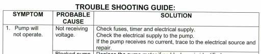
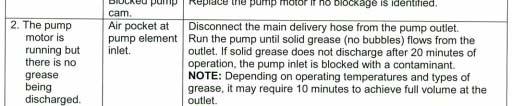
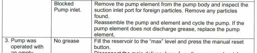
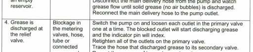
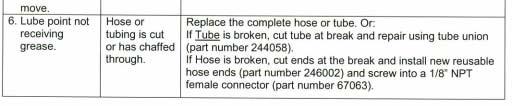
30 Daily Walk-Around Inspection The Lincoln Industrial Quicklub automated lube system components are designed, engineered, manufactured and assembled to the highest quality standards. This lube system requires little maintenance, however, to ensure maximum reliability and to realize maximum service life of all components, it is highly recommended that a daily walk-around inspection be performed. The daily walk-around inspection should include the following: NOTE: Operator to confirm operation of electric pump while machine is in service. Observe lubricant level in reservoir. Fill reservoir if it is low. Inspect the relief valve for excess purge of grease. Refer to the trouble shooting guide on next page. Inspect all valves and lube point connections to verify that no leaks are occurring. Inspect supply/feed lines to insure that no breaks or leaks have occurred. Inspect lube points so that all lube points have a fresh grease appearance. 30
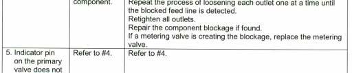
31 Troubleshooting Locating Blockage in Lincoln Quicklub Systems Description In a Lincoln Quicklub Lubrication System, free flow of lubricant from the pump through the transmission system and the bearings is necessary. If any portion of this transmission system (a divider valve, line fitting or any bearing) does not freely accept and pass its portion of the lubricant a blockage has occurred. This blockage will cause a higher than normal pumping pressure to be developed by the pump. Depending on the application or system design, this blockage with its resultant high pump pressure will usually cause a complete loss of lubricant flow into the total system and no bearing will be receiving lubricant. The loss of flow due to a blockage is first indicated with the higher than normal system pressure that is developed by the pump as it attempts to overcome this blockage. This abnormally higher pressure that is a result of a blockage is limited, isolated, and signaled through the use of various performance indicators, reset and relief, incorporated into the system design. Divider Valve A Quicklub divider valve is a proportioning device consisting of a minimum of three pistons. A primary divider valve is the first divider valve downstream from the lube pump. A secondary divider valve is any divider valve receiving lubricant from the primary divider valve. Outlets Each outlet on a Quicklub divider valve dispenses.012 in³ per cycle. If an outlet is plugged, the lubricant will be diverted to the next outlet down allowing proper proportioning of lubricant to all lubrication points. Warning Never block lube outlets numbered one and two. Locating Blockage If a blockage exists in a Quicklub lubrication system it is caused by one of the following reasons: (1) Crushed transmission line in the System. (2) Blocked bearing in the system. (3) Improperly drilled fitting in the system. (4) Blocked divider valve in the system. All servicing and disassembling should be carried out under the cleanest conditions possible. A blockage in a Quicklub system will be indicated by the fault light and by the pump element relief indicator, exhausting lubricant to atmosphere. Before proceeding as outlined, make a visual inspection of the system and check for crushed lines or improper divider valve installation. Verify that each divider valve outlet required to discharge lubricant can do so and that no plugs have been installed in an outlets one and two of any valve. Use Filtered Lubricant Only. 31
32 Note: Dirt and foreign material are the worst enemies of any lubricating system. Procedure 1. Use a manual pump with a gauge. Fill the pump with clean, filtered lubricant common to the system. Connect the manual pump into the inlet of the primary divider valve and slowly operate pump. If system will not cycle freely below 1,500 PSI, see Step With pressure on the primary as outlined in step 1, remove one at a time each supply line (if the supply lines cannot be removed, remove outlet fittings starting from the bottom and working towards the valve inlet) and attempt to operate manual pump after each line is removed. Do not exceed 2,000 PSI. If pressure drops and primary cycles freely after a line is removed then blockage is downstream in the area that is being served from that outlet. See Step 3. If all feed lines are removed and primary will not cycle, blockage is in this divider valve. Note: When a feed line of a blocked area is removed a small shot of trapped lubricant will usually surge out of this outlet as the inlet pressure on the divider valve drops. If testing in Step 2 indicates a blockage in the primary divider valve, this divider valve must be replaced. 3. Testing accomplished in Step 2 has indicated the blockage is downstream of the primary divider valve. Reinstall the feed line into the primary valve and proceed to downstream secondary divider valve and repeat step 2 on the secondary valve. If lubricant can be discharged freely through the secondary valve, the blockage is in the supply line between the primary and the secondary valve. 4. If high pressure exists on one of the secondary outlets, blockage has been located. Look for crushed line, tight bearing, improperly drilled fittings and/or lube inlet port. Correct as necessary. Contamination If dirt, foreign material or any other form of contamination is found as the source of the blockage, clearing the blockage will only temporarily solve contamination blockage problems. The source of the contamination must be eliminated for satisfactory service. The reservoir must be inspected and cleaned if necessary. The reservoir filling method should be reviewed to eliminate any chance of foreign material entering the reservoir during filling. All lubricating systems require filtered lubricant. Grease Separation Blockage If a hard wax or soap like material is found in the valve outlets, grease separation is occurring. This means that the oil is being squeezed from the grease at normal system operating pressure and the grease thickener is being deposited in the divider valve. Cleaning the divider valve will usually result in only temporarily solving the problem. Consult your lubricant supplier for recommendations on alternate lubricants and your local Lincoln Distributor to verify compatibility with centralized lubricating systems 32
33 33
Automated Lubrication System
 Automated Lubrication System Operator s Guide Lexion 700 Series Combine Rev. 1, 7/11, CWA Contents Pages Introduction 3 Component Appendix 4-6 Glossary f Terms 7-8 System Operation 9 Valve Operation 10-11
AGCO Massey Ferguson Combine Models 8780, 9690, Lincoln Automatic Lubrication System Installation Instructions
 AGCO Massey Ferguson Combine Models 8780, 9690, 9790 Lincoln Automatic Lubrication System Installation Instructions System Overview Thank you for purchasing the Quicklub On Board Grease System for your
Automated Lubrication System
 Automated Lubrication System Installation/Operation Manual Case IH Combine Models 2344, 2366, 2377 and 2388 Revised 08-09-06 1 System Overview Thank you for purchasing the Quicklub On Board Grease System
John Deere R Series Sprayer Lubrication System Installation Guide
 John Deere R Series Sprayer Lubrication System Installation Guide 1 Contents Pages Preparation/Installation Overview 3 Introduction 4 Purging Instruction 5 Divider Valve Operation 6 Components Glossary
Automated Lubrication System
 Automated Lubrication System Installation/Operator Instructions John Deere STS Combine Models 9660, 9760, 9860 Dtd.081506 1 System Overview Thank you for purchasing the Quicklub Combine. On Board Grease
Automated Lubrication System
 Automated Lubrication System Installation/Operator Instructions John Deere STS Combine Models 9660, 9760, 9860 Dtd.020405 1 System Overview Thank you for purchasing the Quicklub Combine. On Board Grease
John Deere R4045 Sprayer Wet/Dry Lubrication System Installation Guide
 John Deere R4045 Sprayer Wet/Dry Lubrication System Installation Guide 1 Contents Pages Preparation/Installation Overview 3 Introduction 4 Purging Instruction 5 Divider Valve Operation 6 Components Glossary
Purging Air From Divider Block Lubrication Systems
 FROST ENGINEERING SERVICE Purging Air From Lubrication Systems A D I V I S I O N O F G E C S E Y S A L E S & S E R V I C E DESCRIPTION Divider block lubrication systems operate correctly only when all
Quicklub Lubrication Systems Fittings, Adapters and Accessories
 Divider Valve Mounting Accessories 24646 Valve mounting bracket 5304 4" nylon locknut for valve mounting 247023 Grade 8, 4" valve mounting bolt 239499 Template for divider valve mounting (6, 8, 0 and 2
Lincoln Quicklub centralized and automatic lubrication systems
 Lincoln Quicklub centralized and automatic lubrication systems People, capabilities and systems to save money and increase productivity We re the largest and most successful company in our field because
Quicklub Lubrication Systems Fittings, Adapters and Accessories
 Divider Valve Mounting Accessories 246416 Valve mounting bracket 51304 ¼" nylon locknut for valve mounting 247023 Grade 8, ¼" valve mounting bolt 239499 Template for divider valve mounting (6, 8, 10 and
Owner s and Maintenance Manual for: Lincoln QuickLub Systems
 Owner s and Maintenance Manual for: Lincoln QuickLub Systems Contents: I. Introduction 1. System Operation 2. Components II. Pump Mounting and Wiring 1. Power 2. Testing III. Purging and Testing IV. Programming
Trouble Shooting Manual Progressive Systems
 1 INTRODUCTION The information contained in this manual provides insight in how a progressive grease distribution system works and how to trouble shoot a progressive system. 2 OPERATING PRINCIPLE Any pump
Quicklub Lubrication Systems
 Fittings, Adapters and Accessories Divider Valve Mounting Accessories 246416 Valve mounting bracket 51304 ¼" nylon locknut for valve mounting 247023 Grade 8, ¼" valve mounting bolt 239499 Template for
Lean Lube Valve. Instructions A. Models: page 2. - For oil and grease lubrication -
 Instructions Lean Lube Valve 313721A - For oil and grease lubrication - Models: page 2 4500 psi (31 MPa, 310 bar) Maximum Working Pressure Important Safety Instructions Read all warnings and instructions
A system of lubricant dispensing devices (oil or grease) connected by piping to a central pumping unit that is operated automatically or manually.
 connected by piping to a central pumping unit that is operated automatically or manually.") Air/Oil Systems: A lubrication system in which small measured quantities of oil are introduced into an air/oil mixing device which is connected to a lube line that terminates at a bearing, or other lubrication
Air/Oil Systems: A lubrication system in which small measured quantities of oil are introduced into an air/oil mixing device which is connected to a lube line that terminates at a bearing, or other lubrication
Page 1 of 17. Part# M0200 Rev.11 7/29/2016
 Part# M0200 Rev.11 7/29/2016 This manual contains important information concerning the installation and operation of the product listed above. Read manual thoroughly and keep for future reference INSTRUCTIONS
Centralized & Automated Lubrication Systems. I design Quicklub and other systems to satisfy each customer s unique requirements.
 Quicklub Centralized & Automated Lubrication Systems I design Quicklub and other systems to satisfy each customer s unique requirements. Patrick Sändker, Application Engineer, Lincoln Industrial Systems
ACHL Series Pump. Operation and Maintenance Manual Air Driven, Hand Operated High Pressure Liquid Pump
 ACHL Series Pump Operation and Maintenance Manual Air Driven, Hand Operated High Pressure Liquid Pump Catalog: 02-9245ME February 2013 Model # Serial # Drawing # Order # Mfg. Date Table of Contents page
SOLUTIONS. Airless Spray System. In This Issue: Airless Spray System pg. 2. Improved FlowMaster pg. 5
 THE LATEST PRODUCTS AND NEWS FOR LINCOLN CUSTOMERS SOLUTIONS DECEMBER 2002 VOL. 4, NO. 1 Airless Spray System In This Issue: Airless Spray System pg. 2 Improved FlowMaster pg. 5 MC 2 Progressive High Pressure
INSTALLATION, OPERATION, AND MAINTENANCE MANUAL
 INSTALLATION, OPERATION, AND MAINTENANCE MANUAL MODEL 4D-200 REDUCED PRESSURE PRINCIPLE (RPZ) & MODEL 4D-700 REDUCED PRESSURE DETECTOR ASSEMBLY (RPDA) BACKFLOW PREVENTERS 2 ½ 10 Conbraco Industries Inc.
STREAMLINER M 500 cc Instructions. User Operating Manual
 STREAMLINER M 500 cc Instructions User Operating Manual Lubricator Model Types STREAMLINER M (500cc Grease Lubricator) Before Use Thank you for purchasing the STREAMLINER M 500cc unit, the new electro-mechanical,
Troubleshooting of the LubeTech Grease System
 Troubleshooting of the LubeTech Grease System February 2009 The LubeTech grease system is designed to be a preventative maintenance system that will extend the life of your bearings that are connected
Digitrip Retrofit System for ITE K-3000, K-3000 S, K-4000 and K-4000 S Breakers
 Supersedes IL 33-858-4 Dated 05/02 Digitrip Retrofit System for ITE K-3000, K-3000 S, K-4000 and K-4000 S Breakers Digitrip Retrofit System for ITE K-3000, Digitrip Retrofit System for ITE K-3000, K-3000
MODELS 9917, , 9946P and 9989 High Pressure Lubrigun Series A
 MODELS 9917, 9917-57, 9946P and 9989 Series A NOTE: Pails and Drums shown for illustration only. not included with models. MAR - 2007 Section - A5 Page - 84 DESCRIPTION Models 9917, 9917-57, 9946P, and
Xtreme Air Command. Step 1 Prepare the components. Step 2 Select a mounting location. Parts list
 2549 60 90 400 600 30 200 120 800 psi 1000 kpa PSI 0 150 Xtreme Air Command Installation instructions Congratulations on your purchase of a new Xtreme Air Command kit. This kit was designed to provide
Lubrication Systems. Section 26
 Lubrication Systems Section 26 26-1 INFORMATION - SYSTEMS The Lincoln QuickLub is an automated and centralised lubrication system that can improve productivity and extend the service life of your plant.
MINI WRAP INSTALLATION MANUAL Part # WRAPMHYD[... ]01 WRAPMELE[... ]01 FOR COTTON CLOTH, STAR FOAM or C-CHANNEL FOAM BRUSHES
![MINI WRAP INSTALLATION MANUAL Part # WRAPMHYD[... ]01 WRAPMELE[... ]01 FOR COTTON CLOTH, STAR FOAM or C-CHANNEL FOAM BRUSHES](/thumbs/90/104454538.jpg "MINI WRAP INSTALLATION MANUAL Part # WRAPMHYD[... ]01 WRAPMELE[... ]01 FOR COTTON CLOTH, STAR FOAM or C-CHANNEL FOAM BRUSHES") MINI WRAP INSTALLATION MANUAL Part # WRAPMHYD[..... ]01 WRAPMELE[..... ]01 FOR COTTON CLOTH, STAR FOAM or C-CHANNEL FOAM BRUSHES TABLE OF CONTENTS Equipment Utilities Page: 1 Equipment Specifications Page:
MINI WRAP INSTALLATION MANUAL Part # WRAPMHYD[..... ]01 WRAPMELE[..... ]01 FOR COTTON CLOTH, STAR FOAM or C-CHANNEL FOAM BRUSHES TABLE OF CONTENTS Equipment Utilities Page: 1 Equipment Specifications Page:
QUICKLUB CENTRALIZED & AUTOMATED LUBRICATION SYSTEMS
 QUICKLUB CENTRALIZED & AUTOMATED LUBRICATION SYSTEMS Quicklub Simple, cost-effective lubrication solutions for all of your machinery. People, Capabilities and Systems to Save Money and Increase Productivity
ONBOARD AIR HOOKUP KIT
 ONBOARD AIR HOOKUP KIT PART NO. 20052 (30 amp - 110PSI on, 150PSI off) PART NO. 20053 (30 amp - 85PSI on, 105 PSI off) PART NO. 20055 (30 amp - 90 PSI on, 120 PSI off) IMPORTANT: It is essential that you
Schuyler McElrath Gas Turbine Consultant JASC: Jansen s Aircraft Systems Controls, Inc
 Fuel flexibility and reliability in Combined Cycle gas turbine applications Schuyler McElrath Gas Turbine Consultant JASC: Jansen s Aircraft Systems Controls, Inc schuyler@jasc-controls.com www.jasc-controls.com
Operators Manual TTN LUBRICATOR Series Progressive r#9
 Operators Manual TTN LUBRICATOR Series Progressive 5580 r#9 Contents Precautions & Symbols... Manufacturer s Statement... General... Application... TTN Lubricator at a Glance... Technical Data...4 ISO
OPERATION AND PARTS MANUAL
 OPERATION AND PARTS MANUAL MODEL NUMBER : PART NUMBER : TAP- IN KIT 5100-5151 BAYNE MACHINE WORKS, INC. PHONE: (864) 288-3877 910 FORK SHOALS ROAD TOLL FREE: (800) 535-2671 GREENVILLE S.C., 29605 FAX:
INSTALLATION INSTRUCTIONS
 INSTALLATION INSTRUCTIONS ----1075 North Ave. Sanger, CA 93657-3539 toll free: 800-445-3767 web: www.belltechcorp.com---- 5052 AIR JACK 94-99 DODGE ½ TON RAM C-1500 Congratulations! You were selective
INSTALL MANUAL. FOR ON LINE ORDERING- E Commerce Visit Our Website
 INSTALL MANUAL FOR ON LINE ORDERING- E Commerce Visit Our Website WWW.PRESSUREGUARD.COM Contact Information Technical Support: Chris@pressureguard.com Sales Support: Sales@pressureguard.com By Phone: 615-227-6024
Operating Instructions & Parts Manual
 Hydraulic Air/Manual Bottle Jacks Operating Instructions & Parts Manual Model Number ATD-74 ATD-74 Capacity Ton 0 Ton! U.S. Patent No.'s. 5,34,73-5,946,9 This is the safety alert symbol. It is used to
MultiPort II Lubricator
 MultiPort II Lubricator Mobile, Progressive, Grease General The MultiPort II Lubricator is an electrically driven multiple outlet lubrication unit designed primarily for use with progressive divider valve
OWNER/OPERATOR MANUAL. Airmotor effective dia. in. 2.5
 MODELS 282050, 282716 & 283513 AIR OPERATED CHASSIS PUMP SERIES A OWNER/OPERATOR MANUAL SPECIFICATIONS Airmotor effective dia. in. 2.5 Airinlet Material outlet 1/4 NPTF 1/4 NPTF Liquid to Air Pressure
SERVICE PROCEDURES FOR CLUTCH HYDRAULIC UNITS
 SERVICE PROCEDURES FOR CLUTCH HYDRAULIC UNITS SAFETY PROCEDURES Always follow the vehicle manufacturer's recommended safety procedures in your Shop and Owners Manual. REQUIRED TOOLS Flat blade screwdriver,
ROOTS Meters Series B3 Meter Models 8C175-56M175
 ROOTS Meters Series B3 Meter Models 8C175-56M175 Refer to IOM-B3 for Complete Instructions IS:B3 3.03 RECEIVING, HANDLING AND STORAGE ROOTS rotary positive displacement gas meters are precision measurement
INSTALLATION AND OPERATING
 Publication T5-704, Rev. 4 Dated: November 1, 2006 INSTALLATION AND OPERATING MANUAL T50-P TURBOTWIN Engine Air Starter AN 99-448 TABLE OF CONTENTS Section Subject Page 1.0 General Information. 1 2.0 Orientation
AIR/HYDRAULIC INJECTION GUN MODEL INSTRUCTIONS
 I. OPERATION & DESCRIPTION The Air / Hydraulic Injection Gun is a high-pressure tool that should be used with caution and according to these instructions. IMPORTANT: The Gun is 0,000 psi rated. Do not
Models CHASSIS LUBE ELECTRIC GREASE PUMP Series "C" - 13C MAY FORM Page. Section - Q3
 Models 94422 CHASSIS LUBE ELECTRIC GREASE PUMP Series "C" MAY - 2004 FORM 403467 Section - Q3 Page - 13C 9.00" (229 mm) 13.75" (350 mm) 0.35" (9mm) Mounting Holes 4.76" (121 mm) 9.84" (250 mm) Do not use
NECO Pumping Systems
 INSTALLATION OPERATION & MAINTENANCE INSTRUCTIONS For Your NECO Pumping Systems PACKAGED CIRCULATING SYSTEM THIS COMPLETELY ASSEMBLED, TESTED, PACKAGED CIRCULATING SYSTEM IS OF THE HIGHEST QUALITY AND
Model CHASSIS LUBE ELECTRIC GREASE PUMP Series "C"
 Model 94222 CHASSIS LUBE ELECTRIC GREASE PUMP Series "C" Indicates change MAY - 2004 FORM 403466 Section - Q3 Page - 12B 7.75" (197 mm) 12.6" (321 mm) 0.35" (9 mm) Mounting Holes 4.85" (123 mm) 8.85" (225
Installation Instructions
 TIMES SQUARE Spread Lavatory Faucet with Speed Connect Drain Installation Instructions 8.80 8.8 Congratulations on purchasing your American Standard faucet with Speed Connect drain, a feature found only
Models CHASSIS LUBE ELECTRIC GREASE PUMP Series "C" - Q3. MAY FORM Section
 Models 94822 CHASSIS LUBE ELECTRIC GREASE PUMP Series "C" - Q3 MAY - 2004 FORM 403468 Section Page - 14B 13.00" (330 mm) 17.72" (450 mm).35" (9 mm) Mounting Holes 4.72" (120 mm) 9.84" (250 mm) Figure 1
TECHNICAL DATA. Viking Technical Data may be found on Style: 90 Degree Pattern (inlet to outlet)
") Flow Control 500a DESCRIPTION The Viking 1-1/2 is a quick opening, differential type flood valve with a spring loaded rolling diaphragm clapper. The can be used to facilitate manual or automatic on/off
Flow Control 500a DESCRIPTION The Viking 1-1/2 is a quick opening, differential type flood valve with a spring loaded rolling diaphragm clapper. The can be used to facilitate manual or automatic on/off
INSTALLATION AND OPERATING MANUAL
 Dated: May 10, 2001 INSTALLATION AND OPERATING MANUAL MODEL: T30-Y TURBOTWIN Engine Air Starter From Tech Development Inc AN96-425 6800 Poe Ave. Dayton OH 45414 Tel: (937) 898-9600 Fax: (937) 898-8431
Service Bulletin Published by Sudden Service, Inc.
 Service Bulletin Published by Sudden Service, Inc. Volume 09 / Number 3 / May 15, 2009 Louisville, Mississippi Pre-operational checks of the MM80 Pack-Rat should be performed before each use in order to
Farval. Dualine Installation System Start-Up. Bulletin DL300 BIJUR DELIMON INTERNATIONAL
 Farval Dualine Installation System Start-Up Bulletin DL300 BIJUR DELIMON INTERNATIONAL 2685 Airport Road Kinston, NC 28504 Tel. 800-227-1063 Fax: 252-527-9232 website: www.bijurdelimon.com DC1-1 SECTION
Centralized Lubrication for Commercial Vehicles Drive Productivity Experience Performance
 Centralized Lubrication for Commercial Vehicles Drive Productivity Experience Performance Increase the efficiency of your commercial vehicles. Proper lubrication saves valuable time and makes maintenance
SYSTEM SAVER 318 AIR COMPRESSOR FOR MACK E-TECH AND ASET ENGINES MAINTENANCE MANUAL
 SYSTEM SAVER 318 AIR COMPRESSOR FOR MACK E-TECH AND ASET ENGINES MAINTENANCE MANUAL NON-THROUGH DRIVE THROUGH DRIVE Service Notes About This Manual This manual provides service and repair procedures for
People, Capabilities and Systems to Save Money and Increase Productivity
 People, Capabilities and Systems to Save Money and Increase Productivity We re the largest and most successful company in our field because we continually satisfy our customers with the world s best lubrication
Q= C. v P S Refer to Table 1 for part numbers and shipping weights. Accessories: Table 1: Valve Part Numbers and Specifications
 1 of 9 1. DESCRIPTION The Viking Flow Control Valve is a quick opening, differential diaphragm flood valve with a spring loaded floating clapper. The Flow Control Valve can be used to facilitate manual
Installation Instructions Series Series
 PORTSMOUTH Spread Lavatory Faucet with Speed Connect Drain Congratulations on purchasing your American Standard faucet with Speed Connect drain, a feature found onlyon American Standard faucets. Recommended
Air Actuated Hydraulic Bottle Jacks
 Air Actuated Hydraulic Bottle Jacks Operating Instructions & Parts Manual Model Number Atd-7412 Atd-7420 Capacity 12 Ton 20 Ton Atd Tools Inc. 160 Enterprise Drive, Wentzville MO 63385 Printed in China
DODGE CUMMINS 24V ISB OEM BYPASS LIFT PUMP KIT Installation Instructions Part #
 2/15/2006 2000-2002 Dodge Cummins OEM Bypass Lift Pump Kit # 1050229-1 - 2000-02 DODGE CUMMINS 24V ISB OEM BYPASS LIFT PUMP KIT Installation Instructions Part # 1050229 PLEASE READ ALL INSTRUCTIONS CAREFULLY
Paint/Solvent/Dump Valve and Flow-Through Valve
 Instruction Sheet P/N 08573D Paint/Solvent/Dump Valve and Flow-Through Valve. Description See Figure. The paint/solvent/dump valve is a normally-closed valve that opens to trigger and/or dump coating material.
Lincoln Quicklub System Installation Manual for: CAT M Loaders
 Lincoln Quicklub System Installation Manual for: CAT 966-972M Loaders Contents: I. Introduction 1. System Operation 2. Components II. III. IV. Special Tools System Layout and Design 1. System Drawing 2.
MHH Modular Divider Valves
 Manzel MHH Modular Divider Valves Available Electronic Only Modular, Series-Progressive, Divider Valve Delivers Positive Oil Lubrication for Gas Engines, Compressors and Similar Equipment at Pressures
150 PSI ILLUMINATED DASH PANEL GAUGE KIT
 150 PSI ILLUMINATED DASH PANEL GAUGE KIT PART NO. 10061 (For Use with 20/30 Amp Systems) PART NO. 20062 (For Use with 30/40 Amp Systems) IMPORTANT: It is essential that you and any other operator of this
Installation Instructions
 Spread Lavatory Faucet with the Speed Connect Drain Congratulations on purchasing your American Standard faucet with Speed Connect drain, a feature found only on American Standard faucets. Speed Connect
MOTOR CITY ROCKERZ INSTALLATION MANUAL Part # ROCKRHYD[... ] ROCKRELE[... ] (ALL COLORS)
![MOTOR CITY ROCKERZ INSTALLATION MANUAL Part # ROCKRHYD[... ] ROCKRELE[... ] (ALL COLORS)](/thumbs/89/99803499.jpg "MOTOR CITY ROCKERZ INSTALLATION MANUAL Part # ROCKRHYD[... ] ROCKRELE[... ] (ALL COLORS)") MOTOR CITY ROCKERZ INSTALLATION MANUAL Part # ROCKRHYD[....... ] ROCKRELE[....... ] (ALL COLORS) TABLE OF CONTENTS Equipment Specifications Page: 1 Equipment Features Page: 1 Suggested Tools and Installation
MOTOR CITY ROCKERZ INSTALLATION MANUAL Part # ROCKRHYD[....... ] ROCKRELE[....... ] (ALL COLORS) TABLE OF CONTENTS Equipment Specifications Page: 1 Equipment Features Page: 1 Suggested Tools and Installation
Digitrip Retrofit System for the ITE LG-3000 (Frameless) Circuit Breaker
 Circuit Breaker") IL 33-LGH-1 Digitrip Retrofit System for the ITE LG-3000 (Frameless) Circuit Breaker SAFETY PRECAUTIONS WARNING POWER CIRCUIT BREAKERS ARE EQUIPPED WITH HIGH SPEED, HIGH ENERGY OPERATING MECHANISMS. THE
IL 33-LGH-1 Digitrip Retrofit System for the ITE LG-3000 (Frameless) Circuit Breaker SAFETY PRECAUTIONS WARNING POWER CIRCUIT BREAKERS ARE EQUIPPED WITH HIGH SPEED, HIGH ENERGY OPERATING MECHANISMS. THE
AIR CONTROL ACCESSORY KIT
 RAPID RESPONSE SYSTEM 2283 AIR CONTROL ACCESSORY KIT INSTALLATION INSTRUCTIONS Congratulations on your purchase of a new Air Control Accessory Kit. This kit was designed to provide inflation control of
Installation Instructions
 TROPIC Spread Lavatory Faucet with EverClean Finish & SpeedConnect Drain Installation Instructions 708.80 Congratulations on purchasing your American Standard faucet with EverClean finish and Speed Connect
Bray/ VAAS Slurry Series Knife Gate Valve 760/762/765/766/767/768 Series Operation and Maintenance Manual
 Bray/ VAAS Knife Gate Valve 760/762/765/766/767/768 Series Table of Contents Definition of Terms 1 Safety Instructions 1 Introduction 2 Unpacking 2 Storage 2 Installation 3 Commissioning 3 Cylinder-Operated
advanced FLOW engineering Instruction Manual P/N: Make: Dodge Model: 2500 / 3500 Year: Engine: I-6 5.9L (td)
") advanced FLOW engineering Instruction Manual P/N: 42-22011 DFS780 PRO Make: Dodge Model: 2500 / 3500 Year: 1998.5-2002 Engine: I-6 5.9L (td) 1 Label Qty. Description Part Number A 1 Fuel Manifold Assembly
advanced FLOW engineering Instruction Manual P/N: 42-22011 DFS780 PRO Make: Dodge Model: 2500 / 3500 Year: 1998.5-2002 Engine: I-6 5.9L (td) 1 Label Qty. Description Part Number A 1 Fuel Manifold Assembly
MicroCoat System Operating Manual MC4000 Series MC785M, MC785M-WF Spray Valves
 MicroCoat System Operating Manual MC Series MC785M, MC785M-WF Spray Valves A NORDSON COMPANY Introduction The MicroCoat System provides precise lubrication control for metal stamping operations. The MC
Hydraulic Long Jacks
 Operating Instructions & Parts Manual Hydraulic Long Jacks Model 44915 44930 44940 44980 44981C (Air option) Capacity 1-1/2 Ton 3 Ton 4 Ton 8 Ton 8 Ton Models 44915, 44930, 44940 & 44980 Model 44981C U.S.
HEAVY DUTY ONBOARD AIR SYSTEM PART NO
 IMPORTANT: It is essential that you and any other operator of this product read and understand the contents of this manual before installing and using this product. SAVE THIS MANUAL FOR FUTURE REFERENCE
PRODUCT SAFETY NOTICE
 PRODUCT SAFETY NOTICE Congratulations. This vehicle has been equipped with a Firestone air suspension system. This suspension will enhance the vehicle s handling when loaded, however, the vehicle s performance
Click Here for Printable PDF File. CHAPTER 3 - BASIC INFORMATION for PERFORMING HYDRAULIC SYSTEM MAINTENANCE
 HWH Online Technical School Lesson 1: Introduction to Hydraulics Chapter 3 - "BASIC INFORMATION for PERFORMING HYDRAULIC SYSTEM MAINTENANCE" (Filename: ML57000-012-CH3.DOC Revised: 22APR16) Click Here
GPS AutoSteer System Installation Manual
 GPS AutoSteer System Installation Manual Supported Vehicles Case IH Combines 7010 7120 8010 8120 AFX 8010 9120 PN: 602-0283-01-A LEGAL DISCLAIMER Note: Read and follow ALL instructions in this manual carefully
Operating Instructions & Parts Manual. Air/Manual Hydraulic Bottle Jacks
 J18124-M1_032015 Operating Instructions & Parts Manual Air/Manual Hydraulic Bottle Jacks Model J18124 J18204 Capacity 12 Ton 20 Ton U.S. Patent Nos. 6,012,377-5,946,912! This is the safety alert symbol.
Long Chassis Hydraulic Service Jacks
 Model BH6011 Long Chassis Hydraulic Service Jacks Operating Instructions and Parts Manual Capacity 10 Ton Model BH6011 U.S. Patent No's. 5,946,912 5,341,723! This is the safety alert symbol. It is used
Hydraulic Transmission Jack, Telescopic
 Operating Instructions & Parts Manual Hydraulic Transmission Jack, Telescopic Model 4000 400 (Air Operated) Capacity 000 lbs. 000 lbs. Model 4000 Model 400 U.S. Patent No. 6,02,377! This is the safety
INSTALLATION MANUAL BULLET PROOF OIL COOLER KIT F-SERIES
 INSTALLATION MANUAL BULLET PROOF OIL COOLER KIT 2003-2007 F-SERIES NEAL TECHNOLOGIES, INC. U.S. PATENT 8,375,917; 8,505,512 and OTHER PATENTS PENDING UPDATED 1/8/2018 2014 BULLET PROOF DIESEL BEFORE You
advanced FLOW engineering Instruction Manual P/N: Make: RAM Model: 1500 EcoDiesel Year: Engine: V-6 3.0L (td)
") advanced FLOW engineering Instruction Manual P/N: 42-22041 DFS780 PRO Make: RAM Model: 1500 EcoDiesel Year: 2014-2016 Engine: V-6 3.0L (td) 1 Label Qty. Description Part Number A 1 Fuel Manifold Assembly
advanced FLOW engineering Instruction Manual P/N: 42-22041 DFS780 PRO Make: RAM Model: 1500 EcoDiesel Year: 2014-2016 Engine: V-6 3.0L (td) 1 Label Qty. Description Part Number A 1 Fuel Manifold Assembly
INSTALLATION INSTRUCTIONS
 INSTALLATION INSTRUCTIONS Part# 69-0717 AIR IT UP 4 Tire On Board Installed Air Delivery System with Rear Mounted Controller (Requires External Air Source) For the most up-to-date instructions please visit
Your key to maximum design flexibility with seriesprogressive
 Bulletin 10102 R MSP Modular Divider Valves Your key to maximum design flexibility with seriesprogressive reliability. IDEX CORPORATION LUBRIQUIP, INC., A Unit of IDEX Corporation 1995. All Rights Reserved.
Part# JL AIR IT UP 4 Tire On Board Air Delivery System. (Requires External Air Source)
") Part# 18-1819 JL AIR IT UP 4 Tire On Board Air Delivery System (Requires External Air Source) The most up-to-date instructions always visit www.updownair.com www.updownair.com 833-226-4863 I M P O R T
Part# 18-1819 JL AIR IT UP 4 Tire On Board Air Delivery System (Requires External Air Source) The most up-to-date instructions always visit www.updownair.com www.updownair.com 833-226-4863 I M P O R T
Installation Instructions
 COLONY/COLONY SOFT Bidet Faucet and Transfer Valve with Speed Connect Drain Congratulations on purchasing your American Standard faucet with the Speed Connect drain, a feature found only on American Standard
2 Model 826 Dispensing Valve User Guide
 2 Model 826 Dispensing Valve User Guide About Dymax UV/Visible light-curable adhesives. Systems for light curing, fluid dispensing, and fluid packaging. Dymax manufactures industrial adhesives, light-curable
Assembly Instructions
 Assembly Instructions Part Number Description Model Approx. Assembly Time 99994-049 Cab Enclosure MULE SX 3-4 Hours WARNING Improper installation of this accessory could result in an accident causing serious
Installation Instructions
 BERWICK / BOULEVARD MONOBLOCK LAVATORY FAUCET with Speed Connect Drain Installation Instructions 70.0 7.0 Congratulations on purchasing your American Standard faucet with Speed Connect drain, a feature
Light Duty Electronic Air Command
 2491 PSI BAR Light Duty Electronic Air Command INSTALLATION INSTRUCTIONS Congratulations on your purchase of a Light Duty Electronic Air Command kit. This kit was designed to provide inflation control
OPERATION AND PARTS MANUAL
 OPERATION AND PARTS MANUAL MODEL NUMBER : PART NUMBER : GRL 1110 1900-0540 SERIAL NUMBER : BAYNE MACHINE WORKS, INC. PHONE: 864.288.3877 910 FORK SHOALS ROAD TOLL FREE: 800.535.2671 GREENVILLE SC, 29605
Auto-Flo Panel Reinforcement Automatic Dispensing Valve
 Auto-Flo Panel Reinforcement Automatic Dispensing Valve Customer Product Manual Part NORDSON CORPORATION AMHERST, OHIO USA Nordson Corporation welcomes requests for information, comments and inquiries
THE REVOLUTIONARY P653S ELECTRIC CENTRO-MATIC PUMP
 Lincoln The Industry Leader Since 1910 The Heart of a Centro-Matic Automated Lubrication System The P653S is the central pump station that automatically delivers lubricant through a single supply line
Warning and Safety Precautions
 EXPRESS WARRANTY AND DISCLAIMER OF IMPLIED WARRANTIES Lily Corporation unconditionally guarantees its products to be free of defects in material or workmanship and further warrants that, for a period of
FlowMax Lift Pump Kit
 15 June 2016 (1050316) 2008-2010 Ford 6.4L FlowMax Lift Pump Kit (I-00359) - 1-2008-2010 Ford 6.4L PowerStroke FlowMax Lift Pump Kit Installation Instructions P/N# 1050316 PLEASE READ ALL INSTRUCTIONS
½ DODGE CUMMINS OEM BYPASS LIFT PUMP KIT Installation Instructions Part #
 29 July 2005 2003-04.5 Dodge Cummins OEM Bypass Lift Pump Kit # 1050227-1 - 2003-04½ DODGE CUMMINS OEM BYPASS LIFT PUMP KIT Installation Instructions Part # 1050227 PLEASE READ ALL INSTRUCTIONS CAREFULLY
OPERATION AND PARTS MANUAL
 OPERATION AND PARTS MANUAL MODEL NUMBER : PART NUMBER : Revolution 1999-0500 SERIAL NUMBER : BAYNE MACHINE WORKS, INC. PHONE: 864.288.3877 910 FORK SHOALS ROAD TOLL FREE: 800.535.2671 GREENVILLE SC, 29605
THROUGH-THE-TUBE PLUGGING WITH CPI / PERMA PLUGS
 PAGE 1 OF 13 THROUGH-THE-TUBE PLUGGING WITH CPI / PERMA PLUGS CPI / Perma Plugs are part of the Pop-A-Plug Tube Plugging System. Unlike other tube plug designs, and under the proper conditions, CPI / Perma
Eclipse GEN 2.0 CAFSystem, Model 150-ECL CAFS PTO Kit Installation Instructions
 Eclipse GEN 2.0 CAFSystem, Model 150-ECL CAFS PTO Kit Installation Instructions Read Read through the the safety installation information instructions overhaul carefully instructions before carefully beginning
16000SIII Automatic Grease System
 Manual # 99905495 16000SIII Automatic Grease System Effective 20120716 IOWA MOLD TOOLING CO., INC. PO Box 189 Garner, IA 50438 Tel: 641-923-3711 FAX: 641-923-2424 Website: http://www.imt.com Copyright
MH Modular Divider Valves Product Specs and Ordering. and. Bulletin Revised October 2000
 Bulletin 10103 R and MH Modular Divider Valves Product Specs and Ordering Modular, Series- Progressive, Divider Valve Delivers Positive Oil Lubrication for Gas Engines, Compressors and Similar Equipment
Operation and service manual
 Operation and service manual SKF Multilube SKF Multilube Central lubrication system Table of contents General system description... 1 Safety instructions... 1 General information on centralized lubrication