Technical Manual. Installation Instructions Safety Notices Programming Operation
|
|
|
- Gyles Webb
- 6 years ago
- Views:
Transcription

1 Technical Manual Installation Instructions Safety Notices Programming Operation
2 Congratulations We congratulate you on your purchase of this electronic additive dosing system Electronic Valve Protector Sequential of highest quality and thank you for your trust. Using this dosing system in combination with a suitable valve protection additive can significantly reduce the wear of engine parts. We recommend you read through these operating instructions carefully before putting this device into operation. Please observe all safety notes and all instructions on use, connection and settings. Note All rights reserved. The content of this manual is the property of SI-Elektronik GmbH. Copying or reproduction of this manual or parts of it without the explicit consent of SI-Elektronik GmbH is prohibited. Typographical and printing errors excepted. Subject to technical change. We are not liable for any damages, loss or costs to the buyer or third parties arising out of incorrect operation, accident or improper use, repair or connection. Use only original replacement parts and accessories. We are also not liable for any consequential damages or loss resulting from use of this product. SI-Elektronik GmbH Max-Planck-Straße 5 D Maintal 2
3 Table of Contents Table of Contents...3 Introduction...4 Intended use:...4 Use in LPG driven vehicles...4 How does the Valve Protector work?...5 Basic functions for setting additive dosage calculation LPG valve timing (recommended) Revolution speed Interval...6 Additive feed line: Additive jet M5 including non-return valve Additive shunt including non-return valve...7 Electrically connecting the Valve Protector...10 Establish the following circuit connections:...10 Connection note:...10 Attention:...10 Wiring plan for relay for switching off...12 Installing and bringing the Electronic Valve Protector into operation:...13 Note...15 Quick start instructions Amount setting...16 Safety Notices...17 Technical Data:
4 Introduction Intended use: Valve Protector Sequential is an electronically controlled dosing unit comprising the following components: 1. Additive tank including fill level sensor 2. Electronically controlled dosing module including wiring harness 3. Feed line connections 4. PA hose Check the kit for completeness when unpacking. The intended use is for dosing suitable and approved additives in internal combustion engines. Valve Protector Sequential has been developed in accordance with prevailing safety guidelines and constructed for use in European countries. The electronic additive dosing system Valve Protector Sequential allows volume-controlled or combustion-dependent introduction of additives or lubricants that reduce the wear of engine parts. Use in LPG driven vehicles In vehicles that do not have cylinder heads, valves or valve seats designed for running on LPG, an appropriate valve protection additive must be added into the combustion chamber by a suitable dosing apparatus in order to protect the affected components. Optimal introduction and distribution of the additive is especially critical here. Most additive manufacturers specify the recommended additive dosage in per-mille, as a ratio of the consumed quantity of LPG (observe the additive manufacturer s specifications for this). The most critical factor influencing the additive s effectiveness is the correct additive dosage, which also involves a reliable supply to the relevant engine parts. The necessary dosage for the respective application is set using the software program. The correct dose Example for 1 : If your vehicle consumes 100 litres of LPG over a distance of 1000 km, then the optimum additive admixture dose is 100 ml. That means a distance of 5000 km will require an additive dose of 500 ml. Additive consumption is therefore a linear function of consumed LPG. Additive consumption is therefore also greater in vehicles with higher LPG consumption. This calculation is only provided as an example, and applies only to a dosage of 1. Always observe the additive manufacturer s specific dosing instructions. 4
5 Valve Protector Sequential offers the following performance features: 1. Constant or consumption-dependent additive admixture over your engine s entire power band 2. LPG components do not come in contact with additive 3. No overdosage or underdosage 4. Ideal additive distribution by sequential feed into the combustion chambers 5. Additive tank fill level gauge including LED empty warning lamp 6. Output for safety shutdown of the LPG system when the additive tank is empty 7. Easy installation with a push-fit system 8. Additive consumption only when required 9. Easily refillable additive tank 10. Also ideal for retrofitting 11. All seals in the system made of high-grade FKM 12. Low acquisition cost 13. Also suitable for turbocharged engines and for direct LPG injection 14. Function monitoring by self-diagnosis of all inbuilt components Functional Design How does the Valve Protector Sequential work? The system consists of an additive tank and an additive dosing unit with an inbuilt electronic controller. The additive dose requirement can be calculated either from the LPG jet timings or from the revolution speed: 1. Dosage calculated from LPG valve timings This method achieves the most precise dosing of additive with respect to the amount of fuel consumed. The timing of any one of the LPG jets is measured via the control input of the Valve Protector Module (purple) and multiplied by the given number of cylinders. The longer the opening times of the jets, the more additive will be injected. Since the dosing system starts working only when the LPG system is active, no unnecessary additive is introduced while running on petrol. The microprocessor built into the dosing module adds up the individual timings until the set dosing threshold is reached. Then, an additive burst is triggered and the dosing calculator is reset to zero. Inbuilt electronic micro-magnetic valves distribute the additive sequentially over the individual cylinders. In turbo vehicles, a characteristic curve in the Valve Protector adjusts for the higher system backpressures and the resulting higher LPG quantities at the same injection times. 5
6 2. Dosage calculated from revolution speed In engines without electronic injection, the revolution speed is the best alternative for additive dosage calculation. The speed pulses from an ignition coil or an equivalent sensor are measured via the control input of the Valve Protector Module (purple). The higher the revolution speed, the more additive will be injected. Since the dosing system starts working only when the LPG system is active, no unnecessary additive is introduced while running on petrol. The microprocessor built into the dosing module adds the speed sensor pulses until the set dosing threshold is reached. Then, an additive burst is triggered and the dosing calculator is reset to zero. In turbo vehicles, a characteristic curve in the Valve Protector adjusts for the higher system backpressures and the resulting higher LPG quantities at a higher revolution speed. 3. Dosage calculated by interval With this function, the additive feed is triggered in a fixed timing cycle. The time to the next additive burst can be set within a range of seconds. This mode is intended for machines that operate under constant load and at steady LPG consumption. Accordingly, the additive can also be dosed at a steady rate. The calculated additive dose is distributed evenly over all connected combustion chambers by individual magnetic valves on each cylinder. 6

7 Additive feed line: The additive is fed separately into each cylinder sequentially. This has the major advantage that all cylinders are supplied with the correct quantity of additive. The following feed line connections can be used for feeding in the additive. 1. Feed over M 5 threaded sleeve into the intake tube of each cylinder: 2. Feed over additive shunt into the rubber hose (NW 5-6) after the LPG jet: 3. Feed over additive shunt into the PA hose (6 mm) after the LPG jet (inline): 7


8 The additive tank The additive tank holds about 600 ml of additive and is equipped with a fill level sensor, and gives early warning when additive has to be refilled. The tank is designed to allow easy, safe installation, and guarantees sturdy mounting. The hose connects to a pivoting quick push-on connector on the tank. The printed scale allows easy inspection of the additive dosage. The tank is easy to refill through the large screw cap, even without a funnel. Since the additive tank requires a ventilation opening located at the top of the cap the 600 ml mark should not be exceeded, so that no additive escapes while driving. The dosing unit with sequential distributor The dosing unit is available as 4 and 6 cylinder models, and is fully encased in a compact die-cast aluminium housing, including the controller circuit board. There are no specifications as to where it must be installed. The system monitors all microvalves and the pump for correct function by an inbuilt pressure sensor. The line connections simply push together. 8
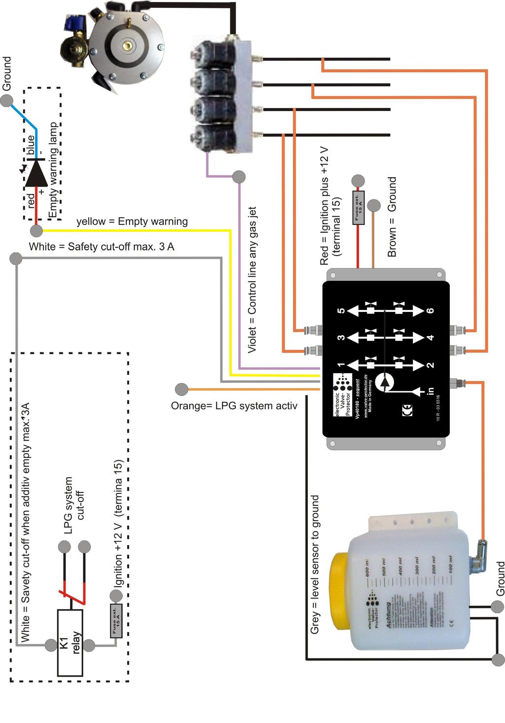
9 Electrical connection The electronic dosing system is simple to connect. Note that the Valve Protector system can draw a current of up to 6 A in bleeding mode. The voltage tap and ground connector must be designed for this power. Establish the following circuit connections: 2-pin plug: 1. Brown Ground ground 2. Red 12 Volt ignition secured (terminal 15) 12 Volt ignition 5-pin plug: 1. Grey Input of additive tank fill level sensor level sensor 2. Yellow LED signal output signal output control lamp 3. Orange 12 Volt during LPG 12 V at LPG on 4. Violet Control line of any signal any LPG injector LPG injector ** 5. White Open collector output output ground at Stop (switched minus max. 3 A)) for system stop ** If you are setting up dosage by revolution speed, then connect this wire to the ignition coil output Connection note: The LED signal lamp for empty or fault warnings connects to the red wire on the yellow line from the 5 pin plug. The blue LED wire is connected to ground. Interpreting the control lamp: OFF - System is ok Slowly blinking (1-second intervals) additive level low (approx. 100 ml remaining) Blinking rapidly (0.2 sec. intervals) additive empty, system has switched off (no additive dosing) Constantly ON - system error service required The additive tank level sensor is connected as follows: Wire 1 (black) to Ground, Wire 2 (black) to the grey wire of the 5-pin plug. The system stop output (white) is a connected ground output and can be loaded up to 3 A. This output can be inverted from the settings menu. It can be used to switch a relay or valve solenoid (such as tank release valve, vaporizer release valve or similar), and prevents LPG operation when the additive tank is empty. The input 12 Volt at LPG on (orange) from the 5- pin plug starts the Valve Protector Module function. Additive is only introduced if this input is active. (The mode can be set from the menu) 9
10 Wiring plan for LPG system cut-off relay upon empty additive tank Basic circuit for cut-off relay (ignition plus terminal 15) (Positive wire for vaporizer valve) Actuating lead white from Valve Protector dosing module max. 3A (Positive output vaporizer valve) Installation and bringing into operation 1. Install the additive tank as vertically upright as possible at an accessible, cool place in the engine bay or car boot. Make sure the ambient temperature does not exceed 80 degrees C. 2. Install the dosing module (in any orientation) at a cool, accessible place in the engine bay. When installing, make sure you can still reach the hose connections. Make sure the ambient temperature does not exceed 80 degrees C. 3. Use the PA hose to connect the tank to the input of the dosing module. Trim the hose to fit without excessive slack between the output of the tank to the input of the module, then plug it in. (Caution: do not kink the hose, and only use a suitable hose cutter to trim it). Once trimmed, the hose must be inserted about 12 mm into the push-fit connection. To remove the hose, press the ring on the quick-release fastener to loosen it and then pull the hose out. 10

 Using the additive hose, connect the push-fit connector on the threaded")
11 4. Additive feed line connections, sequential. There are three additive feed methods to choose from. a. Additive feed into the manifold by M5 threaded sleeve Drill a 4.2 mm hole into the manifold beside the LPG jet. Tap an M5 thread into this hole. Screw in the additive jet, using thread sealant paste. The length of the thread can be sawn down if required. The end of the jet should not touch the wall inside the manifold. (Caution!! No borings are allowed to get into the combustion chamber, otherwise they could cause considerable damage to the engine) Using the additive hose, connect the push-fit connector on the threaded sleeve to the correct output on the sequential module. Repeat this process for all cylinders. b. Additive feed into the LPG injection hose after the LPG jet Cut through the LPG injection hose at a suitable position after the LPG jet. Insert the additive T-piece and secure it using suitable clip collars. Using the additive hose, connect the push-fit connector of the additive shunt to the correct output on the sequential module. Repeat this process for all cylinders. 11
12 c. Additive feed for inline LPG injection with PA hose Cut through the PA hose at a suitable position after the LPG jet. Insert the ends of the LPG PA hose into the connections of the additive T-junction. Using the additive hose, connect the 4 mm push-fit connector of the additive shunt to the correct output on the sequential module. Repeat this process for all cylinders. 5. Now establish all necessary electrical connections. (See wiring plan) 6. Now fill the additive tank with a suitable valve protection additive (max. 600 ml). Check the system for leaks. 7. The system bleeds itself automatically when first put into operation!!! An air-free additive line to the sequential module is extremely important for faultless functioning of the system. If there are any air bubbles in the additive feed line or pump, the necessary system pressure cannot be established and malfunctions can occur. The system therefore bleeds when it detects air bubble formation. Start the engine and let it idle. The system will now try to build up the necessary system pressure. Since there is still no additive in the pressure reservoir, after about 15 seconds, the Valve Protector starts a bleeding process and draws additive. The positive pressure is delivered alternately to valve 1 and 2. The first time the system is operated, and if there are long additive feed lines, it could be necessary to repeat this process by switching the ignition off and on again. Once the system has bled itself and the necessary system pressure has built up, the Valve Protector Sequential operates according to the entered parameters. There should now be no air bubbles left in the additive feed lines from the additive tank to the module. It is normal for air bubbles to form after the distributor module in the direction of the points of introduction, and this is not a fault. Caution: Additives can cause damage to rubber or plastic parts. Immediately rinse off any escaping additive with plenty of water. 12
13 8. Use the programming cable on the dosing module to connect it to the USB port on your laptop or PC system. Switch the ignition on and now start the Valve Protector program. The Connect indicator on the Valve Protector monitor should now display the connection to the dosing module 9. Now set the appropriate parameters for the vehicle in the Valve Protector program. Tips about the correct settings are given in the right field of the program. 10. While the engine is running on LPG, observe the live screen and check that it is functioning correctly. While the vehicle is LPG-fuelled, the injection timing monitor should display the current injection timings of the connected jets. The pump activity monitor should then fill up towards 100 %. When 100 % is reached, an additive dosage is triggered and the pulse monitor reset to 00. An additive dose should be made into the idle LPG mixture every seconds, depending on the engine characteristics. The next activated cylinder will also be displayed. 11. The system is now fully installed and ready for operation. Note The quantity of additive withdrawn should be inspected after about 1000 kilometres have been driven on LPG. Always observe the additive manufacturer s instructions regarding the correct dosage. If the amount of dosed additive is too high or too low, then decrease or increase the value Dosage in the Settings program window. The specified durabilities and applications are only reference values and do not absolve the customer of his responsibility to perform his own tests or evaluation of the suitability for the application. Please note that elastomers have a limited service life, e.g. due to aging. We therefore recommend regular inspection and change intervals. All information provided is correct to the best of our knowledge. We make no guarantee, however, as to the correctness and completeness of this information. 13
14 14

15 Quick start instructions Amount setting Additonal to the PC-Programming The Electronic Valve Protector module is equipped with a touch sensor (chrome ring). This metallic chrome ring reacts to touch by finger just like a button. On the left side wall of the module, an LED is installed, which indicates the various functions with three colours (red-green-yellow) (see the following installation instructions). Step 1: Start the vehicle and activate gas operation. The dosing module is now provided with power and remains in Set-up ready mode (LED lights up yellow) for 30 seconds. Step 2: While the yellow LED is on, touch the metallic chrome ring with your finger until the LED lights up green. Then remove your finger. (Werkseinstellung 4 Zyl.) Step 3: The LED now flashes x times and indicates the set amount of cylinders. You can set between 1 and 16 cylinders. To change the number of cylinders, simply tap on chrome ring with your finger until you have reached the required number or cylinders. The flash display will always show the number of cylinders set. Once level 16 has been reached, counting starts again at 1. (Factory setting 4 cylinders) Step 4: Once you have set the required number of cylinders, hold down your finger on the chrome ring until the LED light is red. You are now in the setting menu for dosage level setting. Step 5: The LED now flashes x times red and displays the set dosage level. There are (Werkseinstellung. Stufe 9) 15 dosage levels and one level for a quick test run. (Attention: Do not run test run excessively as otherwise too much additive is fed-in). Check the guide level table at the end of this page for the correct dosage level for your vehicle. (Factory setting level 9) To change the dosage level simply tap on to the chrome ring with your finger until the required dosage level is reached. The flash display always shows the set dosage level. After level 16, counting starts again at level 1. Step 6: Once you have reached the desired dosage level, (see required number of flashes), touch the tube connection until the LED light is yellow. For venting of the module the pump can switch on or off by pressing the chrome ring. Step 7: Once you have reached the desired dosage level, (see required number of flashes), touch the chrome ring until the LED light is green. The settings are now stored and the module is in operation mode. The module remains in set-up ready mode (LED yellow) following each restart. If during this phase, the chrome ring is not touched, the module automatically changes into working mode (LED green) after 30 seconds. The setting Table is only a guide! The correct dosage must be checked after each installation and adjusted if required. Display of LED built-in module LED light is green: System has operating voltage but is not receiving control impulses from the gas injector. LED flashes green: System has operating voltage and is receiving control impulses from the gas injector (operating mode) LED slowly flashes red (every second): no input from level sensor into additive tank LED quickly flashes red (every 0.25 sec.): additive depleted LED flashes yellow (every 0.5 sec.): additive is being injected Display of LED to be installed in passenger area LED flashes 3 times for operation control. LED flashes slowly (every second): LED flashes quickly (every 0.25 sec.): power on control remaining additive level reserve approx. 100 ml additive depleted. Guide level table for base amount setting per Cylinder Level Cylinder capacity KW Test Cylinder capacity PS Test 15
16 Safety Notices Intended use: Valve Protector is an electronically controlled dosing unit comprising the following components: 1. Additive tank, 2. Electronically controlled dosing module, 3. Feed line connection, 4. PA hose The intended use is for dosing suitable and approved additives in internal combustion engines. Valve Protector has been developed and constructed in accordance with prevailing safety guidelines. It may only be used under the following conditions: 1. In technically faultless condition 2. After careful leak testing 3. Having been installed and brought into operation by a skilled professional 4. Used only for the intended purpose 5. Failure to observe the safety notices can lead to personal injury and material damage 6. Electrical lines and additive lines must always be laid in such a way as to rule out damage and chafing 7. Observe the additive manufacturer s safety guidelines 8. Compatibility between the additive and the components through which it flows has been checked and confirmed 9. Check for correct dosage at regular intervals 10. In the case of over/underdosage, have the system checked in an authorized service centre. 11. Driving with incorrect dosages can cause damage to your engine and/or exhaust system. 12. Rinse off any spilt additive with plenty of water 13. Refill the additive tank level when it gets low 14. Do not fill above the fill line 15. Never mix different additives 16. Use only approved and authorized additives 17. Using unauthorized additives can forfeit your operating licence 18. Use only original replacement parts 19. The specified durabilities and applications are only reference values and do not absolve the customer of his responsibility to perform his own tests or evaluation of the suitability for the application. Please note that elastomers have a limited service life, e.g. due to aging. We therefore recommend regular inspection and change intervals. All information provided is correct to the best of our knowledge. We make no guarantee, however, as to the correctness and completeness of this information. 20. The warranty period is 24 months from the date of purchase (against presentation of the sales slip or invoice). The warranty becomes void in the case of improper use of the device, use outside the technical specifications, use of an unapproved additive, improper operation or unauthorized interference. We are not liable for any damage resulting from these cases. The exemption from liability also extends to all services performed by third parties that have not been ordered in writing by us. 16
17 Technical Data: Power supply: Current draw: Pump pressure, max.: Pump volume/stroke: Max. power: Weight: Dimensions L/W/H: Device installation orientation: Temperature range: Protection class: Sealing materials: 12V DC (10V 15V) Idle 30 ma, Pump stroke up to 6 A 5 BAR 50 μl additive 180 ml/h 1,250 g 145 mm x 95 mm x 56 mm Any -20/+85 C IP54 FKM (Viton) / Elastomer with high temperature and weathering resistance. Suitable for many acids, bases, fuels and oils (including synthetic). EC Declaration of Conformity pursuant to Annex I to the EC Directive on Electromagnetic Compatibility 2004/108/EC SI-Elektronik GmbH declares that Product name: Valve Protector Sequential Type: VP40127-S Year of manufacture: 2009 conforms to the regulations of the abovementioned EC Guidelines. 17
Instruction of connection and programming of the VECTOR controller
 Instruction of connection and programming of the VECTOR controller 1. Connection of wiring 1.1.VECTOR Connection diagram Fig. 1 VECTOR Diagram of connection to the vehicle wiring. 1.2.Connection of wiring
LAMBDA SENSOR CONTROLLER
 LAMBDA SENSOR CONTROLLER INSTALLATION & PROGRAMMING MANUAL version : V1.77 -V1.79 Manufacturer: AC Spółka Akcyjna. 15-182 Białystok, ul. 27 Lipca 64, Poland tel. +48 85 7438148, fax +48 85 653 8649 www.ac.com.pl,
Timing is everything with internal combustion engines By: Bernie Thompson
 Timing is everything with internal combustion engines By: Bernie Thompson As one goes through life, it is said that timing is everything. In the case of the internal combustion engine, this could not be
VS403 INSTRUCTIONS FOR: VACUUM AND PRESSURE TEST / BRAKE BLEEDING UNIT MODEL: SAFETY INSTRUCTIONS INTRODUCTION & CONTENTS. fig.1
 INSTRUCTIONS FOR: VACUUM AND PRESSURE TEST / BRAKE BLEEDING UNIT MODEL: VS403 Thank you for purchasing a Sealey product. Manufactured to a high standard this product will, if used according to these instructions
EVAP system, servicing
 Page 1 of 65 20-130 EVAP system, servicing EVAP system components 1 - Cap nut 10 Nm 2 - Cover 3 - Stud For EVAP canister 15 Nm 4 - Sealing piece 5 - Bleed line To EVAP canister purge regulator valve -
Operation and service manual
 Operation and service manual SKF Multilube SKF Multilube Central lubrication system Table of contents General system description... 1 Safety instructions... 1 General information on centralized lubrication
INSTALLATION INSTRUCTIONS. Revision 3.1.1
 INSTALLATION INSTRUCTIONS Revision 3.1.1 Table of Contents INTRODUCTION... 4 INSTALLATION OVERVIEW... 5 Included Parts... 6 DEVICE WIRING... 7 Required Parts... 7 Guidelines... 7 Wiring Diagram... 8 Compatible
ENGLISH SAFETY INSTRUCTIONS. Recommendations for safe operation. Operator safety. General warnings
 Safety and use instructions LifeSpeed iq TM - 3-phase chargers ENGLISH SAFETY INSTRUCTIONS GOALS OF THIS MANUAL This manual is aimed at any authorized personnel wanting to use a 3-phase LifeSpeed iq TM
Preparing and programming of ESGI 2 LPG supply system manual
 Preparing and programming of ESGI 2 LPG supply system manual Part II Instruction of preparing and programming the ESGI system 1 Technical data of the central unit Vs Power supply voltage 0...16V V i_an
new products R02 W02 STAG-4 QBOX PLUS 200 GoFast
 new products 2014 R02 W02 STAG-4 QBOX PLUS 200 GoFast STAG 200 GoFast STAG easy fast intuitive installation The key idea of the controller is an intuitive system focused on fast and easy installation,
VAPORIX-PCM. Technical Documentation. Corrective control module for connection to VAPORIX-Control. Version: 3 Edition: Art.
 Technical Documentation VAPORIX-PCM Corrective control module for connection to VAPORIX-Control Version: 3 Edition: 2016-08 Art. No: 350102 FAFNIR GmbH Schnackenburgallee 149 c 22525 Hamburg, Germany Tel.:
Automotive Application ET01 Software Revision A 12/06
 Automotive Application ET01 Software Revision A 12/06 INTRODUCTION... 2 FUNCTIONAL DESCRIPTION... 3 INSTALLATION... 4 COMPONENT PLACEMENT... 4 PLUMBING AND WIRING... 5 MSBC OPERATION (ET-01)... 14 TIMED
MAKE OF AUTOMOBILE: ENGINE SET NUMBER 345/ NUMBER : 076/ DATE : VERSION NR : B
 MAKE OF AUTOMOBILE: TYPE: LOGAN PISTON DISPLACEMENT: 1600 NUMBER OF VALVES: 8 ENGINE NUMBER: K7M 710 TRANSMISSION TYPE ( MT / AT ) MT VEHICLE CATEGORIES M or N ( M ) TYPE VSI INJECTOR ( NUMBER + COLOR
Operating and Installation Instructions
 Model Number 40401-c (-sp) Electronic Fuel Pump Operating and Installation Instructions This Product is Patent Pending. Application available upon request CAUTION! This product is to be installed only
Screw-type and measuring capsule heat meter with IrDA interface and an interface for retrofitting external modules or with integrated communication.
 Data sheet DST2-QHEA-GB0 HMx / 11.05.2016 - V 1.0 Heat meter Q heat 5 Screw-type and measuring capsule heat meter with IrDA interface and an interface for retrofitting external modules or with integrated
ECONOMISER SERIES E2T USER MANUAL
 TURBO S.R.L. Electronic Control Systems for Dust Collectors e-mail: info@turbocontrols.it web: www.turbocontrols.it TEL. ++39 (0)362 574024 FAX ++39 (0)362 574092 ECONOMISER SERIES E2T USER MANUAL 24/06/2014
Intake manifold change-over
 Page 1 of 10 24-67 Intake manifold change-over This test should only be performed if there is a performance deficiency. The intake manifold switches from the long intake path to the short one at approx.
CAUTION: CAREFULLY READ INSTRUCTIONS BEFORE PROCEEDING
 Daytona Sensors LLC Engine Controls and Instrumentation Systems Installation Instructions for Wide-Band Exhaust Gas Oxygen Sensor Interface CAUTION: CAREFULLY READ INSTRUCTIONS BEFORE PROCEEDING OVERVIEW
Prins autogassystemen b.v. Veldhoven
 Prins autogassystemen b.v. Veldhoven MOUNTING INSTRUCTION ENGINE CONVERSION SET MAKE OF AUTOMOBILE: TYPE: ASTRA PISTON DISPLACEMENT: 2000 cc MT NUMBER OF VALVES: 16V ENGINE NUMBER: X20XEV INJECTION SYSTEM:
SAFET Y PRODUCTS. TT-Series Safety Edge Product Manual
 SAFET Y PRODUCTS TT-Series Safety Edge Product Manual 2TLC010046M0201_B ORIGINAL INSTRUCTION S Read and understand this document Please read and understand this document before using the products. Please
Level Measuring Sensor for Diesel Fuel Tanks
 Installation and Operating Manual Level Measuring Sensor for Diesel Fuel Tanks Executions with switchable output voltage signal: 0-2.3 V and industrial standard signal 0-10 V: Tank Sensor Diesel 010-250
Original Language Version VS4021 Issue: 1-08/06/12
 1. safety instructions Keep this product in good working order and condition, take immediate action to repair or replace damaged parts. Use approved parts only. Unapproved parts will invalidate the warranty.
Important instructions
 Operation manual Please read this manual, before starting the unit. It contains important notes on commissioning and handling. Keep these instructions for future reference. Be careful even if you pass
CAUTION: CAREFULLY READ INSTRUCTIONS BEFORE PROCEEDING
 Daytona Sensors LLC Engine Controls and Instrumentation Systems Installation Instructions for WEGO II Wide-Band Exhaust Gas Oxygen Sensor Interface Methanol Version CAUTION: CAREFULLY READ INSTRUCTIONS
Error codes Diagnostic plug Read-out Reset Signal Error codes
 Error codes Diagnostic plug Diagnostic plug: 1 = Datalink LED tester (FEN) 3 = activation error codes (TEN) 4 = positive battery terminal (+B) 5 = ground Read-out -Connect LED tester to positive battery
Mounting and Operating Instructions EB 3913 EN. Electropneumatic Converters i/p Converter Type
 Electropneumatic Converters i/p Converter Type 3913-0001 Fig. 1 Type 3913-0001 Electropneumatic Converter with pressure gauge and bracket Mounting and Operating Instructions EB 3913 EN Edition August 2011
Compact Heat Meters. Features. -A Pulsed output. -B M-Bus output. Accessories. UK Sales Tel: International Tel:
 Compact Heat Meters Features Compact design Simple operation Pulsed output Measures heating or cooling Specification Product Codes Water Meter Temp. range 10 to 90 C Nominal pressure 16bar Installation
MAKE OF AUTOMOBILE: PISTON DISPLACEMENT: 1600 NUMBER OF VALVES: 16
 MAKE OF AUTOMOBILE: TYPE: MERIVA PISTON DISPLACEMENT: 1600 NUMBER OF VALVES: 16 ENGINE NUMBER: Z16XEP TRANSMISSION TYPE ( MT / AT ) MT VEHICLE TYPE M TYPE VSI INJECTOR ( NUMBER + COLOR ) 180/30430 ORANGE
Engine mechanics. Crankcase ventilation outlet
 Engine mechanics Crankcase ventilation outlet The gases are drawn out of the crankcase by the vacuum in the intake manifold. The oil is separated from the gases in the labyrinth and in the cyclone oil
Innovative Racing Electronics
 MPS Fast FI Mixture Control Installation Instructions The MPS Fast FI Mixture Control P/N 1-0337 is a simple means to adjust the fuel curves on your fuel-injected motorcycle. This allows for tuning after
INSTRUCTIONS FOR: VACUUM TESTER AND BRAKE BLEEDING KIT
 INSTRUCTIONS FOR: VACUUM TESTER AND BRAKE BLEEDING KIT MODEL: VS402 Thank you for purchasing a Sealey product. Manufactured to a high standard this product will, if used according to these instructions
BASIC BRAKE SYSTEM GROUP 35A 35A-1 CONTENTS GENERAL DESCRIPTION... 35A-3 BASIC BRAKE SYSTEM DIAGNOSIS 35A-6
 35A-1 GROUP 35A BASIC BRAKE SYSTEM CONTENTS GENERAL DESCRIPTION......... 35A-3 DIAGNOSIS 35A-6 INTRODUCTION..................... 35A-6 DIAGNOSTIC TROUBLESHOOTING STRATEGY......................... 35A-6
LUCAS ACE - System Overview
 LUCAS ACE - System Overview The Active Corner Enhancement system manufactured by Rover Group Lucas appears to have been produced specifically for the Land Rover Discovery series II to address the poor
Features: Enhanced throttle response, excellent acceleration, linearity and driveability
 120A/150A ESC X-Car 120A/150A Series Sensored/Sensorless Brushless ESC for 1:8 scale Car or Truck Thank you for purchasing the X-Car Brushless Electronic Speed Controller (ESC). The X-Car 1:8 Scale 120A/150A
AUTOMATIC STANDBY ACTIVATION. Operation Manual
 AUTOMATIC STANDBY ACTIVATION Operation Manual ATTENTION! Prior to use this unit ple carefully read the Operation Manual 1. INTRODUCTION 1.1 The present Operation Manual applies to study automatic standby
BS5582 VACUUM PUMP AND BRAKE BLEEDER KIT Instructions
 RELEVANT PRODUCTS OF BRAKE SYSTEM SERVICE Motorcycle Service Tools BS5630 Brake Fluid Tester BS0245 BS5800 Brake Fluid Condition Tester Detaching Tool Motorcycle Service Tools BS9870 30mm Disc Brake Spreader
Datasheet PDCSY-MW-CHM. Technical Overview. Features. Product warranty and total quality commitment. General Information.
 Datasheet Compact Heat Meters Technical Overview Heat energy is calculated by using a matched pair of high accuracy sensors to measure the difference between the forward and flow temperatures. The amount
User Manual. Digital Energy Uninterruptible Power Supply ML Series UPS VA. GE Digital Energy Power Quality. GE imagination at work
 GE Digital Energy Power Quality User Manual Digital Energy Uninterruptible Power Supply ML Series UPS 350-500-700-1000 VA GE Consumer & Industrial SA General Electric Company CH 6595 Riazzino (Locarno)
Model 1:8 Beast-ZTWSS120A 1:8 Beast-ZTWSS150A. PN#Model Cont.Current 120A 150A. Burst Current 760A 1080A
 Alien Power System BEAST Series Sensored/Sensorless Brushless ESC for 1:8 scale Car or Truck Thank you for purchasing the Alien Power System Brushless Electronic Speed Controller (ESC). The Alien Power
MB A 12V/24V DC PROGRAMMABLE DUAL BATTERY ISOLATOR
 MB-3688 120A 12V/24V DC PROGRAMMABLE DUAL BATTERY ISOLATOR User Manual Warning and Precautions MB-3688 is built with corrosion resistant material and the main electronic assembly is well sealed inside
Controller Ground (dual black 12awg) should be connected to chassis ground as close as possible to the battery.
 should be connected to chassis ground as close as possible to the battery.") 1. Overview The Maximizer 4 progressive nitrous controller operates one or two separate stages of nitrous based on either time, RPM, MPH, throttle percentage or boost pressure. Whether your engine is naturally
1. Overview The Maximizer 4 progressive nitrous controller operates one or two separate stages of nitrous based on either time, RPM, MPH, throttle percentage or boost pressure. Whether your engine is naturally
Smart Battery Charger
 BATTERY CHARGER Smart Battery Charger Model No. WSC-1215 (SB) WSC-1230 (SB) WSC-2408 WSC-2415 Manual Please read this manual carefully before installing and starting up this device. Figure 1 WSC-1215SB
Motronic injection system,
 Page 1 of 78 24-1 Motronic injection system, servicing Safety precautions If special testing equipment is required during road test, note the following: WARNING! Scan tools and testing devices must always
Instruction of connection and programming of the OSCAR-N controller
 Instruction of connection and programming of the OSCAR-N controller Table of content Paragraph Description Page 1 Installation of OSCAR-N sequential gas injection system 2 1.1 OSCAR-N sequential gas injection
SBS Manual for the specialised craftsman. Filling and flushing station. Connection Operation. en Manual
 SBS 2000 Filling and flushing station Manual for the specialised craftsman Connection Operation Thank you for buying this RESOL product. Please read this manual carefully to get the best performance from
Smart 110 with built-in flashlight for 6 240Ah lead-acid batteries
 USER GUIDE Battery Charger Smart 110 with built-in flashlight for 6 240Ah lead-acid batteries Please read this user guide carefully before using the charger Use protective eyewear when handling batteries
MAKE OF AUTOMOBILE: TYPE: V 70 PISTON DISPLACEMENT: 2521 NUMBER OF VALVES:
 MAKE OF AUTOMOBILE: TYPE: V 70 PISTON DISPLACEMENT: 2521 NUMBER OF VALVES: 20V ENGINE NUMBER: B5254T TRANSMISSION TYPE ( MT / AT ) AT VEHICLE CATEGORIES M or N PASSENGER CAR ( M ) TYPE VSI INJECTOR (COLOUR
HGM1780 AUTOMATIC GENERATOR MODULE CONTENT 1. SUMMARY PERFORMANCE AND CHARACTERISTICS SPECIFICATION OPERATION...
 CONTENT 1. SUMMARY...4 2. PERFORMANCE AND CHARACTERISTICS...4 3. SPECIFICATION...5 4. OPERATION...6 4.1. DISPLAY PANEL...6 4.2. LCD ICON INSTRUCTION...7 4.3. DISPLAY INSTRUCTIONS...7 4.4. DISPLAY DESCRIPTION...8
LPG STARTBOX. Instruction Manual. Rempel Power Systems GmbH
 LPG STARTBOX Rempel Power Systems GmbH 2014-10-24 Content Installation Guidelines... 2 Layout... 2 Getting started (Learning mode)... 3 Operating mode... 5 Switch positions... 6 Programming mode (Firmware
EN Operating manual. Motorised zone valve. Three-way, 22 mm & 28 mm 3PV2, 3PV8 & VRMH3
 EN Operating manual Motorised zone valve Three-way, 22 mm & 28 mm 3PV2, 3PV8 & VRMH3 This manual ensures safe and efficient use of the 3PV2 or 3PV8 force-actuated three-way valve with spring-loaded return
User Manual Digital Energy Uninterruptible Power Supply ML Series UPS VA GE Digital Energy Power Quality
 GE Digital Energy Power Quality User Manual Digital Energy Uninterruptible Power Supply ML Series UPS 350-500-700-1000 VA GE imagination at work GB User Manual Digital Energy Uninterruptible Power Supply
Internal MAP Water/Methanol Injection Controller ,
 Internal MAP Water/Methanol Injection Controller 30-3304, 30-3306 WARNING: Improper installation and/or adjustment of this product can result in major engine/vehicle damage! Use of this injection system
MAKE OF AUTOMOBILE: MODEL YEAR: 2007 SYSTEM APPROVAL NUMBER ( R115 ) VSI-LPG 10 ENGINE SET NUMBER 364/
 VSI-LPG 10 ENGINE SET NUMBER 364/") MAKE OF AUTOMOBILE: TYPE: FABIA PISTON DISPLACEMENT: 1400 NUMBER OF VALVES: 16 ENGINE NUMBER: BUD TRANSMISSION TYPE ( MT / AT ) MT VEHICLE CATEGORIES M or N M TYPE VSI INJECTOR ( NUMBER + COLOR ) 180/30410
MAKE OF AUTOMOBILE: TYPE: FABIA PISTON DISPLACEMENT: 1400 NUMBER OF VALVES: 16 ENGINE NUMBER: BUD TRANSMISSION TYPE ( MT / AT ) MT VEHICLE CATEGORIES M or N M TYPE VSI INJECTOR ( NUMBER + COLOR ) 180/30410
INSTALLATION INSTRUCTIONS: Viewline 85 mm
 1-10 1 Safety information The product was developed, manufactured and inspected according to the basic safety requirements of EC Guidelines and state-of-the-art technology. The unit is designed for use
HV-Angle Valve (Series 264) HV-InlineValve (Series 265) with electromagnetic actuator single acting with closing spring (NC)
 HV-InlineValve (Series 265) with electromagnetic actuator single acting with closing spring (NC)") HV-Angle Valve (Series 264) HV-InlineValve (Series 265) with electromagnetic actuator single acting with closing spring (NC) This manual is valid for the valve ordering number(s): 26... 26428 -K A 61 A..
HV-Angle Valve (Series 264) HV-InlineValve (Series 265) with electromagnetic actuator single acting with closing spring (NC) This manual is valid for the valve ordering number(s): 26... 26428 -K A 61 A..
C FORD F250 / F L POWERSTROKE DIESEL WITH AUTOMATIC TRANSMISSIONS ONLY
 EXHAUST BRAKES C40019 1999-2003 FORD F250 / F350 7.3L POWERSTROKE DIESEL WITH AUTOMATIC TRANSMISSIONS ONLY Getting Started Thank you and congratulations on your purchase of a Pacbrake exhaust retarder.
MULTIPOINT FUEL INJECTION (MPI) <4G9>
 <4G9>") MULTIPOINT FUEL INJECTION (MPI) 13C-1 MULTIPOINT FUEL INJECTION (MPI) CONTENTS GENERAL................................. 2 Outline of Changes............................ 2 GENERAL INFORMATION...................
MULTIPOINT FUEL INJECTION (MPI) 13C-1 MULTIPOINT FUEL INJECTION (MPI) CONTENTS GENERAL................................. 2 Outline of Changes............................ 2 GENERAL INFORMATION...................
16A. STARTING - CHARGING Starter: Removal - Refitting REFITTING 16A-11 K4M II - REMOVAL OPERATION III - FINAL OPERATION
 STARTING - CHARGING Starter: Removal - Refitting 16A K4M II - REMOVAL OPERATION III - FINAL OPERATION JR5 a Clip: -the gearbox control cable sleeve stops on the gearbox, - the control cables onto the gearbox.
Covers All 430, 440, 441 and CJ Series Advanced Security Systems.
 INSTALL GUIDE Covers All 430, 440, 441 and CJ Series Advanced Security Systems www.ultrastarters.com Technical Support: 866-698-5872 ext 0 support@ultrastarters.com FCC/ID Notice This device complies with
HGM1770 Automatic Generator Control Module OPERATING MANUAL Smartgen Electronic
 HGM1770 Automatic Generator Control Module OPERATING MANUAL Smartgen Electronic CONTENT 1. SUMMARY... 4 2. PERFORMANCE AND CHARACTERISTICS... 4 3. SPECIFICATIONS... 5 4. OPERATION... 6 5. PROTECTION...
GROUP 35A 35A-1 CONTENTS GENERAL DESCRIPTION... 35A-3 BASIC BRAKE SYSTEM DIAGNOSIS 35A-6 HYDRAULIC BRAKE BOOSTER (HBB) DIAGNOSIS...
 DIAGNOSIS...") 35A-1 GROUP 35A CONTENTS GENERAL DESCRIPTION......... 35A-3 DIAGNOSIS 35A-6 INTRODUCTION..................... 35A-6 DIAGNOSTIC TROUBLESHOOTING STRATEGY......................... 35A-6 SYMPTOM CHART...................
35A-1 GROUP 35A CONTENTS GENERAL DESCRIPTION......... 35A-3 DIAGNOSIS 35A-6 INTRODUCTION..................... 35A-6 DIAGNOSTIC TROUBLESHOOTING STRATEGY......................... 35A-6 SYMPTOM CHART...................
MAXIMIZER-II Progressive Nitrous Controller INSTALLATION AND USER MANUAL. MAXIMIZER-II rev A
 MAXIMIZER-II Progressive Nitrous Controller INSTALLATION AND USER MANUAL i Table of Contents Page 1. Installation Overview...1 1.1 MAXIMIZER-II Power Input...1 1.2 SOLENOID DRIVER Ground...1 1.3 Arming
Safety instructions. Always... Never... Fire hazard! Dear customer,
 Dear customer, Safety instructions Danger can occur when working with this punch driver due to improper handling and/or poor maintenance, which may damage the device and cause severe physical injuries.
Setup and Configuration Guide Universal Switch Interface
 Table of Contents J1939 inmotion Cell Setup and Configuration Guide Universal Switch Interface Overview... 2 Warnings... 3 J1939 inmotion Cell Technical Details... 4 inmotion Cell Installation Steps...
PLEASE READ BEFORE CALLING OR RETURNING PRODUCT. EXTREMELY IMPORTANT!!!
 Thank you for your purchase of WeaponX Smart Direct Fire Ignition Coil System for your vehicle. The following are the instruction manuals for your ignition system kit. Please read carefully and enjoy your
MAKE OF AUTOMOBILE: PISTON DISPLACEMENT: NUMBER OF VALVES: ENGINE NUMBER: TRANSMISSION TYPE ( MT / AT ) VEHICLE CATEGORIES M or N PERSONEN AUTO ( M )
 VEHICLE CATEGORIES M or N PERSONEN AUTO ( M )") MAKE OF AUTOMOBILE: TYPE: WRANGLER PISTON DISPLACEMENT: 4000 cc NUMBER OF VALVES: 12 v ENGINE NUMBER: M3 TJ TRANSMISSION TYPE ( MT / AT ) MT VEHICLE CATEGORIES M or N PERSONEN AUTO ( M ) TYPE VSI INJECTOR
MAKE OF AUTOMOBILE: TYPE: WRANGLER PISTON DISPLACEMENT: 4000 cc NUMBER OF VALVES: 12 v ENGINE NUMBER: M3 TJ TRANSMISSION TYPE ( MT / AT ) MT VEHICLE CATEGORIES M or N PERSONEN AUTO ( M ) TYPE VSI INJECTOR
Thank you for your purchase Off-ROad NOtice: PROduct WaRNiNgs:
 Thank you for your purchase. Please, read the instructions and watch the video before installing the JMS Progressive N20 Controller. Configuration and installation videos are available online: www.jms-nos.com.
Common rail injection system
 Common rail injection system Pressure limiting valve The pressure limiting valve is located directly on the high-pressure fuel rail. Its function is to limit maximum pressure in the high-pressure fuel
INSTALLATION INSTRUCTIONS: Viewline 85 mm
 1-10 1 Safety information The product was developed, manufactured and inspected according to the basic safety requirements of EC Guidelines and state-of-the-art technology. The unit is designed for use
MONO - MOTRONIC 0309 En
 02.1992 MONO - MOTRONIC 0309 En Published by: Robert Bosch GmbH Division KH After-Sales-Service Department for Training and Technology (KH/VSK) Please direct questions and comments concerning the contents
Diesel Engine Shutdown System
 Diesel Engine Shutdown System Models CSX-300, 310 CSX-301, 311 Typical applications Marine engine safety Petrochemical industry safety Vacuum trucks Cranes - both engines Land drilling rigs Offshore equipment
Tips & Technology For Bosch business partners
 Tips & Technology For Bosch business partners Current topics for successful workshops No. 09/2010 Gasoline injection Invented for life Engine speed measurement in exhaust emission testing The complete
MULTI FUNCTIONAL COUNT CHECKER MODEL Poka Patrol CNA-4mk3
 MULTI FUNCTIONAL COUNT CHECKER MODEL Poka Patrol CNA-4mk3 OPERATING INSTRUCTION Poka Patrol CNA-4mk3 Poka Patrol CNA-4mk3 To use this product properly and safely, please read this manual carefully before
Mallory HyFire Electronic Ignition Control
 Mallory HyFire Electronic Ignition Control PN 690 Parts Included: 1 - Ignition 1 - Harness, Mag Pickup 1-18" Ground Wire 1-100V/1A Diode 4 - Mounting Screws WARNING: During installation, disconnect the
Injection Oilers, Micro Pumps
 Injection Oilers, Micro Pumps 1-5012-4-US for minimal quantity metering Magnetic piston pump Injection oiler Micropump Grease metering P Metering pumps deliver and meter out lubricants. This piston pumps
USER GUIDE 12 V Lead acid batteries Ah
 USER GUIDE 12 V Lead acid batteries 1-150 Ah GB 1 Thank you for choosing this charger from Exide Technologies Your new battery charger will enable you to keep your battery fully charged and will optimize
INSTALLATION GUIDE Table of Contents
 CT-3100 Automatic transmission remote engine starter systems. What s included..2 INSTALLATION GUIDE Table of Contents Door lock toggle mode..... 4 Notice...2 Installation points to remember. 2 Features..2
Installation & Calibration
 Installation & Calibration ED2-AT Series SkidWeigh System Lift Truck On-board Check Weighing With Accumulative Load Weight Total ED2-AT Series SkidWeigh V.1.1 General Installation Guide This ED2-AT Series
ENGINE COOLING GROUP CONTENTS RADIATOR GENERAL DESCRIPTION SPECIAL TOOLS THERMOSTAT
 14-1 GROUP 14 CONTENTS GENERAL DESCRIPTION 14-2 SPECIAL TOOLS 14-3 DIAGNOSIS 14-3 INTRODUCTION 14-3 TROUBLESHOOTING STRATEGY 14-3 SYMPTOM CHART 14-4 SYMPTOM PROCEDURES 14-4 ON-VEHICLE SERVICE 14-17 ENGINE
MSD Pro-Billet Ready-to-Run Chrysler Distributor PN /354 Early Hemi PN Early Hemi
 MSD Pro-Billet Ready-to-Run Chrysler Distributor PN 8391-331/354 Early Hemi PN 8389-392 Early Hemi ONLINE PRODUCT REGISTRATION: Register your MSD product online. Registering your product will help if there
FMC-1/2 Tina Muting unit
 Original instructions FMC-1/2 Tina Muting unit ABB Jokab Safety Varlabergsvägen 11, SE-434 39 Kungsbacka, Sweden www.abb.com/jokabsafety Read and understand this document Please read and understand this
Installation and operating instructions. Solar charge controller MPPT 10 A / 20 A Z Z
 Installation and operating instructions Solar charge controller MPPT 10 A / 20 A EN 1 Contents 1. About these instructions... 3 1.1 Applicability... 3 1.2 Users... 3 1.3 Description of symbols... 3 2.
FUEL SYSTEM DIAGNOSIS - HIGH PRESSURE SIDE
 2003 Chevy Truck C 2500 Truck 2WD V8-6.6L DSL Turbo VIN 1 Vehicle > Powertrain Management > Computers and Control Systems > Testing and Inspection > Component Tests and General Diagnostics FUEL SYSTEM
Safety Sensor CSS 180 Product Information
 Safety Sensor CSS 180 Product Information Safety Sensor CSS 180 CSS180CSS 180 PDF-M / EN 60947-5-3 EN 954-1 Control Category 4 IEC 61508, suitable for use in SIL 3 applications BG Type-Certification in
2-PHASE STEPPING MOTOR DRIVER FE Z5 DISPENSE
 2-PHASE STEPPING MOTOR DRIVER FE Z5 DISPENSE For Diaphragm Dosing Pumps FEM 1.02_.55 / FEM 1.09_.55 Controller board package, without pump: ID 160536 Operating and Installation Manual It is important to
Sprayer Control. Manual for SprayLink Cable Installations. Tank. Jet Agitator. Agitator Valve. Diaphragm Pump. Pressure Transducer.
 Sprayer Control Plumbing & Installation Manual for SprayLink Cable Installations Tank Jet Tank Shut-Off Diaphragm Pump Electric Ball s Transducer Strainer Relief Regulating Copyrights 2012 TeeJet Technologies.
User Guide. Lubricus Lubrication System LUB-D1/LUB-D2/LUB-D3/LUB-D4 (24 VDC)
") User Guide Lubricus Lubrication System LUB-D1/LUB-D2/LUB-D3/LUB-D4 (24 VDC) version 04/2013 Content General Information 3 Warning 3 Scope of Supply 3 Overview 3 General safety details 4 Intended use 4
User Guide Lubricus Lubrication System LUB-D1/LUB-D2/LUB-D3/LUB-D4 (24 VDC) version 04/2013 Content General Information 3 Warning 3 Scope of Supply 3 Overview 3 General safety details 4 Intended use 4
Section 3 Technical Information
 Section 3 Technical Information In this Module: Engine identification Modes of operation Battery charging and heat manage operation Service and repair procedures Maintenance requirements Engine Identification
EMISSION CONTROL EMISSION CONTROLS
 EMISSION CONTROL EMISSION CONTROLS Emissions control systems on Land Rover vehicles work closely with fuel system controls to reduce airborne pollutants. Improper operation of these systems can lead to
MAKE OF AUTOMOBILE: GRAND CHEROKEE PISTON DISPLACEMENT: 5700 NUMBER OF VALVES: 16
 MAKE OF AUTOMOBILE: TYPE: GRAND CHEROKEE PISTON DISPLACEMENT: 5700 NUMBER OF VALVES: 16 ENGINE NUMBER: 5.7V8 HEMI TRANSMISSION TYPE ( MT / AT ) AT VEHICLE CATEGORIES M or N M TYPE VSI INJECTOR ( NUMBER
ENGINE AND EMISSION CONTROL
 17-1 ENGINE AND EMISSION CONTROL CONTENTS ENGINE CONTROL SYSTEM........ 3 SERVICE SPECIFICATION............... 3 ON-VEHICLE SERVICE.................. 3 Accelerator Cable Check and Adjustment... 3 ACCELERATOR
ANTI-SKID BRAKING SYSTEM (ABS)
") GROUP 35B ANTI-SKID BRAKING SYSTEM (ABS) CONTENTS GENERAL INFORMATION........ 35B-2 SERVICE SPECIFICATIONS....... 35B-4 SPECIAL TOOLS................ 35B-5............ 35B-6 STANDARD FLOW OF DIAGNOSTIC................
GROUP 35B ANTI-SKID BRAKING SYSTEM (ABS) CONTENTS GENERAL INFORMATION........ 35B-2 SERVICE SPECIFICATIONS....... 35B-4 SPECIAL TOOLS................ 35B-5............ 35B-6 STANDARD FLOW OF DIAGNOSTIC................
PowerLevel s e r i e s
 Owner s Manual Hydraulic Leveling CONTENTS Introduction Operation Control Panel Automatic Leveling Manual Leveling Retracting Jacks Remote Operation Care & Maintenance Troubleshooting Error Codes 1 2 2
EC Mini Controller. Installation and user guide. Simple, Robust, Reliable
 EC Mini Controller Installation and user guide Simple, Robust, Reliable Measures EC or CF or TDS Doses nutrients on-demand as they get used up Displays EC (or CF/TDS), Total Dose count (DCT) and Dose count
VALVE CONTROLLERS Controllers for Dust Extr 2010 / 2011 action Technology
 VALVE CONTROLLERS Controllers for Dust Extraction 2010 Technology / 2011 Valve controllers for all cases HESCH has the skills and technology to tackle any control task for dedusting of filter and dust
Code 32. Diagnostic Trouble Code 32
 Code 32 Diagnostic Trouble Code 32 EGR Solenoid Circuit CIRCUIT DESCRIPTION The ECM operates a solenoid to control the Exhaust Gas Recirculation (EGR) valve. This solenoid is normally close EGR valve.
Instruction Manual. Pneumatic tank contents gauge Unitel # Distributed by
 Instruction Manual Pneumatic tank contents gauge Unitel # 72513 Distributed by Centre Tank Services Ltd. Unit 41, Minworth Industrial Park, Forge Lane, Minworth, Sutton Coldfield, West Midlands B76 1AH
NOTE Please read this Operating Manual carefully before first using the device and strictly adhere to the instructions!
 Rev. 1.8 Operating Manual for Pressure Sensors 97PA-21x-xxx page 1 of 6 Operating Manual Pressure Sensors Article numbers: 97PA-21G-10 97PA-21G-50 97PA-21Y-5 97PA-21Y-25 97PA-21Y-160 97PA-21Y-400 NOTE
GROUP 13C 13C-1 CONTENTS GENERAL DESCRIPTION... 13C-2 FUEL TANK... 13C-11 FUEL SUPPLY DIAGNOSIS... 13C-3 SPECIAL TOOLS... 13C-8
 13C-1 GROUP 13C CONTENTS GENERAL DESCRIPTION......... 13C-2 DIAGNOSIS....... 13C-3 INTRODUCTION TO DIAGNOSIS........................ 13C-3 TROUBOLESHOOTING STRATEGY..... 13C-3 SYMPTOM CHART...................
Installation Instructions General Motors 8.1 Sequential Vapor Injection (S.V.I.) System 7500/6500 Series Trucks model year.
 System 7500/6500 Series Trucks model year.") Installation Instructions General Motors 8.1 Sequential Vapor Injection (S.V.I.) System 7500/6500 Series Trucks 2003-2005 model year. Technocarb Equipment (2004) Ltd. 4-30435 Progressive Way Abbotsford,
Installation Instructions General Motors 8.1 Sequential Vapor Injection (S.V.I.) System 7500/6500 Series Trucks 2003-2005 model year. Technocarb Equipment (2004) Ltd. 4-30435 Progressive Way Abbotsford,