ALT #2 fail light on but Alternator is still charging (MCU 100/120):
|
|
|
- Maryann Carter
- 5 years ago
- Views:
Transcription
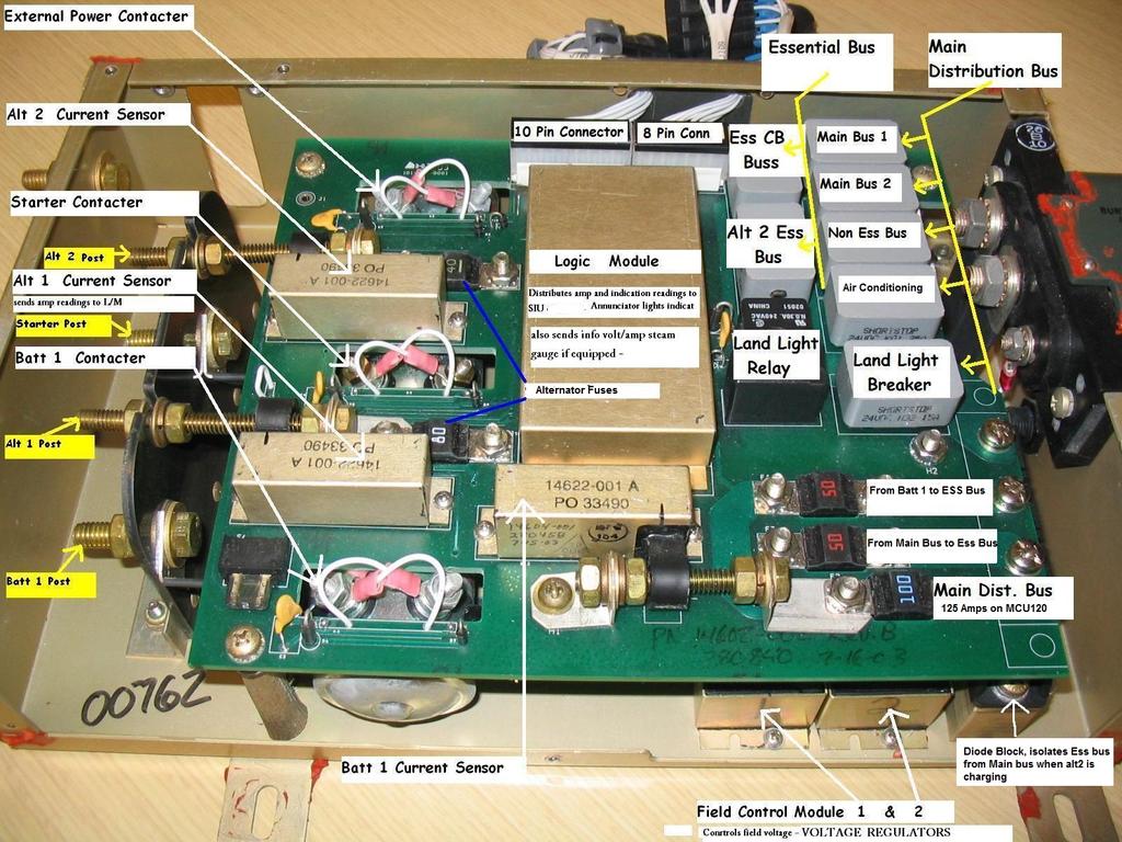
1 ALT #2 fail light on but Alternator is still charging (MCU 100/120): We have seen this happen a lot. The good news is there is probabl nothing wrong with the aircraft. Basic MCU Function: The MCU has a lot of components, but the main ones are: Field Control Modules: regulate the voltage output of the alternators. Current sensors: senses the current through the loop and sends the information to the logic module Logic Module: Reads the current levels from the sensors, reads the voltage level of the essential bus, and decides when the alternator fail light should turn on, and when the low volts light should turn on. ALT Fail Light Annunciation Logic: The logic module has trigger level for the alternator warning light we will call the light-on threshold. The light-on threshold is set at approximatel 3 amps *, so when the alternator current output drops below that threshold, the fail light will illuminate after a second dela to indicate that the output is low. If at an point the alternator output raises above the light-on threshold, the light will turn off and the dela timer will restart. The Logic Module will also provide a flashing ALT fail light which indicates an over charging condition. *Now in realit, the approximatel 3 amps light-on threshold is actuall anwhere from 3 amps all the wa up to 5 or 6 amps. Alternator and batter charging: Depending on how long the batter is left on before the alternators start charging, the alternator will charge at some higher level and slowl decrease its output as the batter charges back up. At some point the batter will become full charged, and the alternator output will stabilize to the level that is required to power the items that are on its electrical buss. Conditions that happen when the light-on threshold drifts too high: In a tpical SR20/SR22 with a MCU 100/110/120/130, when the batteries stabilize and the sstem is full charged, the alt#2 will charge approximatel 3-6 amps to power the items on the Essential and Avionics Essential busses. If the light-on threshold is below the alternators stabilized output, then the fail light will not turn on unless the alternators output drops below the threshold due to a failure So the light is operating normall. If the light-on threshold is at or around the same level as the alternators stabilized output, the ALT#2 Fail light will intermittentl turn on. (Some ma even go awa when ou transmit on the com, or turn on the pitot heat, etc. due to the initial spike in current, onl to come back shortl after when the dela timer has been reached). If the light-on threshold is above the stabilized output of the ALT#2, the fail light will remain on constantl, even though the alternator is charging just fine.
2 Possible Causes to the problem: There are man factors that can contribute an alternator fail light problem such as: Tolerances: current sensor output, logic module thresholds Corrosion: pins, connectors inside the MCU Drift: as parts age the drift awa from the original operating points Batter aging: As the batter ages it takes less charge An actual problem with the alternator charging sstem How to verif if alternator #2 is working: To verif that ALT#2 is working, all ou have to do is turn off alternator #1 and verif that the essential bus is still charging over 28V while the engine is running at 2000 RPM or higher. *For a more in depth MCU function check, see the attached check list. Possible fixes: First off, our Engineering department has recentl been made aware of this issue and the are working on a solution. In the mean time, it is not recommended to change out parts because the likelihood that the problem will not be corrected, or will return in a short time is ver high. If changing parts, be aware that all of the current sensors have some common reference voltages and grounds between them so one bad apple can spoil the bunch. If ou see a current indication that is pegged to the positive or negative extremes, then one or more of the current sensors is fault. Also be aware that corrosion can cause false fail light indications, false current indications, and actual charging problems.
3 CIRRUS AIRPLANE MAINTENANCE MANUAL MODELS SR22 AND SR22T 1 and caution lights illuminate. 2 Flap position light illuminates. 3 Engine instruments are operational and manifold pressure gage indicates approximatel the altimeter setting. 4 Ammeter select switch shows slight discharge in BAT position. (d) Start Engine and set engine speed at 1000 RPM. (e) Verif landing light, pitot heat, avionics, strobe lights, and navigation lights are on. (f) Switch ON and ON. (g) Increase RPM to (h) Check that LOW VOLT light is off and ammeter shows no current discharge in BAT position. (i) Increase RPM to (j) Check that LOW VOLT light is off and ammeter shows no current discharge in BAT position. (k) Switch ON and OFF. Verif and record operating values. Clock/Volts Voltmeter BAT LOW 27V V 27V - 28V Pos < 40A 0 - Pos 0A OFF OFF ON (l) Switch OFF and ON. Verif and record operating values. Clock/Volts Voltmeter BAT LOW 20V - 24V 28V - 29V 0A 0A - Neg 2A - 20A OFF ON OFF (m) Switch ON and ON. Verif and record operating values. Clock/Volts Voltmeter BAT LOW 27V V 28V - 29V Pos < 40A 0A - Pos 2A - 20A OFF OFF OFF Page Jun 2010 EFFECTIVITY: All
4 CIRRUS AIRPLANE MAINTENANCE MANUAL MODELS SR22 AND SR22T (n) Switch OFF and OFF. Verif and record operating values. Clock/Volts Voltmeter BAT LOW 20V - 24V 20V - 24V 0A Neg < 40A 0A ON ON ON (o) Shut down engine. (4) Operational Inspection - Master Control Unit - Serials w/ Perspective Avionics In order to perform the following check the engine must be operating. Do not stand or let anone else stand close to the arc of the airplane s propeller while conducting this check. (a) Verif all circuit breakers are set. (b) Toggle batter 2 master switch to the ON position and verif the following occurs: 1 Flap position light off. 2 Attitude gro low voltage flag hidden. 3 PFD powers up. 4 MFD is off. 5 Essential Bus voltage (indicated on PFD) is 22 to 26 volts. 6 and caution annunciations on PFD. (c) Toggle batter 1 master switch to the ON position and verif the following occurs: 1 Flap position light illuminates. 2 MFD powers up. 3 Pull PFD #1 circuit breaker and verif PFD remains on. 4 Reset PFD #1 circuit breaker. 5 Pull STDBY ATTD #1 circuit breaker and verif attitude gro voltage flag remains hidden. 6 Reset STDBY ATTD #1 circuit breaker. 7 Pull MFD #2 circuit breaker and verif MFD remains on. 8 Reset MFD #2 circuit breaker. 9 Switch on Landing Light and verif Landing Light illuminates. 10 Switch off Landing Light. 11 Serials w/ Fan or Air Conditioning: Turn on Cabin Fan and verif fan is on. 12 Serials w/ Fan or Air Conditioning: Turn off Cabin Fan. 13 and caution annunciations on PFD. 14 BAT 1 current indicator shows slight discharge. (d) Start Engine and set engine speed at 1000 RPM. (e) Switch ON and ON. (f) Verif landing light, pitot heat, avionics, strobe lights, and navigation lights are on. (g) Increase RPM to (h) Check that BAT 1,,, ESS BUS, M BUS 1, and M BUS 2 caution and warning annuncuations are off. (i) Increase RPM to (j) Check that BAT 1,,, ESS BUS, M BUS 1, and M BUS 2 caution and warning annuncuations are off. EFFECTIVITY: All Page Jan 2012
5
6 CIRRUS AIRPLANE MAINTENANCE MANUAL MODELS SR22 AND SR22T RELAY EXTERNAL POWER VOLT REG 100A 15A F B LANDING LIGHT 1 MAIN DIST LANDING LIGHT BAT 1 BAT 1 STARTER F B FUEL OIL LOW PITOT HEAT 50A 50A ESSENTIAL DIST VOLT REG 40A MASTER CONTROL UNIT 30A BAT 2 BAT 2 CIRCUIT BREAKER PANEL NON-ESSENTIAL MAIN BUS 1 TRAFF/TAWS GPS 2 COM 2 XPNDER XM/WX MFD AUDIO PANEL FUEL QUANTITY REC/INST LTS PITCH TRIM ROLL TRIM ICE PROTECT MAIN BUS 2 NON-ESSENTIAL FUEL PUMP TRN CRD #2 ATTITUDE #2 PFD #2 CABIN LTS 2A START RELAY PITOT/FAN 12V/ANR STROBE LTS NAV LTS FLAPS ESSENTIAL ESSENTIAL ANN/ENG IND TRN CRD #1 ATTITUDE #1 2A PFD #1 STALL WARN BATTERY 2 ESS POWER AUTOPILOT COM 1 GPS 1 2A ESSENTIAL RELAY ATT GYRO A/C 2 FAN COMPR/CTRL A/C 1 CONDENSER NON-ESSENTIAL RELAY NOTE Serials thru , thru and thru : 80A fuse. Serials thru , thru and thru : 100A fuse. Serials , , , & subs. SR22_MM24_1426F Page 2 15 Jun 2010 Figure Electrical Sstem Schematic - Serials w/o Perspective Avionics (Sheet 1 of 3) EFFECTIVITY: Serials w/o Perspective Avionics
SYSTEM LOAD CHARTS AND BUS SCHEMATICS
 SYSTEM LOAD CHARTS AND BUS SCHEMATICS 1. GENERAL The airplane is equipped with a two alternator system, with each alternator operating continuously. Serials 22-0002 thru 22-1601, 22-1603 thru 22-1820,
24-00 ELECTRICAL POWER
 ELECTRICAL POWER 1. GENERAL This chapter contains information on DC Generation, External Power, and Electrical Load Distribution. The airplane is equipped with a two-alternator, two-battery, 28-volt direct
CIRRUS AIRPLANE MAINTENANCE MANUAL
 ELECTRICAL LOAD DISTRIBUTION. DESCRIPTION The power distribution system for this airplane consists of the main distribution bus and the essential distribution bus in the MCU along with the associated buses
This chapter contains information on DC Generation, External Power, and Electrical Load Distribution.
 CIRRUS AIRPLANE MAINTENANCE MANUAL Electrical Power CHAPTER 24-00: ELECTRICAL POWER GENERAL 24-00: ELECTRICAL POWER 1. General This chapter contains information on DC Generation, External Power, and Electrical
DC Generation. 1. General. A. DC Generation
 CIRRUS AIRPLANE MAINTENANCE MANUAL DC Generation CHAPTER -0: DC GENERATION GENERAL -0: DC GENERATION 1. General (See Figure -0-1) This section covers the systems to generate, regulate, control, and indicate
CIRRUS AIRPLANE MAINTENANCE MANUAL
 STALL WARNING SYSTEM 1. DESCRIPTION A. Stall Warning System - Serials 05 thru 2015, 2016 & subs w/o Perspective Avionics The airplane uses an electro-pneumatic stall warning system. As the angle of attack
CHAPTER 24 - ELECTRICAL POWER TABLE OF CONTENTS
 ELECTRICAL POWER 24-00 General 1 Electrical Power - Serials w/o Perspective Avionics 1 Electrical Power - Serials w/ Perspective Avionics 1 Troubleshooting 2 DC GENERATION 24-30 Description 1 DC Generation
Attitude And Direction
 CIRRUS AIRPLANE MAINTENANCE MANUAL Attitude And Direction CHAPTER 34-20: ATTITUDE AND DIRECTION GENERAL 34-20: ATTITUDE AND DIRECTION 1. General This section contains information pertaining to those portions
Central Warning Systems
 CIRRUS AIRPLANE MAINTENANCE MANUAL Central Warning Systems CHAPTER 31-50: CENTRAL WARNING SYSTEMS GENERAL 31-50: CENTRAL WARNING SYSTEMS 1. General This section describes the Indicating/Recording Systems
24 ELECTRICAL DC ELECTRICAL SYSTEM DESCRIPTION
 24 ELECTRICAL DC ELECTRICAL SYSTEM DESCRIPTION The Direct Current electrical system provides power to most equipment through an electrical bus system. The power may be supplied from one of three sources:
Cessna Citation XLS - Electrical
 GENERAL Electrical power for the Citation XLS comes primarily from DC sources originating with the starter/ generators, the Auxiliary Power Unit (APU) or the battery. A receptacle below the left engine
CIRRUS AIRPLANE MAINTENANCE MANUAL
 CENTRAL WARNING SYSTEMS 1. GENERAL This section describes the Central Warning Systems which consists of a Crew Alerting System (CAS) and related sensors and switches. A. Crew Alerting System Aircraft annunciations
CIRRUS AIRPLANE MAINTENANCE MANUAL
 ANALYZERS - ENGINE MONITORING. DESCRIPTION This section describes that portion of the engine indicating system which is used to analyze engine performance, temperature, and condition. Serials 00 thru 8
CIRRUS AIRPLANE MAINTENANCE MANUAL
 MODEL SR0 INSTRUMENT AND CONTROL PANEL. DESCRIPTION Serials 00 thru 336, 337 thru w/o PFD: The airplane uses standard flight instruments arranged in the basic-six pattern. The airspeed indicator, attitude
STALL WARNING SYSTEM 1. DESCRIPTION A.
 STALL WARNING SYSTEM 1. DESCRIPTION A. Stall Warning System - Serials w/o Perspective Avionics The airplane uses an electro-pneumatic stall warning system. As the angle of attack increases and the airplane
CESSNA SECTION 4. Unless otherwise noted, the following speeds are based on a maximum weight of 2550 pounds and may be used for any lesser weight.
 CESSNA SECTION 4 INTRODUCTION Section 4 provides procedures and amplified instructions for normal operations using standard equipment. Normal procedures associated with optional systems can be found in
INTEGRATED ENGINE INSTRUMENT SYSTEMS
 All INTEGRATED ENGINE INSTRUMENT SYSTEMS. DESCRIPTION This section describes that portion of the engine indicating system which is used to analyze engine performance, temperature, and condition. Serials
CIRRUS AIRPLANE MAINTENANCE MANUAL
 MODEL SR FLIGHT ENVIRONMENTAL SYSTEMS. DESCRIPTION This section covers that portion of the system which senses environmental conditions and uses the data to influence navigation of the airplane. This includes
A. Stall Warning System - Serials w/o Ice Protection
 Stall Warning System GENERAL 27-31: STALL WARNING SYSTEM 1. General A. Stall Warning System - Serials w/o Ice Protection The airplane uses an electro-pneumatic stall warning system. As the angle of attack
CESSNA 172S NAV III VFR CHECKOUT POH EXAMINATION (Based on N1129K, serial no. 172S revised 10/05/06)
") INTRODUCTION, POH CESSNA 172S NAV III VFR CHECKOUT POH EXAMINATION (Based on N1129K, serial no. 172S10315 - revised 10/05/06) 1. Rate of climb at sea level: 2. Service ceiling: 3. Takeoff performance,
INTRODUCTION, POH CESSNA 172S NAV III VFR CHECKOUT POH EXAMINATION (Based on N1129K, serial no. 172S10315 - revised 10/05/06) 1. Rate of climb at sea level: 2. Service ceiling: 3. Takeoff performance,
Pilot's Operating Handbook Supplement AS-03
 POH / AFM SECTION 9 Pilot's Operating Handbook Supplement ASPEN EFD1000 PFD This supplement is applicable and must be inserted into Section 9 of the POH when the Aspen Avionics Evolution Flight Display
AIRPLANE FLIGHT MANUAL AQUILA AT01 AIRPLANE FLIGHT MANUAL - SUPPLEMENT AVE28 GLASS COCKPIT. equipped with ASPEN EFD1000 PFD
 SECTION 9 AIRPLANE FLIGHT MANUAL - SUPPLEMENT AVE28 GLASS COCKPIT equipped with ASPEN EFD1000 PFD This AFM supplement is applicable and must be inserted into Section 9 of the Airplane Flight Manual when
CIRRUS AIRPLANE MAINTENANCE MANUAL
 MODEL SR0 EXTERIOR LIGHTING. DESCRIPTION This section covers that portion of the system which provides illumination outside of the aircraft. This includes the landing light, anti-collision strobe light,
CIRRUS AIRPLANE MAINTENANCE MANUAL
 All ATTITUDE AND DIRECTION 1. DESCRIPTION This section contains information pertaining to those portions of the system which use magnetic, gyroscopic, and inertia forces. Included is the magnetic compass,
SR22 Airplane Flight Manual (AFM) Temporary Change
 Temporary Change") Cirrus Design TPOH Airplane Flight Manual (AFM) Temporary Change Information in this Temporary Change adds to, supersedes, or deletes information in the basic Pilot s Operating Handbook. Affected Publications:
Cirrus Design TPOH Airplane Flight Manual (AFM) Temporary Change Information in this Temporary Change adds to, supersedes, or deletes information in the basic Pilot s Operating Handbook. Affected Publications:
33-40 EXTERIOR LIGHTING
 EXTERIOR LIGHTING. DESCRIPTION This section covers that portion of the system which provides illumination outside of the aircraft. This includes the landing light, anti-collision strobe light, and recognition
CIRRUS AIRPLANE MAINTENANCE MANUAL
 INDICATING 1. DESCRIPTION This section describes that portion of the oil system which is used to indicate the quantity, temperature, and pressure of the oil. Components included are the oil filler cap/dipstick,
NORMAL CHECKLIST ATTENTION!
 Avion Training CHECKLIST Normal Checklist CESSNA 172R / TC-STS Cessna 172 R TC-STS NORMAL CHECKLIST ATTENTION! DO NOT STOW THIS CHECKLIST IN DIRECT SUNLIGHT Avion Training - Doc.nr. 212 Revision 1 / 02022018
CIRRUS AIRPLANE MAINTENANCE MANUAL
 MODEL SR0 FLIGHT ENVIRONMENTAL SYSTEMS. DESCRIPTION This section covers that portion of the system which senses environmental conditions and uses the data to influence navigation of the airplane. This
COLUMBIA 350 EMERGENCY PROCEDURES
 COLUMBIA 350 EMERGENCY PROCEDURES TABLE OF CONTENTS EMERGENCY PROCEDURES LANDING AND TAKEOFF Engine Failure During Takeoff...1 Engine Failure Immediately After Takeoff...1 Engine Failure During Climb to
ATTITUDE AND DIRECTION
 All ATTITUDE AND DIRECTION 1. DESCRIPTION This section contains information pertaining to those portions of the system which use magnetic, gyroscopic, and inertia forces. Included is the magnetic compass,
Vso 61. Vs1 63. Vr 70. Vx 76. Vxse 78. Vy 89. Vyse. 89 (blue line) Vmc. 61 (radial redline) Vsse 76. Va 134) Vno 163
 Vmc. 61 (radial redline) Vsse 76. Va 134) Vno 163") PA34-200T Piper Seneca II Normal procedures V-speeds Knots Vso 6 Vs 63 Vr 70 Vx 76 Vxse 78 Vy 89 Vyse Vmc 89 (blue line) 6 (radial redline) Vsse 76 Va 2-36(@4507lbs 34) Vno 63 Vfe 38 (0*)/2(25*)/07(40*)
PA34-200T Piper Seneca II Normal procedures V-speeds Knots Vso 6 Vs 63 Vr 70 Vx 76 Vxse 78 Vy 89 Vyse Vmc 89 (blue line) 6 (radial redline) Vsse 76 Va 2-36(@4507lbs 34) Vno 63 Vfe 38 (0*)/2(25*)/07(40*)
LOG OF REVISIONS. Model G58 Baron (Serials TH-2125 and After) Pilot s Operating Handbook and FAA Approved Airplane Flight Manual
 Pilot s Operating Handbook and FAA Approved Airplane Flight Manual") LOG OF REVISIONS Model G58 Baron (Serials TH-2125 and After) Pilot s Operating Handbook and FAA Approved Airplane Flight Manual Revision A12 - May, 2015 Title Page LOEP LOR Section 1 All Reformatted to
LOG OF REVISIONS Model G58 Baron (Serials TH-2125 and After) Pilot s Operating Handbook and FAA Approved Airplane Flight Manual Revision A12 - May, 2015 Title Page LOEP LOR Section 1 All Reformatted to
22-11 SYSTEM 55 AUTOPILOT
 SYSTEM 55 AUTOPILOT 1. DESCRIPTION This section covers those systems and components which use inputs to the system to automatically control the flight path of the aircraft through adjustment to the pitch/roll
C I R R U S DISTRIBUTION DESCRIPTION
 MODELS SR AND SRT DISTRIBUTION. DESCRIPTION This section contains information on the distribution system. The fuel distribution system consists of electric and mechanical (engine-driven) fuel pumps, fuel
Cessna 172S Skyhawk. AFTER LANDING CHECK RPM CHECK 2. Flaps UP 3. Transponder STANDBY 4. Strobes OFF 5. Contact Ground as Required. 121.
 PRE-LANDING CHECK 1. ATIS/AWOS/ASOS OBTAIN 2. Seat Belts CHECK 3. Autopilot OFF 4. Master Switch ON 5. Ignition BOTH 6. Circuit Breakers ALL IN 7. Landing Light AS REQ. 8. Mixture (Push) RICH 9. Fuel Selector
If, nonetheless, an emergency does arise, the guidelines given here should be followed and applied in order to clear the problem.
 3.1 INTRODUCTION 3.1.1 GENERAL This Chapter contains checklists as well as the description of recommended procedures to be followed in the event of an emergency. Engine failure or other airplane-related
FINAL EXAM. 3. Name the items on the control shift in the unmodified aircraft (non ASC-36).
.") FINAL EXAM Name 1. Total usable fuel is 177 gallons 2. Proper fuel(s) specification for the T-28 is (are): XX (a) 100/130 alternate 100LL (b) 115/145 and 100/130 alternate (c) 115/145 and 100/130 emergency
FINAL EXAM Name 1. Total usable fuel is 177 gallons 2. Proper fuel(s) specification for the T-28 is (are): XX (a) 100/130 alternate 100LL (b) 115/145 and 100/130 alternate (c) 115/145 and 100/130 emergency
CHAPTER 77 ENGINE INDICATING
 FBA-C, FBA-C CHAPTER 77 ENGINE INDICATING 77-00 Page July 4, 0 FBA-C, FBA-C List of Effective Pages Chapter / Section Page No. Date Chapter / Section Page No. Date 77-00 Jul 4, 0 Jul 4, 0 77-05 Jul 4,
CHAPTER 24 ELECTRICAL POWER
 CHAPTER 4 ELECTRICAL POWER 4-00 Page List of Effective Pages Chapter / Section Page No. Date Chapter / Section Page No. Date 4-00 Jul 4, 0 Jul 4, 0 4-0 Jul 4, 0 Jul 4, 0 Jul 4, 0 4 Jul 4, 0 5 Jul 4, 0
CIRRUS AIRPLANE MAINTENANCE MANUAL
 All INDICATING. DESCRIPTION A. Fuel Quantity Serials 005 thru 885: A fuel quantity gage is installed in the center console directly forward of the fuel selector valve. The fuel quantity gage indicates
Indicating. 1. General. A. Fuel Quantity. B. Fuel Flow
 Indicating GENERAL 28-40: INDICATING. General A. Fuel Quantity A dual reading fuel quantity indicator is displayed in the Fuel Qty block of the ENGINE page along calibrated vertical bars. The fuel quantity
FLIGHT SIMULATOR SYSTEMS
 FLIGHT SIMULATOR SYSTEMS 1. GENERAL This section describes systems required for simulator operation. This equipment includes the Cirrus Landing Gear Simulator (CLGS). 2. DESCRIPTION The intent of the CLGS
CIRRUS AIRPLANE MAINTENANCE MANUAL
 PASSENGER COMPARTMENT 1. DESCRIPTION This section covers the passenger compartment lighting. A. Passenger Eyeball Lights Individual eyeball-type reading lights are installed in the headliner above each
Diamond DA40 TDI OH-STL
 Diamond DA40 TDI OH-STL NORMAL, EMERGENCY AND ABNORMAL CHECKLISTS PREFLIGHT INTERIOR + EXTERIOR. 1 Check Aircraft papers 2 Remove pitot cover 3 Check interior for foreign objects 4 Check flight controls
EMERGENCY PROCEDURES TABLE OF CONTENTS
 CESSNA SECTION 3 TABLE OF CONTENTS Page Introduction............................................3-5 Airspeeds For Emergency Operations........................3-5.........................3-6 ENGINE FAILURES.....................................3-6
CHAPTER 96 ELECTRICAL SYSTEM
 CHAPTER 96 ELECTRICAL SYSTEM Section Title Page 96-00 Description.............................................. 96.1 96-10 Battery................................................. 96.3 96-11 Lead-Acid
CHAPTER 22 AUTOPILOT
 Section Title CHAPTER 22 AUTOPILOT 22-00 Description............................................... 22.1 22-10 (Pitch) Servo Assembly...................................... 22.3 22-20 (Roll) Servo Assembly.......................................
N123AX Piper Saratoga II HP (PA-32R-301) Checklist (v23 - Revision 3 April 2011) AIRSPEEDS FOR SAFE OPERATIONS. Best Rate of Climb (gear up, flaps up)
 Checklist (v23 - Revision 3 April 2011) AIRSPEEDS FOR SAFE OPERATIONS. Best Rate of Climb (gear up, flaps up)") N123AX Piper Saratoga II HP (PA-32R-301) Checklist (v23 - Revision 3 April 2011) AIRSPEEDS FOR SAFE OPERATIS Best Rate of Climb (gear down, flaps up) Best Rate of Climb (gear up, flaps up) Turbulent Air
N123AX Piper Saratoga II HP (PA-32R-301) Checklist (v23 - Revision 3 April 2011) AIRSPEEDS FOR SAFE OPERATIS Best Rate of Climb (gear down, flaps up) Best Rate of Climb (gear up, flaps up) Turbulent Air
Cessna 182S-CHECKLIST PROCEDURES
 Cessna 182S-CHECKLIST PROCEDURES PREFLIGHT INSPECTION 1 CABIN 1. Pitot Tube Cover -- REMOVE (if installed) and check for stoppage 2. Pilot s Operating Handbook AVAILABLE IN THE AIRPLANE 3. Airplane Weight
Cirrus SR20 Microsoft Flightsimulator 2002
 Cirrus SR20 Microsoft Flightsimulator 2002 Aircraft and Panel : Günter Kraemer Werner Schott Günter Kraemer Switzerland Germany w.schott@abbts.ch guenter@kraemerg.de Page 12 Page 1 Other simulator checklists
Expanded Flight Checklist Cessna 152
 OUTSIDE CHECK INSIDE CABIN 1 Magnetos... OFF 2 Mixture... IDLE CUT OFF 3 Master switch... ON 4 Fuel quantity... CHECKED 5 Master switch... OFF OUTSIDE CABIN 1 Left wing... CHECKED Surface condition Flap
CHECKLIST FOR NORMAL OPERATION PIPER P32R
 FLUGSCHULE GRENCHEN CHECKLIST Piper Saratoga SP 1 CHECKLIST FOR NORMAL OPERATION PIPER P32R Parameters, restrictions, procedures and emergency procedures see AFM BEFORE FIRST FLIGHT 1. Aircraft & Cockpit
Vr V STANDARD EQUIPMENT LIST
 Vr V5.02.09 STANDARD EQUIPMENT LIST IMPORTANT NOTE: this document is a general description of the aircraft equipment only. It is not a technical document and is to be used only for the purpose of generally
AIRSPEEDS FOR EMERGENCY OPERATIONS
 INTRODUCTION Section 3 provides checklist and amplified procedures for coping with emergencies that may occur. Emergencies caused by airplane or engine malfunctions are extremely rare if proper preflight
P68 Observer 2 STANDARD EQUIPMENT LIST V
 P68 Observer 2 STANDARD EQUIPMENT LIST V9.03.12 P68 OBSERVER 2 IMPORTANT NOTE: this document is a general description of the aircraft equipment only. It is not a technical document and is to be used only
EMERGENCY PROCEDURES ENGINE FIRE DURING START/GROUND OPERATIONS STARTER ENERGIZED ANNUNCIATOR ILLUMINATED. Memory items are printed in red.
 ENG FIRE-GRND, STARTER ENERGIZED EMERGENCY PROCEDURES Memory items are printed in red. ENGINE FIRE DURING START/GROUND OPERATIONS 1. Mixture...IDLE CUTOFF 2. Fuel Selector Valve... OFF 3. Battery, Alternator,
NORMAL PROCEDURRES CHECKLIST PA T SENECA II PREFLIGHT CHECK INSIDE CABIN OUTSIDE CABIN
 NORMAL PROCEDURRES CHECKLIST PA-34-200T SENECA II PREFLIGHT CHECK INSIDE CABIN Avionics Master Switch -- OFF Landing Gear Control. -- DOWN Mixture Controls -- IDLE/CUTOFF Ignition Switches -- OFF Master
CARENADO COPYRIGHTS. Normal & Emergency Checklist
 NORMAL PROCEDURES CHECKLIST PREFLIGHT CHECK Control wheel -- RELEASE BELTS Avionics -- OFF Master Switch -- ON Fuel quantity gauges -- CHECK Master switch -- OFF Ignition -- OFF Exterior -- CHECK FOR DAMAGE
INDEX: Normal Procedures Emergency Procedures Pre Flight Inspection NORMAL PROCEDURES BEFORE STARTING ENGINE
 INDEX: Normal Procedures Emergency Procedures Pre Flight Inspection NORMAL PROCEDURES BEFORE STARTING ENGINE 1. Preflight Inspection -- COMPLETE 2. Seats, Belts, Shoulder Harnesses -- ADJUST and LOCK 3.
SECTION 3 EMERGENCY PROCEDURES
 SECTION 3 TABLE OF CONTENTS Page Introduction... 3-3 Airspeeds for Emergency Operation... 3-5 CHECKLISTS Engine Failures... 3-6 Engine Failure During Takeoff Run... 3-6 Engine Failure Immediately After
Flight Environmental Systems
 CIRRUS AIRPLANE MAINTENANCE MANUAL Flight Environmental Systems CHAPTER 34-0: FLIGHT ENVIRONMENTAL SYSTEMS GENERAL 34-0: FLIGHT ENVIRONMENTAL SYSTEMS. General This section covers that portion of the system
4A.2 AIRSPEEDS FOR NORMAL OPERATING PROCEDURES
 Normal Operating DA 40 AFM 4A.1 INTRODUCTION Chapter 4A contains checklists and describes extended procedures for the normal operation of the airplane. 4A.2 AIRSPEEDS FOR NORMAL OPERATING PROCEDURES Flight
OPERATIONS MANUAL FTO SECTION : 06.04
 06.04.08. OO-WIK SECTION : 06.04 PARTENAVIA OO-WIK PAGE : 1 PRE ENTRY PITOT COVER - REMOVE SNOW / ICE CHECK AIRCRAFT NOSE INTO WIND AIRCRAFT WEIGHT & BALANCE WITHIN LIMITS EXTERNAL (COCKPIT FIRST) PARK
V - Speeds. RV-10 V fe Flaps Speeds Trail (0 deg) Half (15 deg) Full (30 deg) 122 kias 96 kias. 80 kias
 Half (15 deg) Full (30 deg) 122 kias 96 kias. 80 kias") RV-10 Check List V - Speeds RV-10 V fe Flaps Speeds Trail (0 deg) Half (15 deg) Full (30 deg) 122 kias 96 kias 87 kias V s1 Stall (Flap Up) 60 kias V s0 Stall (Flap 40 deg) 55 kias Best Glide 80 kias V
RV-10 Check List V - Speeds RV-10 V fe Flaps Speeds Trail (0 deg) Half (15 deg) Full (30 deg) 122 kias 96 kias 87 kias V s1 Stall (Flap Up) 60 kias V s0 Stall (Flap 40 deg) 55 kias Best Glide 80 kias V
Cessna 172RG WARNING. Maximum Demonstrated Crosswind. Takeoff or landing..15 KTS
 Cessna 172RG INTRODUCTION: This aircraft checklist contains information from the original manufacturer s Pilot Information Manual. Normal procedures associated with optional systems can be found in Section
Interior Pre Flight Documents: Check Control Wheel Lock: Remove Flight Controls: Check Instruments: Check for Damage Switches: Verify All Off Master
 Interior Pre Flight Documents: Check Control Wheel Lock: Remove Flight Controls: Check Instruments: Check for Damage Switches: Verify All Off Master Switch ALT/BAT: On Fuel Gauge: Check Quantity Flaps:
David s Flight Simulator Operations Manual
 DPW Solutions David s Flight Simulator Operations Manual Draft 0.2 David Woolterton Update 10/5/2016 Table of Contents Pre-Start Checklist... 2 Startup Checklist... 3 Before Taxi Checklist... 3 Taxi Checklist...
CHAPTER 6 ELECTRICAL SYSTEMS
 CHAPTER 6 ELECTRICAL SYSTEMS Page TABLE OF CONTENTS 06-00-01/02 DESCRIPTION General 06-10-01 Description 06-10-01 Controls and Indicators 06-10-02 COMPONENTS Circuit Breaker Panel Locations 06-20-01/02
TECNAM P2004 BRAVO N128LS
 TECNAM P2004 BRAVO N128LS GENERAL INFORMATION NORMAL PROCEDURES TIME SENSITIVE EMERGENCY TECNAM P2004 BRAVO CHECKLIST [FLIGHT PLAN DESIGNATION IS BRAV ] EMERGENCY CONTACT The following are First Landings'
Cessna 172P PPL Checklist Page 1
 Cessna 172P PPL Checklist 06-08-2017 Page 1 Cessna 172P PPL Checklist 06-08-2017 Page 2 Checklist Items Informational Items Critical Memory Items PREFLIGHT COCKPIT CHECK (DO-LIST) Pitot Cover -- REMOVE
Basic Ice Protection System
 Cirrus Design Section 9 Pilot s Operating Handbook and FAA Approved Airplane Flight Manual Supplement for Basic Ice Protection System When the Ice Protection System is installed on the aircraft, this POH
INDEX. Preflight Inspection Pages 2-4. Start Up.. Page 5. Take Off. Page 6. Approach to Landing. Pages 7-8. Emergency Procedures..
 INDEX Preflight Inspection Pages 2-4 Start Up.. Page 5 Take Off. Page 6 Approach to Landing. Pages 7-8 Emergency Procedures.. Page 9 Engine Failure Pages 10-13 Propeller Governor Failure Page 14 Fire.
TECNAM P92 EAGLET N615TA TECNAM P92 EAGLET CHECKLIST [FLIGHT PLAN DESIGNATION IS ECHO ]
![TECNAM P92 EAGLET N615TA TECNAM P92 EAGLET CHECKLIST [FLIGHT PLAN DESIGNATION IS ECHO ]](/thumbs/86/93080937.jpg "TECNAM P92 EAGLET N615TA TECNAM P92 EAGLET CHECKLIST [FLIGHT PLAN DESIGNATION IS ECHO ]") TECNAM P92 EAGLET CHECKLIST [FLIGHT PLAN DESIGNATION IS ECHO ] EMERGENCY CONTACT The following are First Landings' emergency contact telephone numbers. We ask that you call the numbers in the order listed.
TECNAM P92 EAGLET CHECKLIST [FLIGHT PLAN DESIGNATION IS ECHO ] EMERGENCY CONTACT The following are First Landings' emergency contact telephone numbers. We ask that you call the numbers in the order listed.
DASSAULT AVIATION Proprietary Data
 F2000EX EASY 02-49-00 CODDE 1 PAGE 1 / 2 TABLE OF CONTENTS 02-49 02-49-00 TABLE OF CONTENTS 02-49-05 GENERAL Introduction Sources Equipment location 02-49-10 DESCRIPTION Introduction Description Operating
Checklist für Diamond DA40 TDI G1000
 Checklist für Diamond DA40 TDI G1000 Edition #: 17 Edition date: 01.03.2015 Please observe: The file you are receiving hereby combines all three sections of the checklist: Normal Checklist, Emergency Checklist
CHECKLIST FOR NORMAL OPERATION ROBIN DR40
 FLUGSCHULE GRENCHEN CHECKLIST Robin Remo 200 1 CHECKLIST FOR NORMAL OPERATION ROBIN DR40 Parameters, restrictions, procedures and emergency procedures see AFM BEFORE FIRST FLIGHT 1. Aircraft & Cockpit
Model No. SB1B-14 Linear Standby Regulator. B & C Specialty Products P.O. Box B Newton, KS (316)
") Installation Instructions for Model No. SB1B-14 Linear Standby Regulator With Over-Voltage Protection B & C Specialty Products P.O. Box B Newton, KS 67114 (316) 283-8000 SB1B-14_Install, Rev. A (12/12/14)
Installation Instructions for Model No. SB1B-14 Linear Standby Regulator With Over-Voltage Protection B & C Specialty Products P.O. Box B Newton, KS 67114 (316) 283-8000 SB1B-14_Install, Rev. A (12/12/14)
Wiring diagrams on page 29 are for reference only. For detailed vehicle wiring refer to Navistar documents.
 1 10/2014 REV 7 !!Attention!! Before performing diagnostics: Wiring diagrams on page 29 are for reference only. For detailed vehicle wiring refer to Navistar documents. Check for Fault Codes using the
PA , Model E Normal Checklist (04/15/11)
") PA-23-250, Model E Normal Checklist (04/15/11) Key Airspeeds IAS-MPH V NE 249 V NO 198 V LO/LE 150 V A (At max gross weight.) 149 Speed for single engine cruise. 138 V FE Quarter Flaps 160 Half Flaps 140
PA-23-250, Model E Normal Checklist (04/15/11) Key Airspeeds IAS-MPH V NE 249 V NO 198 V LO/LE 150 V A (At max gross weight.) 149 Speed for single engine cruise. 138 V FE Quarter Flaps 160 Half Flaps 140
SERVICE NOTICE. 1. The configuration of each Garmin LRU specific to the KODIAK The Garmin LRU software.
 SUBJECT: G1000 Configurations and Updates EFFECTIVITY: As required BACKGROUND This Service Notice is to make customers aware of the different software configurations available for their G1000-equipped
Dash8 - Q400 - Pneumatics
 12.19.1 Introduction The Auxiliary Power Unit (APU) replaces the standard composite tailcone with a titanium tailcone and firewall. The APU is accessed by two clamshell type doors on the bottom of the
King Air B90. Speeds (KIAS)
") King Air B90 Speeds (KIAS) V MCA 92 V SSE (101) Derived from C90 V X 101 V Y 114 Down to 103 @ 30 000 V XSE 101 V YSE 110 Down to 101 @ 24 000 V A 169 V R 92 V 1 101 V MO 208 V FE 174 35% 130 100% V LE
King Air B90 Speeds (KIAS) V MCA 92 V SSE (101) Derived from C90 V X 101 V Y 114 Down to 103 @ 30 000 V XSE 101 V YSE 110 Down to 101 @ 24 000 V A 169 V R 92 V 1 101 V MO 208 V FE 174 35% 130 100% V LE
VC-4820 Programmable DC-DC Converter with Battery Charger function USER'S MANUAL
 1. INTRODUCTION VC-4820 Programmable DC-DC Converter with Battery Charger function USER'S MANUAL This MCU controlled Step Down DC-DC Converter has a digitally adjustable output in 0.2V increments. This
CIRRUS SR2X SB 2X Service Bulletin. Issued: February 27, SNS SUBJECT: TEMPERATURE CONTROL - Cabin Air Coupler Actuator Rigging
 CIRRUS SR2X Service Bulletin Number: Issued: February 27, 2012 SNS SUBJECT: 21-60 TEMPERATURE CONTROL - Cabin Air Coupler Actuator Rigging 1. COMPLIANCE Recommended, On Condition: Accomplish this Service
Checklist LN-DAG SFK 2014
 Checklist LN-DAG SFK 2014 2 GROUND Exsterior Checklist 1. Fuel (wings & filter) - Drained 2. Documents - Checked 3. Fire extinguisher, first aid sur. kit - Checked 4. Magnetos - Off 5. Master switch -
NOTE: SB is a WAAS only supported build. If the autopilot is not WAAS equipped, the unlock card cannot be used at this time.
 Single Engine Service Bulletin July 22, 2011 TITLE GARMIN G1000 / FLINT AERO, INC AUXILIARY FUEL GALLON REMAINING ENABLEMENT EFFECTIVITY The following airplanes equipped with the Garmin G1000 Nav III Avionics
Pilot Training C150 CHECKLIST
 Gunnedah Aero Club Pilot Training C150 CHECKLIST How to use the checklist. Conduct the checks up to (but not including the start) by memory. Then, use the checklist to confirm the checks were completed.
Pilatus PC-12. Checklist
 Checklist Before Engine Start 1 Pre- Flight Inspection Completed 2 Parking Brake Set 3 Flight Control Lock Removed 4 Oxygen Lever On 5 Pax Oxy Supply Auto 6 Oxygen Mask Checked 7 Circuit Breakers Checked
ATP Aircraft Registration Profile
 ADs Aircraft Registration Profile 10/21/2014 Profile ID: Created: 10/7/2014 Changed: 10/21/2014 Owner/Operator: KILO ECHO LLC Contact: Address: 341 Raven Circle, Wyoming, Delaware 19934-4033 USA Phone:
SECTION 2-05 ELECTRICAL
 SECTION 2-05 TABLE OF CONTENTS Block General...2-05-05...01 DC System...2-05-05...02 DC System Protection...2-05-05...04 External Power Source...2-05-05...05 Batteries...2-05-05...06 Backup Battery...2-05-05...07
CESSNA 182 CHECKLIST. LEFT WING Trailing Edge 1. Aileron CHECK freedom of movement and security
 CESSNA 182 CHECKLIST PRE-FLIGHT INSPECTION CABIN 1. Pilot s Operating Handbook AVAILABLE IN THE AIRPLANE (A.R.R.O.W.E) 2. Landing Gear Lever DOWN 3. Control Wheel Lock REMOVE 4. Ignition Switch OFF 5.
Advanced Troubleshooting Guide Snorkel V Battery Charger Rev 0 3JAN07
 Advanced Troubleshooting Guide Snorkel 3050097 24V Battery Charger Rev 0 3JAN07 1. How It Works: The 3050097 charger converts AC voltage to DC voltage, then uses high frequency to re-convert it to DC voltage/current
CIRRUS AIRPLANE MAINTENANCE MANUAL
 SYSTEM 55 AUTOPILOT 1. DESCRIPTION The S-TEC System 55 is a dual axis autopilot system that provides roll stability, heading hold, NAV/GPS tracking, altitude hold, vertical speed selection, automatic glideslope
FBA-2C3, FBA-2C4 CHAPTER 33 LIGHTS. Uncontrolled Copy
 FBA-C, FBA-C CHAPTER LIGHTS -00 Page July 4, 0 FBA-C, FBA-C List of Effective Pages Chapter / Section Page No. Date Chapter / Section Page No. Date -00 Jul 4, 0 Jul 4, 0 - Jul 4, 0 Jul 4, 0 Jul 4, 0 4
Preflight Inspection Cabin EMPENNAGE RIGHT WING Trailing Edge RIGHT WING NOSE
 Preflight Inspection Cabin 1. Control Wheel Lock REMOVED 2. Ignition Switch OFF 3. Avionics Power Switch OFF 4. Master Switch ON 5. Fuel Quantity Indicators CHECK QUANTITY 6. Master Switch OFF 7. Fuel
JP AVIONICS VOLTAGE WARNING LIGHT INSTALLATION MANUAL. Date: Rev: 2
 INSTALLATION MANUAL CONTENTS CONTENTS 2 PREFACE 3 INTRODUCTION 4 WORKING PRINCIPLE 5 SPECIFICATIONS 7 INSTALLATION 8 WIRING DIAGRAM 10 USER GUIDE 11 JP Avionics, 2009, 2010. All rights reserving, no part
C I R R U S CONTROLLING DESCRIPTION
 CONTROLLING 1. DESCRIPTION Serials 22-0002 & subs: An electric two-speed fuel pump provides boost (low speed) and prime (high speed) for the engine. A console mounted rocker switch located on the center
Jump to Table of Contents
 Jump to Table of Contents PIPER AIRCRAFT CORPORATION PA-28R-201, CHEROKEE ARROW III SECTION 3 EMERGENCY PROCEDURES 3.3 EMERGENCY PROCEDURES CHECK LIST ENGINE FIRE DURING
Van s Aircraft RV-7A. Pilot s Operating Handbook N585RV
 Van s Aircraft RV-7A Pilot s Operating Handbook N585RV PERFORMANCE SPECIFICATIONS SPAN:..25 0 LENGTH...20 4 HEIGHT:.. 7 10 SPEED: Maximum at Sea Level...180 knots Cruise, 75% Power at 8,000 Ft...170 knots