SECTION 3 EMERGENCY PROCEDURES
|
|
|
- Sherilyn Brooks
- 5 years ago
- Views:
Transcription
1 SECTION 3 TABLE OF CONTENTS Page Introduction Airspeeds for Emergency Operation CHECKLISTS Engine Failures Engine Failure During Takeoff Run Engine Failure Immediately After Takeoff Engine Failure During Flight Rough Running Engine or Partial Loss of Power Maximum Glide Chart Forced Landings Emergency Landing Without Engine Power Precautionary Landing With Engine Power Ditching Fires During Start On Ground Engine Fire in Flight Electrical Fire in Flight Cabin Fire Wing Fire Icing Inadvertent Icing Encounter Static Source Blocked Abnormal Landings Landing With a Flat Main Tire Landing With a Flat Nose Tire Electrical Power Supply System Malfunctions Over Voltage Light Illuminates During Flight Under Voltage Light Illuminates During Flight Electrical System Failure Engine Monitor Failure
2 SECTION 3 FOUND TABLE OF CONTENTS Page Vacuum Failure Electric Trim Failure G500 Primary/Multi-function Flight Display Failure AMPLIFIED Engine Failure Forced Landings Landing Without Elevator Control Fires Static Source Blocked Spins Rough Engine Operation or Loss of Power Improper Mixture / Fuel Starvation Spark Plug Fouling Low Oil Pressure Electrical Power Supply System Malfunctions Excessive Rate of Charge Insufficient Rate of Charge Alternator Failure at night or IFR Flight Other Emergencies Windshield Damage Garmin G500 Abnormal procedures G500 Abnormal Indication
3 INTRODUCTION Section 3 provides the operational checklists and amplified procedures to deal with abnormal circumstances and emergencies which may occur on the ground or during flight. Emergencies due to airplane or engine malfunctions are very rare especially if proper preflight inspections, operating procedures, and airplane maintenance and care are adhered to. Other emergencies caused by enroute weather conditions can be avoided by careful planning of the flight, and by using good judgement should unfavourable weather conditions be encountered. In any event, in order to be prepared for any such emergency, pilots should familiarize themselves with the basic guidelines of this section. Emergency procedures associated with the Emergency Locator Transmitter (ELT) and other optional systems will be found in Section 7 and 9 respectively. 3-3
4 SECTION 3 FOUND INTENTIONALLY LEFT BLANK 3-4
5 AIRSPEEDS FOR EMERGENCY OPERATION CONDITION KIAS Engine Failure after Takeoff (Flaps 20 o ) 72 Maneuvering Speed 118 Precautionary Landing with Engine Power 70 Best Glide Speed 90 Landing Without Engine Power: Wing Flaps Up Wing Flaps Down DOT APPROVED 3-5
6 SECTION 3 FOUND CHECKLISTS ENGINE FAILURES ENGINE FAILURE DURING TAKEOFF RUN 1. Throttle... IDLE 2. Brake... APPLY AS REQUIRED If time permits: 3. Flaps... RETRACT 4. Mixture... IDLE CUT-OFF 5. Ignition Switch... OFF 6. Master Switch... OFF 7. Alternator Switch... OFF ENGINE FAILURE IMMEDIATELY AFTER TAKEOFF 1. Land... LAND straight ahead Straight ahead turning only to avoid obstacles. 2. Airspeed KIAS (Flaps 20 ) If time permits: 3. Mixture... IDLE CUT-OFF 4. Fuel Shutoff Valve... OFF 5. Ignition Switch... OFF 6. Master Switch... OFF 7. Alternator Switch... OFF 8. Flaps... AS REQUIRED ENGINE FAILURE DURING FLIGHT (Restart Procedures) 1. Airspeed KIAS (Flaps 0 ) 2. Throttle... FULL BACK 3. Propeller... COARSE (full back) 4. Fuel Selector Valve... TO TANK WITH MOST FUEL 5. Auxiliary Fuel Pump Switch... ON 6. Mixture... RICH 7. Alternate Induction Air... OPEN 8. Ignition Switch... BOTH (or START if propeller stopped) 9. If engine does not start, proceed to Forced Landings checklist, as required. 3-6 DOT APPROVED
7 ROUGH RUNNING ENGINE OR PARTIAL LOSS OF POWER 1. Mixture... RICH 2. Auxiliary Fuel Pump Switch... ON 3. Ignition Switch... BOTH Check OAT and look for evidence of possible icing conditions. If problem persists after several minutes: 4. Mixture... Progressively LEAN (Do not exceed Max EGT) 5. Alternate Induction Air... OPEN If smooth operation is not possible, ensure the mixture is in the RICH setting and proceed to the nearest suitable airport. Monitor engine temperatures and pressures and be prepared for an engine failure or possible need to shut down the engine. DOT APPROVED 3-7

8 SECTION 3 FOUND MAXIMUM GLIDE Figure 3-1 Maximum Glide 3-8 DOT APPROVED
9 FORCED LANDINGS EMERGENCY LANDING WITHOUT ENGINE POWER 1. Seats... SECURE 2. Seat belts... FASTENED 3. Loose Articles... SECURE 4. Airspeed KIAS (Flaps UP) 70 KIAS (Flaps 30 ) Before touchdown: 5. Mixture... IDLE CUT-OFF 6. Auxiliary Fuel Pump Switch... OFF 7. Fuel Shutoff Valve... OFF 8. Ignition Switch... OFF 9. Master Switch... OFF 10. Alternator Switch... OFF 11. Doors... UNLATCH PRIOR TO TOUCHDOWN After touchdown: 12. Brakes... APPLY AS REQUIRED PRECAUTIONARY LANDING WITH ENGINE POWER 1. Seats... SECURE 2. Seat Belts... FASTENED 3. Loose Articles... SECURE 4. Airspeed KIAS Minimum 5. Flaps... UP 6. Selected Field... FLY OVER Note terrain and obstructions. 7. Radio and Electrical Switches... OFF 8. Flaps o (or 30 for steep approach) 9. Airspeed KIAS 10. Propeller... HIGH RPM 11. Doors... UNLATCH PRIOR TO TOUCHDOWN DOT APPROVED 3-9
10 SECTION 3 FOUND After touchdown: 12. Ignition Switch... OFF 13. Master Switch... OFF 14. Alternator Switch... OFF 15. Brakes... APPLY AS REQUIRED. DITCHING 1. Radio... TRANSMIT MAYDAY (on MHz giving LOCATION and INTENTIONS and Squawk 7700) 2. Heavy Objects, Loose Articles... SECURE 3. Seats... SECURE 4. Seat Belts... FASTENED 5. Flaps o 6. Doors... UNLATCH PRIOR TO TOUCHDOWN 7. Power... 3 deg Approach Establish 350 FPM descent at 70 KIAS 8. Approach... as follows High Winds Heavy Seas - INTO WIND Light Winds Heavy Swells - PARALLEL TO SWELLS 9. Touchdown... LEVEL ATTITUDE at ESTABLISHED RATE OF DESCENT 10. Airplane... EVACUATE through the doors 11. Life Vests and Raft... INFLATE when clear of the airplane 3-10 DOT APPROVED
11 FIRES DURING START ON GROUND IF ENGINE STARTS 1. Power... IDLE 2. Engine... SHUTDOWN AND INSPECT IF ENGINE FAILS TO START 3. Mixture... IDLE CUTOFF 4. Throttle... BACK 5. Engine... SECURE a. Master Switch... OFF b. Alternator Switch... OFF c. Ignition Switch... OFF d. Fuel Shut-Off Valve... OFF e. Auxiliary Fuel Pump Switch... OFF 6. Fire Extinguisher... OBTAIN 7. Fire... EXTINGUISH 8. Fire Damage... INSPECT ENGINE FIRE IN FLIGHT 1. Mixture... IDLE CUTOFF 2. Throttle... BACK 3. Fuel Shutoff Valve... OFF 4. Auxiliary Fuel Pump Switch... OFF 5. Master Switch... OFF 6. Alternator Switch... OFF 7. Cabin Heat and Air... OFF 8. Airspeed KIAS If fire not extinguished, increase glide speed to find an incombustible mixture, within airspeed limitations 9. Forced Landing... EXECUTE (as described in Emergency Landing Procedures Without Engine Power) DOT APPROVED 3-11
12 SECTION 3 FOUND ELECTRICAL FIRE IN FLIGHT 1. Master Switch... OFF 2. Alternator Switch... OFF 3. Vents, Cabin Air, Heat... CLOSE 4. Fire Extinguisher... ACTIVATE 5. Avionics Master Switch... OFF 6. All Other Switches (except Ignition)... OFF 7. Vents/Cabin Air/Heat... OPEN, when fire is completely extinguished. WARNING AFTER DISCHARGING FIRE EXTINGUISHER AND VERIFYING THAT FIRE HAS BEEN EXTINGUISHED, VENTILATE THE CABIN AIR. IF IT CANNOT BE DETERMINED VISUALLY THAT THE FIRE HAS BEEN EXTINGUISHED, LAND IMMEDIATELY. If fire has been extinguished and electrical power is necessary for continuance of flight to nearest suitable airport or landing area: 8. Master Switch... ON 9. Alternator Switch... ON 10. Circuit Breakers... Check for Faulty Circuit DO NOT RESET 11. Radio Switches... OFF 12. Avionics Master Switch... ON 13. Radio/Electrical Switches... ON one at a time as required, with delay after each until short circuit is localized. If short circuit is localized turn switch off DOT APPROVED
13 CABIN FIRE 1. Master Switch... OFF 2. Vents, Cabin Air, Heat... CLOSE 3. Fire Extinguisher... ACTIVATE 4. Vents/Cabin Air/Heat... OPEN, when fire is completely extinguished. WARNING AFTER DISCHARGING FIRE EXTINGUISHER AND VERIFYING THAT FIRE HAS BEEN EXTINGUISHED, VENTILATE THE CABIN AIR. IF IT CANNOT BE DETERMINED VISUALLY THAT THE FIRE HAS BEEN EXTINGUISHED, LAND IMMEDIATELY. 5. Land the airplane as soon as possible to inspect for damage. WING FIRE 1. Navigation Light Switch... OFF 2. Strobe Light Switch... OFF 3. Pitot Heat Switch... OFF NOTE Perform a sideslip to keep the flames away from the wing fuel tank and cabin. Land as soon as possible using flaps only as required for final approach and touchdown. DOT APPROVED 3-13
14 SECTION 3 FOUND ICING INADVERTENT ICING ENCOUNTER Flying into known icing conditions is strictly prohibited and extremely dangerous. However an inadvertent encounter with icing conditions may possibly occur. The checklist procedures for this emergency should be adhered to and turning back and/or changing altitude to escape icing conditions is highly advisable. 1. Turn pitot heat switch ON. 2. Turn back or change altitude to obtain an outside air temperature that is less conducive to icing. 3. Cabin heat to maximum and defrost full open to obtain maximum windshield defroster airflow. 4. Open Alternate Induction Air. 5. Watch for signs of engine related icing conditions. An unexplained loss in engine speed could be caused by ice blocking the air intake filter. Change the throttle position to obtain maximum RPM. This may require either advancing or retarding the throttle, dependent on where ice has accumulated in the system. Adjust the mixture as required for maximum RPM. 6. Plan a landing at the nearest airport. With an extremely rapid build-up of ice, select a suitable off-airport site. 7. With ice accumulation of 1/4-inch or more on the wing leading edges, be prepared for a significantly higher stall speed. 8. Leave flaps retracted. With a severe build-up of ice on the horizontal tail, the change in wing wake airflow direction caused by the extension of the flaps could result in loss of elevator effectiveness 9. Approach at 80 to 90 KIAS depending upon the amount of ice accumulation. 10. Perform a landing in level attitude DOT APPROVED
15 STATIC SOURCE BLOCKED (SUSPECTED ERRONEOUS INSTRUMENT READINGS) 1. Alternate Static Source Switch... ON 2. Pitot Heat... ON 3. Airspeed... Consult appropriate calibration table in Section 5. NOTE In an emergency, on airplanes not equipped with an alternate static source, the cabin pressure can be supplied to the static pressure instruments by breaking the glass in the face of the vertical speed indicator. The vertical speed indication will be reversed in this case (i.e. the needle will indicate DOWN for climb and UP for descent). DOT APPROVED 3-15
16 SECTION 3 FOUND ABNORMAL LANDINGS LANDING WITH A FLAT MAIN TIRE 1. Approach... NORMAL 2. Flaps o 3. Airspeed KIAS 4. Touchdown... GOOD MAIN TIRE FIRST (hold the airplane off flat tire as long as possible using ailerons) 5. Directional Control... MAINTAIN using brake on good wheel as required. LANDING WITH A FLAT NOSE TIRE 1. Approach... NORMAL 2. Flaps o 3. Airspeed KIAS 4. Touchdown... ON MAIN TIRES FIRST (hold the nose wheel off the ground as long as possible) 5. Elevator Control... MAINTAIN full up as airplane slows to a stop DOT APPROVED
17 ELECTRICAL POWER SUPPLY SYSTEM MALFUNCTIONS OVER VOLTAGE LIGHT ILLUMINATES DURING FLIGHT (Ammeter Indicates Excessive Rate of Charge) 1. Alternator Switch... OFF 2. Non-essential Electrical Equipment... OFF 3. Flight... Land as soon as practical. UNDER VOLTAGE LIGHT ILLUMINATES DURING FLIGHT (Ammeter Indicates Discharge) NOTE Illumination of the UNDER VOLTAGE LIGHT may occur during low RPM conditions with an electrical load on the system such as during a low RPM taxi. Under these conditions, the light will go out at higher RPM. 1. Avionics Power Switch... OFF 2. Master Switch... OFF 3. Alternator Switch... OFF 4. Alternator Circuit Breaker... CHECK IN 5. Master Switch... ON 6. Alternator Switch... ON 7. Under Voltage Light... CHECK OFF 8. Avionics Master Switch... ON If UNDER VOLTAGE LIGHT illuminates again: 9. Alternator Switch... OFF 10. Non-essential Electrical Equipment... OFF 11. Flight... Land as soon as practical. DOT APPROVED 3-17
18 SECTION 3 FOUND ELECTRICAL SYSTEM FAILURE In the event of the total failure of the electrical system it may be possible to recover some electrical power by activating the Backup Power Switch. This switch bypasses the main bus and feeds electrical power directly to the engine monitor and overhead crew light. Along with the engine monitor and overhead crew light the following instruments are still operable without primary electrical power: Airspeed Indicator (Pitot-Static System) Altimeter (Pitot-Static System) Vertical Speed Indicator (Pitot-Static System) Attitude Indicator (Vacuum System) Heading Indicator (Vacuum System) 1. Backup Power Switch... ON 2. Crew Light Switch... ON as required 3. Alternator Switch... OFF 4. Land as soon as practical NOTE Flap angle cannot be changed under this condition. ENGINE MONITOR FAILURE In the event of the loss of the engine monitor display the position of the engine controls shall be used to establish engine condition. 1. Mixture... PUSH FULL RICH 2. Pitch... PUSH FULL FINE 3. Throttle... AS REQUIRED 4. Land as soon as practical 3-18 DOT APPROVED
19 VACUUM FAILURE (Indicated by a reading below 4.5 psi. The digital readout on the monitor will change colour from green to white when this occurs) 1. Vacuum Indicator... CHECK to ensure vacuum within normal operating limits. WARNING FAILURE OF THE VACUUM SYSTEM WILL RESULT IN ERRONEOUS AND UNRELIABLE INDICATIONS ON THE STANDBY ATTITUDE INDICATOR. DOT APPROVED 3-19
20 SECTION 3 FOUND ELECTRIC TRIM FAILURE Any failure or malfunction of the electric rudder trim can be easily overcome by use of the opposing rudder input. If runaway trim is the problem, de-energize the circuit by pulling the circuit breaker and land as soon as conditions permit. 1. Airplane Control... MAINTAIN MANUALLY 2. Circuit Breaker... OFF (Pull Out) 3. Control Yoke/Rudder Pedal... HOLD PRESSURE 4. Land as soon as practical. 5. Conduct a normal descent, approach and landing. G500 PRIMARY/MULTI-FUNCTION FLIGHT DISPLAY FAILURE If the malfunction results in improper information from the air data computer and/or an abnormal display of attitude information, use the standby instruments. The loss of air data (altitude, airspeed) is indicated by the affected indicator being removed from the display and replaced with a red X. Loss of attitude data (pitch, roll, heading) is indicated by the affected indicator being removed from the display and replaced with a red X. If the MFD should malfunction or perform improperly, you may continue to utilize those portions of the MFD data that are not in question. Moving map errors may be associated with a LOI (Loss of Integrity) alarm indicating the loss of adequate GPS position containment. Data or functions that have failed are typically removed and replaced with a red X in the appropriate area. Those functions that do not have a red X may still be usable. AUTOPILOT If the autopilot should malfunction or perform improperly, do not attempt to identify or analyze the problem. If the malfunction results in an abnormal change in the pitch and/or roll axis, immediately regain control of the airplane by the disengaging the autopilot using either the pilot s red disengagement button located on the control wheel. Do not, under any circumstances, reengage an autopilot that has malfunctioned until the problem is corrected DOT APPROVED
21 AMPLIFIED The following amplified emergency procedures provide further insight upon the information contained in the emergency procedures checklists of this section. These amplified emergency procedures also include information which cannot be adapted into a checklist format and which is not practical to refer to during a specific emergency. As such, this information should be reviewed in detail before flying the airplane and should also be reviewed on a regular basis to maintain pilot proficiency on the procedures. ENGINE FAILURE If an engine failure occurs during the takeoff roll, the most important thing to do is stop the airplane on the remaining runway, if possible. The additional items shown on the checklist will provide added safety after a failure of this type. Prompt lowering of the nose in order to maintain safe airspeed and to establish a glide attitude is the first response to an engine failure immediately after takeoff. In most cases, the landing should only be planned straight ahead as there is often not enough altitude and airspeed to attempt safely a 180 degree turn and return to the airfield. Only small changes in direction should be taken to avoid obstructions. The checklist procedures do assume, however, that there is adequate time to secure the fuel and ignition systems of the airplane prior to touchdown. The most important course of action following an engine failure in flight is to continue flying the airplane. The Best-Glide-Speed (90 KIAS) should be established as quickly as possible. Having selected a suitable landing area, the pilot should try to identify the cause of the failure and attempt an engine restart. If time permits, this engine restart should be conducted as shown in the checklist. If the engine cannot be restarted, a forced landing without power will inevitably occur. Follow the procedures for an Emergency Landing without Engine Power as shown in the emergency procedures checklists. 3-21
22 SECTION 3 FOUND FORCED LANDINGS The first step to executing a successful forced landing is to select a suitable field as early as possible. After choosing a suitable field, preparations for the landing can begin, as outlined in the emergency procedures checklist for Emergency Landing without Engine Power. Ensure that a Mayday message is transmitted on MHz giving your location and intentions and that you squawk 7700 on your transponder. In precautionary landings with engine power, the pilot should first fly over the landing area at a safe but low altitude and inspect the ground features for obstructions and surface conditions. The pilot can then proceed as shown in the Precautionary Landing with Engine Power Checklist. In the event of a ditching attempt over water, collect items such as a folded coat to protect the occupants face at touchdown. A Mayday transmission on MHz giving location and intentions should be effected and the transponder should be set to squawk A landing flare prior to touchdown should be avoided because of the difficulty in judging height over the water surface. When ditching with no engine power, the airspeeds associated with minimum flap extension allow for a more favourable attitude during a power off ditching. To prevent disabling the airplane s electrical systems prematurely during a forced landing, the avionics master and master switches should not be turned off until a landing is assured. For more detailed information on the ELT and its operation, refer to Section 9 Supplements in this Pilot s Operating Handbook. LANDING WITHOUT ELEVATOR CONTROL Loss of elevator control during flight requires use of the throttle and pitch (stabilizer) trim to maintain control. A touchdown with power on will likely be required, especially when at maximum forward C.G. position, and a landing site which provides a longer than normal landing run should be selected if available. With air speed of approximately 80 KIAS and flaps up, adjust the pitch trim and throttle to maintain horizontal flight. Airspeed and rate of descent can be controlled by small corrections in throttle position and pitch trim. 3-22
23 During a flare out, power reduction will cause a significant nose down pitching moment. Coordination of pitch trim with throttle position reduction is required to perform the flare and to reduce airspeed. If the pitch trim is at full nose up position, a slight increase in engine power will provide a nose up pitch if required. WARNING AT EXTREME FORWARD CG POSITIONS, INSUFFICIENT NOSE UP PITCH TRIM MAY BE AVAILABLE FOR A LANDING FLARE WITH PITCH TRIM ALONE. A SLIGHT INCREASE IN ENGINE POWER WILL PROVIDE THE REQUIRED NOSE UP PITCHING MOMENT. FIRES If an engine fire occurs during flight, the checklist procedure outlined for Engine Fire in Flight should be followed. Having extinguished the fire, execute the Forced Landings procedure and do not attempt to restart the engine. Electrical fires can often be detected from the obvious odour of burning insulation. Immediate action of the checklist procedure for this emergency should result in quick elimination of the fire. 3-23
24 SECTION 3 FOUND STATIC SOURCE BLOCKED (SUSPECTED ERRONEOUS INSTRUMENT READINGS) If erroneous readings of the static source instruments (airspeed, altimeter and vertical speed) are suspected, the alternate static source switch should be turned on. The alternate static source switch opens the static pressure line to the cabin and the cabin static pressure is supplied to the static pressure instruments. NOTE In an emergency, on airplanes not equipped with an alternate static source, the cabin pressure can be supplied to the static pressure instruments by breaking the glass in the face of the vertical speed indicator. The vertical speed indication will be reversed in this case (i.e. the needle will indicate DOWN for climb and UP for descent). When the alternate static source is on, adjust indicated airspeed during climb or approach according to the Airspeed Calibration (Alternate Static Source) in section 5 as appropriate for the configuration. SPINS Although intentional spins are not approved for this aircraft, recovery from an inadvertent spin is performed as follows: 1. Retard the throttle to the IDLE position. 2. Centralize/Analyze. Place the ailerons in NEUTRAL position. 3. Apply and HOLD FULL RUDDER OPPOSITE to the direction of rotation. 4. Just after the rudder reaches the stop, move the CONTROL WHEEL BRISKLY FORWARD far enough to break the stall. Full down elevator may be required at aft center of gravity loadings to assure optimum recovery. 5. HOLD these control inputs UNTIL ROTATION STOPS. Premature relaxation of the control inputs may extend the recovery. 6. As rotation stops, NEUTRALIZE RUDDER and make a smooth RECOVERY from the resulting dive. 7. Retract the flaps. 8. Pull from dive NOT exceeding 3.8g. 3-24
25 ROUGH ENGINE OPERATION OR LOSS OF POWER IMPROPER MIXTURE / FUEL STARVATION Although rough running due to fouled spark plugs is more likely to occur after extensive idling on the ground, a rough running engine during cruising flight may be caused by an improper fuel/air mixture or other problems which can be associated with fuel starvation. Fuel starvation can be attributed to clogged fuel injector nozzles, lack of fuel in the collecter tanks and main tanks, or low fuel pressure. In such a case, the mixture control should be adjusted to the RICH position and the auxiliary fuel pump switch placed in the ON position. These actions will maximize the amount of fuel into the engine. Verify that the ignition switch is in the BOTH position and also check the fuel quantities in each tank. If the problem does not clear up within a few minutes, check the OAT temperature gauge and look for evidence of possible icing conditions. A blocked air intake will not cause the engine to stop but may be the cause of a rough running engine as well as a possible indicator of icing conditions. Open the alternate induction air source. This will bypass the normal air induction source and allow warm unfiltered air into the engine. If icing conditions are present, attempt to get out of them. If the problem persists, follow the procedure for lean burn-off. 3-25
26 SECTION 3 FOUND SPARK PLUG FOULING Fouling of the spark plugs by carbon or lead deposits may often lead to slight engine roughness during flight. Assuming that the problem is in fact fouling of the spark plugs, adjusting the mixture to the recommended lean setting for cruising flight can help clear the spark plugs. After several minutes, if the problem does not clear up, a richer mixture may produce smoother operation. If this still does not remedy the problem, set the mixture to FULL RICH and land at the nearest airport for repairs using the BOTH position on the ignition switch. LOW OIL PRESSURE If the oil pressure gauge indicates low pressure but the oil temperature remains normal, it is possible the pressure sending unit or the relief valve is malfunctioning. However, land at the nearest airport to inspect the source of trouble. If a total loss of oil pressure occurs together with a rise in oil temperature, it is reasonable to suspect an engine failure is imminent. Reduce engine power immediately and select a suitable forced landing field. Use only the minimum power needed to reach the desired touchdown spot. ELECTRICAL POWER SUPPLY SYSTEM MALFUNCTIONS Malfunctions in the electrical system are often difficult to determine. Periodic monitoring of the AMPS/VOLTS indicators on the engine monitor and under/over voltage lights can alert you to a problem. Problems with the alternator constitute an electrical emergency and should be dealt with immediately. Typical causes of alternator failure are the drive belt, wiring or control unit. In general, there are two types of alternator emergencies; an alternator producing an excessive rate of charge, and; an alternator producing an insufficient rate of charge. 3-26
27 EXCESSIVE RATE OF CHARGE An excessive rate of charge can be indicated by the ammeter (AMPS) and/or the OVER VOLTAGE light. After starting the engine and placing heavy electrical loads on the battery at low engine speed (such as extended taxiing), the depleted condition of the battery can accept an above normal charging rate during the initial part of a flight. However, after thirty minutes of cruising flight, the charge (AMPS) indicator should be indicating less than 5 amps of charging current. If the charging rate were to remain high for a prolonged period of time, the battery would overheat and the electrolyte would evaporate creating a hazard. A higher than normal voltage on the electrical system can also damage other sensitive electronic components. The alternator control unit contains an overvoltage sensor which automatically shuts down the alternator if the voltage reaches approximately 31.5 volts. If this safety device fails to operate, the ammeter would show an excessive rate of charge and the alternator switch should then be turned OFF. Since charging of the battery ceases when the alternator is not in operation, all non-essential electrical equipment should also be turned OFF to conserve electrical power. The flight should be terminated as soon as possible. INSUFFICIENT RATE OF CHARGE NOTE Illumination of the UNDER VOLTAGE light and ammeter discharge indications may occur during low RPM conditions with an electrical load on the system, such as during low RPM taxi. Under these conditions, the light will go out at higher RPM. Should a higher than normal voltage cause the over-voltage sensor to trip the alternator field circuit breaker (ALT) and shut down the alternator, or if the alternator output is insufficient, the UNDER VOLTAGE light will illuminate and a discharge rate will be shown on the ammeter. Since the over-voltage sensor may occasionally trip the circuit unnecessarily, an attempt should be made to reactivate the alternator system. This is accomplished by first turning the avionics master switch OFF to protect the equipment. Then, the alternator is reconnected by resetting the alternator circuit breaker (ALT). Both the master switch and the alternator switch should be turned OFF and then ON again to resume normal alternator charging. If the problem no longer exists, the UNDER VOLTAGE light will go out and the avionics power switch may be turned on again. 3-27
28 SECTION 3 FOUND If the problem persists and the UNDER VOLTAGE light illuminates again, a malfunction is confirmed and the flight should be terminated as soon as possible. All non-essential electrical loads should be removed from the system to conserve battery power. The battery can supply the electrical system for only a limited period of time. ALTERNATOR FAILURE (AT NIGHT OR DURING IFR FLIGHT CONDITIONS) The under-voltage light will illuminate and the alternator voltage can be checked by the AMPS/VOLTS indicators. If the voltage shows 24 volts or less, the alternator has failed. 1. Turn Alternator Switch OFF 2. Shut down all unnecessary lights and non-essential equipment as dictated for continued safe flight. Equipment may be activated or de-activated as procedures require. 3. Land the aircraft as soon as practical. OTHER EMERGENCIES WINDSHIELD DAMAGE In the rare event that a bird strike or other incident should damage the windshield to the point of creating an opening, a significant loss in performance should be expected. A landing should be attempted at the nearest airport. If the airplane performance or other condition prevents safe landing at an airport, an off-airport landing executed in accordance with the Precautionary Landing with Engine Power or Ditching Checklist should be attempted. 3-28
29 GARMIN G500 ABNORMAL PROCEDURES If primary flight information (Attitude, Heading, Altitude or Airspeed) on the PFD is not available or appears invalid, utilize the standby instruments installed around and adjacent to the G500, as required. The Attitude, Heading and Reference System (AHRS) requires at least one GPS or air data input to function properly. In the unlikely event that GPS data and air data is not received by the AHRS, the system will subsequently lose attitude and heading and the pilot will be required to use the standby instrumentation. In this instance, the PFD will not provide Attitude, Heading, Altitude, or Airspeed information; however, if the PFD is receiving valid GPS information, the reversionary data on the PFD provides GPS Track and GPS Altitude data along with course information and deviations which are still valid and may be used to navigate. If navigation information on the PFD/MFD (HSI, RMI, WPT bearing and distance information, or Moving Map Data) is not available or appears invalid, select an alternate data source (via CDI key or 1-2 key) or utilize the data directly from the navigation equipment as required. The synthetic vision display of terrain uses several data sources to correctly display terrain (GPS, terrain database, attitude information, etc.). If any of these data sources become unreliable or unavailable, the display of synthetic terrain will automatically revert to the non-svt PFD display of blue over brown. Additionally, if during the course of normal operations there is any discrepancy between actual terrain around the aircraft and terrain shown on the SVT display, the display of synthetic vision should be manually turned off using the procedure in section 4.4 of this flight manual supplement. If GPS position information from the 400W/500W/6XX/7XX is not valid due to an inability to track GPS, the own-ship icon on the MFD is removed and NO GPS POSITION text is overlaid on the MFD moving map. The system will annunciate a loss of integrity, LOI on the HSI. The LOI annunciation will be colored yellow and the HSI needle will flag. The pilot should select an alternate navigation source (via CDI key or 1-2 key). Pressing the CDI soft key will change the HSI navigation source. If GPS navigation is subsequently restored, the MFD moving map will display the own-ship icon, and the HIS navigation source may be selected to GPS; at that time the LOI annunciation will be removed. 3-29
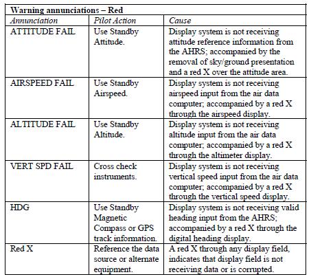
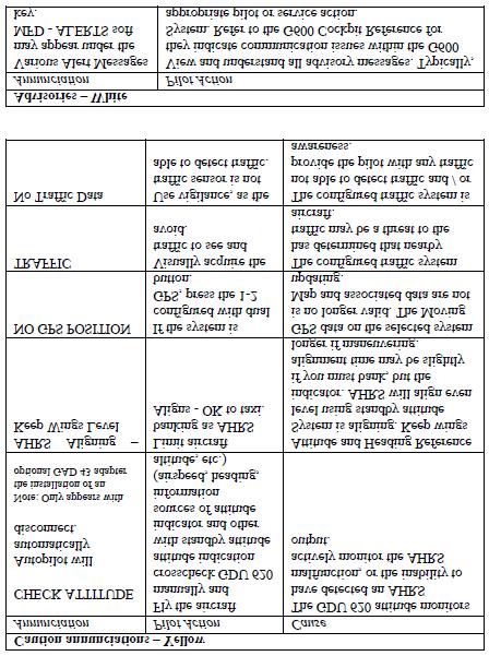
30 GARMIN G500 ABNORMAL INDICATIONS Heading Failure A magnetometer failure is indicated by a HDG with a red X over it just to the left of the heading display. If the GDU 620 is still receiving valid GPS ground track from the GNS navigator, the heading will be replaced with GPS ground track in magenta. The aircraft can be flown by reference to GPS ground track instead of heading. In this case, the autopilot will continue to fly in HDG mode, but the course being sent to the autopilot will be based on ground track instead of magnetic heading. A complete Heading Failure (magnetometer and GPS ground track failure) is indicated by the digital heading presentation being replaced with a red X and the compass rose digits being removed. The course pointer will indicate straight up and operate much like a traditional CDI with the Omni-Bearing Selector being adjusted by the PFD knob set to CRS. Under this condition, the pilot must use an alternate source of heading such as the standby compass. If the installation includes an autopilot, the pilot workload may be reduced by operating that system in NAV mode. AHRS Failure A failure of the Attitude and Heading Reference System (AHRS) is indicated by a removal of the sky/ground presentation, a red X, and a yellow AHRS FAILURE shown on the PFD. A heading failure will also occur as described above in Use Standby Attitude Indicator and standby compass 2. Set course datum using CRS selection of the PFD knob 3. Seek VFR conditions or land as soon as practical Air Data Computer (ADC) Failure Complete loss of the Air Data Computer is indicated by a red X and yellow text over the airspeed, altimeter, vertical speed, TAS and OAT displays. Some derived functions, such as true airspeed and wind calculations, will also be lost. 1. Use Standby Airspeed Indicator and Altimeter 2. Seek VFR conditions or land as soon as practical 3-30
31 Loss of Electrical Power In the event of a total loss of electrical power, the G500 system will cease to operate and the pilot must utilize the standby instruments to fly the aircraft. For installations utilizing the battery powered electric attitude gyro, the amber standby power light will start flashing. Press the STBY PWR button to operate the gyro via its emergency battery. If the red warning flag is in view, the gyro is inoperative and must not be used. WARNINGS, CAUTIONS, AND ADVISORIES The following tables show the color and significance of the warning, caution, and advisory messages which may appear on the G500 displays. NOTE The G500 Cockpit Reference Guide and the G500 Pilot s Guide contain detailed descriptions of the annunciator system and all warnings, cautions and advisories. 3-31
32 . 3-32
33 3-33
AIRSPEEDS. Cessna 172R Emergency Checklist
 AIRSPEEDS AIRSPEEDS FOR EMERGENCY OPERATION Cessna 172R Emergency Checklist INTRODUCTION This document provides checklist and amplified procedures for coping with emergencies that may occur. Emergencies
SECTION 3 EMERGENCY PROCEDURES
 FOUND SECTION 3 300HP SECTION 3 TABLE OF CONTENTS Page Introduction... 3-3 Airspeeds for Emergency Operation... 3-5 CHECKLISTS Engine Failures... 3-6 Engine Failure During Takeoff Run... 3-6 Engine Failure
CESSNA 182 CHECKLIST. LEFT WING Trailing Edge 1. Aileron CHECK freedom of movement and security
 CESSNA 182 CHECKLIST PRE-FLIGHT INSPECTION CABIN 1. Pilot s Operating Handbook AVAILABLE IN THE AIRPLANE (A.R.R.O.W.E) 2. Landing Gear Lever DOWN 3. Control Wheel Lock REMOVE 4. Ignition Switch OFF 5.
Preflight Inspection Cabin EMPENNAGE RIGHT WING Trailing Edge RIGHT WING NOSE
 Preflight Inspection Cabin 1. Control Wheel Lock REMOVED 2. Ignition Switch OFF 3. Avionics Power Switch OFF 4. Master Switch ON 5. Fuel Quantity Indicators CHECK QUANTITY 6. Master Switch OFF 7. Fuel
INDEX: Normal Procedures Emergency Procedures Pre Flight Inspection NORMAL PROCEDURES BEFORE STARTING ENGINE
 INDEX: Normal Procedures Emergency Procedures Pre Flight Inspection NORMAL PROCEDURES BEFORE STARTING ENGINE 1. Preflight Inspection -- COMPLETE 2. Seats, Belts, Shoulder Harnesses -- ADJUST and LOCK 3.
Interior Pre Flight Documents: Check Control Wheel Lock: Remove Flight Controls: Check Instruments: Check for Damage Switches: Verify All Off Master
 Interior Pre Flight Documents: Check Control Wheel Lock: Remove Flight Controls: Check Instruments: Check for Damage Switches: Verify All Off Master Switch ALT/BAT: On Fuel Gauge: Check Quantity Flaps:
Owners Manual. Table of Contents 3.1. INTRODUCTION AIRSPEEDS FOR EMERGENCY OPERATION OPERATIONAL CHECKLISTS 3
 EMERGENCY PROCEDURES Table of Contents 3.1. INTRODUCTION 2 3.2. AIRSPEEDS FOR EMERGENCY OPERATION 2 3.3. OPERATIONAL CHECKLISTS 3 3.3.1. ENGINE FAILURES 3. ENGINE FAILURE DURING TAKEOFF RUN 3. ENGINE FAILURE
EMERGENCY PROCEDURES TABLE OF CONTENTS
 CESSNA SECTION 3 TABLE OF CONTENTS Page Introduction............................................3-5 Airspeeds For Emergency Operations........................3-5.........................3-6 ENGINE FAILURES.....................................3-6
COLUMBIA 350 EMERGENCY PROCEDURES
 COLUMBIA 350 EMERGENCY PROCEDURES TABLE OF CONTENTS EMERGENCY PROCEDURES LANDING AND TAKEOFF Engine Failure During Takeoff...1 Engine Failure Immediately After Takeoff...1 Engine Failure During Climb to
Cessna 182S-CHECKLIST PROCEDURES
 Cessna 182S-CHECKLIST PROCEDURES PREFLIGHT INSPECTION 1 CABIN 1. Pitot Tube Cover -- REMOVE (if installed) and check for stoppage 2. Pilot s Operating Handbook AVAILABLE IN THE AIRPLANE 3. Airplane Weight
AIRSPEEDS FOR EMERGENCY OPERATIONS
 INTRODUCTION Section 3 provides checklist and amplified procedures for coping with emergencies that may occur. Emergencies caused by airplane or engine malfunctions are extremely rare if proper preflight
S A F E T Y NORMAL PROCEDURES NORMAL PROCEDURES BEFORE STARTING ENGINE PASSENGER SAFETY BRIEFING STARTING ENGINE
 PRE-FLIGHT PRE-FLIGHT BEFORE STARTING ENGINE PASSENGER SAFETY BRIEFING 1. Preflight Inspection COMPLETE 2. Passenger Safety Briefing COMPLETE 3. Seats, Belts, Shoulder Harnesses ADJUST AND LOCK 4. Fuel
CESSNA 172I CESSNA 172I PREFLIGHT INSPECTION
 PREFLIGHT INSPECTION Visually check airplane for general condition during walk-around inspection. In cold weather, remove even small accumulations of frost, ice or snow from wing, tail and control surfaces.
EMERGENCY CHECKLIST for N11HC
 OFF AIRPORT LANDING Airspeed / AOA... Vg (2G-1Y ~85 K) Best Field... Into Wind 3 Power Knobs... Aft Fuel Selector... Off Flaps... As Required Slip... As Required Mags... Off Talk... Emergency Squawk...
CESSNA 172N 08E/97E CESSNA 172N 08E/97E PREFLIGHT INSPECTION
 PREFLIGHT INSPECTION Visually check airplane for general condition during walk-around inspection. In cold weather, remove even small accumulations of frost, ice or snow from wing, tail and control surfaces.
Vso 61. Vs1 63. Vr 70. Vx 76. Vxse 78. Vy 89. Vyse. 89 (blue line) Vmc. 61 (radial redline) Vsse 76. Va 134) Vno 163
 Vmc. 61 (radial redline) Vsse 76. Va 134) Vno 163") PA34-200T Piper Seneca II Normal procedures V-speeds Knots Vso 6 Vs 63 Vr 70 Vx 76 Vxse 78 Vy 89 Vyse Vmc 89 (blue line) 6 (radial redline) Vsse 76 Va 2-36(@4507lbs 34) Vno 63 Vfe 38 (0*)/2(25*)/07(40*)
PA34-200T Piper Seneca II Normal procedures V-speeds Knots Vso 6 Vs 63 Vr 70 Vx 76 Vxse 78 Vy 89 Vyse Vmc 89 (blue line) 6 (radial redline) Vsse 76 Va 2-36(@4507lbs 34) Vno 63 Vfe 38 (0*)/2(25*)/07(40*)
V - Speeds. RV-10 V fe Flaps Speeds Trail (0 deg) Half (15 deg) Full (30 deg) 122 kias 96 kias. 80 kias
 Half (15 deg) Full (30 deg) 122 kias 96 kias. 80 kias") RV-10 Check List V - Speeds RV-10 V fe Flaps Speeds Trail (0 deg) Half (15 deg) Full (30 deg) 122 kias 96 kias 87 kias V s1 Stall (Flap Up) 60 kias V s0 Stall (Flap 40 deg) 55 kias Best Glide 80 kias V
RV-10 Check List V - Speeds RV-10 V fe Flaps Speeds Trail (0 deg) Half (15 deg) Full (30 deg) 122 kias 96 kias 87 kias V s1 Stall (Flap Up) 60 kias V s0 Stall (Flap 40 deg) 55 kias Best Glide 80 kias V
Cessna 152 Checklist
 Cessna 152 Checklist This checklist covers the operation of the model 152. Use at your own risk, the author nor the publisher is responsible for any damage or accidents resulting from the use of this checklist.
Cessna 172 Skyhawk. Aircraft Checklist Models: R & S
 Cessna 172 Skyhawk Aircraft Checklist Models: R & S This is an abbreviated checklist. Most explanatory items, notes cautions and warnings have been omitted for brevity. Procedures in red/bold text in this
CARENADO COPYRIGHTS. Normal & Emergency Checklist
 NORMAL PROCEDURES CHECKLIST PREFLIGHT CHECK Control wheel -- RELEASE BELTS Avionics -- OFF Master Switch -- ON Fuel quantity gauges -- CHECK Master switch -- OFF Ignition -- OFF Exterior -- CHECK FOR DAMAGE
CESSNA SECTION 4. Unless otherwise noted, the following speeds are based on a maximum weight of 2550 pounds and may be used for any lesser weight.
 CESSNA SECTION 4 INTRODUCTION Section 4 provides procedures and amplified instructions for normal operations using standard equipment. Normal procedures associated with optional systems can be found in
TECNAM P2004 BRAVO N128LS
 TECNAM P2004 BRAVO N128LS GENERAL INFORMATION NORMAL PROCEDURES TIME SENSITIVE EMERGENCY TECNAM P2004 BRAVO CHECKLIST [FLIGHT PLAN DESIGNATION IS BRAV ] EMERGENCY CONTACT The following are First Landings'
Aircraft Checklist Cessna 182T
 Aircraft Checklist Cessna 182T This is an abbreviated checklist. Most explanatory items, notes cautions and warnings have been omitted for brevity. Procedures in red/bold in this checklist should be committed
N123AX Piper Saratoga II HP (PA-32R-301) Checklist (v23 - Revision 3 April 2011) AIRSPEEDS FOR SAFE OPERATIONS. Best Rate of Climb (gear up, flaps up)
 Checklist (v23 - Revision 3 April 2011) AIRSPEEDS FOR SAFE OPERATIONS. Best Rate of Climb (gear up, flaps up)") N123AX Piper Saratoga II HP (PA-32R-301) Checklist (v23 - Revision 3 April 2011) AIRSPEEDS FOR SAFE OPERATIS Best Rate of Climb (gear down, flaps up) Best Rate of Climb (gear up, flaps up) Turbulent Air
N123AX Piper Saratoga II HP (PA-32R-301) Checklist (v23 - Revision 3 April 2011) AIRSPEEDS FOR SAFE OPERATIS Best Rate of Climb (gear down, flaps up) Best Rate of Climb (gear up, flaps up) Turbulent Air
INDEX. Preflight Inspection Pages 2-4. Start Up.. Page 5. Take Off. Page 6. Approach to Landing. Pages 7-8. Emergency Procedures..
 INDEX Preflight Inspection Pages 2-4 Start Up.. Page 5 Take Off. Page 6 Approach to Landing. Pages 7-8 Emergency Procedures.. Page 9 Engine Failure Pages 10-13 Propeller Governor Failure Page 14 Fire.
NORMAL CHECKLIST ATTENTION!
 Avion Training CHECKLIST Normal Checklist CESSNA 172R / TC-STS Cessna 172 R TC-STS NORMAL CHECKLIST ATTENTION! DO NOT STOW THIS CHECKLIST IN DIRECT SUNLIGHT Avion Training - Doc.nr. 212 Revision 1 / 02022018
TECNAM P92 EAGLET N615TA TECNAM P92 EAGLET CHECKLIST [FLIGHT PLAN DESIGNATION IS ECHO ]
![TECNAM P92 EAGLET N615TA TECNAM P92 EAGLET CHECKLIST [FLIGHT PLAN DESIGNATION IS ECHO ]](/thumbs/86/93080937.jpg "TECNAM P92 EAGLET N615TA TECNAM P92 EAGLET CHECKLIST [FLIGHT PLAN DESIGNATION IS ECHO ]") TECNAM P92 EAGLET CHECKLIST [FLIGHT PLAN DESIGNATION IS ECHO ] EMERGENCY CONTACT The following are First Landings' emergency contact telephone numbers. We ask that you call the numbers in the order listed.
TECNAM P92 EAGLET CHECKLIST [FLIGHT PLAN DESIGNATION IS ECHO ] EMERGENCY CONTACT The following are First Landings' emergency contact telephone numbers. We ask that you call the numbers in the order listed.
Aircraft Checklist Commander 114
 Aircraft Checklist Commander 114 This is an abbreviated checklist. Most explanatory items, notes cautions and warnings have been omitted for brevity. Procedures in red/bold text in this checklist should
Cessna 172P PPL Checklist Page 1
 Cessna 172P PPL Checklist 06-08-2017 Page 1 Cessna 172P PPL Checklist 06-08-2017 Page 2 Checklist Items Informational Items Critical Memory Items PREFLIGHT COCKPIT CHECK (DO-LIST) Pitot Cover -- REMOVE
Jump to Table of Contents
 Jump to Table of Contents PIPER AIRCRAFT CORPORATION PA-28R-201, CHEROKEE ARROW III SECTION 3 EMERGENCY PROCEDURES 3.3 EMERGENCY PROCEDURES CHECK LIST ENGINE FIRE DURING
Tie down IAS-TAS Table 14
 PA28-161- 1 Piper PA28-161 Archer II Cockpit Interior Exterior Check Exterior Check [cont.] Before Start Engine Start After Start ENG Flooded Start Start with External Pwr Run-Up Before Takeoff Short Field
Piper Archer II (PA )
") 1. Oil... 6-8 qts, Cap Secure CABIN 1. POH & Documents.. Check Available 2. Magneto Switch...... OFF 3. Pitot/Static Drains... Push to Drain 4. Avionics/Electrical Switches... OFF 5. Master Switch. ON
1. Oil... 6-8 qts, Cap Secure CABIN 1. POH & Documents.. Check Available 2. Magneto Switch...... OFF 3. Pitot/Static Drains... Push to Drain 4. Avionics/Electrical Switches... OFF 5. Master Switch. ON
Elmendorf Aero Club Aircraft Test
 DO NOT WRITE ON THIS TEST FEB 2013 Elmendorf Aero Club Aircraft Test Cessna - 172 For the following questions, you will need to refer to the Pilots Information Manual for the C-172R (180hp). The bonus
If, nonetheless, an emergency does arise, the guidelines given here should be followed and applied in order to clear the problem.
 3.1 INTRODUCTION 3.1.1 GENERAL This Chapter contains checklists as well as the description of recommended procedures to be followed in the event of an emergency. Engine failure or other airplane-related
The engines are designed to use 100/130 octane fuel. If not available use next higher grade. - 1
 PNEUMATIC SYSTEM The aircraft has a dual pneumatic system. In case of failure of either pneumatic pump, the system will automatically select the operative source. (Inoperative source will be indicated
CHECKLIST N8876B Cessna 172. Nebraska Flight Center Eppley Airfield 3737 Orville Plaza Omaha, NE Tel. (402)
") CHECKLIST N8876B 1958 Cessna 172 F Nebraska Flight Center Eppley Airfield 3737 Orville Plaza Omaha, NE 68110 Tel. (402) 342-4314 www.nebflight.com Cessna 172 N8876B 1958 GENERAL INFORMATION Model... Cessna
CHECKLIST N8876B 1958 Cessna 172 F Nebraska Flight Center Eppley Airfield 3737 Orville Plaza Omaha, NE 68110 Tel. (402) 342-4314 www.nebflight.com Cessna 172 N8876B 1958 GENERAL INFORMATION Model... Cessna
Best Glide 75 kias (Max Gross)
") CESSNA 172XP CHECKLIST PREFLIGHT (Interior) 1. ACFT DOCS / INSPECTIONS--------CHECK 2. TACH TIME-----------------------------RECORD 3. CONTROL LOCK---------------------REMOVE 4. ELEVATOR / RUDDER TRIM------------
CESSNA 172XP CHECKLIST PREFLIGHT (Interior) 1. ACFT DOCS / INSPECTIONS--------CHECK 2. TACH TIME-----------------------------RECORD 3. CONTROL LOCK---------------------REMOVE 4. ELEVATOR / RUDDER TRIM------------
SECTION 3 EMERGENCY PROCEDURES
 SECTION 3 EMERGENCY PROCEDURES EMERGENCY PROCEDURES TABLE OF CONTENTS Introduction... 3 Airspeeds For Emergency Operations... 3 Ground Emergencies... 4 Engine Fire during Start... 4 Engine Failure during
DO NOT WRITE ON THIS TEST FEB 2013 Elmendorf Aero Club Aircraft Test. Cessna - 182
 DO NOT WRITE ON THIS TEST FEB 2013 Elmendorf Aero Club Aircraft Test Cessna - 182 For the following questions, you will need to refer to the Pilots Information Manual for the C-182R. The bonus questions
PA32-RT LANCE II CHECKLIST
 PA32-RT LANCE II CHECKLIST 6815.10.1112 1 Normal Procedures PREFLIGHT CHECK Control Wheel... RELEASE BELTS Parking brake... Set Master Switch... ON Fuel Quantity Gauges... check Master Switch... OFF Ignition...
SECTION 3 EMERGENCY PROCEDURES
 Liberty Aerospace, Inc. Section 3 SECTION 3 TABLE OF CONTENTS Introduction...3-3 Airspeeds for Emergency Operations...3-3 Ground Emergencies...3-4 Engine Fire During Start...3-4 Engine Failure During Takeoff
Elmendorf Aero Club Aircraft Test
 DO NOT WRITE ON THIS TEST FEB 2013 Elmendorf Aero Club Aircraft Test Cessna - 182 For the following questions, you will need to refer to the Pilots Information Manual for the C-182R. The bonus questions
N1523J CHECKLIST PA Nebraska Flight Center Eppley Airfield 3737 Orville Plaza Omaha, NE Tel. (402)
") CHECKLIST N1523J 1967 Cherokee 140 PA-28-140 F Nebraska Flight Center Eppley Airfield 3737 Orville Plaza Omaha, NE 68110 Tel. (402) 342-4314 www.nebflight.com Piper Cherokee 140 N1523J 1967 GENERAL INFORMATION
CHECKLIST N1523J 1967 Cherokee 140 PA-28-140 F Nebraska Flight Center Eppley Airfield 3737 Orville Plaza Omaha, NE 68110 Tel. (402) 342-4314 www.nebflight.com Piper Cherokee 140 N1523J 1967 GENERAL INFORMATION
CESSNA 172S NAV III VFR CHECKOUT POH EXAMINATION (Based on N1129K, serial no. 172S revised 10/05/06)
") INTRODUCTION, POH CESSNA 172S NAV III VFR CHECKOUT POH EXAMINATION (Based on N1129K, serial no. 172S10315 - revised 10/05/06) 1. Rate of climb at sea level: 2. Service ceiling: 3. Takeoff performance,
INTRODUCTION, POH CESSNA 172S NAV III VFR CHECKOUT POH EXAMINATION (Based on N1129K, serial no. 172S10315 - revised 10/05/06) 1. Rate of climb at sea level: 2. Service ceiling: 3. Takeoff performance,
Elmendorf Aero Club Aircraft Test
 DO NOT WRITE ON THIS TEST FEB 2014 Elmendorf Aero Club Aircraft Test Cessna - 185 For the following questions, you will need to refer to the Pilots Information Manual for the C-185F and Graphic Engine
CHECKLIST 1969 CESSNA 172-K. NOTE: Verify all information with airplane's POH
 CHECKLIST 1969 CESSNA 172-K NOTE: Verify all information with airplane's POH PRE-FLIGHT INSPECTION 1 CABIN 1 A.R.R.O.W. CHECK Airworthiness Cert. In Clear View Registration In Clear View Radio License
OPERATIONS MANUAL FTO SECTION : 06.04
 06.04.08. OO-WIK SECTION : 06.04 PARTENAVIA OO-WIK PAGE : 1 PRE ENTRY PITOT COVER - REMOVE SNOW / ICE CHECK AIRCRAFT NOSE INTO WIND AIRCRAFT WEIGHT & BALANCE WITHIN LIMITS EXTERNAL (COCKPIT FIRST) PARK
PA , Model E Normal Checklist (04/15/11)
") PA-23-250, Model E Normal Checklist (04/15/11) Key Airspeeds IAS-MPH V NE 249 V NO 198 V LO/LE 150 V A (At max gross weight.) 149 Speed for single engine cruise. 138 V FE Quarter Flaps 160 Half Flaps 140
PA-23-250, Model E Normal Checklist (04/15/11) Key Airspeeds IAS-MPH V NE 249 V NO 198 V LO/LE 150 V A (At max gross weight.) 149 Speed for single engine cruise. 138 V FE Quarter Flaps 160 Half Flaps 140
NORMAL PROCEDURRES CHECKLIST PA T SENECA II PREFLIGHT CHECK INSIDE CABIN OUTSIDE CABIN
 NORMAL PROCEDURRES CHECKLIST PA-34-200T SENECA II PREFLIGHT CHECK INSIDE CABIN Avionics Master Switch -- OFF Landing Gear Control. -- DOWN Mixture Controls -- IDLE/CUTOFF Ignition Switches -- OFF Master
PA28R ARROW CHECKLIST
 PA28R ARROW CHECKLIST 2300.11.0112 1 Normal Procedures Initial PREFLIGHT CHECK General Appearance... CHECKED Position & Taxi Path... CHECKED Tie Downs, Locks, Chocks & Covers... REMOVED Cockpit Controls...UNLOCKED
QUICK REFERENCE HANDBOOK TECNAM P92 ECHO
 NORMAL LISTS PRE-START S Park brake Left fuel cock Flight Instruments (No broken glass or bent needles) Engine Instruments (No broken glass or bent needles) Right fuel cock Fuses Landing Light Avionics
Van s Aircraft RV-7A. Pilot s Operating Handbook N585RV
 Van s Aircraft RV-7A Pilot s Operating Handbook N585RV PERFORMANCE SPECIFICATIONS SPAN:..25 0 LENGTH...20 4 HEIGHT:.. 7 10 SPEED: Maximum at Sea Level...180 knots Cruise, 75% Power at 8,000 Ft...170 knots
PA GURW (December 30, 2000) PRE-START. Langley Flying School. Airspeeds (MPH) for Safe Operation. Cockpit Checks
 PRE-START. Langley Flying School. Airspeeds (MPH) for Safe Operation. Cockpit Checks") Langley Flying School PA-34-200 GURW (December 30, 2000) Airspeeds (MPH) for Safe Operation V y (all weights) 105 V x (all weights) 90 En Route Climb 120 V mc 80 V yse 105 V xse 93 V r 80 V r (25 Flaps)
Langley Flying School PA-34-200 GURW (December 30, 2000) Airspeeds (MPH) for Safe Operation V y (all weights) 105 V x (all weights) 90 En Route Climb 120 V mc 80 V yse 105 V xse 93 V r 80 V r (25 Flaps)
PA-28R 201 Piper Arrow
 Beale Aero Club Aircraft Written Test PA-28R 201 Piper Arrow (Required passing score: 80%) 1. If an engine power loss occurs immediately after take off, the pilot s reaction should be to: a. maintain safe
Flight Checklist for Normal Operations Massgebend ist das AFM (Parameters, Restrictions, Emergency, etc.)
") Flight Checklist for Normal Operations Massgebend ist das AFM (Parameters, Restrictions, Emergency, etc.) Jan18 1 COCKPIT PREPARATION BEFORE STARTING ENGINE 1 Aircraft + Cockpit Inspection COMPLETED 1
Flight Checklist for Normal Operations Massgebend ist das AFM (Parameters, Restrictions, Emergency, etc.) Jan18 1 COCKPIT PREPARATION BEFORE STARTING ENGINE 1 Aircraft + Cockpit Inspection COMPLETED 1
Flight checklist for normal operations Massgebend ist das AFM (parameters, restrictions, emergency, etc.)
") JAN13 1 Flight checklist for normal operations Massgebend ist das AFM (parameters, restrictions, emergency, etc.) Cockpit preparation before starting engine 1 Aircraft + Cockpit inspection completed (according
JAN13 1 Flight checklist for normal operations Massgebend ist das AFM (parameters, restrictions, emergency, etc.) Cockpit preparation before starting engine 1 Aircraft + Cockpit inspection completed (according
FAA APPROVED AIRPLANE FLIGHT MANUAL SUPPLEMENT DOCUMENT NUMBER FOR CESSNA 172R S/N REG.
 AIR PLAINS FAA APPROVED AIRPLANE FLIGHT MANUAL SUPPLEMENT DOCUMENT NUMBER 172059 FOR CESSNA 172R S/N REG. This supplement must be attached to the FAA Approved Airplane Flight Manual when STC SA2196CE,
Pilot's Operating Handbook Supplement AS-03
 POH / AFM SECTION 9 Pilot's Operating Handbook Supplement ASPEN EFD1000 PFD This supplement is applicable and must be inserted into Section 9 of the POH when the Aspen Avionics Evolution Flight Display
CHAPTER 7 ABNORMAL FLOWS AND CHECKLISTS TABLE OF CONTENTS
 CHAPTER 7 ABNORMAL FLOWS AND CHECKLISTS TABLE OF CONTENTS ELECTRICAL FAULTS...3 Alternator Failure / Low Voltage...3 INSTRUMENTS...7 Low vacuum indication / vacuum failure...7 Erroneous airspeed / altitude
Com Active/Standby Frequency Switch. C om Active/Standby Frequencies. Terrain. Flight Plan. Button. Button
 ALABEO GNS530 Nav Active/Standby Frequency Switch Com Active/Standby Frequency Switch C om Active/Standby Frequencies Zoom In/Out Button Nav Active/Standby Frequencies On/Off Button Direct To Button Nav1
Cessna 172S Skyhawk. AFTER LANDING CHECK RPM CHECK 2. Flaps UP 3. Transponder STANDBY 4. Strobes OFF 5. Contact Ground as Required. 121.
 PRE-LANDING CHECK 1. ATIS/AWOS/ASOS OBTAIN 2. Seat Belts CHECK 3. Autopilot OFF 4. Master Switch ON 5. Ignition BOTH 6. Circuit Breakers ALL IN 7. Landing Light AS REQ. 8. Mixture (Push) RICH 9. Fuel Selector
PA ARCHER II Quick Reference Handbook
 PA28-180 ARCHER II Quick Reference Handbook ALL GREY SHADED AREAS ARE MEMORY ITEMS 7813.03.0116 1 Table of Contents Normal Procedures... 4 PREFLIGHT CHECK... 4 BEFORE START... 6 FLOODED ENGINE START...
EMERGENCY PROCEDURES ENGINE FIRE DURING START/GROUND OPERATIONS STARTER ENERGIZED ANNUNCIATOR ILLUMINATED. Memory items are printed in red.
 ENG FIRE-GRND, STARTER ENERGIZED EMERGENCY PROCEDURES Memory items are printed in red. ENGINE FIRE DURING START/GROUND OPERATIONS 1. Mixture...IDLE CUTOFF 2. Fuel Selector Valve... OFF 3. Battery, Alternator,
AIRPLANE FLIGHT MANUAL AQUILA AT01 AIRPLANE FLIGHT MANUAL - SUPPLEMENT AVE28 GLASS COCKPIT. equipped with ASPEN EFD1000 PFD
 SECTION 9 AIRPLANE FLIGHT MANUAL - SUPPLEMENT AVE28 GLASS COCKPIT equipped with ASPEN EFD1000 PFD This AFM supplement is applicable and must be inserted into Section 9 of the Airplane Flight Manual when
Checklist for Bellanca Viking N4880V (Speeds in MPH (KTS) IAS)
 IAS)") V-SPEEDS Checklist for Bellanca Viking N4880V V SO 62 (54) Stall Full Flaps V S1 72 (63) Stall Clean V R 80 (70) Takeoff Rotation Flaps Up V Y 110 (96) Best Rate Gear Up & Flaps Up V R 70 (61) Takeoff
V-SPEEDS Checklist for Bellanca Viking N4880V V SO 62 (54) Stall Full Flaps V S1 72 (63) Stall Clean V R 80 (70) Takeoff Rotation Flaps Up V Y 110 (96) Best Rate Gear Up & Flaps Up V R 70 (61) Takeoff
Pilot s Checklist PIPER ARROW PA-28R-201
 Pilot s Checklist PIPER ARROW PA-28R-201 Original Issue 10/31/2012 REVISIONS Changes and/or additions in this checklist will be covered by Owner Advisories published by the Piper Aircraft Corporation.
Cessna 172RG WARNING. Maximum Demonstrated Crosswind. Takeoff or landing..15 KTS
 Cessna 172RG INTRODUCTION: This aircraft checklist contains information from the original manufacturer s Pilot Information Manual. Normal procedures associated with optional systems can be found in Section
USAF Aero Club T-41B (Cessna R-172E) Aircraft Exam Updated February 2017
 Aircraft Exam Updated February 2017") USAF Aero Club T-41B (Cessna R-172E) Aircraft Exam Updated February 2017 Instructions Complete the supplement following exam using the answer sheet provided. Do not assume information not specifically
USAF Aero Club T-41B (Cessna R-172E) Aircraft Exam Updated February 2017 Instructions Complete the supplement following exam using the answer sheet provided. Do not assume information not specifically
PA WARRIOR II Quick Reference Handbook
 PA28-161 WARRIOR II Quick Reference Handbook Version 1.0 ALL GREY SHADED AREAS ARE MEMORY ITEMS Normal Procedures Pre-Flight Check... N-1 Before Start... N-3 Flooded Engine Start... N-4 Starting With
I. DISPATCH PLANNING & AIRCRAFT EXTERIOR CHECK
 SCHODACK AVIATION Page 1 of 10 I. DISPATCH PLANNING & AIRCRAFT EXTERIOR CHECK 1. Flight Planning 1. Aircraft requirements & preparation: Required aircraft documents: Airworthiness Certificate Registration
a. Lycoming IO-520J 250 HP c. Lycoming O-540-J3C5D 235 HP b. Continental O450T 330 HP d. Lycoming O-360A 180 HP
 Three points each question Page 1 of 6 References: Pilot's Operating Handbook for the 1979 Cessna R182 Model; Flying Magazine Article "Cessna 182 Safety Report;" RAFA SOP; and Refueling Instructions found
NORMAL (Vy) CLIMB 1. Set pitch for 88 KIAS (-1.4 kt per 1,000 MSL) 2. Power - 23 Hg and 2400 rpm 3. Mixture - lean above 3,000 MSL
 CLIMB 1. Set pitch for 88 KIAS (-1.4 kt per 1,000 MSL) 2. Power - 23 Hg and 2400 rpm 3. Mixture - lean above 3,000 MSL") BEFORE EXTERIOR INSPECTION P. 1 1. Remove tie-downs (if secured by tie-downs) 2. Landing gear lever - Down 3. Control wheel lock - Removed/stowed 4. Ignition switch - Off 5. Avionics power switch - Off
BEFORE EXTERIOR INSPECTION P. 1 1. Remove tie-downs (if secured by tie-downs) 2. Landing gear lever - Down 3. Control wheel lock - Removed/stowed 4. Ignition switch - Off 5. Avionics power switch - Off
FLASHCARDS AIRCRAFT. Courtesy of the Air Safety Institute, a Division of the AOPA Foundation, and made possible by AOPA Services Corporation.
 AIRCRAFT FLASHCARDS Courtesy of the Air Safety Institute, a Division of the AOPA Foundation, and made possible by AOPA Services Corporation. Knowing your aircraft well is essential to safe flying. These
I. DISPATCH PLANNING & AIRCRAFT EXTERIOR CHECK
 SCHODACK AVIATION Page 1 of 10 I. DISPATCH PLANNING & AIRCRAFT EXTERIOR CHECK 1. Flight Planning 1. Aircraft requirements & preparation: 1. Required aircraft documents: 1. Airworthiness Certificate 2.
GACE Flying Club Aircraft Review Test 2018 N5312S & N5928E. Name: GACE #: Score: Checked by: CFI #:
 GACE Flying Club Aircraft Review Test 2018 N5312S & N5928E Name: GACE #: Score: Checked by: CFI #: Date: (The majority of these questions are for N5312S. All N5928E questions will be marked 28E) 1. What
Elmendorf Aero Club Aircraft Test
 DO NOT WRITE ON THIS TEST JAN 2014 Elmendorf Aero Club Aircraft Test SENECA II For the following questions, you will need to refer to the Pilots Information Manual for the PA-34-200T. USE ANSWER SHEET
Checklist LN-DAG SFK 2014
 Checklist LN-DAG SFK 2014 2 GROUND Exsterior Checklist 1. Fuel (wings & filter) - Drained 2. Documents - Checked 3. Fire extinguisher, first aid sur. kit - Checked 4. Magnetos - Off 5. Master switch -
Wings of Carolina Flying Club PA Aircraft Type Checkout and Currency Quiz
 Wings of Carolina Flying Club PA-28-161 Aircraft Type Checkout and Currency Quiz Pilot Instructor Score Date Instructor: Please note the final score (subtract 2.5 points from 100 for each wrong answer)
PREFLIGHT CHECK COCKPIT RIGHT WING. NORMAL PROCEDURRES CHECKLIST PA-28RT 201 Arrow IV
 NORMAL PROCEDURRES CHECKLIST PA-28RT 201 Arrow IV PREFLIGHT CHECK COCKPIT Control Wheel -- Release Restraints Avionics -- OFF Parking Brake -- SET All Switches -- OFF Mixture -- IDLE CUT-OFF Master Switch
Expanded Flight Checklist Cessna 152
 OUTSIDE CHECK INSIDE CABIN 1 Magnetos... OFF 2 Mixture... IDLE CUT OFF 3 Master switch... ON 4 Fuel quantity... CHECKED 5 Master switch... OFF OUTSIDE CABIN 1 Left wing... CHECKED Surface condition Flap
2010 Airborne Aviation Pty Ltd
 Aircraft Information Booklet Pitts S-2C VH-JAX Last revised: 10 September 2010 2010 Airborne Aviation Pty Ltd www.airborne-aviation.com.au THIS PAGE INTENTIONALLY LEFT BLANK Contents Aircraft Overview
N8503. BELLANCA CITABRIA Model 7ECA. Checklist EMERGENCY PROCEDURES - ELECTRICAL. Ver. July 2 nd,
 EMERGENCY PROCEDURES - ELECTRICAL ALTERNATOR/ELECTRICAL FAILURE An alternator failure is indicated by a steady discharge on the ammeter. 1) Master switch CYCLE in attempt to reset the over-voltage relay
SECTION IV NORMAL PROCEDURES TABLE OF CONTENTS
 SECTION IV NORMAL PROCEDURES TABLE OF CONTENTS SUBJECT PAGE Speeds for Safe Operation 4-3 Preflight Inspection 4-4 Before Starting 4-5 External Power 4-6 Starting Engine Using Auxiliary Power Unit. 4-7
CHECKLIST FOR NORMAL OPERATION PIPER P32R
 FLUGSCHULE GRENCHEN CHECKLIST Piper Saratoga SP 1 CHECKLIST FOR NORMAL OPERATION PIPER P32R Parameters, restrictions, procedures and emergency procedures see AFM BEFORE FIRST FLIGHT 1. Aircraft & Cockpit
Cessna Aircraft Short & Soft Field Takeoff & Landing Techniques
 Cessna Aircraft Short & Soft Field Takeoff & Landing Techniques Objectives / Content For short- and soft-field takeoff and landing operations in CAP Cessna aircraft, review: Standards (from ACS) Procedures
LOG OF REVISIONS. Model G58 Baron (Serials TH-2125 and After) Pilot s Operating Handbook and FAA Approved Airplane Flight Manual
 Pilot s Operating Handbook and FAA Approved Airplane Flight Manual") LOG OF REVISIONS Model G58 Baron (Serials TH-2125 and After) Pilot s Operating Handbook and FAA Approved Airplane Flight Manual Revision A12 - May, 2015 Title Page LOEP LOR Section 1 All Reformatted to
LOG OF REVISIONS Model G58 Baron (Serials TH-2125 and After) Pilot s Operating Handbook and FAA Approved Airplane Flight Manual Revision A12 - May, 2015 Title Page LOEP LOR Section 1 All Reformatted to
RFC Dallas, Inc. AIRCRAFT QUESTIONNAIRE (9/25/2016) "A Safe Pilot Knows His Equipment"
 A Safe Pilot Knows His Equipment") RFC Dallas, Inc. AIRCRAFT QUESTIONNAIRE (9/25/2016) "A Safe Pilot Knows His Equipment" NAME: Date: Aircraft: Cessna 182Q Registration Number: N631S Serial Number: The purpose of this questionnaire is to
RFC Dallas, Inc. AIRCRAFT QUESTIONNAIRE (9/25/2016) "A Safe Pilot Knows His Equipment" NAME: Date: Aircraft: Cessna 182Q Registration Number: N631S Serial Number: The purpose of this questionnaire is to
Checklist Robin DR40
 Flight Checklist for Normal Operations Massgebend ist das AFM (Parameters, Restrictions, Emergency, etc.) Jan 18 1 COCKPIT PREPARATION BEFORE STARTING ENGINE 1 Aircraft + Cockpit Inspection COMPLETED 1
SECTION 9 SUPPLEMENTS
 ROBINSON MODEL R44 II SECTION 9 SUPPLEMENTS SECTION 9 SUPPLEMENTS OPTIONAL EQUIPMENT SUPPLEMENTS Information contained in the following supplements applies only when the related equipment is installed.
CESSNA 182 TRAINING MANUAL. Trim Control Connections
 Trim Control Connections by D. Bruckert & O. Roud 2006 Page 36 Flaps The flaps are constructed basically the same as the ailerons with the exception of the balance weights and the addition of a formed
~" -~lrcraft Certification Office Federal Aviation Administration Wichita, Kansas
 SUPPLEMENTAL AIRPLANE FLIGHT MANUAL For CESSNA 182 H, J, K, L, M Serial No. 18255845 to 18260055 DOCUMENT NO: 182058 Applicable to N: Serial No.: ------------- ---------------- The information contained
The Straight Word. Cessna 208 Caravan 208 Caravan I & 208B Grand Caravan Series
 The Straight Word Cessna 208 Caravan 208 Caravan I & 208B Grand Caravan Series I. FLIGHT PROCEDURES: COCKPIT PREPARATION Fuel Tank Selectors Ignition Switch Heading Bug HSI Course Indicator Altimeters
PREFLIGHT CHECKLIST N405JH (Cessna 182RG) CABIN EXTERIOR
 CABIN EXTERIOR") PREFLIGHT CHECKLIST N405JH (Cessna 182RG) CABIN 1. Documents (AROW)...ON BOARD 2. Squawks/Tach/Fuel/Oil/VOR/Inspections...CHECK 3. Control Lock, Covers, Tie-Downs...REMOVE 4. Landing Gear Lever...VERIFY
PREFLIGHT CHECKLIST N405JH (Cessna 182RG) CABIN 1. Documents (AROW)...ON BOARD 2. Squawks/Tach/Fuel/Oil/VOR/Inspections...CHECK 3. Control Lock, Covers, Tie-Downs...REMOVE 4. Landing Gear Lever...VERIFY
PREFLIGHT. Cessna 152 Checklist. Review Aircraft Maintenance Status Sheet Parking Brake. Certificates, POH, & Wt & Bal Check
 Cessna 152 list PREFLIGHT CABIN Review Aircraft Maintenance Status Sheet Parking Brake Control Lock Remove Certificates, POH, & Wt & Bal Avionics All E.L.T. Battery Switch Fuel Indicators Down All Switches
Owners Manual. Table of Contents 4.1. INTRODUCTION SPEEDS FOR NORMAL OPERATION CHECKLIST & PROCEDURES 4
 NORMAL OPERATIONS Table of Contents 4.1. INTRODUCTION 2 4.2. SPEEDS FOR NORMAL OPERATION 2 4.3. CHECKLIST & PROCEDURES 4 4.3.1. PREFLIGHT INSPECTION 4 4.3.2. BEFORE STARTING ENGINE 8 4.3.3. STARTING ENGINE
Cessna Citation XLS - Electrical
 GENERAL Electrical power for the Citation XLS comes primarily from DC sources originating with the starter/ generators, the Auxiliary Power Unit (APU) or the battery. A receptacle below the left engine
M20J-201 Checklist BEFORE STARTING ENGINE
 M20J-201 Checklist BEFORE STARTING ENGINE Preflight... COMPLETE Baggage door... LATCHED/LOCKED Door... LATCHED/LOCKED Seatbelts... FASTENED Passenger brief....... [seatbelts/exits/smoking/talking/traffic]
Robin R2120U Take Off Checklist Page 1/5
 Robin R2120U Take Off Checklist Page 1/5 Passenger Briefing Position and use of ELT, first aid kit & axe if applicable Seat and seat belt operation Canopy close & release operation Use of radio & headset,
Checklist C152 SP-MYB. tel Lotnisko Myślibórz-Giżyn EPMY N 52 56'24,42" E 15 01'50,85"
 Checklist C152 SP-MYB Checklist PREFLIGHT Preflight Inspection Cockpit Aircraft docs Check Control wheel lock Remove Hobbs/Tach Check/Record Off On Fuel quantity indicators down Off Fuel shut valve On
CESSNA 172RG / PILOT S OPERATING HANDBOOK CESSNA MODEL 172RG PILOT S OPERATING HANDBOOK. For Flight Training Reference Only
 CESSNA MODEL 172RG PILOT S OPERATING HANDBOOK SECTION 1 / GENERAL TABLE OF CONTENTS Specifications Three View Introduction Descriptive Data Engine Propeller Fuel Oil Maximum Certificated Weights Standard