INSTRUCTIONS For Field Replacement
|
|
|
- Meredith Fitzgerald
- 5 years ago
- Views:
Transcription
 Replacing Type AT-12 Control With Micro-ATT Control In Gear Having R4 Supplement to the Catalog Number INSTRUCTIONS For Field Replacement Number Section Page Section INTRODUCTION.")
1 SLC Source-Transfer PMH Pad-Mounted Gear Outdoor Distribution (14.4 kv and 25 kv) Replacing Type AT-12 Control With Micro-ATT Control In Gear Having R4 Supplement to the Catalog Number INSTRUCTIONS For Field Replacement Number Section Page Section INTRODUCTION... 1 REMOVING THE MECHANICAL ANTIPARALLELING REMOVING THE TYPE AT-12 SOURCE-TRANSFER CONTROL... 2 INSTALLING THE MICRO-AT SOURCE-TRANSFER FEATURE CONTROL I INTRODUCTION I The equipment covered by this publication must be selected for a specific application and it mustbe installed, operated, and maintained by qualified persons who are thoroughly trained and who understand any hazards that may be involved. This publication is written only for such qualified persons and is not intended to be a substitute for adequate training and experience in safety procedures for this type of equipment. This publication provides instructions for field removal of the Type AT-12 control which was originally furnished in S&C Source-Transfer PMH Pad-Mounted Gear having an R4 supplement to the catalog number, and its replacement with Micro-AT Source-Transfer Control Catalog Number Before proceeding, refer to the catalog number of the pad-mounted gear, which is stamped on the nameplate affked to the enclosure door. For retrofitting S&C Source-Transfer PMH Pad-Mounted Gear having an R1 or R2 supplement to the catalog number, refer to S&C Instruction Sheet For retrofitting S&C Source-Transfer PMH Pad-Mounted Gear having an R3 supplement to the catalog number, refer to S&C Instruction Sheet These instructions apply only in instances where the pad-mounted gear was furnished with Type AT-12 Source-Transfer Control Part Number TA through -16. They may also apply in instances where the pad-mounted gear was furnished with a special Type AT-12 Source-Transfer Control having a part number of the form QTA-XXXX; such applications must be reviewed and approved by S&C to verlfy their suitability for retrofitting. Applications involving special pad-mounted gear (units having a catalog number of the form CDA-XXXXXX or CD-XXXXXX, or having an -SXXX or -QXXX suffi to the catalog number) must also be reviewed and approved by S&C. Refer to S&C Instruction. Sheet for instrmctions on field programming and operation of the I V ~ ASource-Transfer T Control. Mechanical Antiparalleling Feature If the pad-mounted gear was furnished with optional mechanical antiparalleling feature (Catalog Number Suffix (37 or -Cl7 ), this feature must be disconnected and permanently removed, in order to accommodate the Micro-AT Source-Transfer Control. Instructions for removal of the mechanical antiparalleling feature are also contained in this publication. Retrofit Kit.A retrofit kit is required for installing the Micro-AT Source-Transfer Control. For 14.4-kv pad-mounted gear, Retrofit Kit Catalog Number SDA-2393 is used. For 25-kv pad-mounted gear, Retrofit Kit Catalog Number SDA-2400 is used. Each retrofit kit contains parts for use with Rl, R2, R3, and R4 vintages (of pad-mounted gear. Thus, a number of parts will be kfl mer follouving the retrofit installation. When installing the Micro-AT Source-Transfer Control in 14.4-kv pad-mounted gear, the front panel assembly of the control must be removed and subsequently reattached. The control is susceptible to damage from static charges during this process. For this reason, a 3M 8501 Portable Static-Dissipative Field New Publlcatlon 1993 S&C ELECTRIC COMPANY Chicago S&C ELECTRIC CANADA LTD. Toronto INSTRUCTION SHEET Page 1 of 23 January 18,1993
 I INTRODUCTION - Continued Replacing Type AT-12 Control With Micro-AT Control In Gear Having 734 Supplement to the Catalog Number Service Kit is included with Retrofit Kit Catalog")
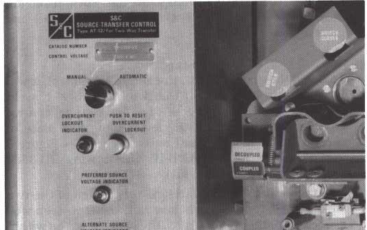
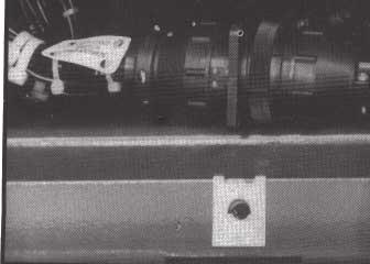
2 S8C Source-Transfer PMH Pad-Mounted Gear Outdoor Distribution (14.4 kv and 25 kv) I INTRODUCTION - Continued Replacing Type AT-12 Control With Micro-AT Control In Gear Having 734 Supplement to the Catalog Number Service Kit is included with Retrofit Kit Catalog Number %-inch ratchet-type socket wrench with 6-inch SDA This kit includes a wrist strap for connecting extension and open-end wrench for 5/16-18 hexthe person installing the Micro-AT Source-Transfer head cap screws. Control, along with a static-dissipative work mat, to 0 9/16-inch ratchet-tme socket wrench and open-end the same ground point. wrench for % - 16 hex-head cap screws. As 3 s instructions point out, the use of a static- 5/16.inch nut driver or wrench for #6 32 dissipative work surface is effective for removing static hex nuts. from conductive objects like the human body and metal llhz-inch nut driver or open-end wrench for parts. It is not effective on nonconductive objects such #8-32 hex nuts. as synthetic clothing, plastic coffee cups, cigarette packs, vinyl work order envelopes, or common Flat-blade screwdriver for #6-32 machine screws. plastics-which can carry large amounts of static Flat-blade screwdriver for #10 32 machine screws. charge. Care should thus be taken to keep such material &inch deep-well socket, to break off existing weld as far away from the work area as possible. studs. Tools Required WLong-nose pliers, to remove cotter pins if mechanical antiparalleling feature was furnished. %inch ratchet-type socket wrench and open-end wrench for #10-32 hex-head cap screws and hex Side cutters, to cut tie wraps. nuts. 0 Voltmeter impedance having input an of at least 5,000 7/16-inch ratchet-type socket wrench and open-end ohms per volt. wrench for /4-20 hex-head cap screws and hex Flashlight. nuts. I I REMOVING THE TYPE AT-I2 SOURCE-TRANSFER CONTROL I step 1 Open the doors to the low-voltage control compartment and secure them with the door holders. Step 2 The door for the left-hand side of the low-voltage control compartment is secured at the top and bottom by two % -16 X 1 truss-head zinc-plated machine screws. The screw at the bottom wil interfere with the Micro-AT Source-Transfer Control when it is installed, and must be replaced with a shorter screw. Remove and discard the bottom screw and install the % -16 X 3/4 trusshead zinc-plated machine screw (furnished in the retrofit kit). Step 3 Place the manual/automatic operation selector switch on the Type AT-12 Source-Transfer Control faceplate in the MANUAL position. See Figure 1. Step 4 Decouple each stored-energy operator by grasping the associated decoupler and turning it counterclockwise 5 to 6 complete turns, until firm resistance is felt and the DECOUPLED target is centered in the indicator port. See Figure 2. step 5 Remove the bolted cover labeled Source-Transfer Control Switches and Timers to gain access to the programming panel of the Type AT-12 Source-Transfer Control. See Figure 4. Discard this cover. (The retrofit kit includes a cover assembly for the Micro-AT Source- Transfer Control which wil cover this opening.) Step 6 Measure and record the difference in voltage-sensor signals between Phase 1 of the preferred source and Phase 1 of the alternate source, by inserting the voltmeter test probes into the appropriate test jacks on the programming panel. See Figure 4. Similarly, measure and record the difference in voltage-sensor signals between Phase 2 of the preferred source and Phase 2 of the alternate source. Then measure and record the difference in voltage-sensor signals between Phase 3 of the preferred source and Phase 3 of the alternate source. If any measurement exceeds 0.75 volts, the sequence of rotation of the two signal sources is different; refer to Drawing RD-3631 (furnished in the retrofit kit) and make the necessary voltage-sensor signal input change to Main Wiring Harness Part Number SDA-2333 (also furnished in the retrofit kit) INSTRUCTION SHEET Page 2 of 23 January 18,1993 COMPANY ELECTRIC S&C LTD. S&C CANADA ELECTRIC Chicago 0 Toronto


3


4


5
6 SIC Source-Transfer Replacing Type AT-12 Control PMH Pad-Mounted Gear With Micro-AT Control Outdoor Distribution (14.4 kv and 25 kv) In Gear Having R4 Supplement to the Catalog Number I REMOVING THE TYPE AT-12 SOURCE-TRANSFER CONTROL - Continued I Step 11 terminals port access of the switch. Retain the Remove the switch operator vertical access panels from hardware. Mark the positions of the leads and both the left-hand and right-hand sides of the low- disconnect them. voltage control compartment, using the following procedure. (a) Remove the bolted cover labeled Terminal Blocks on each side. See Figure 5. Failure to mark the original positions of the wire (b) The switch operator vertical access panel on each leads may result in improper reconnection that wil side is secured by five 1/4-20 X 3/4 hex-head render the pad-mounted gear inoperative. stainless-steel cap screws, lockwashers, and flat washers. See Figure 5. Two wire leads are connected (c) Remove the lower-center access panel surrounding to the charging-shaft access port switch on the back the Type AT-12 Source-Transfer Control faceplate, of each panel. Remove the five screws and which is secured at the bottom by a /4-20 X % associated lockwashers and flat washers from each hex-head stainless-steel cap screw, lockwasher, and switch operator vertical access panel, taking care flat washer. See Figure 5. Discard the access panel not to damage the wire leads or to bend the but retain the hardware INSTRUCTION SHEET Page 6 of 23 January 18,1993 S&C COMPANY ELECTRIC Chicago ELECTRIC S&C CANADA LTD. Toronto

7
8


9
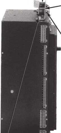
10 S8C Source-Transfer Replacing Type AT-12 Control PMH Pad-Mounted Gear With Micro-AT Control Outdoor Distribution (14.4 kv and 25 kv) In Gear Having R4 Supplement to the Catalog Number I REMOVING THE MECHANICAL ANTIPARALLELING FEATURE I If the pad-mounted gear is furnished with optional mechanical antiparalleling feature (Catalog Number Suffi -CY or -Cl7 ), this feature must be disconnected and permanently removed using the following procedure, in order to accommodate the Micro-AT Source-Transfer Control. Step 1 Remove and discard the 1/16 X % stainless-steel cotter pin which connects each link of the antiparalleling mechanism to its respective switch drive lever. See Figure 8. and lower mounting plates of the antiparalleling mechanism. See Figure 8. Discard the antiparalleling I mechanism. step 3 To avoid interference with the Micro-AT control, it wil be necessary to break off the two 5/16-18 X 1 weld studs on the back wall of the low-voltage control compartment, to which the lower mounting plate of the antiparalleling mechanism is attached. See Figure 8 and Sections A-A and B-B on Drawing RD-3582 (furnished in the retrofit kit). Attach a flat washer and hex nut to each of the two weld studs. Tighten each hex nut, using a deep-well step 2 Remove and discard the four 5/16-18 zinc-plated socket, the weld fa&... the break must be within serrated hex nuts which are used to attach the upper % inch ofthe back wall. 3 L L 1 i I INSTRUCTION SHEET Page 10 of 23 January 18,1993 ELECTRIC S&C ELECTRIC S&C COMPANY 0 Chicago CANADA LTD. 0 Toronto


11


12

13
14 SBC Source-Transfer Replacing Type AT-12 Control PMH Pad-Mounted Gear With Micro-AT Control, Outdoor Distribution (14.4 kv and 25 kv) In Gear Having R4 Supplement to the Catalog Number INSTALLING THE MICRO-AT SOURCE-TRANSFER CONTROL - Continued i Step 7 For pad-mounted gear models rated 14.4 lcv: To avoid interference during installation, it wil be necessary to temporarily remove the front panel assembly of the Micro-AT Source-Transfer Control. Since the control will then be susceptible to damage from static charges, a 3M 8501 Portable Static-Dissipative Field Service Kit has been included in Retrofit Kit Catalog Number SDA e static-dissipative kit must be utilized until the front panel assembly is reattached in Step 12, Set up the static-dissipative kit and remove the front panel assembly of the Micro-AT Source-Transfer Control using the following procedure. (a) Open up the static-dissipative work mat in front of the low-voltage control compartment. See Figure 13. (b) Place the Micro-AT Source-Transfer Control on the static-dissipative work mat. See Figure 13. (cj Attach the ground cord assembly onto the work mat by means of the large black snap. Attach the alligator clip on the shorter of the two wire leads to the aluminum clip on the gearbox mounting assembly, on the left-hand side of the low-voltage control compartment. See Figure 13. (dj Slip on the elastic wrist strap and attach the band so that it fits snugly, but comfortably. Attach the longer of the two wire leads on the ground cord assembly to the wrist band by means of the small plastic snap. See Figure 13. (e> Remove the four #8-32 hex nuts which secure the front panel assembly to the Micro-AT Source- Transfer Control enclosure. See Figure 13. Retain the hardware. Carefully disconnect the ribbon connector from the receptacle on the back of the front panel assembly. See Figure 16. Place the front panel assembly on the static-dissipative work mat INSTRUCTION SHEET 14 Page of 23 ELECTRIC S&C COMPANY Chicago January 18,1993 ELECTRIC S&C CANADA LTD. Toronto


15


16

17

18
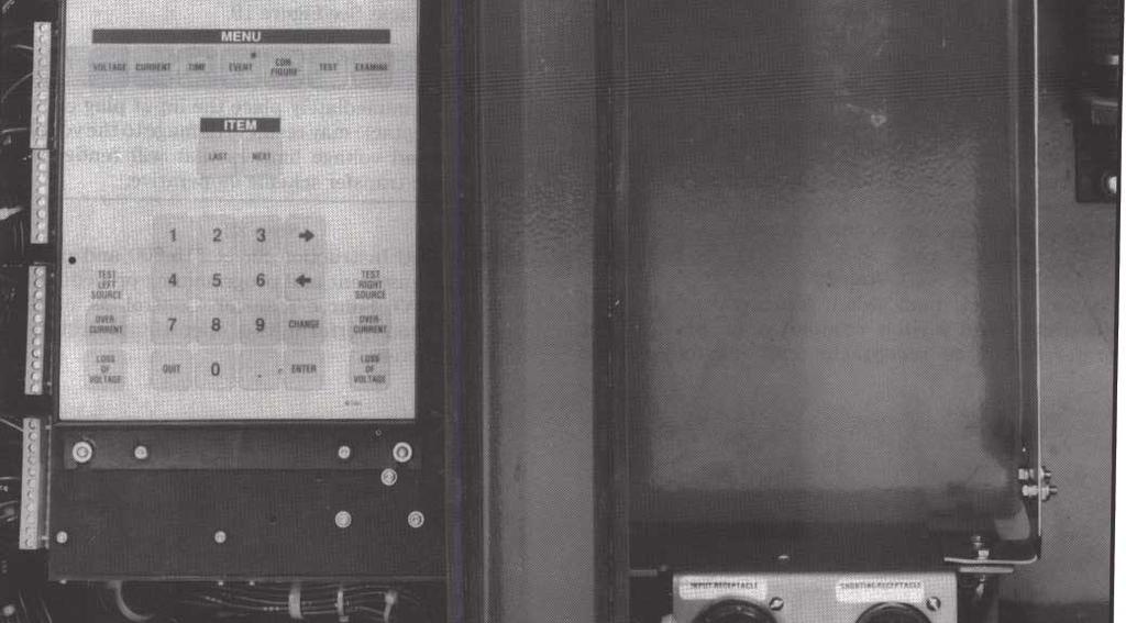
19 LlNSTALLlNG THE MICRO-AT SOURCE-TRANSFER CONTROL - Continued 1 self-locking hex nuts. See Figure 18 (top). Fingertighten the screws. Attach, to the bottom of the partition, L Bracket Part Number SD-2772 using two #10-32 X % hexhead stainless-steel cap screws, two flat washers, and self-locking hex nuts. See Figure 18 (bottom). Finger-tighten the screws. Attach the L, bracket to the lower mounting bracket assembly using two #10-32 X % hex-head stainless-steel cap screws, two flat washers, and self-locking hex nuts. See Figure 18 (bottom). Securely tighten all the screws. Step 18 Refer to Drawing RD-3617 Sheet 1 of 2 (furnished in the retrofit kit) and perform the rewiring procedure indicated for the existing wiring in the left-hand side of the low-voltage control compartment. Step 19 Refer to Drawing RD-3617 Sheet 2 of 2 (furnished in the retrofit kit) and perform the rewiring procedure indicated for the existing wiring in the right-hand side of the low-voltage control compartment. Step 20 Connect the left-hand switch compartment plug and the right-hand switch compartment plug to the preferred-source receptacle and alternate-source receptacle on Main Wiring Harness Part Number SDA-2333, based on the settings noted previously. See Figure 19. Fcn-pad-mountedgear models furnished with optional remote indication feature (Catalog Number SuJfd -Y4 1): Connect the remote indication plug to the receptacle on Remote Indication Wiring Harness Part Number SDA step 21 Temporarily reconnect the wire leads to the chargingshaft access port switches on the back of the switch operator vertical access panels for the left-hand and right-hand sides. See Figure 21. Loosely reattach the access panels. Then remove the input plug from the shorting receptacle and immediately transfer it to the input receptacle. See Figure 19. input receptacle may result in damage to the voltage sensors and voltage limiters that wil render the step 22 Refer to S&C Instruction Sheet and perform the field adjustment and programming procedures for the Micro-AT Source-Transfer Control as outlined therein. Then perform the operational testing as outlined therein. INSTRUCTION SHEET ELECTRIC S&C COMPANY Chicago Page 19 of 23 LTD. S&C CANADA ELECTRIC January Toronto 18,1993


20
21 I INSTALLING THE MICRO-AT SOURCE-TRANSFER CONTROL - Continued I Step 25 Replace the switch operator vertical access panels on the emergency-trip shaft, operator target, switchposition target, and decoupler indicator are the left-hand and right-hand sides of the low-voltage centered in their respective port openings. See control compartment, using the following procedure. Figure 5. (a) Reconnect the wire leads to the charging-shaft access port switch on the back of the switch Step 26 operator vertical access panel for the left-hand side. Replace the terminal-block access covers on the left- See Figure 21. Then reattach this access panel with hand and right-hand sides of the low-voltage control five '/4"-20 X 3/i" hex-head stainless-steel cap compartment. screws, lockwashers, and flat washers. Be sure that the emergency-trip shaft, operator target, switch- Step 27 position target, and decoupler indicator are Remove the input plug from the shorting receptacle centered in their respective port openings. See and immediately transfer it to the input receptacle. Figure 5. Also be sure to connect the chain for the See Figure 19. dual-purpose manual handle to the screw on the right-hand side of the access panel, near the center of the panel. See Figure 5. Failure to immediately place the input plug on the Reconnect the wire leads to the charging-shaft input receptacle may result in damage to the voltage access port switch on the back of the switch sensors and voltage limiters that wil render the operator vertical access panel for the right-hand automatic-transfer scheme inoperative. side. See Figure 21. Then reattach this access panel with five?4"-20 X %" hex-head stainless-steel cap screws, lockwashers, and flat washers. Be sure that INSTRUCTION SHEET S&C COMPANY ELECTRIC Page 0 Chicago 21 of 23 ELECTRIC S&C CANADA LTD. Toronto January 18,1993
22 SBC Source-Transfer Replacing Type AT-12 Control PMH Pad-Mounted Gear With Micro-AT'" Control Outdoor Disfribution (14.4 kv and 25 kv) In Gear Having "R4" Supplement to the Catalog Number I INSTALLING THE MICRO-AT SOURCE-TRANSFER CONTROL - Continued Step 28 Step 29 Attach the access cover assembly on the right-hand Attach the cover assembly for the Micro-AT Sourceside of the low-voltage control compartment, using the Transfer Control on the left-hand side of the low-voltage following procedure. control compartment, using the following procedure. (a) For models rated 14.4 kv: Attach Access Cover Assembly Part Number SDA-2384 (furnished in the retrofit kit). See Figure 20. Secure the access cover at the top with a knurled screw, retainer, neoprene washer, and nut. (b) For models rated 25 kv: Attach Access Cover Assembly Part Number SDA-2396 (furnished in the retrofit kit). See Figure 20. Secure the access cover at the top with a knurled screw, retainer, neoprene washer, and nut. (a) For models rated 14.4 kv: Attach Cover Assembly Part Number SDA-2387 (furnished in the retrofit kit). See Figure 20. Secure the cover assembly at the top with a knurled screw, retainer, neoprene washer, and nut. The front panel assembly of the Micro-AT Source-Transfer Control should be approximately centered in the opening of the cover assembly and the connectors of the Main Wiring Harness should not be exposed. If necessary, loosen the hardware which retains the Micro-AT Source- Transfer Control enclosure, reposition the enclosure, and then securely retighten the hardware. I 0 0 I n :lo O 0 " C 0. T oooo a 0 0 " 0 Io D- I o J t rer Assembl t Number SI Y [for pad-mounted gear rated 14.4 kv or Cover Assembly Part Number SDA-2398 :for' pad-mounted gear rated 25 kv) lr I Access Cover Assembly Part Number SDA (for pad-mounted gear rated 14.4 kv or Access Cover Assembly Part Number SDA (for pad-mounted gear rated 25 kv) 1 8 CI 0 663m5 12 INSTRUCTION SHEET ELECTRIC Page S&C 22 of 23 COMPANY Chicago January 18,1993 S&C ELECTRIC CANADA LTD. Toronto


23
INSTRUCTIONS. Section Page Number Section Page Number REMOVING THE MECHANICAL ANTIPARALLELING S&C ELECTRIC COMPANY 0 Chicago
 SBC Source-Transfer PMH Pad-Mounted Gear Outdoor Distribution (14.4 kv and 25 kv) Replacing Type AT-1 2 Control With Micro-AT Control n Gear Having Rl or R2 Supplement to the Catalog Number TABLE OF CONTENTS
INSTRUCTIONS For Field Replacement
 SBC Source-Transfer Outdoor Distribution (14.4 kv and 25 kv) Replacing Type AT-1 2 Control With Micro-ATTM Control n Gear Having R3 NSTRUCTONS For Field Replacement TABLE OF CONTENTS 1 Section Page Number
INSTRUCTIONS I INTRODUCTION I TABLE OF CONTENTS. %!kc TypeAT-2,TypeAT-3,orTypeAT-12Source- S8C Type AT Source-Transfer Controls I Field Replacement
 S8C Type AT Source-Transfer Controls Field Replacement NSTRUCTONS TABLE OF CONTENTS Section Page Number Section Page Number NTRODUCTON... 1 RE LACNG TYPE AT-2 SOURCE-TRANSFER CONTROL N REPLACNG TYPE AT-2
INSTRUCTIONS For Field Assembly and Installation
 S&C Line-Rupters" Outdoor Transmission (115 kv through 230 kv) I For Line and Cable Switching INSTRUCTIONS For Field Assembly and Installation ITABLE OF CONTENTS I Section Page Number Section Page Number
BEFORE BEGINNING INSTALLATION
 COMPLETE CHASSIS FUEL LINE KITS For 1996-2000 Honda Civic Equipped with B-Series Engine INSTALLATION INSTRUCTIONS PLEASE study these instructions carefully before beginning this installation. Most installations
2015 Mustang Lightbar (All Models) CDC#
 CDC#") 2015 Mustang Lightbar (All Models) CDC# 1511-7000-01 Components: 1 CDC Lightbar Note: READ instructions before starting installation!!! CDC Part# Driver side bracket 0511-6001-05 Passenger side bracket
2015 Mustang Lightbar (All Models) CDC# 1511-7000-01 Components: 1 CDC Lightbar Note: READ instructions before starting installation!!! CDC Part# Driver side bracket 0511-6001-05 Passenger side bracket
ELECRAFT KX3 Application Note
 ELECRAFT KX3 Application Note Installing the Speaker Grille Cloth Revision A, July 30, 2012 Copyright 2012, Elecraft, Inc., All Rights Reserved Background Some KX3 owners have reported issues with the
Introduction CAUTION. S&C Power Operated Metal-Enclosed Switchgear Outdoor Distribution (4.16 kv, through 34.5 kv)
") S&C Power Operated Metal-Enclosed Switchgear Outdoor Distribution (4.16 kv, through 34.5 kv) Inspection Recommendations for Switchgear with Type AT-3 Source- Transfer Controls Table of Contents Section
S&C Power Operated Metal-Enclosed Switchgear Outdoor Distribution (4.16 kv, through 34.5 kv) Inspection Recommendations for Switchgear with Type AT-3 Source- Transfer Controls Table of Contents Section
Installation And Operation
 S&C Series 2000 Circuit-Switchers Outdoor Transmission Model 2020 With Vertical Interrupters and Side-Break Power-Operated Disconnect 69 kv through 138 kv Installation And Operation Table of Contents Section
Introduction CAUTION CAUTION. S&C Power Operated Metal-Enclosed Switchgear Indoor and Outdoor Distribution (4.16 through 34.5 kv)
") S&C Power Operated Metal-Enclosed Switchgear Indoor and Outdoor Distribution (4.16 through 34.5 kv) Inspection Recommendations for Switchgear Equipped with Type AT-2 Source-Transfer Controls Table of Contents
S&C Power Operated Metal-Enclosed Switchgear Indoor and Outdoor Distribution (4.16 through 34.5 kv) Inspection Recommendations for Switchgear Equipped with Type AT-2 Source-Transfer Controls Table of Contents
350Z / G35 Brake Master Cylinder Brace
 Z1 Motorsports 2877 Carrollton - Villa Rica Hwy Carrollton GA 30116 770.838.7777 350Z / G35 Brake Master Cylinder Brace PROLOGUE: Study these instructions completely and thoroughly before proceeding to
INSTALLATION INSTRUCTIONS
 INSTALLATION INSTRUCTIONS Accessory Application Publications No. SYSTEM 2005 ACCORD All 27511 (DX, LX) 2-AND 4-DOOR Issue Date AUG 2004 PARTS LIST Security System Attachment (LX): P/N 08E55-SDA-100A Unit
INSTRUCTIONS. S&c Circuit-Switchers - Mark v Grounding Switches - 70,000 Amperes Momentary Outdoor Transmission I INTRODUCTION INSTRUCTION SHEET 7 1 1
 S&c Circuit-Switchers - Mark v Grounding Switches - 70,000 Amperes Momentary With 90-degree opening blades NSTRUCTONS - - - - - - - - - - - - - - For Field Assembly and nstallation NTRODUCTON CAUTON: The
Installation Instructions HURST COMPETITION AND BILLET/PLUS SHIFTER Mustang w/5-speed Manual Transmission (GT only)
") Installation Instructions HURST COMPETITION AND BILLET/PLUS SHIFTER 2005-2010 Mustang w/5-speed Manual Transmission (GT only) Catalog# 3915201 WORK SAFELY! For maximum safety, perform this installation
Installation Instructions HURST COMPETITION AND BILLET/PLUS SHIFTER 2005-2010 Mustang w/5-speed Manual Transmission (GT only) Catalog# 3915201 WORK SAFELY! For maximum safety, perform this installation
Cleaning Flooded Gear
 S&C Manual PMX Modular Metal-Enclosed Switchgear Outdoor Distribution (13.8 kv and 25 kv) Cleaning Flooded Gear Table of Contents Section Page Section Page Introduction.... 2 Safety Information Understanding
Installation Instructions Z-Gate Shifter
 Installation Instructions Z-Gate Shifter Part Number 80681 1998, 2001 by B&M Racing and Performance Products The B&M Z-Gate shifter can be used in vehicles equipped with most popular three speed automatic
SCION tc ILLUMINATED DOOR SILLS Preparation
 Preparation Part Number: PTS21-21070 Kit Contents Item # Quantity Reqd. Description 1 2 Hardware Kit w/ power harness 2 1 Front Left Illuminated Door Sill Protector 3 1 Front Right Illuminated Door Sill
INSTALL INSTRUCTIONS C-VS-1500-DUR-1 15 VEHICLE SPECIFIC CONSOLE for Dodge Durango with OEM Center Shifter
 INSTALL INSTRUCTIONS C-VS-1500-DUR-1 15 VEHICLE SPECIFIC CONSOLE for 2011-2013 Dodge Durango with OEM Center Shifter TOOLS NEEDED: Phillips Screw Driver Standard Socket set Metric Socket set 90 Phillips
INSTALLATION INSTRUCTIONS C-VS-2000-DUR-1 20 VEHICLE SPECIFIC CONSOLE for 2018 Dodge Durango with Standard Shifter
 INSTALLATION INSTRUCTIONS C-VS-2000-DUR-1 20 VEHICLE SPECIFIC CONSOLE for 2018 Dodge Durango with Standard Shifter TOOLS REQUIRED: Phillips Screw Driver T-20 Torx bit Standard Socket set 9/64 Allen wrench
Installation Instructions COMPETITION/PLUS SHIFTER Ford Mustang MT82 6-Speed Manual Transmission Catalog#
 Installation Instructions COMPETITION/PLUS SHIFTER 2015-2017 Ford Mustang MT82 6-Speed Manual Transmission Catalog# 3916037 Rev. 00 WORK SAFELY! For maximum safety, perform this installation on a clean,
Hurst VMATIC3 INSTALLATION
 FORM 159 8530 07/12 Hurst VMATIC3 3-Speed & 4-Speed Automatic Shifter Catalog #3838530 2012 by Hurst Performance The Hurst Vmatic3 shifter can be used in vehicles equipped with most popular three speed
Replacement of 600-Ampere Bushing and 200-Ampere Bushing-Well Adapters
 S&C Vista SD Underground Distribution Switchgear Pad-Mounted and Vault-Mounted Style Outdoor Distribution (17.5 kv and 29 kv) With Visi-Gap Load Interrupter Switches and Visi-Gap Fault Inetrrupters Replacement
Digitrip Retrofit System for ITE K-3000, K-3000 S, K-4000 and K-4000 S Breakers
 Supersedes IL 33-858-4 Dated 05/02 Digitrip Retrofit System for ITE K-3000, K-3000 S, K-4000 and K-4000 S Breakers Digitrip Retrofit System for ITE K-3000, Digitrip Retrofit System for ITE K-3000, K-3000
Cleaning Flooded Gear
 S&C Manual Metal-Enclosed Switchgear Indoor and Outdoor Distribution (4.16 kv through 34.5 kv) Cleaning Flooded Gear Table of Contents Section Page Section Page Introduction.... 2 Safety Information Understanding
Rollstar Shade Installation Instructions
 Rollstar Shade Installation Instructions All Lifting Systems Inside or Outside Mount Thank you for purchasing your new Rollstar shade. It has been custom-made from the highest quality materials to the
Technical Support (707)
") Installation Instructions CONSOLE MEGASHIFTER Fits: 1982-1992 Camaro & Firebird w/automatic Transmission *except 1988-1992 Firebird Formula Model Catalog # 80692 WORK SAFELY! For maximum safety, perform
Installation Instructions CONSOLE MEGASHIFTER Fits: 1982-1992 Camaro & Firebird w/automatic Transmission *except 1988-1992 Firebird Formula Model Catalog # 80692 WORK SAFELY! For maximum safety, perform
Installation Instructions. QuickSilver Shifter. Fits: GM, Ford, Chrysler Transmissions See Application Guide for Specific Applications Part # 80683
 Installation Instructions QuickSilver Shifter Fits: GM, Ford, Chrysler Transmissions See Application Guide for Specific Applications Part # 80683 WORK SAFELY! For maximum safety, perform this installation
TCI FastGate Shifter Installation Instructions
 151 INDUSTRIAL DRIVE ASHLAND, MISSISSIPPI 38603 http://www.tciauto.com TELEPHONE: 662-224-8972 FAX LINE: 662-224-8255 E-MAIL: tech@tciauto.com TCI 616541 FastGate Shifter Installation Instructions The
RANGER 900 POWER STEERING KIT
 RANGER 900 POWER STEERING KIT P/N 2880083 APPLICATION MY14 AND NEWER RANGER XP 900 MODELS IMPORTANT It is strongly recommended that this kit be installed by an authorized Polaris dealer. NOTE Use of this
INSTALLATION INSTRUCTIONS
 INSTALLATION INSTRUCTIONS Accessory Application Publications No. SYSTEM ACCORD 2-DOOR (LX/EX L4, LX V6) AII 25749 Issue Date FEB 2004 PARTS LIST Double-sided adhesive tape XM Radio Attachment Kit : P/N
S&C Vista Underground Distribution Switchgear
 S&C Vista Underground Distribution Switchgear Pad-Mounted, Vault-Mounted, and UnderCover Styles Instructions For Installation and Operation of Portable Motor Operator TABLE OF CONTENTS Section Page Section
Z-Gate Universal Shifter
 Installation Instructions Z-Gate Universal Shifter Fits: GM, Ford, Lincoln and Chrysler Transmissions See Application Guide for Specific Applications Part #80681 Rev 06/01/2018 WORK SAFELY! For maximum
PLEASE READ THIS INSTRUCTIONS CAREFULLY, BEFORE YOU START INSTALLATION
 INSTALLATION INSTRUCTIONS PART NUMBER: L0SXC000 DESCRIPTION: 09 ASCENT TRAILER HITCH PLEASE READ THIS INSTRUCTIONS CAREFULLY, BEFORE YOU START INSTALLATION SAFETY PRECAUTION: When installing Trailer Hitch,
Torqueflite Manual/Automatic Valve Body
 TCI 122400 Torqueflite Manual/Automatic Valve Body This valve body can be installed in a few hours by carefully following directions. Read all instructions first to familiarize yourself with the parts
MINI COOPER HAVING INSTALLATION QUESTIONS? CALL TECHNICAL SUPPORT AT DESIGNED FOR USE WITH BALL MOUNT # D-19 / 45519
 10/8/2012 PAGE 1 of 6 ITEM 1 QTY 8 Parts List PART NUMBER DESCRIPTION 3/8" CONICAL TOOTHED WASHER TOOLS REQUIRED RATCHET TORQUE WRENCH 12" EXTENSION 12mm SOCKET 8mm SOCKET OFFSET SCREWDRIVER FLAT BLADE
Mishimoto Performance Aluminum Mustang Radiator - Manual - (94-95 GT/Cobra/V6) - Installation Instructions
 - Installation Instructions") Mishimoto Performance Aluminum Mustang Radiator - Manual - (94-95 GT/Cobra/V6) - Installation Instructions The below installation instructions work for the following products: Mishimoto Performance Aluminum
Mishimoto Performance Aluminum Mustang Radiator - Manual - (94-95 GT/Cobra/V6) - Installation Instructions The below installation instructions work for the following products: Mishimoto Performance Aluminum
Installation Instructions Right Hand Drive Megashifter
 Installation Instructions Right Hand Drive Megashifter Part Number 80685 1995, 2001, 2006, 2010 by B&M Racing & Performance Products The B&M Right Hand Drive Megashifter is designed specifically for vehicles
INSTRUCTIONS. 1 Schematic. I Device ' I. S8C Switch Operators - Type CS-24. For Operation
 Number 38840R1-B. The NSTRUCTON S8C Switch Operators - Type CS-24 NSTRUCTONS For Operation CAUTON: The equipment covered by this publication must be operated and maintained by qualified persons who are
INSTALLATION INSTRUCTIONS
 INSTALLATION INSTRUCTIONS Accessory Application Publications No. SECURITY SYSTEM P/N 08E49-SDA-100 ACCORD 2- AND 4-DOOR AII 30666 Issue Date AUG 2005 PARTS LIST Hood switch harness Illustration of the
Installation Instructions Megashifter
 Installation Instructions Megashifter The B&M Megashifter shifter can be used in vehicles equipped with most popular three speed or four speed automatic transmissions. Your B&M Megashifter comes equipped
Light Truck MegaShifter
 Installation Instructions Light Truck MegaShifter The B&M Light Truck Megashifter shifter is designed to be used in most light trucks equipped with most popular three speed or four speed automatic transmissions.
HURST COMP/PLUS SHIFTER 2015 Ford Mustang (Getrag MT82 six-speed manual transmission) Catalog # by Hurst Performance
 Catalog # by Hurst Performance") FORM 159 0205 07/15 HURST COMP/PLUS SHIFTER 2015 Ford Mustang (Getrag MT82 six-speed manual transmission) Catalog #391 0205 2015 by Hurst Performance Thank you for purchasing the Hurst Comp/Plus Shifter.
FORM 159 0205 07/15 HURST COMP/PLUS SHIFTER 2015 Ford Mustang (Getrag MT82 six-speed manual transmission) Catalog #391 0205 2015 by Hurst Performance Thank you for purchasing the Hurst Comp/Plus Shifter.
PACER 30 VACUUM IMPORTANT SAFETY INSTRUCTIONS READ AND UNDERSTAND ALL INSTRUCTIONS BEFORE OPERATING OR SERVICING MACHINE
 DANGER! PACER 30 VACUUM IMPORTANT SAFETY INSTRUCTIONS READ AND UNDERSTAND ALL INSTRUCTIONS BEFORE OPERATING OR SERVICING MACHINE Failure to Observe These Instructions Can Cause Fire, Electrical Burn, Shock
Installation Instructions QUICKSILVER CONSOLE SHIFTER Fits: Chevelle / El Camino
 WORK SAFELY! For maximum safety, perform this installation on a clean, level surface and with the engine turned off. Place blocks or wedges in front of and behind both rear wheels to prevent movement in
Instructions for Installation and Operation
 S&C Alduti-Rupter Switches Outdoor Distribution Three-Pole Vertical-Break Style Reciprocating Operating Mechanism 25/34.5 kv and 34.5 kv Instructions for Installation and Operation TABLE OF CONTENTS Section
Installation and Operation
 S&C Series 2000 Circuit-Switchers Outdoor Transmission Model 2030 With Vertical Interrupters and Without Disconnect 69 kv through 230 kv Installation and Operation Table of Contents Section Page Section
THIS PRODUCT IS FOR PROFESSIONAL LABORATORY USE ONLY USER'S MANUAL. WELLS ENGINE UNIT 230 VOLT Product No. U905, U906, U907, U908
 DENTAL, INC. TECHNICAL BULLETIN U807-022510 5860 FLYNN CREEK ROAD READ ALL INSTRUCTIONS P.O. BOX 106 BEFORE PROCEEDING COMPTCHE, CALIFORNIA, U.S.A. 95427 SAVE THIS FOR FUTURE REFERENCE THIS PRODUCT IS
Installation Instructions HURST BILLET COMPETITION/PLUS SHIFTER Dodge Challenger
 Installation Instructions HURST BILLET COMPETITION/PLUS SHIFTER 2009-2015 Dodge Challenger Catalog #3916020 WORK SAFELY! For maximum safety, perform this installation on a clean, level surface and with
Service Manual. LT-5 Lawn Tractor
 Service Manual LT-5 Lawn Tractor NOTE: These materials are for use by trained technicians who are experienced in the service and repair of outdoor power equipment of the kind described in this publication,
EnDuraLast II Charging System Installation Guidlines
 EnDuraLast II Charging System Installation Guidlines Notes & Disclaimers: The installation of this charging system assumes the installing technician has basic mechanical and electrical skills. Please understand
N/S= Not Shown Bold = Part available for purchase. Italic = Part not available for purchase, listed and shown for reference only.
 Media Rewind Upgrade Installation Instructions Prepare for Installation This kit includes the parts and documentation necessary to install the media rewind option kit into the 105SL printers. Read these
ProTrip Conversion Kits. For GE Types AK-15, AK-25, and AKU- 25 Low-Voltage Power Circuit Breakers INTRODUCTION. DEH Installation Instructions
 DEH 40026 Installation Instructions g ProTrip Conversion Kits For GE Types AK-15, AK-25, and AKU- 25 Low-Voltage Power Circuit Breakers INTRODUCTION GE Conversion Kits are designed for upgrading existing
COYOTE CLOSURE ADOBE SERIES FOR UNDERGROUND, AERIAL, AND BURIED SPLICES 6.0" x 22" 8.5" x 22" (152.4 mm x mm mm x 558.
 FEBRUARY 2000 COYOTE CLOSURE ADOBE SERIES FOR UNDERGROUND, AERIAL, AND BURIED SPLICES 6.0" x 22" 8.5" x 22" (152.4 mm x 558.8 mm 215.9 mm x 558.8 mm) Be sure to read and completely understand this procedure
Installation Instructions for the EVO3 Height-Adjustable Ultimate Short Shifter
 Installation Instructions for the EVO3 Height-Adjustable Ultimate Short Shifter for 1992-2005 325, 323, 318 and 1986-1994 525, 528, 535, 540 5-speed models only. (part number USSE3 and USSE5) Thank you
Conflicts: Vehicles without a sunroof Vehicles with a single sunroof
 Toyota Sienna (Dual Sunroof) 2011-10.2 Overhead Video Part Number: 00016-00110 00016-00110-17 Fit Kit 00016-00120 00016-00120-17 Fit Kit Accessory Code: ED5 Conflicts: Vehicles without a sunroof Vehicles
RHINO SUSPENSION SYSTEM INSTALLATION INSTRUCTIONS
 PARTS INCLUDED: 2 FRONT UPPER A-ARMS 2 FRONT LOWER A-ARMS 2 UNI-BALL JOINTS 2 UNI-BALL JOINT STUDS 2 UNI-BALL JOINT CAPS 2 RETAINING RINGS 1 FRONT SHOCK ASSEM. 2 DELRON STEERING STOPS 2 SHOCK MOUNT SPACERS
Installation Instructions Console Megashifter
 Installation Instructions Console Megashifter 1968-1969 Camaro Part Number 81035 This B&M Megashifter is designed to fit in the console of a 1968-1969 Chevrolet Camaro. In 1968, these vehicles were equipped
TOYOTA 4-RUNNER TOWING HITCH Preparation
 Preparation Part Number: PT228-89460 Kit Contents 1 1 High Assembly 2 1 Wiring Harness Bracket 3 1 Hardware Bag 4 1 Hitch Cover 5 2 Frame Spacer 6 2 Center Spacer 7 1 Close-out Panel Hardware Bag Contents
Instructions for Installation
 S&C Circuit-Switchers Mark VI Outdoor Transmission 69 kv through 138 kv Option U, User-Furnished Mounting Structure Instructions for Installation TABLE OF CONTENTS Section Page Section Page INTRODUCTION
HIGH FLOW COLD AIR INTAKE SYSTEM INSTALLATION INSTRUCTIONS D , D A
 HIGH FLOW COLD AIR INTAKE SYSTEM INSTALLATION INSTRUCTIONS D760-0320, D760-0320A 1992-95 325i, is 1995 M3 (3.0L) Parts List: 1 Intake Tube 1 Silicone Hose 1 Air Flow Meter Bracket 1 Hose Clamp (#36z) 1
Desktop 5.5 Z Axis Retrofit
 Page 1 Kit parts Desktop 5.5 Z Axis Retrofit Carriage plate with stop bolt and Z proximity switch installed Zip ties Spare bolts Spindle mounting plate with stop bolt, spring mount, and rail Z proximity
Installation Instructions 1812 Folder Disk Clutch Retrofit Kit Martin Yale #WRA
 Installation Instructions 1812 Folder Disk Clutch Retrofit Kit Martin Yale #WRA1812510 Background: Early production Martin Yale Model 1812 Folders were originally equipped with a spring-clutch type feed
Installation and Operation
 S&C Three-Shot Type XS Fuse Cutout Outdoor Distribution (4.16 kv through 15 kv) Installation and Operation Table of Contents Section Page Section Page Introduction Qualified Persons... 2 Read this Instruction
PRO RATCHET UNIVERSAL SHIFTER
 Installation Instructions PRO RATCHET UNIVERSAL SHIFTER Fits: GM, Ford and Chryslers w/automatic Transmission See Application Guide for Specific Vehicles Catalog # 80842 WORK SAFELY! For maximum safety,
Better Bagger TM. Service Manual. 10-March
 Better Bagger TM 900e Service Manual 10-March-2005 www.betterpackages.com CONTENTS Parts list with reorder numbers. Page 1 Parts Identification Photographs Pages 2-4 Service Instruction Pages 5-10 The
INSTALLATION INSTRUCTION 88146
 INSTALLATION INSTRUCTION 88146 Rev H FOR RANCHO SUSPENSION SYSTEM RS6547: 4WD SUBURBAN/YUKON XL, 4WD TAHOE/YUKON, & 4WD AVALANCHE READ ALL INSTRUCTIONS THOROUGHLY FROM START TO FINISH BEFORE BEGINNING
WINCH MOUNT KIT FOR POLARIS RANGER P/N ASSEMBLY / OWNERS MANUAL. Application WINCH KIT NO. 25-9xxx
 WINCH MOUNT KIT FOR POLARIS RANGER P/N 25-3300 ASSEMBLY / OWNERS MANUAL Application WINCH KIT NO. 25-9xxx Before you begin, please read these instructions and check to be sure all parts and tools are accounted
Installation Instructions
 Important Parts Installation Instructions INSTALLATION REQUIRES WELDING by a qualified welder or metal fabricator. Weld-on installation is strongly recommended for maximum strength and reinforcement of
DYNA OIL COOLER AND THERMOSTAT KIT
 INSTRUCTIONS -J000 REV. 07-5-00 Kit Numbers 6985-0 (Chrome) and 6989-0 (Silver) General DYNA OIL COOLER AND THERMOSTAT KIT These oil cooler kits feature a thermostat built-in to the oil filter mount. These
HAVING INSTALLATION QUESTIONS? CALL TECHNICAL SUPPORT AT DESIGNED FOR USE WITH BALL MOUNT # 36053B
 2/20/2013 ITEM 1 QTY 8 Parts List PART NUMBER DESCRIPTION 3/8" CONICAL TOOTHED WASHER TOOLS REQUIRED RATCHET TORQUE WRENCH 12" EXTENSION 12mm SOCKET 8mm SOCKET OFFSET SCREWDRIVER FLAT BLADE SCREWDRIVER
Service Jacks. Operating Instructions & Parts Manual. Model Number. Capacity 4 Ton 4 Ton Air/ Manual 10 Ton 10 Ton Air/ Manual HW93657/ HW93660
 Service Jacks Operating Instructions & Parts Manual Model Number HW93657 HW93667 HW93660 HW93662 Capacity 4 Ton 4 Ton Air/ Manual 10 Ton 10 Ton Air/ Manual Made in North America HW93657/ HW93660 HW93667/
M14 AUTOMOTIVE SPARK PLUGS AND WIRES CONVERSION KIT INSTALLATION INSTRUCTIONS
 M14 AUTOMOTIVE SPARK PLUGS AND WIRES CONVERSION KIT INSTALLATION INSTRUCTIONS (It is highly recommended you read the instructions completely before beginning) 1. Be sure the magneto switches are turned
S Voltage Regulators PRODUCT INFORMATION GENERAL. Contents. Acceptance and Initial Inspection. Handling and Storage.
 Voltage Regulators QD3/T350 Main Movable Contact Assembly Kit Kit 5741325B04 Service Information S225-50-42 Contents General..................................... 1 Tools Required..............................
Installation Instructions StarShifter
 Installation Instructions StarShifter Part Number 80675 2000 by B&M Racing & Performance Products LLC The B&M StarShifter can be used in vehicles equipped with most popular three speed automatic transmissions.
Eibach Pro-Damper Shocks & Struts (05-09 All):
:") Eibach Pro-Damper Shocks & Struts (05-09 All): Required tools: 3/8 and 1/2 drive ratchets 7, 8, 10, 15, 16, 17, 18, 21 & 22 mm open ended wrenches 8 & 10 mm box end wrenches 10mm socket 13, 15 & 18 mm
Eibach Pro-Damper Shocks & Struts (05-09 All): Required tools: 3/8 and 1/2 drive ratchets 7, 8, 10, 15, 16, 17, 18, 21 & 22 mm open ended wrenches 8 & 10 mm box end wrenches 10mm socket 13, 15 & 18 mm
S&C Circuit-Switchers Mark VI Installed on S&C Mounting Pedestals 84- through 102-inch Phase Spacing Outdoor Transmission (69 kv through 138 kv)
") S&C Circuit-Switchers Mark VI Installed on S&C Mounting Pedestals 84- through 102-inch Phase Spacing Outdoor Transmission (69 kv through 138 kv) Installation Table of Contents Section Page Section Page
S&C Circuit-Switchers Mark VI Installed on S&C Mounting Pedestals 84- through 102-inch Phase Spacing Outdoor Transmission (69 kv through 138 kv) Installation Table of Contents Section Page Section Page
BLACKBIRD INSTALLATION SUPPLEMENT
 BLACKBIRD INSTALLATION SUPPLEMENT 2008 GM 2500 AND 3500 6.6 DURAMAX DIESEL VERSION 5-08 Parts Included in Installation Kit Before beginning installation, check the parts kit thoroughly against the parts
Tools, Equipment and Supplies Needed:
 153-162 DISC BRAKE/DUAL MASTER CYLINDER CONVERSION Please take the time to read the enclosed instructions carefully. If you have any questions, call our Product Assistance personnel for clarifi cation.
Instruction Bulletin. Jockey Pump Controller
 Instruction Bulletin Jockey Pump Controller Installation Start Up Service This instruction bulletin is a guide for personnel involved with maintenance, engineering and approval of Fire Pump equipment and
INSTALLATION INSTRUCTIONS
 INSTALLATION INSTRUCTIONS Accessory Application Publications No. AII 32664 TRUNK MOUNT 2007 ACCORD 4-DOOR Issue Date JULY 2006 PARTS LIST 17 Wire ties Attachment Kit (sold separately): P/N 08B26-SDA-100
INSTRUCTIONS Ç CAUTION. S&C Power Fuses Types SMD-1A, SMD-2B, SMD-2C, and SMD-3. For Field Assembly and Installation NOTE INSTRUCTION SHEET
 S&C Power Fuses Types SMD-1A, SMD-2B, SMD-2C, and SMD-3 Outdoor Transmission Mountings Rated 34.5, 46, and 69 kv INSTRUCTIONS For Field Assembly and Installation TABLE OF CONTENTS Section Page Number INTRODUCTION........................................1
PARTS LIST CHARGER 2716 DB PLUS
 PARTS LIST CHARGER 2716 DB PLUS BASE ITEM PART NO. DESCRIPTION QTY. 101 6495511 CONTROL FRAME WELDMENT 1 102 9121390 11/32 I.D. X 11/16 O.D. X.051/.080 THICK SAE FLAT WASHER (5/16) 2 103 9121450 5/16-18
Installation Instructions. PowerFlex 700 Drive - Frame 8 Components Replacement
 Installation Instructions PowerFlex 700 Drive - Frame 8 Components Replacement Important User Information Solid-state equipment has operational characteristics differing from those of electromechanical
ROUSH Active IO Exhaust. Installation Instructions P/N: (R LITE) Fastback GT Convertible GT V8
 Fastback GT Convertible GT V8") Installation Instructions P/N: 422128 (R1318-5231LITE) Fastback GT Convertible GT V8 39555 Schoolcraft Rd, Plymouth MI, 48170 800.59.ROUSH ROUSH Active IO Exhaust Installation Instructions P/N: 422128
Installation Instructions P/N: 422128 (R1318-5231LITE) Fastback GT Convertible GT V8 39555 Schoolcraft Rd, Plymouth MI, 48170 800.59.ROUSH ROUSH Active IO Exhaust Installation Instructions P/N: 422128
CAUTIONS AND WARNINGS
 FIREWALL FORWARD FUEL LINE KITS For 1996-2000 Honda Civic Equipped with B-Series Engine INSTALLATION INSTRUCTIONS PLEASE study these instructions carefully before beginning this installation. Most installations
TOYOTA AVALON EC REARVIEW MIRROR
 Section I - Installation Preparation Part Number: PT732-07000 Section I - Installation Preparation Kit Contents Item # Quantity Reqd. Description 1 1 Full Mirror Assembly, Compass 2 1 Hardware Bag 3 1
INSTALLATION & OWNER S MANUAL
 INSTALLATION & OWNER S MANUAL CAB INSTALLATION INSTRUCTIONS FOR MASSEY FERGUSON 233, 428v (gear), 428v (hydro) SOFT SIDED CAB ENCLOSURE (p/n: MF233SS) This Curtis Cab is designed and manufactured for use
INSTALLATION INSTRUCTIONS
 Product: Steering Stabilizer Relocation Kit Part Number: JKSOGS900 (JKSOGS162/JKSJSPEC1000/JKSOGS924) INSTALLATION INSTRUCTIONS Applications: Wrangler JK, 2007+ Welcome CONGRATULATIONS on purchasing a
APPROXIMATE ASSEMBLY TIME (R&R): 45 minutes -1-
: 45 minutes -1-") PLOW ANGLE CONTROL KIT P/N 2879224 Application For use with the Glacier Pro Plow System P/N 2879103 on the below listed models MY09 and newer full size Ranger 500, 700 & 800 models MY13 and newer Ranger
PLOW ANGLE CONTROL KIT P/N 2879224 Application For use with the Glacier Pro Plow System P/N 2879103 on the below listed models MY09 and newer full size Ranger 500, 700 & 800 models MY13 and newer Ranger
RT1 SLIP-ON EXHAUST HONDA CBR600RR REV. A
 08-50-43733 REV. A PARTS INCLUDED Ref. Part Number Description Qty 1) 00-200-00064 Slip-on S-bend Assembly 1 2) 00-200-00088 RT1 Aluminum Muffler Assembly 1 3) 03-46-43058 Muffler Mounting Strap 1 4) 07-27-42566
SCION xa AUTO-DIMMING MIRROR Preparation
 Preparation Part Number: PT374-52040 (Compass) PT374-21050 (Homelink) Kit Contents Item # Quantity Reqd. Description 1a 1 AD Mirror Assembly w/compass & Map Lights (P/N PT374-52040) 1b 1 AD Mirror Assembly
INSTRUCTIONS For Field Assembly and Installation
 nteger Style NSTRUCTONS For Field Assembly and nstallation [TABLE OF CONTENTS Section Page Number Section Page Number NTRODUCTON... 1 NSTALLATON... 7 BEFORE STARTNG NSTALLATON....5 FNA1,CHECKS... 10 1
SPORTSTER SADDLEBAG KIT. i i02212
 General These saddlebags are designed to fit 99 and later Sportster Model Motorcycles, except XL00 Sport models with gas reservoir shock absorbers and 88R models. See the Service Parts pages for a list
Installation Instructions for the EVO3 Height-Adjustable Ultimate Short Shifter. for F80 M3 and F82 M4
 Installation Instructions for the EVO3 Height-Adjustable Ultimate Short Shifter for 2013+ F80 M3 and F82 M4 part number USSF80 Thank you for purchasing the Ultimate Shift Kit. Please read these directions
TOYOTA RAV TRAILER WIRE HARNESS Section I Installation Preparation
 Section I Installation Preparation Part Number: 08921-42900 Kit Contents Item # Quantity Reqd. Description 1 1 Converter 2 1 Wire harness 3 1 Sub wire harness No.1 4 2 Plastic Tie (300mm) 5 21 Plastic
TOYOTA YARIS HATCHBACK INTERIOR LIGHT UPGRADE Preparation
 Preparation Part Number PTS21-52062-08 NOTE: Part number of this accessory may not be the same as the part number show Kit Contents Item # Quantity Reqd. Description 1 1 12 Light Guide 2 1 7 Light Guide
GENUINE PARTS INSTALLATION INSTRUCTIONS
 GENUINE PARTS INSTALLATION INSTRUCTIONS DESCRIPTION: APPLICATION: PART NUMBER: Electronic Tailgate Lock Kit Nissan Titan 999M2-W3005 KIT CONTENTS: Item Qty. Part Description Service Part Number A 1 Electronic
Stealth Pro Ratchet Shifter
 Installation Instructions Stealth Pro Ratchet Shifter Part Number 81120 & 81121 (see www.bmracing.com for the latest technical product information) 2010, 2006 by B&M Racing and Performance Products The
TOYOTA VENZA 2009 TRAILER WIRE HARNESS Procedure
 Part Number: PT791-0T099 Kit Contents Item # Quantity Reqd. Description 1 1 Trailer Wire Harness Module 2 1 4-Flat Harness 3 1 Battery Power Wire Harness 4 1 Mounting Bracket, 4-Flat 5 2 Screw #10-24 6
INSTALLATION INSTRUCTIONS
 TABLE OF CONTENTS GENERAL...2 SPECIFICATIONS...2 PACKAGE CONTENTS...2 PACKAGE CONTENTS: ACCESSORIES...3 REQUIRED TOOLS...3 ADD-ON COMPONENTS...3 CLOSURE MOUNTING...3 LOCK AND UNLOCK EXTERIOR DOOR...3 CABLE