INSTRUCTIONS For Field Assembly and Installation
|
|
|
- Cecilia Potter
- 5 years ago
- Views:
Transcription

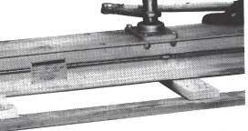
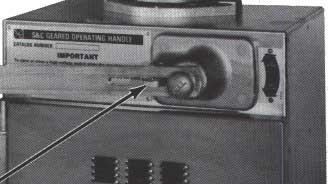
1 S&C Line-Rupters" Outdoor Transmission (115 kv through 230 kv) I For Line and Cable Switching INSTRUCTIONS For Field Assembly and Installation ITABLE OF CONTENTS I Section Page Number Section Page Number INTRODUCTION... 1 INSTALLING THE INTERPHASE SHAFT BEFORE STARTING INSTALLATION....3 INSTALLING THE OPERATOR....,15 ASSEMBLY OF INDIVIDUAL POLE-UNITS FINAL CHECKS AND ADJUSTMENTS I INTRODUCTION 1 The equipment covered by this publication must be selected for a specific application and it mustbe installed, operated, and maintained by qualified persons who are thoroughly trained and who understand any hazards that may be involved. This publication is written only for such qualified persons and is not intended to be a substitute for adequate training and experience in safety procedures for this type of equipment. General The following instructions are for field assembly (erection) and installation of S&C Line-Rupters. See Figure 1. The S&C Line-Rupter employs an in-series circuitbreaking interrupter and a circuit-making and isolating disconnect, making it especiallysuited for line and cable switching; specifically, load splitting (parallel or loop switching), load dropping, and line and cable dropping. Line-Rupter is capable of closing, carrying, and interrupting load currents and parallel loop or currents, as well as line- and cable-charging current. Line-Rupters utilize the time-proven reliability of the S&C Circuit-Switcher's brain and in-series interrupter, combined in a compact, economical, minimummaintenance switching package. Line-Rupter interrupters are economically tailored for specific applications by employing the precise number of interrupting gaps required. Each pole-unit of the S&C Line-Rupter includes a brain which provides built-in positive sequence control... and a fully enclosed stored-energy source dedicated solely to operation of the interrupter which is in the circuit at all times. Close-and-trip mechanisms are fully enclosed and protected, too. There are no external linkages, lever arms, cams, shunts, etc. that must be coordinated with a disconnect blade to accomplish circuit interruption. Positively sequenced operation is assured regardless of severe weather conditions such as high winds, rain, sleet, or snow. Line-Rupters can be manually operated by means of an S&C Manual Geared Operating Handle. Alternately, for remote supervisory control, power operation can be provided with an S&C Switch Operator-Type LS-2. For manually operated Line-Rupters, the degree of simultaneity of opening and closing of the three poleunits depends on the proper installation and adjustment of the operating mechanism-as well as on the speed of cranking at the operating handle-and must be considered in establishing ground-relay settings. Mounting of Line-Rupters S&C Line-Rupters are intended for upright mounting on S&C Mounting Pedestals or, alternately, for upright mounting on the user's steel pedestals or supporting structures which must meet specific static deflection limits shown in an S&C data sheet. The weight of the bus plus any associated ice load exerts a vertical force on upright-mounted Line-Rupter terminal pads. This vertical force must not exceed 400 pounds on either terminal pad. Seismic Withstand Capability S&C Line-Rupters, when installed with the recommended S&C Mounting Pedestals and anchor bolts, are capable of withstanding seismic loading of 0.2 ground Supersedes lnstructlon Sheet dated '1991 INSTRUCTION SHEET S&C COMPANY ELECTRIC Page 4 Chicago 1 of 17 S&C ELECTRIC CANADA LTD. Toronto December 16,1991


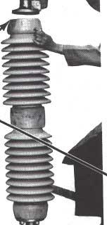
2 S&C Line-Rupters Outdoor Transmission (115 kv through 230 kv) INTRODUCTION - Continued I For Line and Cable Switching I acceleration in any direction, as well as performing as intended during such loading and afterward. Higher seismic withstand capabilities can be furnished on special application. Inspection Schedule and Procedures To assure Line-Rupter s continued proper performance, it should be inspected in accordance with S&C s recommended schedule and procedures contained in S&C Instruction Sheet Since the Type LS-2 Switch Operator is provided with a convenient means for decoupling it from the Line- Rupter, elective exercising of the operator may be performed at any time without requiring an outage or switching to an alternate source. 3 4-r I. ---I--I d-n* ~:-III~IIS: mnnuallv aaerated. and mounted on S&C Figure 1. S&C Line-Rupter ratea I 13 KV nommal, IL alllperv:rr GVIIIIIIL---, r-.----, Mounting Pedestals ~s~~ucm0N SHEET Page 2 of 17 December 16,199l S&C ELECTRIC COMPANY Chicago S&C ELECTRIC CANADA LTD. Toronto

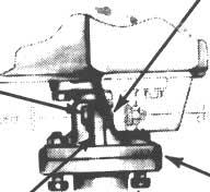
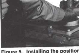
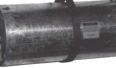
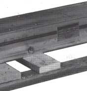
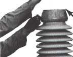
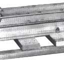
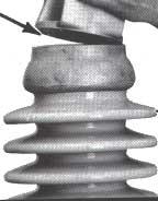
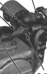
3 IBEFORE STARTING INSTALLATION 1 Checking the Shipment An S&C erection drawing will be found in a waterresistant envelope attached to the interrupter container on one of the three Line-Rupter pole-units. Study the erection drawing carefully and check the bill of material to be sure all parts are at hand. The Line-Rupter shipment should include the following items, as shown in Figure 2: 1. Three pole-units, each mounted on a skid, with the live parts attached directly to the insulatormounting flanges; Insulators, shipped in separate crates; Miscellaneous operating-mechanism components including a temporary adapter for hand operation of the individual pole-units; Interphase and vertical operating pipe; An S&C Manual Geared Operating Handle (if specified) or an S&C Switch 0perator"Type LS-2 (if specified, in place of a manual geared operating handle); S&C Mounting Pedestals (if Interrupter Target Line-Rupters are usually shipped with the interrupters in the open position. Therefore, the interrupter target, located on the side of each brain housing (see Figure S), will appear yellow. During the step-by-step instructions which follow, the disconnect blades will be moved to the fully open position. This will close the interrupter and charge and latch the stored-energy source within the brain, and the target will appear gray (normal). Whenin service, Line-Rupter interrupters should never be open when the blades are in the closed position. To close the interrupters, Line-Rupter must be completely opened and then reclosed. Gas-Pressure Indicator Line-Rupters have sealed interrupters containing gas under pressure. Loss of gas pressure may result in improper interrupting action. Low gas pressure is signaled by a red target in the gas-pressurc indicator at the terminal end of each interrupter. See Figure 2. A gray target indicates normal pressure. DO NOT INTERMIX COMPONENTS FROM DIFFERENT INSTALLATIONS S&C maintains an historical record-by serial number-of every Line-Rupter produced. This record lists information pertinent to each installation, such as application, date of shipment, and any service performed by S&C factory service specialists. This record is invaluable when questions arise relative to modifkations or replacements. It is important, therefore, that the various components belonging to a specific Line-Rupter installation not be intermixed with components belonging to a different installation. For this reason, each Line-Rupter is serially numbered. This serial number is stamped on the nameplate affixed to each individual pole-unit base and also on the nameplate affixed to the manual geared operating handle (or to the switch operator if the Line-Rupter is power operated). To facilitate identification during erection, the serial number, the sales-order number, and the erection-drawing (ED) number are marked on the top face of each Line-Rupter pole-unit base; on each pole-unit shipping crate or skid; and on all crates, boxes, and bundles for the other components associated with the installation. Please complete and mail the Line-Rupter registration card (enclosed in the water-resistant envelope) after the Line-Rupter has been installed. The information requested on this card is vital to ensure prompt notification in the event field modifications are needed. INSTRUCTION SHEET 752m500 S&C ELECTRIC COMPANY Chicago Page 3 of 17 S&C ELECTRIC CANADA LTD. Toronto December 16,1991


4
5


6


7


8


9


10


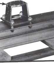
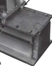
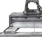
11
12
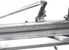
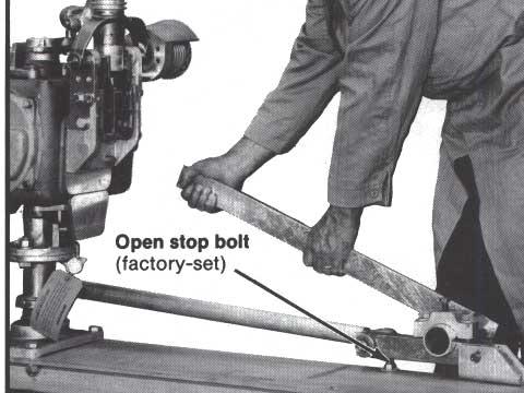
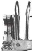
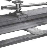
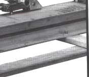
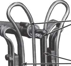
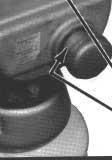
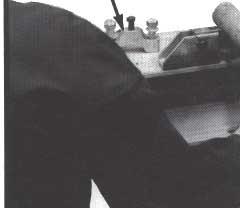
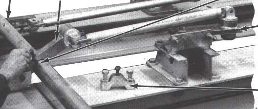
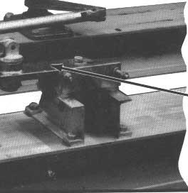
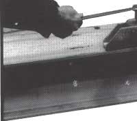
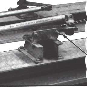
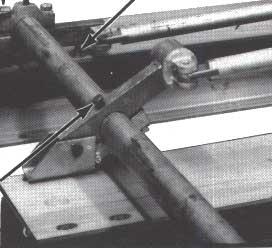
13 I INSTALLING THE INTERPHASE SHAFT step 22 Note: The base-mounted open stop bolt for each poleunit drive lever is factory-adjusted to achieve the travel (and positive-toggle condition) necessary to ensure positive latching of the stored-energy source within the brain. Do not change this stop adjustment. Install the interphase shaft as follows: (a) Remove the clamps from the interphase-shaft drive lever and from the three pole-unit drive levers. See Figure 12 for identification. (b) Place the interphase shaft in the saddles of the three pole-unit drive levers (positioned as shown on the erection drawing), but do not attach the clamps at this time. (c) Place the interphase-shaft drive lever against the interphase shaft. Mark the lever position on the shaft. See Figure 12 (top). Rotate the outboard bearing to swing the interphase-shaft drive lever into a position in which the clamp can be easily reattached. Lift the interphase shaft of out the poleunit saddles and place it in the saddle of the interphase-shaft drive lever-at the previously marked position. See Figure 12 (center). Attach the interphase-shaft drive lever clamp and securely tighten the clamp bolts equally so that the clamp pulls down evenly. Then tighten the clamp s piercing set screw, piercing the pipe, and continue turning until a firm resistance is felt. Again rotate the outboard bearing and, at the same time, lift the interphase shaft back into the saddles of the three pole-unit drive levers. In that position, tightenin the manner described above-the now accessible piercing set screw in the intephase-shaft drive lever. (d) Make sure that all three pole-unit drive levers are against their base-mounted stops (each pole-unit drive linkage is then in a positive-toggle condition). Also make sure that the outboard bearing lever is in the switch-open position, with the stop bolt set for approximately 3 degrees of over-center travel-to provide positive toggle at this point as well. Then reinstall the clamps on the three poleunit drive levers. Tighten the clamp bolts equally so that the clamps pull down evenly. See Figure 12 (bottom). Do not, hmuever, tighten the piercing set screws for the pole-unit drive directed in Step 27. levers until so INSTRUCTION SHEET ELECTRIC S&C COMPANY Page Chicago 13 of 17 ELECTRIC S&C CANADA LTD. Toronto December 16,1991

14

15

16
 affected by loosening the clamp which fastens the pole-unit drive lever to the interphase shaft.")
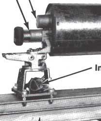
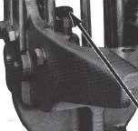
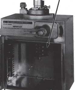
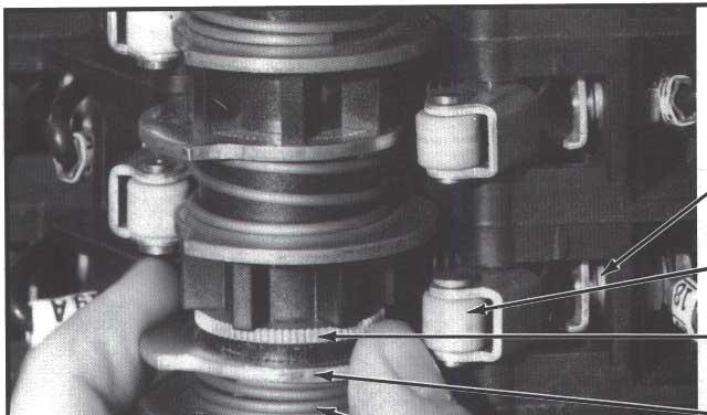
17 ~~~~ ~ ~~ ~ I FINAL CHECKS AND ADJUSTMENTS - Continued lies against its stop bolt in a positive-toggle condition, and the blade crank-arm at the top of each brain makes contact with its stop. See Step 11. If this is not the case, it will be necessary to isolate the poleunit(s) affected by loosening the clamp which fastens the pole-unit drive lever to the interphase shaft. Then, for each affected pole-unit, proceed as follows: (a) Loosen the four bolts fastening the brain to the rotating insulator stack. (b) Insert the %"-13X2%" positioning bolt through the tab and the stop bushing at the brain mounting flange and fasten securely, as described in Step 3. (c) Place the pole-unit drive lever against its stop bolt and tighten the clamp at the interphase shaft. Then tighten the four bolts which fasten the brain to the rotating insulator stack. (d) Remove the positioning bolt installed (b) above. If the above conditions are not met, contact the nearest S&C Sales Office for corrective instructions. Step 27 When operatiov is satisfactory, tighten the piercing set screws at all three pole-unit drive levers, piercing the pipe, and continue turning until a firm resistance is felt. Then verify that the clamp bolts and piercing set screws at all locations are fully tightened. Step 28 Crank the Line-Rupter to its fully open position and then to its fully closed position. In each position, set the corresponding "OPEN" and "CLOSED" position indicators at the output shaft of the manual geared operating handle (or at the output shaft of the switch operator). Step 29 If the S&C Manual Geared Operating Handle is furnished with an auxiliary switch, catalog number suffix "-Q" or "-W," it will be mounted inside the operating-handle enclosure, alongwith a terminal block for user's connections. See Figure 13. Each auxiliaryswitch contact is operated by a cam-actuated roller. A contact is closed if its roller is disengaged from a cam and, conversely, a contact is open if its roller is engaged by a cam. The cams are individually adjustable in 4.5-degree increments. Adjustment of the cams is accomplished as follows: (a) Raise (or lower) the cam toward its adjacent spring until the cam is separated from the teeth of the inner gear. See Figure 14. (b) Rotate the cam to advance or retard engagement with its roller. (c) Lower (or raise) the cam making sure that the teeth are in mesh with the inner gear. Step 30 Connect high-voltage conductors to their respective Line-Rupter terminal pads. Conductors must be de-energized and grounded in accordance with standard system operating practice. Step 31 Remove the container from each interrupter as follows: Remove and discard the Yi""16 zinc-plated serrated hex nuts which run the length of the container. Remove and discard the YLif-l6X7/S" and two %"-16X1" zinc-plated hex-head cap screws and flat washers which attach the upper container-half to the coupling end casting of the interrupter. Also remove and discard the three 3/S"-l6X%" and two %"-16X1" zinc-plated hex-head cap crews and flat washers which attach the upper container-half to the indicator end casting of the interrupter. Pry the cor.tainer-halves apart with a screwdriver. The upper container-half can now be removed and discarded-slotted holes are provided so that a rope or lifting sling can be attached and the container-half more conveniently lowered to the ground. Now remove and discard the 3/8"-16X7/g" hex-head cap screw and flat washer which attach the lower container-half to the coupling end casting of the interrupter, and the 3/""16X?/" hex-head cap screw and flat washer which attach the lower container-half to the indicator end casting of the interrupter. Then discard this container-half. Finally, remove and discard the foam-core inner liner wrapped around the iuterrupter. Now remove the shield for the pressure-relief device. step 32 Please complete and mail the Line-Rupter registration card! The information requested on this card is vital to ensure prompt notification in the event field modifications are needed. I INSTRUCTION SHEET S&C ELECTRIC 17 COMPANY Page Chicago of 17 S&C ELECTRIC LTD. CANADA Toronto December 16,1991 *
INSTRUCTIONS For Field Assembly and Installation
 nteger Style NSTRUCTONS For Field Assembly and nstallation [TABLE OF CONTENTS Section Page Number Section Page Number NTRODUCTON... 1 NSTALLATON... 7 BEFORE STARTNG NSTALLATON....5 FNA1,CHECKS... 10 1
INSTRUCTIONS. S&c Circuit-Switchers - Mark v Grounding Switches - 70,000 Amperes Momentary Outdoor Transmission I INTRODUCTION INSTRUCTION SHEET 7 1 1
 S&c Circuit-Switchers - Mark v Grounding Switches - 70,000 Amperes Momentary With 90-degree opening blades NSTRUCTONS - - - - - - - - - - - - - - For Field Assembly and nstallation NTRODUCTON CAUTON: The
Instructions for Installation and Operation
 S&C Alduti-Rupter Switches Outdoor Distribution Three-Pole Vertical-Break Style Reciprocating Operating Mechanism 25/34.5 kv and 34.5 kv Instructions for Installation and Operation TABLE OF CONTENTS Section
Installation and Operation
 S&C Series 2000 Circuit-Switchers Outdoor Transmission Model 2030 With Vertical Interrupters and Without Disconnect 69 kv through 230 kv Installation and Operation Table of Contents Section Page Section
Instructions for Installation and Operation
 S&C Alduti-Rupter Switches Three-Pole Side-Break Heavy-Duty Style Reciprocating Operating Mechanism 34.5 kv Instructions for Installation and Operation TABLE OF CONTENTS Section Page Section Page INTRODUCTION
Installation And Operation
 S&C Series 2000 Circuit-Switchers Outdoor Transmission Model 2020 With Vertical Interrupters and Side-Break Power-Operated Disconnect 69 kv through 138 kv Installation And Operation Table of Contents Section
INSTRUCTIONS. 1 Schematic. I Device ' I. S8C Switch Operators - Type CS-24. For Operation
 Number 38840R1-B. The NSTRUCTON S8C Switch Operators - Type CS-24 NSTRUCTONS For Operation CAUTON: The equipment covered by this publication must be operated and maintained by qualified persons who are
Installation. S&C Omni-Rupter Switches Outdoor Distribution 14.4 kv and 25 kv
 S&C Omni-Rupter Switches Outdoor Distribution 14.4 kv and 25 kv Three-Pole Side-Break Integer Style Hookstick-Operated Vertical and Tiered-Outboard Mounting Configurations Catalog Number Supplement R3
Product Specifications for Aluminum Vertical Break Switches
 1. General a) This specification covers the design, manufacture, and shipment of aluminum vertical break switches, both air-break and load-break configurations, for substation and transmission switching
Installation and Operation
 S&C Omni-Rupter Switches Outdoor Distribution 14.4 kv and 25 kv Three-Pole Side-Break Integer Style Hookstick-Operated Vertical and Tiered-Outboard Mounting Configurations Installation and Operation Table
Installation. S&C Omni-Rupter Switches Outdoor Distribution 14.4 kv and 25 kv
 S&C Omni-Rupter Switches Outdoor Distribution 14.4 kv and 25 kv Three-Pole Side-Break Integer Style Upright and Triangular Mounting Configurations Catalog Number Supplement R3 and Earliern Installation
INSTRUCTIONS For Field Assembly and Installation
 S%C Circuit-Switchers - Mark V Outdoor Transmission Vertical-Break Style 34.5 kv through 161 kv NSTRUCTONS For Field Assembly and nstallation TABLE OF CONTENTS Section Page Number Section Page Number NTRODUCTON....l
Installation and Operation
 S&C Alduti-Rupter Switches Outdoor Distribution (46 kv) Three-Pole Double-Break Integer Style Reciprocating Operating Mechanism No Catalog Number Supplement and Operation Table of Contents Section Page
Horizontal Circuit Switchers
 > Transformer Protection > CIRCUIT SWITCHERS C A T A L O G B U L L E T I N General Application Southern States Types CSH and CSH-B Horizontal Circuit Switchers provide an economical, versatile, space saving
Horizontal Circuit Switchers
 > Transformer Protection > CIRCUIT SWITCHERS C A T A L O G B U L L E T I N General Application Southern States Types CSH and CSH-B Horizontal Circuit Switchers provide an economical, versatile, space saving
SPECIFICATION BULLETIN
 SPECIFICATIONS Conditions of Sale STANDARD: Seller s standard conditions of sale set forth in Price Sheet 150 apply, except as modified under WARRANTY QUALIFICATIONS on page 3. SPECIAL TO THIS PRODUCT:
INSTRUCTIONS For Field Replacement
 SLC Source-Transfer PMH Pad-Mounted Gear Outdoor Distribution (14.4 kv and 25 kv) Replacing Type AT-12 Control With Micro-ATT Control In Gear Having R4 Supplement to the Catalog Number INSTRUCTIONS For
INSTRUCTIONS Ç CAUTION. S&C Power Fuses Types SMD-1A, SMD-2B, SMD-2C, and SMD-3. For Field Assembly and Installation NOTE INSTRUCTION SHEET
 S&C Power Fuses Types SMD-1A, SMD-2B, SMD-2C, and SMD-3 Outdoor Transmission Mountings Rated 34.5, 46, and 69 kv INSTRUCTIONS For Field Assembly and Installation TABLE OF CONTENTS Section Page Number INTRODUCTION........................................1
Instructions for Installation
 S&C Circuit-Switchers Mark VI Outdoor Transmission 69 kv through 138 kv Option U, User-Furnished Mounting Structure Instructions for Installation TABLE OF CONTENTS Section Page Section Page INTRODUCTION
Interrupter Replacement INSTRUCTIONS. For Replacement of Interrupters. A Cypo.qdated is the S&C trademark for devices employing the S&C Cypoxfl
 - - - S&C Alduti-Rupters Switches* Outdoor and ndoor Distribution nterrupter Replacement NSTRUCTONS - ~~~ - ~~ ~~ For Replacement of nterrupters [TABLE OF CONTENTS Page Section Section Number Page NTRODUCTON...
Product Specifications for Phase Over Phase GOABS(r)
") 1. General a) This specification covers the design, manufacture, and shipment of phase-over-phase, 1-way, 2-way, 3-way, and 4-way, gang-operated disconnecting switches, both air-break and load-break, for
1. General a) This specification covers the design, manufacture, and shipment of phase-over-phase, 1-way, 2-way, 3-way, and 4-way, gang-operated disconnecting switches, both air-break and load-break, for
S&C Circuit-Switcher Mark VI Outdoor Transmission (69 kv through 138 kv)
") Outdoor Transmission (69 kv through 138 kv) Construction Guide This publication sets forth the data required for the user to design a support structure or pedestals for a Mark VI Circuit-Switcher; the
Outdoor Transmission (69 kv through 138 kv) Construction Guide This publication sets forth the data required for the user to design a support structure or pedestals for a Mark VI Circuit-Switcher; the
Cleaning Flooded Gear
 S&C Manual PMX Modular Metal-Enclosed Switchgear Outdoor Distribution (13.8 kv and 25 kv) Cleaning Flooded Gear Table of Contents Section Page Section Page Introduction.... 2 Safety Information Understanding
Introduction CAUTION. S&C Power Operated Metal-Enclosed Switchgear Outdoor Distribution (4.16 kv, through 34.5 kv)
") S&C Power Operated Metal-Enclosed Switchgear Outdoor Distribution (4.16 kv, through 34.5 kv) Inspection Recommendations for Switchgear with Type AT-3 Source- Transfer Controls Table of Contents Section
S&C Power Operated Metal-Enclosed Switchgear Outdoor Distribution (4.16 kv, through 34.5 kv) Inspection Recommendations for Switchgear with Type AT-3 Source- Transfer Controls Table of Contents Section
Power & High Voltage Joslyn Hi-Voltage Overhead Reclosers & Switches H-220. Series HVI Hi-Velocity Interrupter Attachment
 Use load interrupter attachments to enable loop sectionalizing, line dropping, load breaking and transformer-magnetizing current interruption. Increase the capability of your disconnect switches by adding
Introduction CAUTION CAUTION. S&C Power Operated Metal-Enclosed Switchgear Indoor and Outdoor Distribution (4.16 through 34.5 kv)
") S&C Power Operated Metal-Enclosed Switchgear Indoor and Outdoor Distribution (4.16 through 34.5 kv) Inspection Recommendations for Switchgear Equipped with Type AT-2 Source-Transfer Controls Table of Contents
S&C Power Operated Metal-Enclosed Switchgear Indoor and Outdoor Distribution (4.16 through 34.5 kv) Inspection Recommendations for Switchgear Equipped with Type AT-2 Source-Transfer Controls Table of Contents
Cleaning Flooded Gear
 S&C Manual Metal-Enclosed Switchgear Indoor and Outdoor Distribution (4.16 kv through 34.5 kv) Cleaning Flooded Gear Table of Contents Section Page Section Page Introduction.... 2 Safety Information Understanding
15-kV Live Terminal 600 Amp Group Operated Pad-Mounted Metal-Enclosed Outdoor Switchgear 140 Amp (Max) Clip Mount Current-Limiting Fuses
 Clip Mount Current-Limiting Fuses") Page 1 2015 Heavy duty 11-gauge steel enclosure is all-welded construction for long life Corrosion proof nameplate is located to provide easy access for the operator Glass reinforced barriers meet NEMA
Page 1 2015 Heavy duty 11-gauge steel enclosure is all-welded construction for long life Corrosion proof nameplate is located to provide easy access for the operator Glass reinforced barriers meet NEMA
S&C Switch Operators Types AS-1A and AS-10
 S&C Switch Operators Types AS-1A and AS-10 Page 1 of 11 S&C Switch Operators - Types AS-1A and AS-10 Types AS-1A and AS-10 Switch Operators are high-speed operators expressly designed for power operation
S&C Mini-Rupter Switches Application The Standard Mounting Arrangement Scheme for S&C Mini-Rupter Switches Typical ED, reduced from full 11 size.
 S&C Mini-Rupter es Indoor Distribution (4.16 kv through 25 kv) Selecting Standard Mounting Arrangements for Manually Operated Styles Application The Standard Mounting Arrangement Scheme for S&C Mini-Rupter
S&C Trans-Rupter II Transformer Protector Outdoor Transmission (69 kv through 138 kv)
") S&C Trans-Rupter II Transformer Protector Outdoor Transmission (69 kv through 138 kv) Construction Guide This publication sets forth the data required for the user to design a support structure for the
S&C Trans-Rupter II Transformer Protector Outdoor Transmission (69 kv through 138 kv) Construction Guide This publication sets forth the data required for the user to design a support structure for the
INSTRUCTIONS. S&C Switch Operators - Type CS-1 A. For Operation INTRODUCTION
 S&C Switch Operators - Type CS-1 A NSTRUCTONS For Operation NTRODUCTON CAUTON: The equipment covered by this puelication must be operated and maintained by qualified persons who are thoroughly trained
S&C Circuit-Switchers Mark VI Installed on S&C Mounting Pedestals 84- through 102-inch Phase Spacing Outdoor Transmission (69 kv through 138 kv)
") S&C Circuit-Switchers Mark VI Installed on S&C Mounting Pedestals 84- through 102-inch Phase Spacing Outdoor Transmission (69 kv through 138 kv) Installation Table of Contents Section Page Section Page
S&C Circuit-Switchers Mark VI Installed on S&C Mounting Pedestals 84- through 102-inch Phase Spacing Outdoor Transmission (69 kv through 138 kv) Installation Table of Contents Section Page Section Page
SECTION AXIAL HVAC FANS
 SECTION 233413 - AXIAL HVAC FANS 1. PART 1 GENERAL 1.1. RELATED DOCUMENTS A. Drawings and general provisions of the Contract, including General and Supplementary Conditions and Division 01 Specification
Section SWITCHBOARDS. Introduction. Part 1 - General. Related Work
 Section 16435 - SWITCHBOARDS Introduction Part 1 - General Related Work Section 16070 Seismic Anchorage and Restraint Section 16075 Electrical Identification Section 16080 Power Distribution Acceptance
Specifications. S&C Switch Operators Types AS-1A and AS-10a. Conditions of Sale
 a Specifications Conditions of Sale STANDARD: Seller s standard conditions of sale set forth in Price Sheet 150 apply. SPECIAL TO THIS PRODUCT: INCLUSIONS: S&C Switch Operators Types AS-1A and AS-10 are
Installation. S&C Circuit-Switchers Mark VI 69-kV 51-inch Phase Spacing Single Pedestal Design Outdoor Transmission.
 S&C Circuit-Switchers Mark VI 69-kV 51-inch Phase Spacing Single Pedestal Design Outdoor Transmission Installation Table of Contents Section Page Section Page Introduction Qualified Persons....2 Read this
Specifications. S&C Omni-Rupter Switches Outdoor Distribution (14.4 kv and 25 kv) Conditions of Sale
 Conditions of Sale") S&C Omni-Rupter Switches Outdoor istribution (14.4 kv and 5 kv) Specifications Conditions of Sale STNR: Seller s standard conditions of sale as set forth in Price Sheet apply. SPECIL TO THIS PROUCT: INCLUSIONS:
S&C Omni-Rupter Switches Outdoor istribution (14.4 kv and 5 kv) Specifications Conditions of Sale STNR: Seller s standard conditions of sale as set forth in Price Sheet apply. SPECIL TO THIS PROUCT: INCLUSIONS:
INSTRUCTIONS For Installation
 S&C Switch Operators - Types LS- and LS-2 NSTRUCTONS For nstallation TABLE OF CONTENTS i Section Page Number Section Page Number NTRODUCTON... 1 NSPECTON SCHEDULE AND PROCEDURES....16 NSTALLATON... 3 CHECKNG
TRINETICS CSD SERIES OIL SWITCH INSTALLATION INSTRUCTIONS
 TRINETICS CSD SERIES OIL SWITCH INSTALLATION INSTRUCTIONS 33220900 DECEMBER 2011 Caution: The equipment covered by these installation instructions should be installed and serviced only by properly trained
Specifications. S&C Alduti-Rupter Switches with Power Fuses Outdoor Distribution (14.4 kv through 46 kv)
") Outdoor Distribution (4.4 kv through 46 kv) Specifications Conditions of Sale STANDARD: Seller s standard conditions of sale set forth in Price Sheet 50 apply, except as modified under WARRANTY QUALIFICATIONS
Outdoor Distribution (4.4 kv through 46 kv) Specifications Conditions of Sale STANDARD: Seller s standard conditions of sale set forth in Price Sheet 50 apply, except as modified under WARRANTY QUALIFICATIONS
INSTRUCTIONS. Section Page Number Section Page Number REMOVING THE MECHANICAL ANTIPARALLELING S&C ELECTRIC COMPANY 0 Chicago
 SBC Source-Transfer PMH Pad-Mounted Gear Outdoor Distribution (14.4 kv and 25 kv) Replacing Type AT-1 2 Control With Micro-AT Control n Gear Having Rl or R2 Supplement to the Catalog Number TABLE OF CONTENTS
Publication No.: PSG
 TABLE OF CONTENTS PAGE 1.0 SCOPE...2 2.0 STANDARDS...2 3.0 DESIGN REQUIREMENTS...2 3.01 Service Conditions... 2 3.02 Ratings... 3 3.03 Resistors... 3 3.04 Interrupter... 4 3.05 SF 6 Gas System... 4 3.06
Specifications. S&C Mini-Rupter Switches Indoor Distribution (4.16 kv through 25 kv) Manually Operated Styles
 Manually Operated Styles") Indoor Distribution (4.16 kv through 25 kv) Manually Operated Styles Specifications Conditions of Sale STANDARD: Seller s standard conditions of sale set forth in Price Sheet 150 apply, except as modified
Indoor Distribution (4.16 kv through 25 kv) Manually Operated Styles Specifications Conditions of Sale STANDARD: Seller s standard conditions of sale set forth in Price Sheet 150 apply, except as modified
SECTION CENTRIFUGAL HVAC FANS
 SECTION 233416 - CENTRIFUGAL HVAC FANS 1. PART 1 GENERAL 1.1. RELATED DOCUMENTS A. Drawings and general provisions of the Contract, including General and Supplementary Conditions and Division 01 Specification
15-kV Wall-Mount Switchgear Three-Phase Indoor/Outdoor 600 Amp S&C Mini-Rupter Switch
 Page 1 2015 Kinked roof prevents standing moisture Glass reinforced barriers meet NEMA GPO-3 Standards 0.625" diameter copper ground bar Elliott air-insulated bushings accept IEEE Standard inserts and
CONTENTS. This Product is Certified by CANADIAN STANDARDS ASSOCIATION and Bears the Mark:
 This Product is Listed by UNDERWRITERS LABORATORIES INC. and Bears the Mark: This Product is Certified by CANADIAN STANDARDS ASSOCIATION and Bears the Mark: SLATER SCD Installation Instructions For Self-Contained
S&C Vista Underground Distribution Switchgear
 S&C Vista Underground Distribution Switchgear Pad-Mounted, Vault-Mounted, and UnderCover Styles Instructions For Installation and Operation of Portable Motor Operator TABLE OF CONTENTS Section Page Section
INSTRUCTIONS For Installation
 S&C Switch Onerators - TyDe CS-PA NSTRUCTONS For nstallation TABLE OF CONTENTS i Section Page Number Section Page Number NTRODUCTON... 1 NSPECTON SCHEDULE AND PROCEDURES... 11 NSTALLATON....3 CHECKNG SWTCH
S&C Series 2000 Circuit Switchers Outdoor Transmission (69 kv through 230 kv)
") Outdoor Transmission ( kv through 230 kv) Terminal-Pad Loading Limits and Mounting-Pedestal Foundation Loading Data This publication sets forth the maximum-continuous and permissible peak loading limits
Outdoor Transmission ( kv through 230 kv) Terminal-Pad Loading Limits and Mounting-Pedestal Foundation Loading Data This publication sets forth the maximum-continuous and permissible peak loading limits
Product Specification Guide. Title: Southern States 72 kv RLSwitcher Vertical Interrupter Style Reactor Switcher
 TABLE OF CONTENTS PAGE 1.0 SCOPE... 2 2.0 STANDARDS... 2 3.0 DESIGN REQUIREMENTS... 2 3.01 Service Conditions... 2 3.02 Ratings... 3 3.03 Interrupter... 3 3.04 SF6 Gas System... 4 3.05 Terminal Pads...
INSTRUCTIONS For Field Assembly, Installation, and Maintenance
 INSTRUCTIONS For Field Assembly, Installation, and Maintenance TABLE OF CONTENTS Section Page Number INTRODUCTION........................................1 ASSEMBLING AND INSTALLING MOUNTINGS............2
The steering column is of a modular construction and features easy to service electrical switches.
 file://c:\tso\tsocache\vdtom_5368\svk~us~en~file=svkb4a01.htm~gen~ref.htm Page 1 of 3 Section 11-04A: Steering Column, Ranger DESCRIPTION AND OPERATION 1997 Ranger Workshop Manual Steering Column NOTE:
ichards MANUFACTURING COMPANY, SALES, INC. 517 LYONS AVENUE, IRVINGTON, NJ Phone Fax
 Network Protector Instruction Manual Type 316NP ichards MANUFACTURING COMPANY, SALES, INC. 517 LYONS AVENUE, IRVINGTON, NJ 07111 Phone 973-371-1771 Fax 973-371-9538 IM 1232-001B DISCLAIMER OF WARRANTIES
CENTER BREAK GROUP OPERATED AIR BREAK SWITCHES RATED 15.5kV THROUGH 170kV EFFECTIVE DATE: 10/25/16 REV B
 CENTER BREAK GROUP OPERATED AIR BREAK SWITCHES RATED 15.5kV THROUGH 170kV EFFECTIVE DATE: 10/25/16 REV B TCV2 Hubbell has a policy of continuous product improvement. Please visit hubbellpowersystems.com
IB-FAS3 Mar Type FAS THRU 115Kv Amp 61 KA Momentary. Vertical-Break, Gang-Operated Outdoor Air Disconnect Switch.
 IB-FAS3 Mar. 2014 Type FAS3 7.5 THRU 115Kv 600 1200 Amp 61 KA Momentary Vertical-Break, Gang-Operated Outdoor Air Disconnect Switch Page 0 Contents Subject Page Receiving and Handling................................................
Descriptive bulletin. Medium voltage load interrupter switchgear Reliable, low maintenance and economical for distribution applications
 Descriptive bulletin Medium voltage load interrupter switchgear Reliable, low maintenance and economical for distribution applications General overview Reliable, low maintenance and economical Load Interrupter
S&C Source-Transfer Vista Underground Distribution Switchgear
 S&C Source-Transfer Vista Underground Distribution Switchgear Pad-Mounted, Dry-Vault-Mounted, Wet-Vault-Mounted, and UnderCover Styles Instructions For Installation Section Page Section Page INTRODUCTION
S&C Series 2000 Circuit-Switchers Outdoor Transmission 69 kv through 230 kv
 S&C Series 2000 Circuit-Switchers Outdoor Transmission 69 kv through 230 kv Why do power users choose the Series 2000 Circuit-Switcher over any other circuit-switcher? Series 2000 Circuit-Switcher advances
Installation and Operation
 S&C Three-Shot Type XS Fuse Cutout Outdoor Distribution (4.16 kv through 15 kv) Installation and Operation Table of Contents Section Page Section Page Introduction Qualified Persons... 2 Read this Instruction
ROLLER GATES. Waterman Industries of Egypt. Roller gates are nominated for heavy duty service where large loads and sizes are going to be encountered.
 ROLLER GATES Roller Gates are ideally suited for controlling water in any large openings such as may be found in power plants, water and sewage treatment facilities, flood control projects, irrigation
Typical Specification
 Engineered to Order Built to Last Typical Specification VAULT VRPFI, TWO POSITION, ROTARY PUFFER SWITCHGEAR PART 1- GENERAL 1.1 DESCRIPTION A. The switch shall consist of manually operated load interrupting,
Installation, Operation, and Maintenance
 S&C Regulator Bypass Switches Outdoor Distribution (14.4 kv through 25 kv) Type XL (Sequenced) and Type NL (Non-sequenced) Installation, Operation, and Maintenance Table of Contents Section Page Section
ichards MANUFACTURING COMPANY, SALES, INC. 517 LYONS AVENUE, IRVINGTON, NJ Phone Fax
 Network Protector Instruction Manual Type 147NP 2250 to 4500 Amperes ichards MANUFACTURING COMPANY, SALES, INC. 517 LYONS AVENUE, IRVINGTON, NJ 07111 Phone 973-371-1771 Fax 973-371-9538 IM 1225-001B DISCLAIMER
Product Specification Guide. Title: Southern States 362 kv RLSwitcher Vertical Interrupter Style Reactor Switcher
 TABLE OF CONTENTS PAGE 1.0 SCOPE... 2 2.0 STANDARDS... 2 3.0 DESIGN REQUIREMENTS... 2 3.01 Service Conditions... 2 3.02 Ratings... 2 3.03 Interrupter... 3 3.04 SF6 Gas System... 4 3.05 Terminal Pads...
S&C Type FVR Substation Circuit Breaker
 S&C Type FVR Substation Circuit Breaker 15 kv to 38 kv, 200 kv BIL, 1200 A, Class 6065 Instructions for Installation 60553014 S&C ELECTRIC COMPANY Specialists in Electric Power Switching and Protection
S&C Manual PME Pad-Mounted Gear
 S&C Manual PME Pad-Mounted Gear Outdoor Distribution,. kv and 5 kv S&C Manual PME Pad-Mounted Gear... Featuring Elbow-Connected Encased Components. S&C Manual PME Pad-Mounted Gear brings in-air insulation,
COOPER POWER SERIES. Types D and DV recloser installation instructions. Reclosers MN280030EN
 Reclosers MN280030EN Effective December 2015 Supersedes S280-20-1 February 1979 Types D and DV recloser installation instructions COOPER POWER SERIES DISCLAIMER OF WARRANTIES AND LIMITATION OF LIABILITY
COOPER POWER SERIES. Types 4H single-phase and 6H three-phase vacuum interrupter conversion kits. Reclosers MN280014EN
 Reclosers MN280014EN Effective September 2015 Supersedes S280-10-6 April 2003 COOPER POWER SERIES Types 4H single-phase and 6H three-phase vacuum interrupter conversion kits DISCLAIMER OF WARRANTIES AND
INSTRUCTIONS. Operating Lever4 Maximum Operating
 S&C Switch Operators - Type CS-10 NSTRUCTONS 1 NTRODUCTON CAUTON: The equipment covered by this publication must be operated and maintained by qualified persons who are thoroughly trained and who understand
TABLE OF CONTENTS I. SERVICE & MAINTENANCE PROCEDURES. 1) Opening and closing of door latch. 2) Latch assembly and adjustment
 Opening and closing of door latch. 2) Latch assembly and adjustment") TABLE OF CONTENTS I. SERVICE & MAINTENANCE PROCEDURES 1) Opening and closing of door latch 2) Latch assembly and adjustment 3) Latch cover removal and replacement 4) Upper slider track adjustment 5) Lower
TABLE OF CONTENTS I. SERVICE & MAINTENANCE PROCEDURES 1) Opening and closing of door latch 2) Latch assembly and adjustment 3) Latch cover removal and replacement 4) Upper slider track adjustment 5) Lower
S&C Loadbuster Disconnect Switches. Outdoor Distribution (14.4 kv through 34.5 kv)
") S&C Loadbuster Disconnect Switches Outdoor Distribution ( kv through 34.5 kv) S&C s Loadbuster Disconnect Switches, when used with S&C s Loadbuster tool, provide the ultimate in distribution live-switching
S&C Loadbuster Disconnect Switches Outdoor Distribution ( kv through 34.5 kv) S&C s Loadbuster Disconnect Switches, when used with S&C s Loadbuster tool, provide the ultimate in distribution live-switching
Operators/Accessories. Type V2-CA Aluminum. Vertical Break Switch. Ordering Information Furnish: Available Accessories. Standard Operator Features
 Vertical Break Switch Operators/Accessories Ordering Information Furnish: Switch type Voltage Amperage Momentary rating BIL level Mounting position Operator type Accessories required Base mounting holes
Industrial Turbo Meters, Sizes 2" through 6"
 Industrial Turbo Meters Sizes 2" through 6" TUR-UM-00530-EN-19 (October 2014) User Manual Industrial Turbo Meters, Sizes 2" through 6" User Manual CONTENTS Scope of the Manual 5 Specifications 5 Product
Specification Pad-Mounted Capacitor Bank with Dual Fusing Integral Load-Interrupter on Line-Side Fuse Mountings
 Page 1 Specification Pad-Mounted Capacitor Bank with Dual Fusing Integral Load-Interrupter on Line-Side Fuse Mountings I. General This specification covers the design requirements for a pad-mounted capacitor
ProTrip Conversion Kits. For GE Types AK-15, AK-25, and AKU- 25 Low-Voltage Power Circuit Breakers INTRODUCTION. DEH Installation Instructions
 DEH 40026 Installation Instructions g ProTrip Conversion Kits For GE Types AK-15, AK-25, and AKU- 25 Low-Voltage Power Circuit Breakers INTRODUCTION GE Conversion Kits are designed for upgrading existing
DESIGN GUIDELINES LOW VOLTAGE SWITCHGEAR PAGE 1 of 5
 DESIGN GUIDELINES LOW VOLTAGE SWITCHGEAR PAGE 1 of 5 1.1. APPLICABLE PUBLICATIONS 1.1.1. Publications listed below (including amendments, addenda, revisions, supplements, and errata), form a part of this
Three-Phase Pole Mounted Recloser
 Three-Phase Pole Mounted Recloser Page 1 of 8 Table of Contents 1 GENERAL... 3 2 CONSTRUCTION... 3-5 3 BUSHINGS... 5 4 LINE CONNECTOR... 5 5 TOOLS....5 6 NAMEPLATES..6 7 PAINT... 6 8 EXTERNAL HARDWARE
TYPE AST. Grounding Switch. ALL Ratings INSTALLATION & INSTRUCTION MANUAL
 TYPE AST Grounding Switch ALL Ratings INSTALLATION & INSTRUCTION MANUAL The Quality Name in High Voltage Switching Page I The Quality Name in High Voltage Switching Safety Information Page II The Quality
www. ElectricalPartManuals. com INSTRUCTIONS "INERTEEN AND OIL INSULATED FEEDER SWITCHES DESCRIPTION INSTALLATION MAINTENANCE
 r \ FIG. 1. Cutaway View of Typical Switch. I.L. 46-723-1 DESCRIPTION INSTALLATION MAINTENANCE INSTRUCTIONS THE INERTEEN AND OIL INSULATED FEEDER SWITCH provides complete switching facilities in a minimum
2006 MINI Cooper S GENINFO Starting - Overview - MINI
 MINI STARTING SYSTEM * PLEASE READ THIS FIRST * 2002-07 GENINFO Starting - Overview - MINI For information on starter removal and installation, see the following articles. For Cooper, see STARTER WITH
Installation Instructions For Motor Control Center (MCC) Units
 Units") s Page 1 of 8 Installation Instructions December, 2013 Installation Instructions For Motor Control Center (MCC) Units Hazardous voltage. Will cause death or serious injury. Always de-energize and ground
s Page 1 of 8 Installation Instructions December, 2013 Installation Instructions For Motor Control Center (MCC) Units Hazardous voltage. Will cause death or serious injury. Always de-energize and ground
INSTALLATION, OPERATION AND MAINTENANCE MANUAL
 INSTALLATION, OPERATION AND MAINTENANCE MANUAL LUDLOW SERIES FIGURE 350-W 3 to 24 Lever & Weight Air-Cushioned Swing Check Valves TABLE OF CONTENTS Introduction. 1 Description of Operation... 1 Receiving
C1000 Series Automatic Cap Bank
 C1000 Series Automatic Cap Bank Metal Enclosed - Medium Voltage Capacitors Assemblies Fixed / Auto Medium Voltage 5, 15, 25 and 35 kv Class Customized to your specifications The Reactive Power Solution
ISO Rules Part 500 Facilities Division 502 Technical Requirements Section Interconnected Electric System Protection Requirements
 Applicability 1 Section 502.3 applies to: the legal owner of a generating unit directly connected to the transmission system with a maximum authorized real power rating greater than 18 MW; the legal owner
S&C Loadbuster Disconnects
 S&C Loadbuster Disconnects Outdoor Distribution ( kv through 34.5 kv) With these outstanding features... Up to -ampere continuous ratings, 40,000-ampere RMS asymmetrical momentary ratings Designed for
Switch Base Replacement Instructions 3-Pole, 60 AMP, Fusible, w Neutral, Visible-Blade, Heavy Duty Safety Switches
 Step Switch Base Replacement Instructions 3-Pole, 60 AMP, Fusible, w Neutral, Visible-Blade, Heavy Duty Safety Switches Work Description All work should be performed in accordance with NFPA 70E. Tools
Operator s Manual Series ATB Automatic Transfer & Bypass Isolation Switches 150, 260, and 400 amp sizes A. Rating Label.
 Operator s Manual 7000 Series ATB Automatic Transfer & Bypass Isolation Switches 150, 260, and 400 amp sizes TABLE OF CONTENTS Note: Refer to the outline and wiring drawings provided with your 7000 Series
Valtek Auxiliary Handwheels and Limit Stops
 Valtek Auxiliary s and Limit Stops Table of Contents Page 1 General information 2 Installation 2 Side-mounted handwheels, size 25 and 50 (linear actuators) 3 Side-mounted handwheels, size 100 and 200 (linear
KFE10010-E. Reclosers. Contents. Type KFVE and KFVME (27kV) Bus Bar Kit KRK710-1 Installation Instructions. Cooper Power Systems
 Bus Bar Kit KRK710-1 Installation Instructions. Cooper Power Systems") Reclosers Type KFVE and KFVME (27kV) Bus Bar Kit KRK710-1 Installation Instructions Cooper Power Systems Service Information Figure 1. Type KFVE and KFVME (27kV) bus bar kit KRK710-1. 961047KM Contents
Reclosers Type KFVE and KFVME (27kV) Bus Bar Kit KRK710-1 Installation Instructions Cooper Power Systems Service Information Figure 1. Type KFVE and KFVME (27kV) bus bar kit KRK710-1. 961047KM Contents
Brake Shoe: Service and Repair Removal Procedure
 2000 Buick Century V6-3.1L VIN J Copyright 2013, ALLDATA 10.52 Page 1 Brake Shoe: Service and Repair Removal Procedure ^ Tools Required - J38400 Brake Shoe Spanner and Spring Remover Caution: Keep fingers
VersaRupter 5-38 kv Load Interrupter Switch. Technical Guide
 VersaRupter 5-38 kv Load Interrupter Switch Technical Guide NOTICE Components in this catalog are intended for use by switchgear assemblers engaged in original equipment manufacturing. All sales are subject
MODEL ELC-12/40-CVM-D BATTERY CHARGER
 NATIONAL RAILWAY SUPPLY MODEL ELC-12/40-CVM-D BATTERY CHARGER Installing, Operating and Service Instructions for the ELC-12/40-CVM-D Solid State Charger PLEASE SAVE THESE IMPORTANT SAFETY AND OPERATING
INSTALLATION INSTRUCTIONS AMBASSADOR DRUM OVERHEAD SERIES 100 DUMBWAITER
 INSTALLATION INSTRUCTIONS AMBASSADOR DRUM OVERHEAD SERIES 100 DUMBWAITER The installation of Matot Drum Dumbwaiters should only be performed by qualified, experienced, and trained elevator installers.
Unitized Quick Install Switches for Substation Applications
 Bulletin DB-680A15 Unitized Quick Install Switches for Substation Applications CLEAVELAND / PRICE INC. 14000 Rt. 993, Trafford, PA 15085 (724) 864-4177 FAX (724) 864-9040 Email: sales@cleavelandprice.com
SECTION ENCLOSED SWITCHES AND CIRCUIT BREAKERS
 SECTION 26 28 16 ENCLOSED SWITCHES AND PART 1 - GENERAL 1.1 SUMMARY A. Section includes the following individually mounted, enclosed switches and circuit breakers rated 600V AC and less: 1. Fusible switches.
XChange Seat Service and Maintenance Guide
 XChange Seat Service and Maintenance Guide Table Of Contents Page General Information... 1 Registration Information... 1 Seat Cushion Latch... 2 Lap Shoulder Belt Replacement... 2 Sliding Buckles Replacement...
S&C Alduti-Rupter Switches. Outdoor Distribution, 14.4 kv through 69 kv
 S&C Alduti-Rupter Switches Outdoor Distribution, 14.4 kv through 69 kv Application S&C Alduti-Rupter Switches, rated 14.4 kv through 69 kv, 600 amperes or 1200 amperes continuous and live switching, provide
Specifications. S&C Alduti-Rupter Switchesa Indoor Distribution (4.8 kv through 34.5 kv) Conditions of Sale SPECIAL TO THIS PRODUCT: How to Order
 Conditions of Sale SPECIAL TO THIS PRODUCT: How to Order") S&C Alduti-Rupter Switchesa Indoor Distribution ( kv through kv) Specifications Conditions of Sale STANDARD: Seller s standard conditions of sale set forth in Price Sheet 0 apply. SPECIAL TO THIS PRODUCT:
S&C Alduti-Rupter Switchesa Indoor Distribution ( kv through kv) Specifications Conditions of Sale STANDARD: Seller s standard conditions of sale set forth in Price Sheet 0 apply. SPECIAL TO THIS PRODUCT:
The Standard Mounting Arrangements for S&C Alduti-Rupter Switches
 S&C Alduti-Rupter Switches Outdoor Distribution (14.4 kv through 69 kv) The Standard Mounting Arrangements for S&C Alduti-Rupter Switches Three-pole S&C Alduti-Rupter Switches for outdoor distribution