INSTRUCTIONS For Installation
|
|
|
- Dominic Rodgers
- 5 years ago
- Views:
Transcription

1 S&C Switch Operators - Types LS- and LS-2 NSTRUCTONS For nstallation TABLE OF CONTENTS i Section Page Number Section Page Number NTRODUCTON... 1 NSPECTON SCHEDULE AND PROCEDURES NSTALLATON... 3 CHECKNG SWTCH OPERATOR AND HGH-VOLTAGE MANUALOPERATON... 6 SWTCH POSTONS ADJUSTMENTS... 8 NTRODUCTON The equipment covered by this publication must be selectedforaspecificapplication and it mustbe installed, operated, and maintained by qualified persons who are thoroughly trained and who understand any hazards that may be involved. This publication is written only for such qualified persons and is not intended to be a substitute for adequate training and experience in safety procedures for this type of equipment. The S&C Switch Operator-Type LS-1 is a low-speed operator (with an operating time of 4 to 7 seconds) expressly recommended for power operation of outdoor high-voltage disconnects and interrupter switches not of S&C manufacture, for which this low operating speed is appropriate. The S&C Switch 0perator Type LS-2 is a high-speed operator (with a maximum operating time of 2.2 seconds) especially designed for power operation of S&C Line-Rupters. For power operation of S&C Alduti-Ruptere Switches-Outdoor Distribution, S&C Switch Operators-Types M-lA and As-10 are offered. For power operation of S&C Circuit-Switchers, S&C Switch Operators-Types CS-lA, CS-2A, and CS-10 are available. S&C Switch Operators-Types LS-1 and LS-2 include the following features as standard: Built-in internal decoupling mechanism, operable by integral external selector handle, with padlocking provisions and automatic mechanical locking of output shaft. Laminated safety-plate window permits visible air-gap verification of complete disengagement of output shaft. 0 Open-close pushbuttons, externally operable, with padlockable cover. SWTCH OPERATORS-Types LS-1 and LS-2 High-Voltage Device Application Rating of High-Voitage Device Switch Operator Type Ma;? Control Voltage Operating lime, Seconds@ Minimum Locked-Rotor Maximum Torque at RaledControl Voltage, inch-lbr. :r:; Number Schematic Wiring Diagram Drawing Number Outdoor Disconnects and 7,2 kv thru 48 v dc R1-A interrupter Swltches LS-1 4 to 7* CDR kv Not of S8C Manufacture 125 v dc R1-0 S8C Line-Rupters kvthru 48 v dc A 30 Ls CDR kv v dc Basedonminunumbatteryand external control w e sue requirements Depending on torquerequirements of the dlsconnect or interrupter specified n S&C Data Bulletin operating time wil be less if larger- switch, and assuming 180-degree vertical-pipe rotation. than-mlnimum battery sue and/or external control wire size is utilized Supersedes lnstructlon Sheet dated NSTRUCTON SHEET COMPANY ELECTRC S&C Page Chicago 1 of 18 S&C ELECTRC CANADA LTD. September Toronto 7,1993

2 ~ ~~ S&C Switch Operators - Types LS- and LS-2 NTRODUCTON - Continued 0 Built-in nonremovable, foldaway manual operating handle. 0 Mechanical position indicators for both switch operator and high-voltage switch "open" and "closed" positions. 0 Non-reset electric operation counter. 0 Laminated safety-plate window for inspection of built-in internal decoupling mechanism, mechanical position indicators, and operation counter (and position-indicating lamps, if furnished as accessories). 0 Foolproof recoupling. mpossible with positionindexing drums to couple the switch operator and the high-voltage switch "unsynchronized." 0 Fingertip precision adjustment of limits of outputshaft rotation (adjustable over a 35- to 235-degree range) using self-locking spring-biased cams. 0 Eight-pole auxiliary switch, coupled to motor, with fmgertip precision adjustment of individual contacts using self-locking spring-biased cams. Antifriction bearings throughout; tapered roller bearings for all high-torque gear-train shafts. 0 Two-pole pull-out fuseholders for motor circuit and space-heater circuit. Weatherproof, dustproof enclosure, equipped with 120/240-volt ac space heater, factory-connected for 240-volt ac operation. Can readily be field reconnected for 120-volt ac operation. 0 Tamper-resistant design-welded enclosure; baffled louvers; gasketed, flanged door openings; cam-action door latch; provisions for padlocking. Foul-weather accessibility to interior of enclosure. Access is by door rather than by removal of entire enclosure. 0 Flexible coupling, to connect switch operator output shaft to vertical operating pipe of disconnect or interrupter switch (%", 2", 2M", or 3" PS, as specified). Switch operator catalog numbers are suffied with one or more letters. The first letter following the catalog number designates the motor and control voltage: suffii -A -B Voltage 48 volts dc 125 volts dc Other suffm letters which may be added to the switch operator catalog number indicate the inclusion of optional accessories as follows: ACCESSORES tem Suffix Added to Switch Operator Catalog Number Deletion of Externally Operable Open-Close Pushbuttons -J Space Heater Thermostat -K Key nterlock wlth Swltch, locks high-voltage swltch open and disconnects motor-control ctrcult Posltton-lndlcating Lamps (one red, one green), mounted inside the enclosure Extra Auxihary Switch (mdlvldually adjustable contacts), 4-PST (coupled to motor) Duplex Receptacle and Convenlence-Light Lampholder with Swltch Extra Auxlllary Swltch (indlvldually adjustable contacts), 8-PST (coupled to high-voltage switch)@ Remote-Control Blocking Switch, prevents remote operatlon of switch operator when the protective cover for the externally mounted open-close pushbuttons is open 1 Extra Auxlhary The 8-PST extra auxaary switch (suffix "-W) cannot be furnlshed if the 12-PST versmn (suffur "-Zm) is specified. and me versa (ndividually adjustable contacts), 12-PST (coupled to high-voltage switch)@ -Z -L " -Q -V -W -Y NSTRUCTON SHEET Page 2 of 18 S&C COMPANY ELECTRC S&C CANADA ELECTRC Chicago LTD. 0 Toronto


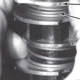
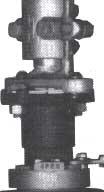
3 1 NSTALLATON step 1 Bolt the switch operator in position with %-inch mounting hardware, using any two of the four holes in each of the mounting angles at the rear of the switch operator. Step 2 Attach, to the switch operator output shaft, the flexible coupling furnished for the vertical operating pipe. See Figure 1. Thread the attachment bolts through the flexible coupling plate and through the coupling flange on the output shaft. Tighten the bolts to draw the flexible plate flush against the flangt; this will deform the threads in the flexible plate, resulting in a binding, nonslip connection. nstall and tighten the self-locking nuts. & not use lockwashers with thejlexible coupling attachment bolts. Remove the clamp bolts and set aside the detachable half of the flexible coupling. step3 Place the high-voltage switch pole-units in their fully closed positions. nstall the interphase and verticaloperating-pipe sections. However, at the switch operator, do not attach the vertical pipe section to the switch operator output shaft until so directed in Step 9. Attachment bolt Flexible coupling plate Vertical operating lamp bolts Switch output Flexible coupling High-voltage-switch position indicators Self-locking nut Alignment arrow cover Manual operating handle (in storage position) Door handle- Selector handle L Switch operator nameplate Figure 1. Exterior view of switch operator. Chicago S&C ELECTRC CANADA LTD. Toronto NSTRUCTON SHEET Page3of 18


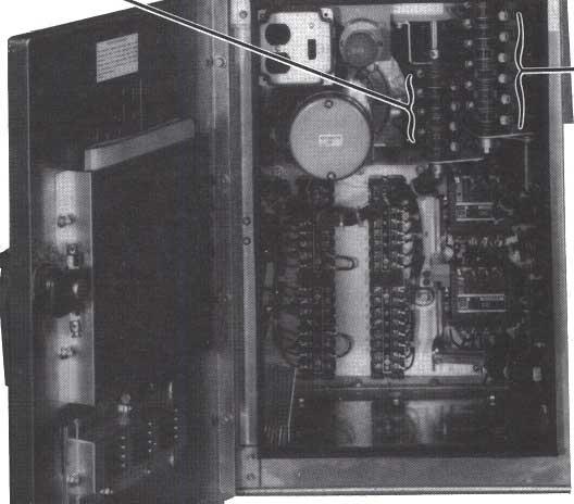
 \ Operation counter Remote-control blocking switch (Catalog Number Suffix -Y ) Position-indexing Open-close pushbuttons - Travel-limit switch, 2-PST (not visible")
 Motor contactor, opening Motor contactor, closing Conduit-entrance plate Figure 2. interior views of switch operator.")
4 S&C Switch Operators- Types M-1 and LS-2 Step 4 Mark the conduit-entrance location for the controlcircuit wiring on the conduit-entrance plate in the bottom of the switch operator enclosure. See Figure 2. Remove the conduit-entrance plate and cut out the required opening. Replace the plate and make up the entrance fittings. Apply sealing compound (provided with each switch operator) when replacing the conduitentrance plate. Verify that the entrance fittings are properly sealed to prevent water ingress. Step 5 To avoid accidental energizing of the operator after the external connections have been completed, remove the two-pole pull-out fuseholders for the motor circuit and space-heater circuit. See Figure 2. Reinsert the fuseholders only when indicated in the steps which follow. Remove the blocking from the motor contactors. Pushbutton protective cover (open) \ Operation counter Remote-control blocking switch (Catalog Number Suffix -Y ) Position-indexing Open-close pushbuttons - Travel-limit switch, 2-PST (not visible Arrow plate Auxiliary switch, 8-PST Extra auxiliary switch, / 8-PST (Catalog Number Suffix -W ); 1%PST version (Catalog Number Suffix -Z ) is similar. Extra auxiliary switch, 4-PST (Catalog Number Suffix 42 ) Motor contactor, opening Motor contactor, closing Conduit-entrance plate Figure 2. interior views of switch operator.. Motor-circuit two-pole E pull-out fuseholder - (control-source fuses and two-pole controlsource disconnect switch on earlier models) Manual operating handle interlock switch and mechanical blocking rods NSTRUCTON SHEET Page 4 of 18 S&C ELECTRC COMPANY Chicago * S&C ELECTRC CANADA LTD. Toronto


 Duplex receptacle and convenience-iiqht iamp-holder with swi&h (Catalog Number Suffix 4 ) Position-indicating lamps (Catalog Number Suffix -M )")
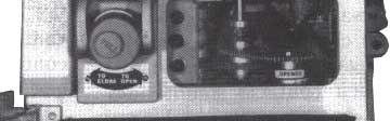
5 1 NSTALLATON - Continued C&nect the external control-circuit wiring (including space-heater source leads) to the terminal blocks of the switch operator in accordance with the wiring diagram furnished. ments for the control-circuit wiring, as shown in S&C Data Bulletin and on the switch operator schematic wiring diagram furnished. Unauthorized changes should not be made in the wiring of this switch operator. Should a controlcircuit revision appear desirable, it should be made only on the authority of a revised wiring diagram which has been approved by both the user and S&C Electric Company. Pushbutton protective cover (closed) Duplex receptacle and convenience-iiqht iamp-holder with swi&h (Catalog Number Suffix 4 ) Position-indicating lamps (Catalog Number Suffix -M ) instruction manual and holder -Q Space-heater circuit A two-pole pull-out fuseholder (space heater fuses on earlier models) Brake-release solenoid \ Terminal block Filter holder Space heater Door gasket S&C ELECTRC COMPANY Chicago S&C ELECTRC CANADA LTD. Toronto NSTRUCTON SHEET Page 5 of 18 September 7,1883

.")


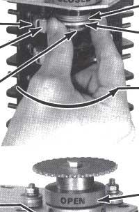
6 S&C Switch Operators - Types M-1 and LS-2 MANUAL OPERATON Before proceeding further, the user should become familiar with the operation of the manual operating handle and the selector handle, as described on the switch operator nameplate on the right-hand side of the enclosure and in the following Steps 6, 7, and 8. See Figures 3 and 4. Manual operation of the switch operator to open or close an energized disconnect switch or interrupter switch is not recommended. The reduced operating speed, due to hand cranking, will shorten the life of, and may damage, the arcing horns (or interrupting units). f switch operater control voltage is not available and high-voltage circuit conditions permit emergency manual opening, crank the manual operating handle rapidly and continuously through its full travel. Manual closing of an energized disconnect switch or interrupter switch should be avoided because of the possibility of closing into a fault. Step 6 To operate manually: Pull the latch knob on the hub of the manual operating handle and pivot the handle forward slightly from its storage position. Release the latch knob while continuing to pivot the handle forward to lock it into the cranking position. See Figure 3. (As the handle is pivoted forward, the motor brake is mechanically released, both leads of the control source are automatically disconnected, and both the opening and closing motor contactors are mechanically blocked in the open position.) f desired, during manual operation, the switch operator may also be disconnected from the control source by removing the motor-circuit two-pole pull-out fuseholder, located on the right-hand inside wall of the enclosure. To return the manual operating handle to its storage position, pull the latch knob and pivot the handle approximately 90 degrees. The handle will then be disengaged from the switch operator and may be rotated freely in either direction to its storage position. Piercing set screws Vertical operating Flexible coupling Manual operating handle Selector handle Latch knob Switch operator nameplate Figure 3. Manual operation Page 6 of 16 NSTRUCTON SHEET S&C ELECTRC COMPANY Chicago - S&C ELECTRC CANADA LTD. Toronto wfl


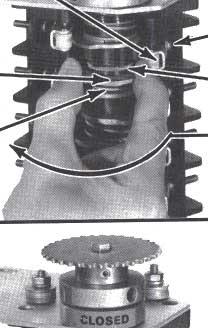
7 MANUAL OPERATON - Continued Complete the handle storage by pivoting the operating handle backward approximately 90 degrees until it latches in the storage position. Note that the manual operating handle may be disengaged from the switch operator mechanism at any position of the handle. The handle may be padlocked in its storage position. Step 7 To decouple: The integral external selector handle, for operation of the built-in internal decoupling mechanism, is located on the right-hand side of the switch operator enclosure. See Figure 3. Swing the selector handle upright and slowly rotate it clockwise 50 degrees to the decoupled position. See Figure 4. This decouples the switch operator mechanism from the switch operator output shaft. Then lower the selector handle to engage the locking tab. When thus decoupled, the switch operator may be operated either manually or electrically without operating the high-voltage switch. When the selector handle is in the decoupled position, the output shaft is prevented from moving by a mechanical locking device located within the switch operator enclosure. During the intermediate segment of the selector handle travel, &rich includes the position at which actual disengagement (or engagement) of the internal decoupling mechanism occurs, the motorcircuit source leads are momentarily disconnected and both the opening and closing motor contactors are mechanically blocked in the open position. Visual inspection, through the observation window, will verify whether the internal decoupling mechanism is in the coupled or decoupled position. See Figure 5. The selector handle may be padlocked in either position. for the high-voltage switch, located on the output-shaft collar of the switch operator, will be aligned later.) To move the switch operator to the exact position for coupling, turn the manual operating handle slowly until the position-indexing drums are, numerically aligned. Then swing the selected, handle upright and rotate it counterclockwise to the coupled position. Lower the handle to engage the locking tab. The selector handle is now in the coupled position. Selector handle (being turned to decoupled position) tabs step 8 To couple: Manually operate the switch operator to bring it to the same position (open or closed) as the high-voltage switch. The switch operator position indicator, seen through the observation window, will show when the approximate open or closed position has been attained. See Figure 5. (The position indicator Figure 4. Seleclor handle operation. ed S&c ELECTRC COMPANY Chicago S&C ELECTRC CANADA LTD. Toronto NSTRUCTON SHEET Page 7 of 16


8 S&C Switch Operators- Types B-1 and LS-2 ADJUSTMENTS Step 9 To avoid accidental energizing of the operator, remove the two-pole pull-out fuseholders for the motor circuit and space-heater circuit and do not 1 reinsertthem until so directed. 1 Make certain that the main contacts on all highvoltage switch pole-units are fully closed. With the selector handle in the coupled position, manually crank the switch operator to the fully closed position as indicated by the switch operator position indicator. See Figure 5. At the switch operator output shaft, replace the detachable portion of the coupling clamp. Make certain that the cutting tips of the piercing set screws do not protrude through the body of the coupling. Torque the flexible coupling clamp bolts equally to final tightness, so that the clamp pulls down evenly on the vertical operating-pipe section. Then tighten the associated piercing set screws, piercing the pipe, and continue turning until a firm resistance is felt. See Figure 3. Step 10 With the selector handle in the coupled position, crank the high-voltage switch to the fully open position, then to the fully closed position, and in each position accurately align the high-voltage-switch position indicators on the output-shaft collar of the switch operator with the alignment arrow below. See Figure 1. Each high-voltage-switch position indicator can be shifted after loosening the hex-head screws which fasten it to the output-shaft collar. Tighten these screws after making the above alignments. step 11 The cranking direction to close the high-voltage switch is indicated by an arrow plate located near the hub of the manual operating handle. See Figure 5. n the event that the cranking direction required to close the high-voltage switch is opposite to that indicated by the arrow plate, remount the arrow plate exposing its opposite side. (Direction of motor rotation will be checked in Step 13.) Temporarily mark on the top of the switch operator enclosure the direction in which the output shaft rotates to close the high-voltage switch. step 12 Place the selector handle in the decoupled position in preparation for electrical operation. - - Position-indicating lamps (Catalog Number Suffix -M ) Position-indexing r drums T-T- -Operation counter nternal decoupling mechanism (in coupled position) :mj Selector handle (in deco Jpled position) nternal decoupling mechalism (in decoupled position) Switch operator position indicators Figure 5. Views of switch operator through observation window Page 6 of 16 NSTRUCTON SHEET S&C ELECTRC COMPANY Chicago - S&C ELECTRC CANADA LTD. Toronto

9 JADJUSTMENTS Step 13 With the manual operating handle in its storage position and the selector handle in the decoupled position, reinsert the motor-circuit fuseholder. Open the pushbutton protective cover. and operate the switch operator by means of the externally mounted Open- Close pushbuttons, if provided, or, in their absence, by momentarily jumpering terminals 1 and 8 to open, and 1 and 9 to c1ose.a Note the direction in which the travel-limit cams rotate when the switch operator closes. This direction should agree with the temporary direction mark previously made on the top of the enclosure. (As a matter of information, the direction of rotation of the travel-limit cams is always the same as the direction of rotation of the output shaft.) n the event that the direction of rotation of the travel-limit cams (as noted above) is opposite to the temporary direction mark previously made on the top of the enclosure, a reversal of the motor direction wil be necessary. Remove the motor-circuit fuseholder to avoid accidental or remote energization of the control circuit. nterchange the Sl and S2 motor leads connected to terminals 4 and 5 on the terminal block in the switch operator enclosure. t should be noted particularly that reversal of the motor direction reverses only the direction of rotation of the output shaft and travel-limit cams. The identity of the opening-stroke and closing-stroke travel-limit cams (which will be adjusted later) will remain unaffected. Step 14 The travel-limit switch (coupled to the motor), which governs the extent of output-shaft rotation in the opening and closing directions, includes two contacts that are operated by cam-actuated rollers. See Figure 6. The cams (upper one is the opening-stroke travel-limit cam; and the one immediately below is the closingstroke travel-limit cam) are individually adjustable in 4.5-degree increments. Therefore, each cam can be adjusted to advance or retard engagement with its roller and thus open or close the corresponding switch contact, as desired, during motor operation. Advancing a cam advances roller engagement to de-energize the corresponding motor contactor earlier and thus decreases the extent of output-shaft rotation. Conversely, retarding a cam retards engagement with its roller to delay de-energization of the corresponding motor contactor and thus increases the extent of output-shaft rotation. The travel-limit cams (aswell as the auxiliary-switch cams) are to be adjusted as directed in Steps 15 through 20 using the following procedure (do not make any adjustments at this time): (a) Remove the motor-circuit fuseholder. (b) Raise (or lower) the cam toward its adjacent spring until the cam is separated from the teeth of the inner gear. (c) Rotate the cam to advance or retard engagement with its roller. See Figures 6 and 7. Advance the cam to decrease travel. Retard the cam to increase travel. (d) Lower (or raise) the cam making sure that the teeth are in mesh with the inner gear. Preliminary Adjustment of Travel-Limit Cams Step 15 The adjustments described in this step are necessary only if: (a) The switch operator output-shaft rotation (adjustable over a 35- to 235-degree range) was not factory set for the specific requirement of this installation; and/or (b) A reversal of the motor direction was required, as described in Step 13. Closing-Stroke Travel-Limit Cam. Place the selector handle in the coupled position. Manually operate the switch operator in the closing direction and observe the closing-stroke travel-limit cam. At the completion of the switch operator closing stroke, the leading edge of the closing-stroke travel-limit cam should be engaged with its associated roller. f the leading edge is not engaged with its roller, adjust the closing-stroke travellimit cam (asdescribed in Step 14) so that its leading edge touches (or nearly touches) the roller. Opening-Stroke Travel-Limit Cam. With the selector handle in the coupled position, manually operate the switch operator in the opening direction and observe the opening-stroke travel-limit cam. At the completion of the switch operator opening stroke, the leading edge of the opening-stroke travel-limit cam should be engaged with its roller. f the leading edge is not engaged with its roller, adjust the opening-stroke travel-limit cam (asdescribed in Step 14) so that its leading edge touches (or nearly touches) the roller. Return the manual operating handle to its storage position. For switch operators with optlonal remote-control blocking switch (suffix -Y), opening the pushbutton protectivecoverpreventsremote operation of the switch operator. A Termmal designations may dif er in special wiring diagrams. n such cases, refer to the specific wiring diagram for the correct terminal designations. NSTRUCTON SHEET S&C ELECTRC COMPANY Page Chicago 9 of 18 S&C CANADA ELECTRC LTD. Toronto


10 -


11
 and the open stops on the high-voltage switch. t is likely that full opening and closing travel wil not have been attained.")
12 SBC Switch Operators - Types LS-1 and LS-2 ADJUSTMENTS - Continued Operate the switch operator electrically to open and close the high-voltage switch. Observe the toggle mechanisms (if applicable) and the open stops on the high-voltage switch. t is likely that full opening and closing travel wil not have been attained. This is because the travel-limit cams were adjusted to limit the extent of output-shaft rotation while the switch operator was in the decoupled position-i.e., in a noload condition. To attain full stop positions (and overtoggle positions, where applicable) of the highvoltage switch, refer to Figure 6 and proceed as described below. Closing-Stroke Travel-Limit Cam. f full closing of the high-voltage switch was not attained, replace the motor-circuit fuseholder and operate the switch operator electrically to open the high-voltage switch. Remove the motor-circuit fuseholder. To increase travel in the closing direction, retard the closing-stroke travel-limit cam one 4.5-degree increment (1) in the clockwise direction if the travel-limit cam and output shaft rotate clockwise to open the highvoltage switch; or (2) in the counterclockwise direction if the travel-limit cam and output shaft rotate counterclockwise to open the high-voltage switch. Replace the motor-circuit fuseholder and operate the switch operator electrically to close. f full closing travel has not been attained, repeat the procedure described above until full closing travel is attained. Opening-Stroke Travel-Limit Cam. f full opening of the high-voltage switch was not attained, operate the switch operator electrically to close the switch. Remove the motor-circuit fuseholder. To increase travel in the opening direction, retard the opening-stroke travel-limit cam one 4.5-degree increment () in the counterclockwise direction if the travel-limit cam and output shaft rotate clockwise to open the high-voltage switch; or (2) in the clockwise direction if the travel-limit cam and output shaft rotate counterclockwise to open the high-voltage switch. Replace the motor-circuit fuseholder and operate the switch operator electrically to open. f full opening travel has not been attained, repeat the procedure described above until full opening travel is attained. Step 18 When travel-limit cam adjustments have been completed, it may be necessary to realign the high-voltageswitch position indicators on the switch operator output-shaft collar with the alignment arrow. With the switch operator in the fully open position and then in the fully closed position, check the corresponding switch operator position indicator. n each position, the corresponding position indicator should be readilyvisible from the front of the enclosure. f adjustment of either position indicator is necessary, remove the motor-circuit fuseholder, loosen the two set screws on the position indicator, and rotate the position indicator to the desired position. Retighten the set screws. See Figure 8. step 19 The auxiliary switch, which is permanently coupled to the motor, includes eight contacts (terminals 11 through 26). f the optional position-indicating lamps are included, six contacts are available (terminals 13 through 18 and 21 through 26). These contacts are provided so that external circuits can be established to monitor switching operations. Each contact is operated by a cam-actuated roller. The cams are individually adjustable in 4.5-degree increments. Adjustment of the cams is accomplished in a manner identical to that indicated in Step 14 for the travellimit cams. The standard configuration for the auxiliary switch consists of four al contacts (terminals 11 through 18) and four bl contacts (terminals 19 through 26). 753=5m NSTRUCTON SHEET. Page 12 of 18 S&C ELECTRC COMPANY Chicago S&C ELECTRC LTD. CANADA Toronto

13 1 ADJUSTMENTS - Continued Thus, with the high-voltage switch in the open position, the al contacts are open and the 41 contacts are closed. Conversely, with the high-voltage switch in the closed position, the al contacts are closed and the bl contacts are open. A contact is closed if its roller is disengaged from a cam and, conversely, a contact is open if its roller is engaged by a cam. See Figure 8. Any auxiliary-switch contact being used must be checked for proper operation after the switch operator travel-limit cams have been adjusted. Check the auxiliary-switch contacts for both the open and closed positions of the high-voltage switch. f necessary, adjust the cams as described in Step 14 so that the auxiliaryswitch contacts are in the desired open or closed position (i.e., cam engaged with roller, or cam disengaged from roller). See Figure 7. Since each cam can be individually adjusted in 4.5-degree increments, any al contact can be changed to a bl contact, or vice versa. Also, because of the many positions to which the cams can be adjusted, the various rollers can be engaged or disengaged to respectively open or close their contacts simultaneously, sequentially, randomly, or in various combinations. Adjustment of the auxiliary-switch contacts for other than the standard configuration is left to the user. Remember that the motor-circuit fuseholder should be remmued when adjusting these contacts. (Switch operators having catalog numbers with the suffix -Q are equipped with an extra auxiliary switch, terminals 27 through 34, havingfour contacts two a1 and two b1 which may be adjusted as described in Step 14(a) through (d). See Figure 8.) Step 20 Switch operators having catalog numbers with either the suffi -W or -Z are equipped with an extra auxiliary switch which is permanently coupled to the high-voltage switch. The suffi -W auxiliary switch consists of eight contacts (terminals 35 through 50). The suffi -Z auxiliary switch consists of twelve contacts (terminals 35 through 50 plus terminals 80 through 87). These contacts are provided so that external circuits can be established to monitor highvoltage switch operation. Each contact is operated by a cam-actuated roller and the cams are individually adjustable in 4.5-degree increments. The standard configuration for the suffi -W extra auxiliary switch consists of four a2 contacts (terminals 35 through 42) and four b2 contacts (terminals 43 through 50). The standard configuration for the suffi -Z extra auxiliary switch consists of six a2 contacts (terminals 35 through 42 and terminals 80 through 83) and six b2 contacts (terminals 43 through 50 and terminals 84 through 87). Thus, with the high-voltage switch in the fullyclosed position, the a2 contacts should be closed and the b2 contacts should be open. Conversely, with the highvoltage switch in the fully open position, the a2 contacts should be open and the b2 contacts should be closed. See Figure 8. Any suffix -W or -Z auxiliary-switch contact being used must be checked for proper operation after satisfactory electrical operation of high-voltage switch has been achieved. Check the auxiliary-switch contact engagement for both the open and closed positions of the high-voltage switch. Adjustment of the suffi -W or -Z extra auxiliary switch is identical to the adjustment performed for the travel-limit switch, the auxiliary switch, and the suffi -Q auxiliary switch. Therefore, if adjustment of the suffi -W or -Z auxiliary switch is needed, refer to Step 14 and Figures 7 and 8. step 21 Reinsert the fuseholders for the motor circuit space-heater circuit. and NSTRUCTON SHEET 753=5m S&C ELECTRC COMPANY Page Chicago 13 of 18 S&C ELECTRC LTD. CANADA September Toronto 7,1993
14 -


 al")
 Switch")


 closed i a2 contacts open b2")
 Hlgh-voltage switch in")

15 ADJUSTMENTS - Continued Travel-limit switch Travel-limit switch al contacts closed bl contacts open Auxiliary switch, 8-PST al contacts open bl contacts closed Auxiliary switch, 8-PST al contacts closed bl contacts 3pen Extra auxiliary switch, 4-PST (Catalog Number Suffix 42 ) al contacts open bl contacts closed Extq, auxiliary switch, 4-PST (Catalog Number Suffix 4 ) Switch operator in fully closed position Switch operator in fully open position i a2 contacts closed b2 contacts open a2 contacts closed b2 contacts open Extra auxiliary switch, 8-PST (Catalog Number Suffix -W ) Extra auxiliary switch, 12-PST (Catalog Number Suffix -Z a2 contacts Extra open auxiliary switch, 8-PST (Catalog b2 Number contacts Suffix -W ) closed i a2 contacts open b2 contacts closed Extra auxiliary switch, 12-PST (Catalog Number Suffix -T) Hlgh-voltage switch in fully closed position High-voltage switch in fully open position m s&c ELECTRC COMPANY Chicago S&C ELECTRC CANADA LTD. Toronto NSTRUCTON SHEET Page 15 of 18
16 S&C Switch Operators - Types LS-1 and LS-2 NSPECTON SCHEDULE AND PROCEDURES To assure continued proper performance of Types LS-1 and LS-2 Switch Operators, they should be inspected every 2500 operations or 5 years-whichever occurs more often. De-energize the associated high-voltage switch and perform the following switch operator inspection procedures: 1. Check for evidence of water ingress, damage, ;(,d excessive corrosion or wear. 2. Check ease of operation during slow, manual cranking using the switch operator manual operating handle. 3. Check electrical operation, coupled and decoupled. 4. Check for loose wiring inside enclosure and proper functioning of position-indicating lamps, operation counter, convenience lamp, etc. ' 5. Check operation of brake and readjust if necessary. The procedure for doing this is as follows. See Figure 9. (a) Place the selector handle in the decoupled position. (b) Remove the two-pole pull-out fuseholders for the motor circuit and space-heater circuit. (c) Disconnect the linkage rod by removing the 1/i"-20 X 1 Vi" hex-head screw, lockwasher, flat washer, and spacer-bushing from the of end the brake lever, as shown in Detail A. Be careful not to lose these parts. Then raise the brake lever and measure the vertical free play, as shown in Detail B. This dimension should be Ye" to V". Should the measurement be outside this range, brake-wear compensation is required; proceed to Step (d). f the measurement is within this range, reattach the linkage rod and tighten the '/4"-20 X 1 lh" hex-head screwsecurely; proceed to Step (i). (d) Remove the four 5/16"-18X 1 Vi' screws used to attach the motor, withdraw the motor, and carefully rest its shaft on the floor of the enclosure. Be careful not to lose the square key or tubular spacer (if furnished), which may remain on the motor shaft. (e) Using a 3/3z" Allen wrench, loosen the pad assembly socket-head set screw on the side of the caliper assembly approximately one-half turn. See Detail A. (f) Then, using a 5/16" Allen wrench, rotate the pad assembly clockwise until the free play at the end of the brake lever is %"to%", as shown in Detail B. Now tighten the 3/32" pad assembly socket-head set screw. (g) nsert the spacer-bushing through the angle bracket and brake lever, and reattach the linkage rod using the W"20X 1%" hex-head screw, lockwasher, and flat washer. Tighten the &+ew securely. (h) nsert the square key in the keyway, as shown in Detail A. Slip the tubular spacer (iffurnished) over the motor shaft and reinstall the motor. Position the motor such that two the weep holes on the side of the housing face downward. Replace the four 5/16"-18 X 1 Vi" screws used to attach the motor and tighten them securely. (i) Check the operation of the brake linkage as follows: Pull the latch knob on the hub of the manual operating handle and slowly pivot the handle forward from its storage position toward its cranking position until the brake disc can be rotated by hand. Be careful not to get grease on the brake disc. Now measure the distance that the end of the brake lever travels from the point of initial brake release to the bottom of its stroke (which occurs when the handle locks into the cranking position). This dimension should be %" to Vi". See Detail C. Should the measurement be outside this range, refer to the nearest S&C Sales Offke. Since the switch operator may be conveniently decoupled from the high-voltage switch, elective exercising of the operator may be performed at any time without requiring an outage or switching to an alternate source. 753m500 NSTRUCTON SHEET Page 16 of 18 S&C ELECTRC COMPANY Chicago S&C ELECTRC LTD. CANADA Toronto
17 NSPECTON SCHEDULE AND PROCEDURES - Continued Linkage rod key square shaft Motor wrench required) \ \Caliper assembly DETAL A \ Brake assembly \, \,-Operating linkage disconnected from brake lever %" - 34' vertical free play h Spacer-bushing Motor-, 'e DETAL B Measuring brake lever free play Operating linkage connected to brake lever Point of initial manual brake release Brake lever at bottom of its stroke (manual operating handle in cranking position) %" - %" travel DETAL C Measuring brake lever stroke lgure 9. Brake inspection procedure. NSTRUCTON SHEET COMPANY ELECTRC SKC Chicago Page 17 of 18 LTD. CANADA ELECTRC SKC September Toronto 7,1993
18 S&C Switch Operators - Types LS-1 and LS-2 CHECKNG SWTCH OPERATOR AND HGH-VOLTAGE SWTCH POSTONS Do not assume that the switch operator position necessarily indicates the open or closed position of the high-voltage switch. Upon completion of an opening or closing operation (electrical or manual), check to be sure that the following conditions exist: 0 The switch operator position indicator, Figure 5, signals Open or Closed to indicate that the switch operator has moved through a complete operation. Also note the position-indicating lamp; Figure 5, if furnished. The high-voltage-switch position indicator, located on the switch operator output shaft, Figure 1, is in agreement with the switch operator position indicator. That is, both indicators should simultaneously show Open or Closed. 0 The blades on all three pole-units of the high-voltage switch are fully open or fully closed (by visual verification). Then tag and padlock the switch operator in accordance with standard system operating procedures. n all cases, make certain that the switch operator is padlocked before tvalking away. To restore to normal operation So that the switch operator is ready for normal power operation of the high-voltage switch by remote automatic or supervisory control, be sure that the following conditions exist The selector handle is in the coupled position. 0 The manual operating handle is in its storage position. 0 The two-pole pull-out fuseholders for the motor circuit and space-heater circuit are inserted. 0 The pushbutton protective cover is closed. The switch operator is tagged and padlocked in accordance with standard system operating procedures NSTRUCTONSHEET Page 18 of 18 S&C ELECTRC COMPANY Chicago S&C ELECTRC LTD. CANADA Toronto
S&C Switch Operators Types AS-1A and AS-10
 S&C Switch Operators Types AS-1A and AS-10 Page 1 of 11 S&C Switch Operators - Types AS-1A and AS-10 Types AS-1A and AS-10 Switch Operators are high-speed operators expressly designed for power operation
INSTRUCTIONS. 1 Schematic. I Device ' I. S8C Switch Operators - Type CS-24. For Operation
 Number 38840R1-B. The NSTRUCTON S8C Switch Operators - Type CS-24 NSTRUCTONS For Operation CAUTON: The equipment covered by this publication must be operated and maintained by qualified persons who are
Specifications. S&C Switch Operators Types AS-1A and AS-10a. Conditions of Sale
 a Specifications Conditions of Sale STANDARD: Seller s standard conditions of sale set forth in Price Sheet 150 apply. SPECIAL TO THIS PRODUCT: INCLUSIONS: S&C Switch Operators Types AS-1A and AS-10 are
INSTRUCTIONS For Installation
 S&C Switch Onerators - TyDe CS-PA NSTRUCTONS For nstallation TABLE OF CONTENTS i Section Page Number Section Page Number NTRODUCTON... 1 NSPECTON SCHEDULE AND PROCEDURES... 11 NSTALLATON....3 CHECKNG SWTCH
INSTRUCTIONS. S&c Circuit-Switchers - Mark v Grounding Switches - 70,000 Amperes Momentary Outdoor Transmission I INTRODUCTION INSTRUCTION SHEET 7 1 1
 S&c Circuit-Switchers - Mark v Grounding Switches - 70,000 Amperes Momentary With 90-degree opening blades NSTRUCTONS - - - - - - - - - - - - - - For Field Assembly and nstallation NTRODUCTON CAUTON: The
INSTRUCTIONS. S&C Switch Operators - Type CS-1 A. For Operation INTRODUCTION
 S&C Switch Operators - Type CS-1 A NSTRUCTONS For Operation NTRODUCTON CAUTON: The equipment covered by this puelication must be operated and maintained by qualified persons who are thoroughly trained
I TABLE OF CONTENTS I INTRODUCTION. S&C Switch Operators - Type AS-1A. Qualified Persons. For Installation
 S&C Switch Operators - Type AS-1A For nstallation TABLE OF CONTENTS Section Page Number NTRODUCTON... 1 SAFETY NFORMATON LJnderst,anding Safety-Alert Messages.... 4 Following Safety nstructions... 4 Replacement
INSTRUCTIONS For Field Assembly and Installation
 S&C Line-Rupters" Outdoor Transmission (115 kv through 230 kv) I For Line and Cable Switching INSTRUCTIONS For Field Assembly and Installation ITABLE OF CONTENTS I Section Page Number Section Page Number
INSTRUCTIONS. Operating Lever4 Maximum Operating
 S&C Switch Operators - Type CS-10 NSTRUCTONS 1 NTRODUCTON CAUTON: The equipment covered by this publication must be operated and maintained by qualified persons who are thoroughly trained and who understand
Instructions for Installation
 S&C Circuit-Switchers Mark VI Outdoor Transmission 69 kv through 138 kv Option U, User-Furnished Mounting Structure Instructions for Installation TABLE OF CONTENTS Section Page Section Page INTRODUCTION
Installation. S&C Circuit-Switchers Mark VI 69-kV 51-inch Phase Spacing Single Pedestal Design Outdoor Transmission.
 S&C Circuit-Switchers Mark VI 69-kV 51-inch Phase Spacing Single Pedestal Design Outdoor Transmission Installation Table of Contents Section Page Section Page Introduction Qualified Persons....2 Read this
Instructions for Installation and Operation
 S&C Alduti-Rupter Switches Outdoor Distribution Three-Pole Vertical-Break Style Reciprocating Operating Mechanism 25/34.5 kv and 34.5 kv Instructions for Installation and Operation TABLE OF CONTENTS Section
Instructions for Installation and Operation
 S&C Alduti-Rupter Switches Three-Pole Side-Break Heavy-Duty Style Reciprocating Operating Mechanism 34.5 kv Instructions for Installation and Operation TABLE OF CONTENTS Section Page Section Page INTRODUCTION
S&C Circuit-Switchers Mark VI Installed on S&C Mounting Pedestals 84- through 102-inch Phase Spacing Outdoor Transmission (69 kv through 138 kv)
") S&C Circuit-Switchers Mark VI Installed on S&C Mounting Pedestals 84- through 102-inch Phase Spacing Outdoor Transmission (69 kv through 138 kv) Installation Table of Contents Section Page Section Page
S&C Circuit-Switchers Mark VI Installed on S&C Mounting Pedestals 84- through 102-inch Phase Spacing Outdoor Transmission (69 kv through 138 kv) Installation Table of Contents Section Page Section Page
Interrupter Replacement INSTRUCTIONS. For Replacement of Interrupters. A Cypo.qdated is the S&C trademark for devices employing the S&C Cypoxfl
 - - - S&C Alduti-Rupters Switches* Outdoor and ndoor Distribution nterrupter Replacement NSTRUCTONS - ~~~ - ~~ ~~ For Replacement of nterrupters [TABLE OF CONTENTS Page Section Section Number Page NTRODUCTON...
INSTRUCTIONS. Section Page Number Section Page Number REMOVING THE MECHANICAL ANTIPARALLELING S&C ELECTRIC COMPANY 0 Chicago
 SBC Source-Transfer PMH Pad-Mounted Gear Outdoor Distribution (14.4 kv and 25 kv) Replacing Type AT-1 2 Control With Micro-AT Control n Gear Having Rl or R2 Supplement to the Catalog Number TABLE OF CONTENTS
Valtek Auxiliary Handwheels and Limit Stops
 Valtek Auxiliary s and Limit Stops Table of Contents Page 1 General information 2 Installation 2 Side-mounted handwheels, size 25 and 50 (linear actuators) 3 Side-mounted handwheels, size 100 and 200 (linear
INSTRUCTIONS For Field Replacement
 SLC Source-Transfer PMH Pad-Mounted Gear Outdoor Distribution (14.4 kv and 25 kv) Replacing Type AT-12 Control With Micro-ATT Control In Gear Having R4 Supplement to the Catalog Number INSTRUCTIONS For
INSTRUCTIONS I INTRODUCTION I TABLE OF CONTENTS. %!kc TypeAT-2,TypeAT-3,orTypeAT-12Source- S8C Type AT Source-Transfer Controls I Field Replacement
 S8C Type AT Source-Transfer Controls Field Replacement NSTRUCTONS TABLE OF CONTENTS Section Page Number Section Page Number NTRODUCTON... 1 RE LACNG TYPE AT-2 SOURCE-TRANSFER CONTROL N REPLACNG TYPE AT-2
INSTRUCTIONS For Field Assembly and Installation
 nteger Style NSTRUCTONS For Field Assembly and nstallation [TABLE OF CONTENTS Section Page Number Section Page Number NTRODUCTON... 1 NSTALLATON... 7 BEFORE STARTNG NSTALLATON....5 FNA1,CHECKS... 10 1
Cleaning Flooded Gear
 S&C Manual Metal-Enclosed Switchgear Indoor and Outdoor Distribution (4.16 kv through 34.5 kv) Cleaning Flooded Gear Table of Contents Section Page Section Page Introduction.... 2 Safety Information Understanding
SL-6 & SL-6A. I UNION SWITCH & SIGNAL l[ml 645 Russell Street Batesburg, SC Service Manual Field and Shop Maintenance
 I UNION SWITCH & SIGNAL l[ml 645 Russell Street Batesburg, SC 29006 Service Manual 3011 SL-6 & SL-6A Outlying Switch Lock Field and Shop Maintenance April, 1979 A-79-500-1496-3 1979, Union Switch & Signal
Horizontal Circuit Switchers
 > Transformer Protection > CIRCUIT SWITCHERS C A T A L O G B U L L E T I N General Application Southern States Types CSH and CSH-B Horizontal Circuit Switchers provide an economical, versatile, space saving
Horizontal Circuit Switchers
 > Transformer Protection > CIRCUIT SWITCHERS C A T A L O G B U L L E T I N General Application Southern States Types CSH and CSH-B Horizontal Circuit Switchers provide an economical, versatile, space saving
Cleaning Flooded Gear
 S&C Manual PMX Modular Metal-Enclosed Switchgear Outdoor Distribution (13.8 kv and 25 kv) Cleaning Flooded Gear Table of Contents Section Page Section Page Introduction.... 2 Safety Information Understanding
Introduction CAUTION. S&C Power Operated Metal-Enclosed Switchgear Outdoor Distribution (4.16 kv, through 34.5 kv)
") S&C Power Operated Metal-Enclosed Switchgear Outdoor Distribution (4.16 kv, through 34.5 kv) Inspection Recommendations for Switchgear with Type AT-3 Source- Transfer Controls Table of Contents Section
S&C Power Operated Metal-Enclosed Switchgear Outdoor Distribution (4.16 kv, through 34.5 kv) Inspection Recommendations for Switchgear with Type AT-3 Source- Transfer Controls Table of Contents Section
Fisher 1051 and 1052 Style H and J Sizes 40, 60 and 70 Rotary Actuators
 Instruction Manual 1051 and 1052 H & J Actuators Fisher 1051 and 1052 Style H and J Sizes 40, 60 and 70 Rotary Actuators Contents Introduction... 1 Scope of Manual... 1 Description... 2 Specifications...
Heavy Duty Miniature Quick-Change Applicator (Side-Feed Type) with Mechanical or Air Feed Systems
 with Mechanical or Air Feed Systems") Heavy Duty Miniature Quick-Change Applicator (Side-Feed Type) with Mechanical or Air Feed Systems Instruction Sheet 408-8040 30 NOV 17 Rev H Ram Assembly Ram Post Locking Screw Stock Drag Drag Release
Heavy Duty Miniature Quick-Change Applicator (Side-Feed Type) with Mechanical or Air Feed Systems Instruction Sheet 408-8040 30 NOV 17 Rev H Ram Assembly Ram Post Locking Screw Stock Drag Drag Release
Introduction CAUTION CAUTION. S&C Power Operated Metal-Enclosed Switchgear Indoor and Outdoor Distribution (4.16 through 34.5 kv)
") S&C Power Operated Metal-Enclosed Switchgear Indoor and Outdoor Distribution (4.16 through 34.5 kv) Inspection Recommendations for Switchgear Equipped with Type AT-2 Source-Transfer Controls Table of Contents
S&C Power Operated Metal-Enclosed Switchgear Indoor and Outdoor Distribution (4.16 through 34.5 kv) Inspection Recommendations for Switchgear Equipped with Type AT-2 Source-Transfer Controls Table of Contents
S&C Vista Underground Distribution Switchgear
 S&C Vista Underground Distribution Switchgear Pad-Mounted, Vault-Mounted, and UnderCover Styles Instructions For Installation and Operation of Portable Motor Operator TABLE OF CONTENTS Section Page Section
70 Series 8700 End Mount Three Phase Brake Instructions IP56 (NEMA 4) Housing
 Housing") Bulletin No. BK4773-3 (08/2016) 70 Series 8700 End Mount Three Phase Brake Instructions IP56 (NEMA 4) Housing Read carefully before attempting to assemble, install, operate or maintain the product described.
Bulletin No. BK4773-3 (08/2016) 70 Series 8700 End Mount Three Phase Brake Instructions IP56 (NEMA 4) Housing Read carefully before attempting to assemble, install, operate or maintain the product described.
Contents. Section 5: Adjustments Ball Detect Adjustment Transport Band Tension Adjustment
 Contents Section 5: Adjustments... 5-3 1. Ball Detect Adjustment... 5-3 2. Transport Band Tension Adjustment... 5-5 3. Transport Band Drive Belt Tension Adjustment... 5-7 4. Ball Cushion Adjustment...
70 Series 8700 End Mount Three Phase Brake Instructions IP43 (NEMA 2) Housing
 Housing") Bulletin No. BK4772S-3 (6/2017) 70 Series 8700 End Mount Three Phase Brake Instructions IP43 (NEMA 2) Housing Read carefully before attempting to assemble, install, operate or maintain the product described.
Bulletin No. BK4772S-3 (6/2017) 70 Series 8700 End Mount Three Phase Brake Instructions IP43 (NEMA 2) Housing Read carefully before attempting to assemble, install, operate or maintain the product described.
INSTRUCTIONS I INTRODUCTION. S&C Switches Indoor Distribution (4.8 kv through 34.5 kv) I INSTRUCTION SHEET
 I INSTRUCTION SHEET") S&C Alduti-Rupter@ Switches ndoor Distribution (4.8 kv through 34.5 kv) NSTRUCTONS For nstallation NTRODUCTON CAUTON: The equipment covered by this publication mustbeselected for a specific application
S&C Alduti-Rupter@ Switches ndoor Distribution (4.8 kv through 34.5 kv) NSTRUCTONS For nstallation NTRODUCTON CAUTON: The equipment covered by this publication mustbeselected for a specific application
Crestline Altra Series TM Dampener. Installation Instructions. Heidelberg GTO. X /98 Rev-A
 Crestline Altra Series TM Dampener Installation Instructions Heidelberg GTO X88-63 7/98 Rev-A GENERAL INFORMATION ATTENTION CRESTLINE ALTRA SERIES TM DAMPENER OWNER! Accel Graphic Systems provides parts
Installation Instructions For Motor Control Center (MCC) Units
 Units") s Page 1 of 8 Installation Instructions December, 2013 Installation Instructions For Motor Control Center (MCC) Units Hazardous voltage. Will cause death or serious injury. Always de-energize and ground
s Page 1 of 8 Installation Instructions December, 2013 Installation Instructions For Motor Control Center (MCC) Units Hazardous voltage. Will cause death or serious injury. Always de-energize and ground
Installation and Service Instructions for Self Adjust Brakes 81,000 Series
 Spring-Set Disc Brakes P/N -07-9-00 effective 07/0/0 Installation and Service Instructions for Self Adjust Brakes,000 Series Current revision available @ www.stearns.rexnord.com Tools required for installation
Installation and Operation
 S&C Omni-Rupter Switches Outdoor Distribution 14.4 kv and 25 kv Three-Pole Side-Break Integer Style Hookstick-Operated Vertical and Tiered-Outboard Mounting Configurations Installation and Operation Table
Installation. S&C Omni-Rupter Switches Outdoor Distribution 14.4 kv and 25 kv
 S&C Omni-Rupter Switches Outdoor Distribution 14.4 kv and 25 kv Three-Pole Side-Break Integer Style Upright and Triangular Mounting Configurations Catalog Number Supplement R3 and Earliern Installation
Installation. S&C Omni-Rupter Switches Outdoor Distribution 14.4 kv and 25 kv
 S&C Omni-Rupter Switches Outdoor Distribution 14.4 kv and 25 kv Three-Pole Side-Break Integer Style Hookstick-Operated Vertical and Tiered-Outboard Mounting Configurations Catalog Number Supplement R3
INSTRUCTIONS For Installation
 S&C Mini-Rupter@Switches ndoor Distribution (4.16 kv through 25 kv) NSTRUCTONS For nstallation NTRODUCTON CAUTON: The equipment covered by this publication mustbeselected for a specific application and
'99-03 CHEVROLET/GMC IFS 4WD 6" SUSPENSION SYSTEM P/N INSTALLATION INSTRUCTIONS
 1/16/04 '99-03 CHEVROLET/GMC IFS 4WD 6" SUSPENSION SYSTEM P/N. 10-41099 INSTALLATION INSTRUCTIONS NOTE: Each Lift Kit and options to Lift Kits are packaged separately. Therefore, installation procedures
Heavy Duty Miniature Quick-Change Applicator (End-Feed Type) with Mechanical or Air-Feed Systems
 with Mechanical or Air-Feed Systems") Heavy Duty Miniature Quick-Change Applicator (End-Feed Type) with Mechanical or Air-Feed Systems Instruction Sheet 408-8039 02 JUN 16 Rev G Ram Post Wire Disc Insulation Disc Insulation Crimper Stripper
Heavy Duty Miniature Quick-Change Applicator (End-Feed Type) with Mechanical or Air-Feed Systems Instruction Sheet 408-8039 02 JUN 16 Rev G Ram Post Wire Disc Insulation Disc Insulation Crimper Stripper
Installation, Service and Parts List Series 56,800 for Class I & II, Division 2 Manual Adjust Brakes
 Spring-Set Disc Brakes P/N 8-078-905-8 effective /0/0 Installation, Service and Parts List Series 56,800 for Class I & II, Division Manual Adjust Brakes Tools required for installation and servicing: /8
Series 70 24V On/Off Electric Actuator Operation and Maintenance Manual
 Series 70 Operation and Maintenance Manual TABLE OF CONTENTS 1. Definition of Terms............................................. 1 2. Safety................................................... 1 3. Storage..................................................
70 Series 8700 Coupler 2-pc Hub & Shaft Three Phase Brake Instructions IP43 & IP56 (NEMA 2 & 4) Housing
 Housing") Bulletin No. BK4775-3 (08/2016) 70 Series 8700 Coupler 2-pc Hub & Shaft Three Phase Brake Instructions IP43 & IP56 (NEMA 2 & 4) Housing Read carefully before attempting to assemble, install, operate or
Bulletin No. BK4775-3 (08/2016) 70 Series 8700 Coupler 2-pc Hub & Shaft Three Phase Brake Instructions IP43 & IP56 (NEMA 2 & 4) Housing Read carefully before attempting to assemble, install, operate or
Installation and Service Instructions for Self Adjust Brakes 82,000 Series
 Spring-Set Disc Brakes P/N 8-078-9-00 effective 0// Installation and Service Instructions for Self Adjust Brakes 8,000 Series Current revision available @ www.rexnord.com/stearns Figure Tools required
Fisher 1061 Pneumatic Piston Rotary Actuator with Style H & J Mounting Adaptations
 Instruction Manual 1061 H & J Actuator Fisher 1061 Pneumatic Piston Rotary Actuator with Style H & J Mounting Adaptations Contents Introduction... 1 Scope of Manual... 1 Description... 2 Specifications...
IMPORTANT!!!! Read this manual before attempting any installation, wiring or operation.
 Industrial Turbo Meters Sizes 2" through 6" Installation & Operation Manual IMPORTANT!!!! Read this manual before attempting any installation, wiring or operation. BadgerMeter,Inc. IOM-003-15 Part No.
Optimal Series. Automatic Transfer Switch. Installation and User Manual for the OPT2225 Automatic Transfer Switch. Full Version
 Optimal Series Automatic Transfer Switch Installation and User Manual for the OPT2225 Automatic Transfer Switch Full Version File: OPT2225 Rev2.5.doc November, 2004 2 Thank You For Purchasing This DynaGen
Industrial Turbo Meters, Sizes 2" through 6"
 Industrial Turbo Meters Sizes 2" through 6" TUR-UM-00530-EN-19 (October 2014) User Manual Industrial Turbo Meters, Sizes 2" through 6" User Manual CONTENTS Scope of the Manual 5 Specifications 5 Product
Maintenance Information
 45528270 Edition 1 June 2007 Barring Motor T480 Series Maintenance Information Save These Instructions WARNING Always wear eye protection when operating or performing maintenance on this Barring Motor.
INSTRUCTIONS Ç CAUTION. S&C Power Fuses Types SMD-1A, SMD-2B, SMD-2C, and SMD-3. For Field Assembly and Installation NOTE INSTRUCTION SHEET
 S&C Power Fuses Types SMD-1A, SMD-2B, SMD-2C, and SMD-3 Outdoor Transmission Mountings Rated 34.5, 46, and 69 kv INSTRUCTIONS For Field Assembly and Installation TABLE OF CONTENTS Section Page Number INTRODUCTION........................................1
Installation Instructions
 Page 6300-S-1 Installation Instructions 1. Read complete instructions before proceeding and do not discard packing materials until any/all loose items are located. Also, make sure that the installation
Installation and Operation
 S&C Alduti-Rupter Switches Outdoor Distribution (46 kv) Three-Pole Double-Break Integer Style Reciprocating Operating Mechanism No Catalog Number Supplement and Operation Table of Contents Section Page
COOKSON OWNER'S MANUAL
 COOKSON OWNER'S MANUAL FDO-A10 INDUSTRIAL DUTY FIRE DOOR OPERATOR R L I S T E D 3040233 US CONTROL PANEL SERIAL# OPERATOR SERIAL# 9001.DWG ECN 0959 REV 4 SPECIFICATIONS MOTOR TYPE:...INTERMITTENT HORSEPOWER:...1/8
Digitrip Retrofit System for ITE K-3000, K-3000 S, K-4000 and K-4000 S Breakers
 Supersedes IL 33-858-4 Dated 05/02 Digitrip Retrofit System for ITE K-3000, K-3000 S, K-4000 and K-4000 S Breakers Digitrip Retrofit System for ITE K-3000, Digitrip Retrofit System for ITE K-3000, K-3000
Type 1051 and 1052 Size 33 Diaphragm Rotary Actuator
 Instruction Manual Type 1051 and 1052 Size 33 Diaphragm Rotary Actuator 1051 & 1052 Actuator Contents Introduction............................. 1 Scope of Manual........................... 1 Description................................
NOTE: DISCONNECT MAIN POWER LOCK OUT AND TAG BEFORE PERFORMING ANY PROCEDURES IN THIS SECTION.
 M E C H A N I C A L S E T U P & A D J U S T M E N T S NOTE: DISCONNECT MAIN POWER LOCK OUT AND TAG BEFORE PERFORMING ANY PROCEDURES IN THIS SECTION. NOTE: All adjustments should be made with the sealer
Your Global Flow Control Partner. Series 70 24V On/Off Electric Actuator Operation and Maintenance Manual
 Your Global Flow Control Partner Series 70 Table of Contents 1. Definition of Terms.......................................2 2. Safety............................................. 2 3. Storage............................................2
DESIGN GUIDELINES LOW VOLTAGE SWITCHGEAR PAGE 1 of 5
 DESIGN GUIDELINES LOW VOLTAGE SWITCHGEAR PAGE 1 of 5 1.1. APPLICABLE PUBLICATIONS 1.1.1. Publications listed below (including amendments, addenda, revisions, supplements, and errata), form a part of this
GH-BETTIS OPERATING & MAINTENANCE INSTRUCTIONS DISASSEMBLY & ASSEMBLY FOR THE T80X-M4-S DOUBLE ACTING SERIES HYDRAULIC ACTUATORS
 GH-BETTIS OPERATING & MAINTENANCE INSTRUCTIONS DISASSEMBLY & ASSEMBLY FOR THE T80X-M4-S DOUBLE ACTING SERIES HYDRAULIC ACTUATORS -S INDICATES CYLINDERS ARE IN TANDEM PART NUMBER: 100121 REVISION "A" ECN
Transmission Overhaul Procedures-Bench Service
 How to Assemble the Lower Reverse Idler Gear Assembly Special Instructions In 1996 Eaton changed the reverse idler system design. In the nut design, the reverse idler bearing was lubricated through a hole
SERIES 73 ELECTRIC ACTUATOR OPERATION AND MAINTENANCE MANUAL. The High Performance Company
 SERIES 73 ELECTRIC ACTUATOR OPERATION AND MAINTENANCE MANUAL The High Performance Company Table Of Contents: page Safety instructions: Definitions of Terms... 2 Introduction principle of operation...
SPECIFICATION BULLETIN
 SPECIFICATIONS Conditions of Sale STANDARD: Seller s standard conditions of sale set forth in Price Sheet 150 apply, except as modified under WARRANTY QUALIFICATIONS on page 3. SPECIAL TO THIS PRODUCT:
CENTERLINE 2100 Motor Control Centers 600A, 800A, and 1200A Bolted Pressure Contact Switch
 Instructions CENTERLINE 2100 Motor Control Centers 600A, 800A, and 1200A Bolted Pressure Contact Switch CENTERLINE 2100 Motor Control Centers Introduction The intent of this publication is to provide field
Typical Specification
 Engineered to Order Built to Last Typical Specification VAULT VRPFI, TWO POSITION, ROTARY PUFFER SWITCHGEAR PART 1- GENERAL 1.1 DESCRIPTION A. The switch shall consist of manually operated load interrupting,
Installation Instructions LINK---C
 IS---LINK---C Page 1 of 10 Installation Instructions LINK---C DEADBREAK CAM LINK OPERABLE CONNECTOR SYSTEM The is a 600 amp, connector designed to: 1.) provide a fully shielded, fully submersible hot stick
OLYMPIAN MODEL 740 Operation and Service Manual
 OLYMPIAN MODEL 740 Operation and Service Manual P/N 133911-102 FCI MANUAL P/N 133865-001 Data herein has been verified and validated and believed adequate for the intended use. If the machine or procedures
TRINETICS CSD SERIES OIL SWITCH INSTALLATION INSTRUCTIONS
 TRINETICS CSD SERIES OIL SWITCH INSTALLATION INSTRUCTIONS 33220900 DECEMBER 2011 Caution: The equipment covered by these installation instructions should be installed and serviced only by properly trained
Model DFR 070/156/220 Rotary Actuator
 Figure 1 DFR 156 TABLE OF CONTENTS General 2 Actuator Assembly 18 Scope 2 Bushing / Yoke Assembly 18 Principles of Operation 2 Spring Barrel Assembly 18 Safety Caution 2 Diaphragm Plate Assembly 20 Specifications
The steering column is of a modular construction and features easy to service electrical switches.
 file://c:\tso\tsocache\vdtom_5368\svk~us~en~file=svkb4a01.htm~gen~ref.htm Page 1 of 3 Section 11-04A: Steering Column, Ranger DESCRIPTION AND OPERATION 1997 Ranger Workshop Manual Steering Column NOTE:
www. ElectricalPartManuals. com INSTRUCTIONS "INERTEEN AND OIL INSULATED FEEDER SWITCHES DESCRIPTION INSTALLATION MAINTENANCE
 r \ FIG. 1. Cutaway View of Typical Switch. I.L. 46-723-1 DESCRIPTION INSTALLATION MAINTENANCE INSTRUCTIONS THE INERTEEN AND OIL INSULATED FEEDER SWITCH provides complete switching facilities in a minimum
SecoVac * Ground & Test Device
 GE Industrial Solutions DEH-50007 Installation, Operation and Maintenance Manual SecoVac * Ground & Test Device For 5kV-15kV IEEE Metal-clad Switchgear Table of Contents 1. Introduction...6 Safety Precautions...6
ME Switchgear with Vacuum Circuit Breaker and Auto-jet II Switch with Ground Position
 LET S BE PACIFIC November 0 Volume Number 5 ME Switchgear with Vacuum Circuit Breaker and Auto-jet II Switch with Ground Position Federal Pacific has the capability to engineer, fabricate and assemble
BETTIS ACTUATOR & CONTROLS SERVICE INSTRUCTIONS FIELD CONVERSION OF SPRING CARTRIDGE FAIL DIRECTION CLOCKWISE TO COUNTER-CLOCKWISE OR THE INVERSE
 BETTIS ACTUATOR & CONTROLS SERVICE INSTRUCTIONS FIELD CONVERSION OF SPRING CARTRIDGE FAIL DIRECTION CLOCKWISE TO COUNTER-CLOCKWISE OR THE INVERSE FOR THE FOLLOWING SERIES T3XX-SRX AND T4XX-SRX SPRING RETURN
Operators/Accessories. Type V2-CA Aluminum. Vertical Break Switch. Ordering Information Furnish: Available Accessories. Standard Operator Features
 Vertical Break Switch Operators/Accessories Ordering Information Furnish: Switch type Voltage Amperage Momentary rating BIL level Mounting position Operator type Accessories required Base mounting holes
Vacuum Circuit Breaker Type VAD-3
 Instruction Bulletin Bulletin 6055-11 Vacuum Circuit Breaker Type VAD-3 4.76 kv, 29 ka (250 MVA) 4.76 kv, 41 ka (350 MVA) 8.25 kv, 33 ka (500 MVA) 15.0 kv, 18 ka (500 MVA) 15.0 kv, 28 ka (750 MVA) 15,0
920 Remote Control Switches
 920 Remote Control Switches REMOTE CONTROL SWITCHES Service Bulletin This service bulletin for ASCO 920 Remote Control Switches explains how to replace the main s, operator coil, control s, and how to
Installation, Operation and Maintenance Guide II NIBCO High Performance Butterfly Valves Series 6822 and 7822
 Installation, Operation and Maintenance Guide II NIBCO High Performance Butterfly Valves Series 6822 and 7822 Statements: NIBCO High Performance Butterfly Valves, Series 6822 and 7822, have been designed
Fisher 2052 Diaphragm Rotary Actuator
 Instruction Manual 2052 Actuator Fisher 2052 Diaphragm Rotary Actuator Contents Introduction... 1 Scope of Manual... 1 Description... 1 Specifications... 4 Installation... 4 Actuator Mounting and Changing
Instruction Bulletin. Jockey Pump Controller
 Instruction Bulletin Jockey Pump Controller Installation Start Up Service This instruction bulletin is a guide for personnel involved with maintenance, engineering and approval of Fire Pump equipment and
Boston Gear LOR Series
 Boston Gear LOR Series Trig-O-Matic Lite Overload Release Clutch Installation and Maintenance Instructions Doc. No. LOR Series Trig-O-Matic Lite www.bostongear.com LOR SERIES TRIG-O-MATIC LITE OVERLOAD
15-kV Wall-Mount Switchgear Three-Phase Indoor/Outdoor 600 Amp S&C Mini-Rupter Switch
 Page 1 2015 Kinked roof prevents standing moisture Glass reinforced barriers meet NEMA GPO-3 Standards 0.625" diameter copper ground bar Elliott air-insulated bushings accept IEEE Standard inserts and
OPERATION AND PARTS MANUAL
 OPERATION AND PARTS MANUAL MODEL NUMBER : PART NUMBER : GTL 1110 1900-0510 SERIAL NUMBER : BAYNE MACHINE WORKS, INC. PHONE: (864) 288-3877 910 FORK SHOALS ROAD TOLL FREE: (800) 535-2671 GREENVILLE S.C.,
Installation And Operation
 S&C Series 2000 Circuit-Switchers Outdoor Transmission Model 2020 With Vertical Interrupters and Side-Break Power-Operated Disconnect 69 kv through 138 kv Installation And Operation Table of Contents Section
Florham Park, NJ USA Call (ASCO) for sales or service
 for sales or service") Operator s Manual 4000 Series ATS Automatic Open-Transition Transfer Switches D design 30 230A, J design 260 600A, H-design 800 1200A, G-design 1600 4000A, F-design 4000A DANGER is used in this manual
Operator s Manual 4000 Series ATS Automatic Open-Transition Transfer Switches D design 30 230A, J design 260 600A, H-design 800 1200A, G-design 1600 4000A, F-design 4000A DANGER is used in this manual
Maintenance Information
 16572679 Edition 2 May 2014 Air Drill QP Series Maintenance Information Save These Instructions Product Safety Information WARNING Failure to observe the following warnings, and to avoid these potentially
Replacement of 600-Ampere Bushing and 200-Ampere Bushing-Well Adapters
 S&C Vista SD Underground Distribution Switchgear Pad-Mounted and Vault-Mounted Style Outdoor Distribution (17.5 kv and 29 kv) With Visi-Gap Load Interrupter Switches and Visi-Gap Fault Inetrrupters Replacement
OPERATION INSTRUCTONS MODEL SG 05.1 SG Quarter-Turn Actuators
 OPERATION INSTRUCTONS MODEL SG 05.1 SG 12.1 Quarter-Turn Actuators AUMA Actuators, Inc. USA 100 Southpointe Boulevard Canonsburg, PA 15317 724-743-2862 Fax: 724-743-4711 www.auma-usa.com email: mailbox@auma-usa.com
THT-100 ASTG THT-100 ASTG2 Security Turnstiles. Installation, Operation and Maintenance Manual. 1 Rev
 THT-100 ASTG THT-100 ASTG2 Security Turnstiles Installation, Operation and Maintenance Manual 1 Rev 0103.01 CONTENTS IMPORTANT SAFEGUARDS........................................3 SAFETY PRECAUTIONS...........................................3
S&C Manual PME Pad-Mounted Gear
 S&C Manual PME Pad-Mounted Gear Outdoor Distribution,. kv and 5 kv S&C Manual PME Pad-Mounted Gear... Featuring Elbow-Connected Encased Components. S&C Manual PME Pad-Mounted Gear brings in-air insulation,
A B C D E F. Tools Required (supplied by others)
") Page 1 of 17 Parts List Below Deck Automatic Retractable Security Cover Kit (1) Tube End Bearing Plate (A) (1) Rope Reel and Cover Drum Motor Assembly (B) (1) Cover Drum (1) Pulley Support Channel (2)
Page 1 of 17 Parts List Below Deck Automatic Retractable Security Cover Kit (1) Tube End Bearing Plate (A) (1) Rope Reel and Cover Drum Motor Assembly (B) (1) Cover Drum (1) Pulley Support Channel (2)
Reproduction or other use of this Manual, without the express written consent of Vulcan, is prohibited.
 SERVICE MANUAL ELECTRIC BRAISING PANS (30 & 40 GALLON) VE30 VE40 ML-126849 ML-126850 VE40 SHOWN - NOTICE - This Manual is prepared for the use of trained Vulcan Service Technicians and should not be used
STATE OF NEW JERSEY DEPARTMENT OF TRANSPORTATION TRENTON, NEW JERSEY 08625
 STATE OF NEW JERSEY DEPARTMENT OF TRANSPORTATION TRENTON, NEW JERSEY 08625 SPECIFICATIONS FOR A 19 INCH RACK BASE MOUNT (HEATER/AC) (ENVIRONMENTAL FIELD TERMINAL CABINET) N. J. Specification No. Effective
Rheometer Calibration Fixture Instruction Manual Model 280 & 286
 Rheometer Calibration Fixture Instruction Manual Model 280 & 286 Instruction Manual Part No. 204210 Revision B Copyright 2009 Fann Instrument Company Houston, Texas, U.S.A. All rights reserved. No part
Fisher 657 Diaphragm Actuator Sizes and 87
 Instruction Manual 657 Actuator (30-70 and 87) Fisher 657 Diaphragm Actuator Sizes 30 70 and 87 Contents Introduction... 1 Scope of Manual... 1 Description... 2 Specifications... 2 Installation... 3 Mounting
HYDRAULICS. TX420 & & lower. Hydraulic Tandem Pump Removal. 4. Remove the LH side panel (Fig. 0388).
.") TX420 & 425 240000299 & lower 4. Remove the LH side panel (Fig. 0388). Hydraulic Tandem Pump Removal Note: Cleanliness is a key factor in a successful repair of any hydraulic system. Thoroughly clean all
TX420 & 425 240000299 & lower 4. Remove the LH side panel (Fig. 0388). Hydraulic Tandem Pump Removal Note: Cleanliness is a key factor in a successful repair of any hydraulic system. Thoroughly clean all
Installation Instructions. QuickSilver Shifter. Fits: GM, Ford, Chrysler Transmissions See Application Guide for Specific Applications Part # 80683
 Installation Instructions QuickSilver Shifter Fits: GM, Ford, Chrysler Transmissions See Application Guide for Specific Applications Part # 80683 WORK SAFELY! For maximum safety, perform this installation
Powerglide Automatic Floor Mount Shifter Installation Instructions
 Powerglide Automatic Mount Installation Instructions Building American Quality With A Lifetime Warranty! TOLL FREE 1-877-469-7440 (865) 966-2269 FAX (865) 671-1999 tech@lokar.com www.lokar.com Powerglide