Pipe-Seal-Fix Pipe-Seal-Flex
|
|
|
- Gervais Berry
- 5 years ago
- Views:
Transcription


1 Pipe-Seal-Fix Pipe-Seal-Flex Installation Manual Quick. Cost-Effective. Permanent.
2 For internal pipe sleeves with a nominal diameter of 8-24 (DN mm) Information on Sealings Preparation of the Installation Points Mounting of the Internal Pipe Sealing Technical Data Caution: Please carefully read all the instructions! The pipeline system must be depressurised and completely emptied before starting the mounting and dismounting! Personal protective equipment, protective glasses, helmet and safety boots must be worn. The non-observance of instructions and advice in the installation manual could result in malfunctions / defects on the product and / or the system which could result in personal injury and material damage. If you need additional installation instructions or if you have questions concerning the product, please contact: Pipe-Robo-Tec USA 9155 Wallisville Road Houston, TX / 454 / info@piperobotecusa.com November 2015
3 Dear Users, This manual has been written for installation contractors and engineering firms. We can assure you that the manufacturing of our products is based on many years of experience. The parent company, Pipe-Robo-Tec Gmbh, is a pioneer in the manufacturing of sleeve systems and has produced high quality, high performing products for more than a decade. As a result, the Pipe-Seal system is one of the most reliable systems for the partial rehabilitation of sanitary sewer pipe systems. This manual is meant to be a guide and only experienced installation contractors should be installing this product. Sincerely, The Pipe-Robo-Tec USA Team Pipe-Robo-Tec USA 9155 Wallisville Road Houston, TX / 454 / info@piperobotecusa.com
4 Table of Contents 1. Pipe-Seal Product Description Mode of Operation Principles and Rules for the Layout of the System Tests and Licences Use / Fields of Application Material Definition of the Pipe-Seal Elements General Layout Drawings with Method Statement and Mode of Operation of the Pipe-Seal Systems Pipe-Seal-Fix and Pipe-Seal-Flex Pipe-Seal-Flex Elastomer Sealing Overview on the Application of Pipe-Seal-Fix and Pipe-Seal-Flex Specification of the Application Single Installation Installation of a Flanged Sleeve Installation in Series Installation in Series Step-By-Step Misalignment and Axial Bending with Pipe-Seal-Flex Removal of Placed Pipe-Seal-Fix and Pipe-Seal-Flex Sleeves Special Applications with Pipe-Seal Pipe-Seal-Fix in Tight Pipe Systems Root Penetration...16 Annex...17
5 1. Pipe-Seal Product Description 1.1 Mode of Operation 1.3 Tests and Licences The Pipe-Seal system is a continuous mechanical spanning system for the partial repair of damaged spots in sewage systems, industrial pipelines and drinking water systems. The system is based on the mode of operation of a compression sealing in which the produced contact pressure is maintained by the locking system, so that the sealing behind is form-fit with the pipe system. The stainless steel sleeve serves as a carrier for the sealing and is always rolled up with a smaller diameter than the nominal diameter of the pipe to be repaired. In our Pipe-Seal system two rows of teeth are punched into each sleeve so that the interlocking pinions can nearly continuously expand and thus a conical expansion of the stainless steel sleeve can be realized. The Pipe-Seal system for the nominal diameter range 8-24 ( mm) was tested according to the test criteria of the German Institute for Civil Engineering (DIBT). This test includes the following checkups: Testing the material identity of the elastomer sealants according to ASTM D5576 Proving the steel quality as to resistance to sewage water according to DIN Testing the high pressure flushing resistance according to DIN (practical test and material test) Testing the water tightness for external pressure of 7.23 PSI (0.5 bar) Testing the water tightness under heavy load, deformation and bending according to DIN 4060 Drinking water test according to DIN DVGW W270 Elastomer directive of the German Federal Environment Agency 1.2 Principles and Rules for the Layout of the System Sewage Water DIN EN Elastomer sealing Material requirements on a pipeline sealing for the application in the water supply and drainage Data sheet DWA-M Rehabilitation of drainage systems outside buildings Drinking Water DIN DVGW W270 Elastomer directive of the German Federal Environment Agency ( UBA ) 1
6 1.4 Use / Fields of Application (Features and Benefits) 1.5 Material Definition of the Pipe-Seal Elements The Pipe-Seal systems Fix and Flex can be applied for the rehabilitation of the following types of damage: Crack formation (longitudinal, radial and transverse cracks, in- and exfiltration) Shard formation Leaky sleeves / Sockets Position deviation (axial bending and / or socket misalignment) Close and / or seal blind inlets Corrosion / Flaking / Abrasion (reinforced concrete pipes with exposed concrete reinforcement) Improvement of pipe statics (crack and shard formation, deformation) Root penetration Installation options: A single installation allows the rehabilitation of damage with the following length: DN 8-16 ( maximum 300 mm) DN ( maximum 390 mm) Stainless Steel For the sleeve, stainless steel is used with the quality or according to DIN EN and DIN EN This is a corrosionresistant stainless steel meeting the requirements of municipal sewage waters (V4A). In case of an application in non-municipal sectors the resistance of the stainless steel must be verified. Elastomer sealing EPDM EPDM has a high resistance to municipal sewage water. The material has temperature stability up to 266 F (130 C). EPDM provides a high resistance to acids and bases. In case of an application in non-municipal sectors the resistance must be verified. Elastomer sealing NBR As EPDM has no durable resistance to mineral oils and greases, the sealing must be made of NBR material. This material is characterised by its high resistance to oils and greases (carbon hydrides) and its favorable ageing behavior in these media. When using the Pipe-Seal-Flex sleeve, only a single sleeve is necessary for the rehabilitation of socket misalignments up to 1 (25 mm) and / or an axial bending of 8. Rehabilitation of major damage can take place with several sleeves installed in series (Pipe-Seal-Fix and Pipe-Seal-End can be combined). All the sleeves can be delivered with a flanging on one side, on two sides or without flanging. 2
 FLANGING The basic principle of the Pipe-Seal system consists in a defined rolled stainless steel sleeve, provided with an elastomer sealing, is spanned over a damaged spot.")
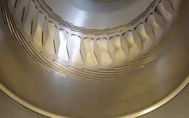
7 2. General Layout Drawings with the Method Statements and the Mode of Operation of the Pipe-Seal Systems LOCK (connected with the stainless steel sleeve behind) SERRATED LINE (in front of the pipe section) FLANGING The basic principle of the Pipe-Seal system consists in a defined rolled stainless steel sleeve, provided with an elastomer sealing, is spanned over a damaged spot. The sleeve is manufactured in a way that a permanent interlocking seal with the defected pipe wall is guaranteed. The compression of the sealing must be maintained during the whole service life. For the single installation, the area where rehabilitation is possible is located between the sealing lips. In order to bring the whole sealing without difficulty to the rehabilitation area, it is necessary to roll the stainless steel sleeve to a defined minus allowance compared to the diameter of the pipe to be rehabilitated. The locking mechanism mounted in the sleeve guarantees that the provided tension forces will be maintained during the whole service life. The locking mechanism (lock) of Pipe-Seal is able to lock the slightest movement or advance due to the special layout of the row of teeth. The advance is only possible in one direction. The locking pinion blocks any attempt of a backward movement. The individual components are described in the following sections. 3
 to the elastomer sealing behind. It is also the support of the statics in the pipe.")

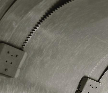
8 2.1 Pipe-Seal-Fix and Pipe-Seal-Flex Stainless Steel Sleeve The stainless steel sleeve is the carrier of the locking system consisting of the locking mechanism and the hold-down plate. Its function is to forward the initiated radial forces (produced by a packer balloon) to the elastomer sealing behind. It is also the support of the statics in the pipe. Row of Teeth The function of the row of teeth is to guide the locking pinions of the locking mechanism (lock). As soon as the sleeve has been tightened, the forces are transmitted via the row of teeth to prevent contracting or backward running of the stainless steel sleeve. Blocking forces must be transmitted from the row of teeth via the pinion to the sleeve. Stainless Steel Sleeve Slide Strip Slide Strip The slide strip serves as a counter bearing for the hold-down clamp and thus guarantees that the opposite locking pinions can freely move. Hence a conical expansion of the stainless steel sleeve is possible. It provides the locking mechanism guidance for the translatory motion and allows the pinion to be fixated in the row of teeth. Row of Teeth Hold-down Plate The hold-down plate is there to uniformly press the expanding sleeve sheet and fixes the unchanging space for the pinions. It is the basic unit for fixing the locking mechanism. Hold-down Plate 4

9 Locking Mechanism The locking mechanism consists of a pinion for running, guiding and power transmitting and of a spring-loaded locking pinion. The result of the arrangement of both interlocking pinions is that the sheet sleeve can only move in one direction and that the movement in the opposite direction is blocked. The pinion is fixed on a bearing shaft. It is adjusted in its position by means of a spring element. After the expansion of the sealing, the spring element loses its function. Transport Lock There are two different types of transport locks for the Pipe-Seal elements in order to prevent an unwanted expansion of the sleeve: adhesive strips or a plastic rivet (new). Locking Mechanism Flanging The flange is processed on one or both sides of the outer edge of the sleeve depending on the customer s request. The flanging guarantees a better hydraulic flow of the medium and a reduction of the resistance to flow. Stainless Steel Sleeve 5

10 2.2 Pipe-Seal-Flex Stainless Steel Sleeve The stainless steel sleeve is characterised by cut-out s in the middle area. Lamellar openings are worked in off-center. Due to the arrangement of the cut-out s and the lamellar openings, the normally rigid sleeve body can be formed; and so three-dimensional movements can also be realized as well: A tilting for curves in case of axial bending A buckling in case of misalignments A stretching, upsetting for the compensation in the curves A torsional movement in case of an overlapping of misalignment and axial bending Guide Plate Guide Plate The guide plate of stainless steel and serves as a cover of the cut-outs and the elongated slots and protects the elastomer sealing against infiltration. It is avoided that the sealing is pressed into the cut-outs and hence destroyed. 6


11 2.3 Elastomer Sealing The elastomer sealing for Pipe-Seal-Fix and Pipe-Seal-Flex is a cylindrical sealing with superimposed tapered sealing lips. This sealing is made with an excess length with an overlapping resp. a projecting end longer than the stainless steel sleeve. This projecting end is necessary for the sealing in case of an installation in series. In case of a single installation the projecting end is cut. Sealing Lips The elastomer sealing is provided with sealing lips in a defined spacing. When repairing a damaged pipe with a single sleeve installation, it is important to note that the damage is no bigger than the space between the pair of sealing lips. (The space between the pairs of lips is the actual width of rehabilitation being at the disposal.) Sealing Lips Rubber Projecting End Should it be necessary to place several seals together in order to cover the damage, the rubber end projecting over the stainless steel sleeve is the sealing. The rubber is only cut at the end sealing or in case of a single installation. Rubber Projecting End 7

 and / or an axial bending up to 8 including a flushing safety on both sides B) Preparing the Line The gravity line is to be prepared in a way that the camera-packer")
12 3. Overview of the Application of Pipe-Seal-Fix and Pipe-Seal-Flex Pipe-Seal-Fix Non-flanged: preferential for the installation in series Flanged on one side: appropriate for the single installation or as a last sleeve for the installation in series Flanged on both sides: most appropriate for single installation with flushing safety on both sides Pipe-Seal-Flex Non-flanged: for the installation in series in case of socket misalignments up to 1 (25 mm) and / or of an axial bending 8 in combination with Pipe-Seal-Fix Flanged on both sides: for single installation in case of socket misalignments up to 1 (25 mm) and / or an axial bending up to 8 including a flushing safety on both sides B) Preparing the Line The gravity line is to be prepared in a way that the camera-packer system including the sleeve can pass through without any restriction, i.e. The installation packer must be able to pass through without hindrance. Deposits and obstacles must be completely removed. The gravity line must be cleaned by flushing. Make sure all solids and other obstructions, such as discharge nozzles and root penetration, are also removed. It is recommended that work be performed with no sewer water running through the pipe. Space Requirement Packer Including Sleeve On request a Pipe-Seal-Flex flanged on one side can also be delivered. 3.1 Specification of the Application (installation begins here) A) Inspection / Deciding on the Type of Rehabilitation EPDM Rubber Stainless Steel Sleeve A thorough inspection when assessing the rehabilitation option and selecting the method of repair for the stainless steel sleeve. Possible options: - Single installation Pipe-Seal-Fix or Pipe-Seal-Flex - Installation in series with Pipe-Seal-Fix or in combination Pipe-Seal-Flex It must be guaranteed that at least one access via the inspection opening or the shaft / manhole. The size of the shaft should allow for packer, sleeve, and the camera together. The installation packers pass with their center line approximately.2 (0.5 cm) below the center line of the pipe. Example Calculation for the Space Requirement: Ø Pipe: 300 mm Ø Rolled Including EPDM Rubber: 263 mm (see technical data sheet) 300 mm mm = 37 mm above and below in total Above: 37 mm / 2 = 18.5 mm + 5 mm (axial bending pipe / packer) = 23.5 mm Below: 37 mm / 2 = 18.5 mm 5 mm (axial bending pipe / packer) = 13.5 mm A single sleeve with a Pipe-Seal-Flex sleeve has to be applied for the rehabilitation of socket misalignments bigger than.4 (1.0 cm)! 8
 Installation packer depending on the nominal diameter The installation packer, track expansion and wheel sets are")
13 C) Equipment Technology Material and Sleeve Preparation In order to work economically, the following materials should be available: Sewer CC/TV camera or robot system always adjusted to the nominal diameter of the reach (ideally the camera has a swivelling and zooming function) Installation packer depending on the nominal diameter The installation packer, track expansion and wheel sets are adapted to the respective nominal diameters of the reach Coupling rod for the connection to CC/TV camera and packer Compressed-air unit or compressor with an output of at least 72.5 PSI (5.0 bar) Compressed-air hose with a hose length of at least 3,937 (100 m) Quick release valve Milling robot for preparation work Sharp knife or scissors used in industry Talcum powder Current superglue Mineral Flex glue (root penetration, corrosion, armouring, reinforced concrete pipes) Equipment needed 9


 shorter than the sleeve.")
 shorter than the sleeve.")
14 D) Preparation of the Stainless Steel Collar F) Fixing the EPDM Rubber Before the installation the product has to be checked for possible damage during transportation. It is essential to cut and / or remove all the adhesive strips. On the Pipe-Seal-Flex the security tape is to be cut at the guide plate. E) Prepare EPDM rubber Fixing is necessary to prevent the rubber from being pushed off the sleeve or folded during the transport to the damaged spot. The superglue is to be evenly applied on maximum 4 points at the sides opposite to one another. The glue must not contact the area of the sliding and moving sheet metal parts and locking components. The EPDM rubber is powdered with talcum, so that it can be easily drawn over the sleeve. Friction between sleeve and rubber is reduced. The EPDM rubber has to be shortened afterwards, so that the rubber is on either side about ( cm) shorter than the sleeve. As to Pipe-Seal products flanged on one side, the rubber can be drawn more easily over the non-flanged side. Place the EPDM rubber in a centered position on the seal, in a way that the rubber end is on either side always about ( cm) shorter than the sleeve. It is absolutely necessary to use a sharp cutter knife or industrial scissors order to obtain a clean cut! In the case of a single installation the sealing effect is always between the two pairs of sealing lips and the rubber-projecting end is on principle cut. In the case of an installation in series, it is absolutely necessary to preserve the rubber-projecting end. G) Positioning of the Sleeve on the Installation Packer The Pipe-Seal sleeve must be positioned in such a way that the locking mechanism is always at the crown during a later expansion process. In the case a Pipe-Seal seal flanged on one side is used; the flanged side must principally be mounted in the opposite direction to the flow direction. Therefore it is important to watch the way that the sleeve is drawn on the packer. The Pipe-Seal sleeve has to be fixed onto the installation packer such that a continuous camera inspection of the installation procedure is possible at any time. A uniform overall picture is absolutely necessary! Preferably, the locking system should always expand at the same crown height and in the same direction. This is why it is absolutely necessary that the lock on the installation packer is skid-proof and positioned with 7.25 PSI (0.5 bar) between 12 o clock Position 11 or 1 o clock. Important criteria for the exact positioning of the lock: Improvement for passing through Free moving space The installation process can be better documented Prevention of obstructions in the outflow 10
 is built-up.")
. The flanging is about.12 -.")
15 3.2 Single Installation Installation of a Flanged Sleeve The Pipe-Seal sleeve flanged on one side must always be in installed with the flanging in the opposite direction to the flow direction. The sleeve with the EPDM rubber should be adjusted in the center of the damage. Then a pressure of about PSI ( bar) is built-up. Flanging in opposite direction to the flow A correction of the position is still possible now! After having fixed the exact position of the Pipe-Seal sleeve, the final installation pressure can be built-up (annex). The flanging is about (3-5 mm) depending on the nominal width of the sleeve and hence covers the EPDM rubber. As soon as the installation procedure has been finished, a control by means of a CC/TV camera is required. Thus it can be checked whether a retightening of the sleeve is necessary. Reflection Please watch that the flanging does not butt against the pipe wall! Note to the Reflection In a vitrified clay pipe or in case of an installation in series in a steel pipe, reflections may occur after the installation procedure due to the light of the CC/TV camera. This can be avoided by changing the camera perspective. 11
 (space between the sealing lips), several non-flanged sleeves must be set: Basically, the installation in series is carried out from the low point (direction opposite to flow).")
16 3.3 Installation in Series When the damage is bigger than approximately 11.8 (30 cm) (space between the sealing lips), several non-flanged sleeves must be set: Basically, the installation in series is carried out from the low point (direction opposite to flow). In case of an installation in series it is absolutely important that the first and the last sealing lip is applied at least 5.9 (15 cm) outside the damaged spot. It is imperative to use the rubber projecting end! Distance sealing lip to sleeve The last sleeve (flanged on one side) is installed without a rubberprojecting end in the opposite direction of the flow direction (see description single installation). Like in the single installation, one must care for the installation pressures in the installation in series as well. During the installation in series, small misalignments result from the sleeve overlapping (but they are not an obstacle to the outflow). Therefore it makes sense that the installation takes place in the opposite direction of the flow direction. When passing through the Pipe-Seal sleeve, it is important that folding does not occur at the rubber projecting end. Should this happen, you must drive back completely, so that the projecting end can again straighten and you repeat the procedure. 12
17 3.3.1 Installation in Series Step-By-Step D) Last Sleeve A) Preparing the Pipe-Seal sleeves Find out how many sleeves are necessary (e.g. three sleeves for a pipe length of 40 (1 m) two non-flanged, one flanged on one side). Sheathe the Pipe-Seal sleeve with EPDM rubber and fix it (s. single installation). Do not cut the projecting end of the rubber of the non-flanged sleeves! The last sleeve is flanged on one side. Here, the projecting end of the rubber must be cut. B) Positioning The last sleeve with the flanging on one side is installed as described under B. Pay attention to that at the last sleeve the last sealing lip is positioned at least 5.9 (15 cm) outside the damage. Caution! In the case of overlapping of the sleeves, the sleeve must in no way be placed on the locking mechanism. The bearing surface of lock and sleeve end has enough space to guarantee an overlapping. The last sleeve should preferably be flanged on one side. The projecting end of the rubber must be cut. The flanging shows in the opposite direction to the flow! Position the first sleeve on the packer in such a way that the sleeve is skid-proof (approximately 7.23 PIS [0.5 bar]) and supervision with a CC/TV camera is possible. The first sleeve (contrary to the flow direction) must be positioned with the first sealing lip at least 5.9 (15 cm) outside the damaged spot. Expand the sleeve with the installation pressures (annex). Please consider that in case of longitudinal cracks, rehabilitation must take place from socket to socket, as longitudinal cracks usually run over the whole pipe length. As to the rubber overlapping, be careful that folding does not occur, because then the optimal sealing effect of the sleeve can no longer be guaranteed. C) Overlapping of the Sleeves Pass with the second sleeve through the first sleeve to about 1 / 5 (0.5 cm) behind the second lock. Thus about 3 / 5 (1.5 cm) is available for the overlapping of the sleeves. It is important that folding does not occur at the rubber projecting end of the first sleeve and that overlapping of the second sleeve is not placed over the lock! Now expand the second sleeve. Position the installation packer anew on the overlapping sleeves and provide the appropriate installation pressure. Due to the overlaps the rubber is sealed inside the overlapping and sealing lips inside the projecting end of the rubber! Should you need any more sleeves (depending on the length of damage), the procedure will be repeated. 13
18 4. Misalignments and Axial Bending with Pipe-Seal-Flex Socket misalignments which are bigger than.4 (1.0 cm) can be best rehabilitated with a Pipe-Seal-Flex sleeve. This sleeve is flexible, it is conically expanding and it can be ideally adjusted to the pipe appropriate for misalignments to 1 (2.5 cm) and / or an axial bending of 5º. The installation of the sleeve must be carried out the following way: 1. Prepare the Sleeve Pour talcum powder on the EDPM rubber. Carefully slide the EDPM rubber to the first transport lock. Cut no more than 50% of the safety tape. Draw EPDM rubber to the second transport lock and repeat the procedure until the last one just as described before. Afix the EPDM rubber with superglue at four points opposite to one another. The installation packer must be positioned with approx PSI (0.5 bar) in such a way that CC/TV supervision is possible. 3. Control With a CC/TV camera, it must now be verified once more, whether the Pipe-Seal-Flex entirely butts against both sides of the pipe wall. If so, the installation procedure is finished. If not, repeat the last two steps. Note Should an installation in series, usually done with Pipe-Seal-Fix, require rehabilitation with Pipe-Seal-Flex, the products can be combined without difficulty. Please hold out for the case when you need a flanged or a non-flanged sleeve! 2. Installation Transport Pipe-Seal-Flex to the damage and find out the exact location. The sleeve should be positioned in the center of the damage. Expand the installation packer with approx PSI (1-1.5 bar). Completely relieve pressure from the packer and do not change the position of the packer. Restart expansion of the packer to PSI (2-2.5 bar). Then, completely relieve pressure from the packer. Now, position the installation packer in the center of the rear lock and apply the appropriate installation pressures (acc. to list). Then again completely relieve the packer. Move the packer to the front lock and repeat the procedure as described above. 14

19 5. Removal of Placed Pipe-Seal-Fix and Pipe-Seal-Flex Sleeves Blind inlets or misfit dislocation are often closed with a stainless steel Pipe-Seal sleeve. Should these sleeves be removed from the blind inlets and the misfit dislocation, the locking mechanism can be destroyed. For this purpose a milling robot is equipped with a common flex disc for metals. In order to remove the sleeve, it is necessary to cut each lock, so that the sleeve with the EPDM rubber can contract again a bit due to the surface tension. The sleeve has loosened in the pipe and can be removed without effort. 15
20 6. Special Applications with Pipe-Seal 6.1 Pipe-Seal-Fix in Tight Pipe Systems 6.2 Root Penetration The sealing of the Pipe-Seal-Fix sleeve is provided by the EPDM sealing rubber on a compression basis. Thus excellent sealing results are obtained. When Pipe-Seal-Fix is used in tight pipe systems there is the risk that in the space between the pairs of sealing lips and the old pipe an overpressure is built-up. This effect arises especially in pipe systems with a smooth pipe wall and a tight pipe structure (plastic pipes, GFRP pipes and glazed vitrified clay pipes). This enclosed air cushion may have an influence on the flushing safety. The Pipe-Seal- Fix sleeve might shift when a high-pressure jet hits on the sleeve edge or the high-pressure jet might penetrate between the sleeve and the old pipe and then further build-up the already existing overpressure. Tests have shown that the overpressure slowly decreases by diffusion. In case of pre-existing root penetration, a special procedure is required to prevent future root penetration after the rehabilitation procedure is completed. Since roots can continue to grow along the sleeve, they well seek a way into the pipe through the sealing lip. By following the special procedure below, this can help reduce the chance of this occurring. Remove all penetrating roots before rehabilitation. Apply a high alkaline mineral flex glue to the EPDM rubber sealing between the interior sealing lips to the sealing lip height. It is absolutely necessary to use a product with adhesive properties so that you do not lose the applied material in the reach. The flex properties provide in addition that the applied material can be overstretched with the EPD rubber and does not tear. 16
21 Annex Survey : Contact Pressures Type of Pipe Damage Nominal Diameter Contact Pressure 7.5 (188 mm) PSI ( Bar) Longitudinal cracks 7.9 (200 mm) PSI ( Bar) PVC, concrete, asbestos cement and vitrified clay pipe ( mm) 7.5 (188 mm) PSI ( Bar) PSI ( Bar) Transverse cracks, leaky sockets 7.9 (200 mm) PSI ( Bar) ( mm) PSI ( Bar) 7.5 (188 mm) PSI ( Bar) GFRP (PE, PP), reinforced concrete and grey cast iron pipes All 7.9 (200 mm) PSI ( Bar) ( mm) PSI ( Bar) The listed contact pressures are standard values. Important: Watch dwell time and setting time of the rubber! 17

22 720 / 454 / Pipe-Robo-Tec USA 9155 Wallisville Road Houston, TX info@piperobotecusa.com 11/15 USA
Catalogue Easy inside
 Catal ogue 2.2010 The complete product range Mini Middle Page 4: Unifix Mini: The small, light and quick repair solution for sealing holes, fractures and porous areas in water-bearing pipes. Suitable for
Quick-Lock User Manual
 DIBt certification No. Z-42.3-374 Quick-Lock User Manual 5th revision, version 03/2015 [english us] Sold by: Kanaltechnik GmbH Dear Quick-Lock user, Preface This manual shows you how to use our Quick-Lock
PSI CASING END SEALS FOR CASING PIPE CLOSURE FOR PROTECTION AGAINST MOISTURE AND DIRT ALSO FOR RETROFITTING INDIVIDUAL CUSTOMIZED SOLUTIONS
 PSI CASING END SEALS FOR CASING PIPE CLOSURE FOR PROTECTION AGAINST MOISTURE AND DIRT ALSO FOR RETROFITTING INDIVIDUAL CUSTOMIZED SOLUTIONS WWW.PSI-PRODUCTS.COM 111 PSI Casing End Seals Pipes carrying
Length 200 mm (knife included) 310 mm (knife included)
 310 mm (knife included)") Hydraulic root cutter The best solution for drains that are blocked by roots, hard grease, compacted sand or soil. The Rioned root cutters are powerful, reliable and easy to use. They consist of a central
Hydraulic root cutter The best solution for drains that are blocked by roots, hard grease, compacted sand or soil. The Rioned root cutters are powerful, reliable and easy to use. They consist of a central
PSI Link-Seal Modular Seals
 01 General Information Technical Data Selection Guide Order Submittal Sheet Installation Instruction PSI Link-Seal Modular Seals Pipeline Accessories 5 Link-Seal Modular Seals General Information Application
Operating and maintenance instructions VAG RETO-STOP Non-Return Valve
 Operating and maintenance instructions VAG RETO-STOP Non-Return Valve KAT 1544-B Edition2 02-09 Content 1.General 1.1 Safety 1.2 Proper use 2.Transport and storage 2.1 Transport 2.2 Storage, packaging
CHAPTER 12: OPERATIONS & MAINTENANCE
 CHAPTER 12: OPERATIONS & MAINTENANCE Figure 12-1: A combination sewer cleaning truck is used to hydro-flush and vacuum sewer lines. The nozzles and tools used with similar trucks have advanced dramatically
Flexible Couplings. Large Diameter Coupling. Global leaders in flexible couplings, drainage & plumbing systems. Benefits
 Flexible Couplings Large Diameter Coupling Flexseal can provide Large Diameter Couplings that are manufactured to order, thereby meeting the specific contractor and site requirements. Large Diameter Couplings
Psi casing spacers insulators For PiPE-iN-PiPE systems
 PSI Casing Spacers Insulators for Pipe-in-Pipe Systems www.psi-products.com 69 PSI Casing Spacers General information Polypropylen casing spacers are universally applicable in the installation of pipelines
INDUSTRIAL VACUUM SYSTEMS MADE AND MANUFACTURED IN GERMANY RANGE OF ACCESSORIES COMPETENCE CENTRE INDUSTRIAL VACUUMING. Valid from
 INDUSTRIAL VACUUM SYSTEMS MADE AND MANUFACTURED IN GERMANY Valid from 01.01.2019 COMPETENCE CENTRE INDUSTRIAL VACUUMING 2 3 DEAR CUSTOMER, This catalogue provides you with an essential selection of the
BUTTERFLY VALVE WITH WELDED ENDS INSTALLATION AND MAINTENANCE MANUAL
 BUTTERFLY VALVE 31300 SERIES INSTRUCTIONS FOR INSTALLATION, USE AND MAINTENANCE 1. Overview Read these instructions carefully before starting the valve installation and start-up work. Safe keep the instructions
Installation handbook
 Installation handbook INDEX SAFETY INSTRUCTIONS 4 5 GENERAL INSTALLATION DETAILS 6 10 Installation Information 6 Planning 7 10 Tools 10 PIPE INSTALLATION 11 16 Working with PVC 11 12 Important Pipe Installation
General information on radial seals
 170 General information on radial seals Radial seals is the common name for shaft seals, which seal against a rotating shaft using an elastic and resilient lip of rubber or PTFE. The lip in turn is either
PSI Compakt-Seals. Pipeline Accessories. Compakt-Standard Compakt-Special Compakt-Varia. General Information. Selection Guide. Order Submittal Sheet
 2 General Information Selection Guide Order Submittal Sheet Installation Instruction PSI Compakt-Seals Compakt-Standard Compakt-Special Compakt-Varia Pipeline Accessories 21 General Information The Sealing
PSI Plastic Insulators System
 Pipeline Accessories PSI Plastic Insulators System General Information Technical Data Selection Guide 1 PSI Plastic Insulators System Material Test Certificate PSI Plastic Insulators System General Information
2.- HANDLING OF VALVES BEFORE ASSEMBLY 3.- FITTING THE VALVE TO THE REST OF THE ASSEMBLY 5.- PERIODICAL INSPECTION OF THE VALVE AND MAINTENANCE
 Page 1 of 16 CONTENTS 1.- INTRODUCTION 2.- HANDLING OF VALVES BEFORE ASSEMBLY 3.- FITTING THE VALVE TO THE REST OF THE ASSEMBLY 4.- OPERATION OF A BALL VALVE 5.- PERIODICAL INSPECTION OF THE VALVE AND
3. BEARING ARRANGEMENT DESIGN
 3. BEARING ARRANGEMENT DESIGN 3.1 GENERAL PRINCIPLES OF ROLLING BEARING ARRANGEMENT DESIGN Rotating shaft or another component arranged in rolling bearings is guided by them in radial as well as in axial
For advanced drive technology CLAMPEX. Shaft-Hub-Connection. KTR Precision Joints CLAMPEX
 technology CLAMPEX Shaft-Hub-Connection CLAMPEX KTR Precision Joints 07 technology Table of contents Page Brief information 09 Selection and calculation -5 CLAMPEX -Selection Shaft diameter = d 0 10 0
Installation and Operating Instructions for ROBA -ES couplings Type 940. _. _ Sizes 14-48
 Table of contents: Please read and observe this Operating Instruction carefully. A possible malfunction or failure of the clutch and damage may be caused by not observing it. Page 1: - Table of contents
PSI CASING SPACERS TYPE DSI
 PSI CASING SPACERS TYPE DSI INSULATORS FOR PIPE-IN-PIPE SYSTEMS MEETS ALL REQUIREMENTS OF THE CATHODIC PIPE PROTECTION WIDE RANGE OF SKID HEIGHTS MAKES THE CENTERING EASY EASY PENETRATION OF CARRIER PIPE
General information Gate valves
 General information Gate valves In 1957, Hawle invented the resilient-seated gate valve with multiple O-ring sealing of the valve spindle and had it patented. Today, this type of gate valve is the standard
Butterfly valves. Introduction. Made of ductile cast iron
 Made of ductile cast iron Introduction The portfolio of valves supplied by Keulahütte GmbH in Krauschwitz is rounded off by butterfly valves and check valves, which have been designed according to international
MUELLER ECCENTRIC PLUG VALVE
 MUELLER INSTALLATION, OPERATING and MAINTENANCE INSTRUCTIONS 1 MUELLER System Design The life of the valve is dependent on its application, frequency of use and freedom from misuse. The properties of the
Brake System H TX, H2.0TXS [B475]; H TX [B466] Safety Precautions Maintenance and Repair
![Brake System H TX, H2.0TXS [B475]; H TX [B466] Safety Precautions Maintenance and Repair](/thumbs/86/93834005.jpg "Brake System H TX, H2.0TXS [B475]; H TX [B466] Safety Precautions Maintenance and Repair") HMM180001 Brake System H1.5-1.8TX, H2.0TXS [B475]; H2.5-3.5TX [B466] Safety Precautions Maintenance and Repair When lifting parts or assemblies, make sure all slings, chains, or cables are correctly fastened,
HMM180001 Brake System H1.5-1.8TX, H2.0TXS [B475]; H2.5-3.5TX [B466] Safety Precautions Maintenance and Repair When lifting parts or assemblies, make sure all slings, chains, or cables are correctly fastened,
JUNG PUMPEN COMPLI 100 MC SEWAGE LIFTING STATIONS
 APPLICATION The sewage lifting stations compli 100, compli 500 and compli 1000 with MultiCut cutting system are uses especially for disposal in special objects, such as weekend cottages, houseboats, toilets
J e t t i n g n o z z l e s
 J e t t i n g n o z z l e s Setting the standard Overview jetting nozzles Jetting nozzles For each type of high pressure machine For drains up to 600 mm Highest efficiency For all kind of blockages Radial
Installation Manual. For inner sealing sleeves in accessible pipelines, nominal diameters DN inch and Liner End Seal DN 8 inch
 Installation Manual For inner sealing sleeves in accessible pipelines, nominal diameters DN 32 95 inch and Liner End Seal DN 8 inch General information Preparing the installation positions Installation
GL Ludemann Y-Strainers
 GL Ludemann Y-Strainers Installation, Operation and Maintenance Manual English Issue 1-03/2014 - Page 1/7 GENERAL These instructions are for installing, operation and maintenance of Y-strainers fabricated
h Technical Product Data CC Pressure Pipe Systems
 h Technical Product Data CC Pressure Pipe Systems Amiblu Holding GmbH All rights reserved. Publication: 09/2018 This version replaces all previous versions. For all current data please visit our website
V-Rings around the clock... around the clock...
 Description V-rings are rotary seals that can perform numerous jobs in their function of sealing rotating shafts: sealing against the penetration of dirt, dust, water or watery pollutants, combination
Pipeline Accessories. Rubber Steel gasket Type RSG Type RSG-V Type RFG 4 pipes
 Pipeline Accessories Rubber Steel gasket Type RSG Type RSG-V Type RFG 4 pipes Flange Gaskets Type RSG 4 pipes Reg.Nr. NG-5113CQ0574 Trinkwasser KTW/W270 Product Information RSG 4 pipes Rubber-Steel-Flange-Gasket
CPF INSTALLATION, OPERATION, AND MAINTENANCE MANUAL FLANGED SERIES CHECK VALVE *
 CPF INSTALLATION, OPERATION, AND MAINTENANCE MANUAL FLANGED SERIES CHECK VALVE * Elasto-Valve s CPF Series is a flanged, bolt-on duckbill Check Valve manufactured with top quality elastomeric materials.
FKB INDÚSTRIA DE EQUIPAMENTOS LTDA. KNIFE GATE VALVE VGU-05 (Rev. 08/2015)
") General Description The FKB Knife-gate valves model VGU-05 brings cost-effective solution to block the flow of abrasive fluids. These are strong equipments to be installed between flanges, which has Wafer
General Description The FKB Knife-gate valves model VGU-05 brings cost-effective solution to block the flow of abrasive fluids. These are strong equipments to be installed between flanges, which has Wafer
TIDALFLUX 2300 F Quick Start
 Quick Start Electromagnetic flow sensor for partially filled pipes The documentation is only complete when used in combination with the relevant documentation for the signal converter. KROHNE CONTENTS
FLUID POWER FLUID POWER EQUIPMENT TUTORIAL PIPE WORK. This work covers part of outcome 2 of the Edexcel standard module:
 FLUID POWER FLUID POWER EQUIPMENT TUTORIAL PIPE WORK This work covers part of outcome 2 of the Edexcel standard module: UNIT 21746P APPLIED PNEUMATICS AND HYDRAULICS The material needed for outcome 2 is
Sibre All Steel Couplings
 Overview Coupling is device to transmit torque from driving side to driven side and also has function of compensation of axial,radial,angular misalignment which generated by manufacturing, installation
Flexible Couplings & Saddles
 Revised 6/01 Flexible Sewer couplings are the result of many years of experience with sewer pipe connections. Today's couplings are made of specially formulated elastomeric PVC with high tear and shear
JUNG PUMPEN compli 100 MC Sewage lifting stations
 Application The sewage lifting stations compli 100, compli 500 and compli 1000 with MultiCut cutting system are uses especially for disposal in special objects, such as weekend cottages, houseboats, toilets
5. STRAUB-FLEX / STRAUB-REP
 5. STRAUB-FLEX / 5.1 STRAUB-FLEX For gas and water supply, sewage treatment, industrial plants, power plants and shipbuilding: STRAUB- FLEX is the optimal pipe joint. Suitable for suction or pressure lines,
Our products for water transmission Double-eccentric butterfly valves Air valves Non-return valves Connection systems
 Water transmission Lengths of over 100 kilometres and nominal widths of over DN 100 are not unusual for large scale water transmission systems. Often they are installed as parallel pipelines. They ensure
Shaft-Hub-Connections
 Stand: 14.01.2010 Shaft-Hub-Connections Shrink Discs Cone Clamping Elements Star Discs 36 Edition 2012/2013 RINGSPANN Eingetragenes Warenzeichen der RINGSPANN GmbH, Bad Homburg Table of Contents Introduction
JUNG PUMPEN MULTICUT SEWAGE PUMPS
 APPLICATION Centrifugal submersible sewage pumps fitted with the MultiCut cutting system are used as stationary appliances for backpressure protection of detached houses. They are suitable for pumping
Insulating joint IK. Insulating joint IK. RMA Kehl GmbH & Co. KG Oststrasse 17 D Kehl / Germany
 Insulating joint IK RMA Kehl GmbH & Co. KG Oststrasse 17 D-77694 Kehl / Germany info@rma-kehl.de www.rma-armaturen.de 1 Monoblock insulating joints are boltless, rigid pipeline components, factory-welded
AUTOMATIC AIR VALVES For potable water
 AUTOMATIC AIR VALVES For potable water Page N Air release valve Page N Air release valve avent Page N Air release valve DN 0 / DN 0, DN 150 / DN 00 Page N /1 Page N5 Combined air release valve Page N 5/1
disc brake axle with WABCO calipers
 1 2 disc brake axle with WABCO calipers 3 4 disc brake axle with WABCO calipers 5 6 disc brake axle with WABCO calipers IMT axles are supplied as non-cambered and are within the limits of a 2 minute negative
For advanced drive technology CLAMPEX. Shaft-hub-connection. KTR Precision joints CLAMPEX
 technology CLAMPEX Shaft-hub-connection CLAMPEX KTR Precision joints 227 technology Table of contents Page Brief information 228 Selection and calculation 25-255 CLAMPEX -Selection Shaft diameter = d 0
NYL Resilient Seated Butterfly Valves Operation and Maintenance Instructions
 COMMERCIAL Bray Controls Commercial Division 13788 West Road, Suite 200A Houston, Texas 77041 BCDSales@Bray.com Phone: 1-888-412-2729 Fax: 1-888-412-2720 www.braycommercialdivision.com NYL Resilient Seated
Water Supply and Sewerage Approved Products Manual - February 2006
 Water Supply and Sewerage Approved Products Manual - February 2006 Gravity Sewerage Products Vitrified Clay Pipeline System Section SGPS 02 Last updated Jan 2007 CONTENTS A SGPS 02-S1 PIPES TO EN 295 A
D-04/G-04 Maintenance
 D-04/G-04 Maintenance NOTE: The numbers in parentheses are the Ref. Nos. on the illustrations in the Parts Manual. Daily Check the oil level and the condition of the oil. The oil level should be 1/4 in.
WARNING Carefully Read These Instructions Before Use
 DO NOT RETURN THIS SPRAYER TO STORE Call: 1-800-950-4458 Backpack Sprayer Use and Care Manual Manufactured for Northern Tool + Equipment Co., Inc. WARNING Carefully Read These Instructions Before Use Model
Swivel Joint Heads (Basic Unit)
") Swivel Joint Heads (Basic Unit) Design Configuration Weld edge preparation according to DIN 2559 or ANSI B16.25 Grease nipple/ ball Lifetime greasing Grease nipple only on request Stator Rotor Internal
Swivel Joint Heads (Basic Unit) Design Configuration Weld edge preparation according to DIN 2559 or ANSI B16.25 Grease nipple/ ball Lifetime greasing Grease nipple only on request Stator Rotor Internal
ONYX VALVE CO MODEL DAO-ADA Installation & Maintenance
 ONYX VALVE CO MODEL DAO-ADA Installation & Maintenance OPERATION: (4-2010) The Onyx DAO-ADA pinch valve is an open frame valve without housing enclosure and fails last position on loss of air. This actuator
ONYX VALVE CO MODEL DAO-PFC Installation & Maintenance
 ONYX VALVE CO MODEL DAO-PFC Installation & Maintenance OPERATION: (4-2010) The Onyx DAO-PFC pinch valve is an open frame valve without housing enclosure and fails closed on loss of air. The actuator drives
Selection Tool. on the Internet at in the section MÄDLER -Tools. Other sizes and designs on request. Connecting Shafts Page 766
 Couplings Overview Friction Clutches Friction Clutches Type B Axial Arrangement Friction Clutches Type C Transversal Flexibility Sliding Hubs with Torsionally-Flexible Coupling Multi-Disk Friction Clutches
Hawle-FIT Fittings for PE pipes Page K 2/1 Assembly and dismantling instructions Page K 2/2
 FITTINGS Page K 2 Hawle-FIT Fittings for P pipes Page K 2/1 Assembly and dismantling instructions Page K 2/2 Page K 3 Page K 4 ISO pipe fitting Fittings for P pipes Page K 3/1 ISO pipe fitting assembly
ERHARD is a company of. Datasheet ERHARD ABS Premium service valve
 ERHARD is a company of Datasheet ERHARD ABS Premium service valve ERHARD ABS Premium service valve The innovative tapping systems With the new it has been possible to reduce the number of required models
PROJ. NO SECTION HYDRONIC PUMPS
 SECTION 23 21 23 HYDRONIC PUMPS PART 1 - GENERAL 1.1 RELATED DOCUMENTS A. Drawings and general provisions of the Contract, including General and Supplementary Conditions and Division 01 Specification Sections,
PIPE PLUGS & PACKERS
 PIPE PLUGS & PACKERS CONTENTS Small dimension plugs 1.1. Plugs of smaller dimensions PLUGY Z and PLUGSY S 4 1.2. Long plugs PLUGY DC 6 1.3. Gas plugs PLUGY G and PLUGSY gm 8 1.0. PNEUMATIC PIPE PLUGS Larger
FLEXWELL Safety Pipe. Pipe systems for installations Technical details
 Pipe systems for installations Technical details Notes 26.01.2015 T page 2 Contents 4.0 4.0 Contents 4.1 System description 4.100 System description FLEXWELL Safety Pipe 4.105 System description FLEXWELL
FLANGE. Flanges used for
 FLANGE FLANGE Flanges with rating class designations 150, 300, 400, 600, 900, 1500, and 2500 in sizes NPS 1 2 through NPS 24 ASME B16.5: Pipe Flanges and Flanged Fittings (NPS 24 ) ASME B16.47: NPS 26
BETTIS SERVICE INSTRUCTIONS DISASSEMBLY AND REASSEMBLY FOR CB-SR-S SEISMIC SPRING RETURN SERIES PNEUMATIC ACTUATORS
 BETTIS SERVICE INSTRUCTIONS DISASSEMBLY AND REASSEMBLY FOR CB-SR-S SEISMIC SPRING RETURN SERIES PNEUMATIC ACTUATORS PART NUMBER: 102264 REVISION: "C" DATE: November 2000 Page 1 of 11 1.0 INTRODUCTION 1.1
M Installation Guide. PRECISION Manifold Series. Introduction. A. Assemble Manifold Components
 Page 1 Introduction The M-8200 Precision Manifolds are designed for use in Hydronic radiant panel heating and cooling applications. They are available in various sizes, configurations, and options with
PSI HEAT SHRINK PRODUCTS -
 PSI HEAT SHRINK PRODUCTS - CORROSION PROTECTION AND SEALING (SYSTEM CANUSA) COMPATIBILITY WITH ALL PIPE COATINGS IMPACT AND ABRASION-RESISTANT MATERIAL EASY INSTALLATION BY SHRINK ON WWW.PSI-PRODUCTS.COM
M-8100EP. Installation Guide ENGINEERED PLASTIC MANIFOLD SERIES. Introduction. A. Assemble Manifold Components
 Introduction The Pro Manifolds with Integrated adaptor are designed for use in Hydronic radiant panel heating and cooling applications. They are available in various sizes, configurations, and options
Swivel Joints Rotary Unions
 Maschinenbau GmbH & Co. KG Swivel Joints Rotary Unions since 1970 Knowledge and experience General Information We about us Klaas Maschinenbau GmbH & Co. KG was founded in the year 1970 and is an independent
GBV-G Balancing Valves
 Ductile Iron ASTM A6, Grade 6-4-2 The Series GBV is a multi-turn, Y-style globe valve designed for accurate determination and control of fluid flow to circuits requiring precise balancing. Max. Working
Maintenance Instructions
 General Note These instructions contain information common to more than one model of Bevel Gear Drive. To simplify reading, similar models have been grouped as follows: GROUP 1 Models 11, 0, 1,, (illustrated),,
EISELE IS QUALITY MADE IN GERMANY AVAILABLE ON STOCK IN GRAND RAPIDS, MI
 2 Quality solutions - Made by EISELE EISELE IS QUALITY MADE IN GERMANY AVAILABLE ON STOCK IN GRAND RAPIDS, MI Over 30 patents, more than 8,000 standard articles, and 2,000 customized solutions impressively
UNIJOINT is a company of. UNIJOINT Eurocoup Flange Adaptors & Couplings
 UNIJOINT is a company of UNIJOINT Eurocoup Flange Adaptors & Couplings UNIJOINT For Challenging Pipe Connections UNIJOINT, established in 1992 in the Netherlands, is a company with a vast experience in
FUNDAMENTAL SAFETY OVERVIEW VOLUME 2: DESIGN AND SAFETY CHAPTER E: THE REACTOR COOLANT SYSTEM AND RELATED SYSTEMS
 PAGE : 1 / 13 4. PRESSURISER 4.1. DESCRIPTION The pressuriser (PZR) is a pressurised vessel forming part of the reactor coolant pressure boundary (CPP) [RCPB]. It comprises a vertical cylindrical shell,
DESIGN OF MACHINE ELEMENTS UNIVERSITY QUESTION BANK WITH ANSWERS. Unit 1 STEADY STRESSES AND VARIABLE STRESSES IN MACHINE MEMBERS
 DESIGN OF MACHINE ELEMENTS UNIVERSITY QUESTION BANK WITH ANSWERS Unit 1 STEADY STRESSES AND VARIABLE STRESSES IN MACHINE MEMBERS 1.Define factor of safety. Factor of safety (FOS) is defined as the ratio
ELEVATOR BELT & BELT SPLICE INSTALLATION GUIDE
 ELEVATOR BELT & BELT SPLICE INSTALLATION GUIDE Textile & Steel Web Belting (Revision 4) www.go4b.com/usa 2 TABLE OF CONTENTS Textile Elevator Belt Installation - General Information... Page 3 - Tools &
REPAMAX. Versatile Stainless Steel Coupling. Versatile Stainless Steel. By Krausz Wide-Range Couplings. Joins as a coupling. Repairs as a clamp.
 JOIN REPAIR RESTRAIN REPAMAX Versatile Stainless Steel By Krausz Wide-Range Couplings Joins as a coupling. Repairs as a clamp. Versatile Stainless Steel Coupling REPAMAX Product Information Versatile Stainless
Calculation on a valve housing flange
 Calculation on a valve housing flange numerical FEM analysis versus analytical calculation according to DIN EN 12516-2 Dipl.-Ing. Gerd Lannewehr Peter Thomsen Lannewehr + Thomsen GmbH & Co.KG 28211 Bremen,
OPERATING INSTRUCTIONS
 Emergency Cord Switch Type PRS Device identification No.: 91.054 033.001, /.101 and /.201 OPERATING INSTRUCTIONS 2 CE Sign and Conformity The device meets the requirements of the valid European and national
Compact Modules. with ball screw drive and toothed belt drive R310EN 2602 ( ) The Drive & Control Company
 The Drive & Control Company") with ball screw drive and toothed belt drive R310EN 2602 (2007.02) The Drive & Control Company Bosch Rexroth AG Linear Motion and Assembly Technologies Ball Rail Systems Roller Rail Systems Linear Bushings
with ball screw drive and toothed belt drive R310EN 2602 (2007.02) The Drive & Control Company Bosch Rexroth AG Linear Motion and Assembly Technologies Ball Rail Systems Roller Rail Systems Linear Bushings
Dr. TRETTER AG. Tolerance Rings. safe cost-effective fast assembly
 Dr. TRETTER AG Tolerance Rings safe cost-effective fast assembly Tolerance Rings are corrugated metal strips manufactured of high quality spring steel. Tolerance Rings are a fastening device between two
: 1250 gpm in the deck mode : 800 gpm while operating in the ground base - Dual Inlet : 1000 gpm while operating in the ground base - Single Inlet
 APOLLO HI-RISER MONITOR STYLE 3433/3431 INSTALLATION, OPERATING, AND MAINTENANCE INSTRUCTIONS The following is intended to provide the basic instructions for installation, operation and maintenance of
FURROW PRESSES VARIOPACK FIXPACK FLEXPACK
 FURROW PRESSES VARIOPACK FIXPACK FLEXPACK 2 Ploughing with furrow presses? Ploughing loosens and crumbles the soil, and at the same time, increases its pore volume. This introduces air and warmth into
MPI Remote Operated Net Cleaning Systems MPI R.O.N.C Users Manual
 MPI R.O.N.C Users Manual Maintenance and spare parts for MPI remote operated cleaning units R.O.N.C., 5, 7, and 9 - Ver. B. Introduction Dear customer, Congratulations on Purchasing your MPI remote operated
Operating Instructions. Pneumatic Control Valve Low Temperature. Type Series GS3
 Operating Instructions Pneumatic Control Valve Low Temperature Type 8026 Series GS3 With: Digital Positioner Type 8048 Electro-pneumatic Positioner Type 8047 Pneumatic Positioner Type 8047 Version: 03/2006
Personal Protection Equipment (PPE) Safety Glasses Protect eyes Welding Mask Protect eyes and face
 Safety Glasses Protect eyes Welding Mask Protect eyes and face") Table of Contents: Title Page... 1 Introduction... 3 Before Construction... 3 Equipment Needed... 3 Drawings... 4 Construction... 5 1. Cut Sheet Drawings... 5 2. Base... 5 3. Combustion Chamber... 12 4.
Table of Contents: Title Page... 1 Introduction... 3 Before Construction... 3 Equipment Needed... 3 Drawings... 4 Construction... 5 1. Cut Sheet Drawings... 5 2. Base... 5 3. Combustion Chamber... 12 4.
Manifold Isolation Valves
 300 N. Opdyke Rd. Introduction The Stainless Manifolds are designed for use in Hydronic radiant panel heating and cooling applications. They are available in various sizes, configurations, and options
series BUTTERFLY VALVE DOUBLE ECCENTRIC FLANGED FAF 3800 PRODUCTION STANDARDS DN100 DN2000 PN Design EN 593 EN ISO Flanged
 PRODUCTION STANDARDS DN100 DN2000 PN 10-16-25 Design EN 593 Connection End Connection EN 1092-2 ISO 7005-2 - Flanged EN 558 Series 14 DIN 3202 F4 Marking EN 19 Tests EN 12266-1 Corrosion Protection Electrostatic
FIG Gruvlok Flanges
 Gruvlok Flanges The Gruvlok Fig. 7012 Flange allows direct connection of Class 125 or Class 150 flanged components to a grooved piping system. The two interlocking halves of the 2" thru 12" sizes of the
PRECISMECA - MONTAN Gesellschaft für Fördertechnik mbh. Documentation Operating Instructions. Rollers
 PRECISMECA - Gesellschaft für Fördertechnik mbh Documentation Operating Instructions Rollers Operating Instructions Index No.: T311-00 Page: 1 of 1 Section Document No. Pages Preface Safety Technical data
HURST COMP/PLUS SHIFTER 2015 Ford Mustang (Getrag MT82 six-speed manual transmission) Catalog # by Hurst Performance
 Catalog # by Hurst Performance") FORM 159 0205 07/15 HURST COMP/PLUS SHIFTER 2015 Ford Mustang (Getrag MT82 six-speed manual transmission) Catalog #391 0205 2015 by Hurst Performance Thank you for purchasing the Hurst Comp/Plus Shifter.
FORM 159 0205 07/15 HURST COMP/PLUS SHIFTER 2015 Ford Mustang (Getrag MT82 six-speed manual transmission) Catalog #391 0205 2015 by Hurst Performance Thank you for purchasing the Hurst Comp/Plus Shifter.
KISSsoft 03/2017 Tutorial 15
 KISSsoft 03/2017 Tutorial 15 Bevel gears KISSsoft AG Rosengartenstrasse 4 8608 Bubikon Switzerland Tel: +41 55 254 20 50 Fax: +41 55 254 20 51 info@kisssoft.ag www.kisssoft.ag Contents 1 Starting KISSsoft...
Guide units. For toolmaking, fixture manufacturing and machine engineering
 Guide units For toolmaking, fixture manufacturing and machine engineering Guide units in compliance with DIN, ISO and STEINEL standards or according to your specifications Guide pillars Guide and pillar
Combi-Seal Flange Isolation Gaskets 4 pipes
 Combi-Seal lange Isolation Gaskets 4 pipes Pipeline Accessories lange Isolating Technology 4 pipes Isolating flange gaskets 4 pipes are especially designed for: Carbon steel Stainless steel Contact Corrosion
OPERATION AND MAINTENANCE MANUAL 2-66 SERIES 2500 RESILIENT WEDGE GATE VALVE
 OPERATION AND MAINTENANCE MANUAL 2-66 SERIES 2500 RESILIENT WEDGE GATE VALVE INDEX SERIES 2500 DUCTILE IRON RESILIENT WEDGE GATE VALVE OPERATION and MAINTENANCE MANUAL. OPERATION AND MAINTENANCE Operation,
Hydraulic Motors. Radial Piston Motors with fixed displacement Series RM...X Vg = 250 cm³/u cm³/u. Repair manual. Doc.-No.
 Hydraulic Motors Radial Piston Motors with fixed displacement Series RM...X Vg = 250 cm³/u - 900 cm³/u Doc.-No. HM3-005 UK Seite 2 Table of contents 1. General... 3 2. Dismantling the distributor unit...
Instruction Manual for HSPA Take-Up Units
 Installation Instruction Manual for HSPA Take-Up Units Warning: To ensure the drive is not unexpectedly started, turn off and lockout the power source before proceeding. Failure to observe these precautions
RADEX -N Composite Operating/Assembly instructions
 1 of 14 RADEX -N is a torsionally stiff flexible steel lamina coupling. It is able to compensate for shaft misalignment, for example caused by thermal expansion, etc. note ISO 101. Drawn: 0.05.15 Kb/Wig
OPERATING INSTRUCTIONS & SERVICE MANUAL BLUE MAX II HYDROSTATIC TEST PUMP
 PAGE 1 OF 10 OPERATING INSTRUCTIONS & SERVICE MANUAL BLUE MAX II HYDROSTATIC TEST PUMP EFFICIENT, EASY OPERATION Air operated pump Wide range of pressures and volumes Easy to operate controls Output pressure
Copyright 1999 Inter-Industry Conference On Auto Collision Repair v.4.0
 Uniform Procedures For Collision Repair UPCR SP08A Rail, Rear 1. Description This procedure describes the repair and complete or partial replacement of an aluminum rear rail. Inspection and evaluation
Courtesy of CMA/Flodyne/Hydradyne Motion Control Hydraulic Pneumatic Electrical Mechanical (800)
") 01_1 Miniature st Headline_36 Ball Rail pt/14.4 Systems mm second line 2 Linear Motion and Assembly Technologies Miniature Ball Rail Systems Ball Rail Systems Roller Rail Systems Linear Bushings and Shafts
01_1 Miniature st Headline_36 Ball Rail pt/14.4 Systems mm second line 2 Linear Motion and Assembly Technologies Miniature Ball Rail Systems Ball Rail Systems Roller Rail Systems Linear Bushings and Shafts
Supplementary instructions. Mounting accessories, pressure measurement technology. Document ID: 43478
 Supplementary instructions Mounting accessories, pressure measurement technology Document ID: 78 Contents Contents About this document.... Function.... Target group.... Symbols used... For your safety....
Operating Guide SBFV (PN16/25) ENGLISH Steel butterfly valve SBFV Page 2. Danfoss VI.IX.A1.02 1
 ENGLISH Steel butterfly valve SBFV Page 2. Danfoss VI.IX.A1.02 1") Operating Guide SBFV (PN16/25) ENGLISH Steel butterfly valve SBFV www.danfoss.com Page 2 Danfoss 2016.06 VI.IX.A1.02 1 Table of Contents: 1. OVERVIEW... 3 2. GENERAL... 3 2.1 Safety...3 2.2 Proper use...4
Operating Guide SBFV (PN16/25) ENGLISH Steel butterfly valve SBFV www.danfoss.com Page 2 Danfoss 2016.06 VI.IX.A1.02 1 Table of Contents: 1. OVERVIEW... 3 2. GENERAL... 3 2.1 Safety...3 2.2 Proper use...4
SP41A B-Pillar. Copyright 1999 Inter-Industry Conference On Auto Collision Repair v.4.0
 Uniform Procedures For Collision Repair SP41A B-Pillar 1. Description This procedure describes the repair and complete or partial replacement of an aluminum B-pillar assembly. Inspection and evaluation