Hydraulic Motors. Radial Piston Motors with fixed displacement Series RM...X Vg = 250 cm³/u cm³/u. Repair manual. Doc.-No.
|
|
|
- Edgar Boyd
- 5 years ago
- Views:
Transcription


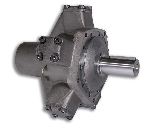
1 Hydraulic Motors Radial Piston Motors with fixed displacement Series RM...X Vg = 250 cm³/u cm³/u Doc.-No. HM3-005 UK
2 Seite 2 Table of contents 1. General Dismantling the distributor unit Dismantling the drive unit Dismantling the cylinder cover Dismantling of a piston / connecting rod subassembly Condition of the parts Setting the taper roller bearings Assembly the drive unit Assembly the distributor unit Starting-up Table of torque / setting torque of bearings... 7
3 Seite 3 1. General Great attention is to be paid to cleanness when dismantling or assembling. Do not use fraying cleaning cloths or cleaning wool. Do not assemble in workshops where cutting or grinding is carried out or where dust occurs. A hoist is required to handle and transport the motors. The weight of the motors is as follows: RM 250X - RM 500X RM 710X - RM 900X approx. 76 kg approx. 132 kg Suitable jacking-up of the motor eases dismantling. If the motor is disconnected from its connecting pipes or opened, then the oil flowing out is to be caught in a suitable container and disposed of according to regulations. Attention is to be paid that the dismantled parts, particularly sliding surfaces and seals, are not dirtied or damaged. It is recommended that the dismantled parts be laid in a table covered with clean oiled paper. The following spare parts list explains the individual parts of the motors: RM 250X RM RM 59.55Ca RM 59.55St RM 355X RM RM 59.55Ca RM 59.55St RM 450X RM RM 59.55Ca RM 59.55St RM 500X RM RM 59.55Ca RM 59.55St RM 710X RM RM 59.60Ca RM 59.58St RM 900X RM RM 59.60Ca RM 59.60St 2. Dismantling the distributor unit Jack the motor in a vertical position with the driveshaft pointing downwards. Remove the allen-type screws (45). Remove the cover plate (47). Remove lockwasher (43.7) using two strong screwdrivers, whereby the bush (46) must be depressed by approx. 1 mm, so that the lockwasher is free of axial pressure and can be eased out with two srcewdrivers. The bush (46) can be extracted by fitting two M8 srews in the tapped holes provided and pulling the bush by the screws. The seals could be damaged and must in each case be replaced prior to fitting.the pressure pad (43.2) with spring (44) and seals (56.1 and 56.2) is in most cases located centrally in the bush and is removed at the same time. Note: All faces of the interior, the bush and the pressure pad are sealing surfaces and must not show any scoring (do not damage). Extract distributor eccentric (43.1) together with roller cage and cylindrical rollers. Control inner ring (41.1) and control outer ring (42) with seals (55.1/55.21, 57.1/57.2), spring discs (43.4) and ball valve (41.2/41.3) to be removed completely. Damage to the distributor (40) occurs only rarely. As special tools and experience is required, please return this item to our works for repair.
4 Seite 4 3. Dismantling the drive unit The motor is jacked-up with the take-off shaft upwards. The oil flowing out is to be caught in a suitable container and disposed of according to regulations. In the case of motors with cylindrical shaft with feather key, then the feather key (11) has to be removed from the crankshaft take off peg. Loosen and remove the bearing cover screws (27). (The screws are glued in and may be very tight, warming may ease unscrewing). Press the bearing cover (21) evenly out of the motor casing (20) by screwing in two cheese head screws (27) in the two opposite taps and remove the o-rings (52) as well as the alignment disc (24). Carefully store the alignment disc for possible use later. If components necessary for bearing settings, e.g. motor casing, taper roller bearings, bearing cover or crankshaft, are not replaced; then the alignment disc (24) may be re-used and the bearings do not have to be re-set in this case. The crankshaft (10) can now be pulled out vertically. In order to do so, a lifting screw is to be screwed into the frontal thread of the crankshaft and the crankshaft carefully pulled out using this screw. The bearing inner disc (26) is to be pushed off the crankshaft when removing the crankshaft. If the bearing ring sticks, hitting the accessible part of the shoulder may facilitate removal. Caution! Be careful not to damage the lower areas of the connecting rod. Then gently pull all the piston and connecting rod units (30) towards the motor casing middle axis, until both connecting rod retaining rings (23) can be removed and take out the upper ring. Then push the piston and connecting rod units (30) outwards until the rear ring can be removed. If necessary, the piston and connecting rod units can be pulled inwards, out of the cylinder ducts. 4. Dismantling the cylinder cover Loosen and remove the cylinder cover screws (28) and lift off the cylinder cover (22). (The screws are glued in and may be very tight, warming may ease unscrewing). 5. Dismantling a piston / connecting-rod subassembly: Clamp the piston firmly (but avoiding damage using a vice with soft jaws). Unscrew the set-screw with hole (35) with a screw driver. This set-screw is glued in and also caulked and thus difficult to loosen! Carefully bore open the pipe (36) with a drill bit size 4,2 mm and cut an M5 thread. Remove the pipe (36) using an M5 screw. Press the bolt (34) out of the piston side. When assembling the bolt (34) in the piston (32), whereby the bolt must also be inserted through the connecting rod eye (31), be careful that the bolt is turned so that the duct in the bolt is fitted in the direction of the connecting rod longitudinal axis. Drive in the pipe (36) through the piston and the duct in the bolt (34) from the head of the piston (32). Degrease the thread in the piston, glue in the set-screw with hole (35) with Loctite 324 or a comparable adhesive and secure additionally by caulking. 6. Condition of the parts Thoroughly clean all parts after dismantling and then examine them to establish whether they can be re-used or not. Particular attention should be paid to the following components: connecting rod eyes and lower areas, connecting rod running surface on the crankshaft (large eccentric diameter), shaft seal slide ways and edges, taper roller bearing slide ways, cylinder duct surfaces and piston surfaces as well as o rings and their supporting rings.
5 Seite 5 The fronts of the bush, the thrust piece, the eccentric, the distributor inner ring and outer ring and the distributor contact surface are all sealing surfaces and should not have any furrows, such damaged parts are to be replaced. If the taper roller bearing slide ways show any pitting, eruptions or other signs of wear then both bearings are to be completely replaced. If the measuring-shaft (64) is damaged then a new unit (crankshaft, measuring-shaft and dowel pin) is to be ordered, since the measuring-shaft (64) is shrunk into the crankshaft (10) and additionally secured with a straight pin (49.3). The dirt stripper (51.1) as well as all o-rings in the distributor including their supporting rings should always be replaced. The order designations and numbers for the parts to be replaced can be seen in the respective spare parts lists. 7. Setting the taper roller bearings Setting the taper roller bearings is always necessary when parts which influence the bearing settings have been replaced, e.g. motor casing, bearing cover, crankshaft or taper roller bearings, or if the original alignment discs are no loner usable or have been lost. Setting the axial initial tension is carried out during assembly using alignment discs. To this end, the crankshaft with the bearings is placed in the motor casing and axially braced by screwing on the bearing cover. The appropriate initial tension is reached by removing or adding individual alignment disc films between the bearing cover and the casing. The moment of friction of the bearing under initial tension serves as the measure for the correct setting. No parts which may influence the result may be fitted in the motor. These include the piston and connecting rod units, the distributor as well as the shaft seals in the bearing cover, that is the radial packing ring cover (only for motors with measuring-shaft). The moment of friction is checked by turning the journal using a dynamometric key. In doing so, it is imperative that the bearing is fitted with the lubrication originally applied by the manufacturer and the shaft is manually turned al least two complete rotations. The correct torque setting can be seen in the table on page 7. The crankshaft is to be dismantled again after bearing setting. 8. Assembly the drive unit Thoroughly clean all parts before assembling and thoroughly degrease the taps in the motor casing for the cylinder cover and bearing cover screws. With regard to sub-assembly of the piston/rod - units see point 5 (above). To assemble the cylinder cover (22), firstly place the supporting rings (54.2) in the space provided and above that the o-ring (54.1) that is towards the inside of the motor. Then place the cylinder cover with its centering shoulder in the motor casing cylinder duct and secure with the 4 cheese head screws (28). These screws are to be grease-free, phosphatised and wetted below the thread with Loctite 324 or a comparable adhesive. The screw torque can be seen in the table on page 10. Repeat this procedure for all other dismantled cylinder covers. Mark the shaft in the rear transition radius of the distributor square with a prick punch if not already thus marked. This is necessary to provide an optical impression of the fitting position relative to the rotational angle of the crankshaft eccentric.
6 Seite 6 Now place the taper roller bearing inner ring (26) in the bearing outer ring in the motor casing and loosely place the rear connecting rod retaining ring in the casing with the smaller inner diameter upwards. Insert the piston and connecting rod units (30) into the cylinder ducts using a special piston ring collet chuck or appropriate piston ring clamp. Place the connecting rod retaining rings (23) in the connecting-rod guide channel and press the connecting rod out completely so that the connecting rod lower areas lie in the rings. Move the rings and connecting rod lower areas into a position externally centered around the crankshaft eccentric. The crankshaft (10) can now be pushed with its rear bearing journal in the taper roller bearing (26) and with the large eccentric diameter in the connecting rod shoes held by the rings (23). Now place the alignment disc (24) required for the taper roller bearing setting in Point 6, on the inner flange of the bearing cover so that the ducts are covered. Then graze the o ring (52) over the bearing cover casing-side centering diameter so that the o-ring comes against the corner with the alignment ring. Then lay a new dirt stripper (51.1) and the spacer ring (51.2) in the bearing cover (21). Now press the shaft seal (51.3) with its dust lip downwards and the seal edge upwards evenly at the circumference of the outer ring into the bearing cover. An appropriate tool is to be used for assembly. The completely assembled bearing cover is to be pushed onto the crankshaft (7) using a conical assembly sleeve on the crankshaft take-off peg, so that the cover screw holes and the motor casing taps are on top of one another. Then remove the assembly sleeve from the shaft. When screwing in the hexagonal socket head screws (27) these screws are to be grease-free, phosphatised and wetted below the thread with Loctite 324 or a comparable adhesive. Tighten the screws evenly crosswise with a dynamometric key. The torque setting can be seen in the table on page 7. For motors with cylindrical take-off shafts with feather key the feather key are now replaced in the take-off shaft pegs. 9. Assembly the distributor Assembly of the control unit in reverse order to dismantling - see 2. Jack motor with the shaft end pointing downwards. Renew all seals of the control unit. Fit completely assembled control ring (items 41.1, 41.2, 41.3, 42, 43.4, 55.1, 55.2, 57.1, 57.2) and according to 7.5 push eccentrically towards the centre axis. Assemble the roller cage (43.5) with the eccentric (43.1). Assemble the cylindrical roller (43.6) in the cage (43.5). Push this assembled unit over the crankshaft. This method of assembly of the distributor provides right-hand rotation, with the flow passing from port 2 to 1. (See catalogue sheet for further details). Care should be taken when assembling the distributor eccentric (43.1), that the upmost point of the distributor eccentric is pushed upwards by 90 to the crankshaft eccentric, (10) to the right of the upmost point of the crankshaft eccentric on the square section of the crankshaft.
7 Seite 7 The upmost point of the crankshaft eccentric is marked by means a punch mark on the face of the square sectionof the control spigot of the crankshaft (when viewed in the direction of the distributor). 10. Starting-up The motor must be filled with hydraulic fluid via a leakage fluid connection before starting up. The motor leakage oil connection is to be positioned so that the casing always remains full of hydraulic fluid. Leakage from the radial piston motor must be returned to the tank separately from runback and from other users, to avoid retained pressure. The leakage pressure measured directly at the leakage fluid connection should not exceed 1 bar. The entire hydraulic system should be completely vented to ensure faultless operation of the motor. When starting up the motor, do not operate immediately at maximum pressure and / or maximum speed, but allow newly fitted parts time to settle or run in. Recommendation for the first hours of operation: Pressure approx. Speed approx bar rpm Optimum running properties only occur after a running-in phase of approx hours. 11. Table of torque / setting torque of bearings Torque (Nm) Comment RM 250X - RM 500X Screw (27) 65 Bearing cover Screw (28) 85 Cylinder cover Screw (45) 25 End cover RM 710X - RM 900X Screw (27) 65 Bearing cover Screw (28) 210 Cylinder cover Screw (45) 25 End cover RM 250X - RM 500X Bearing setting torque 1,0-3,0 RM 710X - RM 900X Bearing setting torque 1,5-4,0


8 DÜSTERLOH has been developing fluid technology products for more than 100 years. The drives, controls and hydraulic power units from Hattingen are appreciated throughout the world for their complete reliability; including under extreme conditions. The owner-managed company s own development and construction department and the wide range of products cater for distinctive flexibility and customer-orientation. Products Hydraulic radial piston motors Hydraulic axial piston motors Pneumatic motors Pneumatic starters Hydraulic and pneumatic controls Hydraulic power units Designing controls and hydraulic power units specific to the customer is our company s major strength. Vast product diversity is also available for standardized products. Industrial areas of application Machine tools Smelting and rolling mill equipment Foundry machines Testing machines Shipbuilding (diesel engines) Offshore technology Printing and paper technology Vehicle construction Manipulators Environmental technology Mining equipment Materials handling equipment Düsterloh Fluidtechnik GmbH Im Vogelsang 105 D Hattingen Tel.: Fax: info@duesterloh.de Internet: Certified acc. to ISO 9001
Hydraulic Motors. Radial Piston Motors Precision drives with fixed displacement RM 80N... - RM 250N... series Vg = 80 ccm/rev ccm/ccm
 Hydraulic Motors Radial Piston Motors Precision drives with fixed displacement RM 80N... - RM 250N... series Vg = 80 ccm/rev - 250 ccm/ccm Repair Manual Doc.-No. HM3-013 UK Seite 2 Table of contents 1.
Multiple disc brakes. pressure released and spring operated multiple disc brakes series LBD T brake. Installation- operating instructions
 Multiple disc brakes pressure released and spring series LBD T brake = 50 Nm - 6300 Nm for dry or wet operation as well as for hardly combustible hydraulic fluids HFA, HFB, HFC and HFD Installation- operating
Pneumatic-Motors Accessories catalog DMO - PMW pneumatic gearwheel motors and spur gear motors
 Pneumatic-Motors Accessories catalog DMO - PMW pneumatic gearwheel motors and spur gear motors Dok.-Nr. M1-009 UK Contents accessories catalog Page 2 Designation... page Contents... 02 Ball valve PN 25...
Maintenance Information
 45528270 Edition 1 June 2007 Barring Motor T480 Series Maintenance Information Save These Instructions WARNING Always wear eye protection when operating or performing maintenance on this Barring Motor.
HYDRAULIC-MOTORS. Radial Piston Motors with fixed displacement RM...X series V g = 250 cm 3 /rev cm 3 /rev
 s with fixed displacement RM...X series V g = 250 cm 3 /rev - 900 cm 3 /rev HYDRAULIC-MOTORS Catalogue No. HM1-015E RM 250X - RM 900X Page 2 Features: many displacements for all applications very high
SAI GM Series Piston Hydraulic Motor Crankshaft Design Radial Piston Motors
 SAI GM Series Piston Hydraulic Motor Crankshaft Design Radial Piston Motors www.chinawinches.cn (Dimension: inch) Brief Performance Table of Sai GM Series Piston Hydraulic Motor (Full range GM05- GM9 series)
Pneumatic Motors. Pneumatic Motors PMW PMW 530. Installation- operating instructions. Katalog-Nr.: A UK
 Pneumatic Motors Pneumatic Motors PMW 160 - PMW 530 Installation- operating instructions Katalog-Nr.: Contents PMW 160 - PMW 530 Page 2 Contents Designation... Page Transportation- and storing instructions...
ORIGA SYSTEM PLUS Guides, Brakes and Valves for Modular Linear Drive Systems OSP Appendix to the Operating Instructions
 ORIGA SYSTEM PLUS Guides, Brakes and Valves for Modular Linear Drive Systems OSP Appendix to the Operating Instructions TAll personnel who have anything to do with the OSP fitted with guides, brakes or
1988 Chevrolet Pickup V SUSPENSION - FRONT (4WD)' 'Front Suspension - "V" Series 1988 SUSPENSION - FRONT (4WD) Front Suspension - "V" Series
' 'Front Suspension - V Series 1988 SUSPENSION - FRONT (4WD) Front Suspension - V Series") 1988 SUSPENSION - FRONT (4WD) Front Suspension - "V" Series DESCRIPTION NOTE: Vehicle serial numbers used in this article has been abbreviated for common reference to Chevrolet and GMC models. Chevrolet
1988 SUSPENSION - FRONT (4WD) Front Suspension - "V" Series DESCRIPTION NOTE: Vehicle serial numbers used in this article has been abbreviated for common reference to Chevrolet and GMC models. Chevrolet
Standard Parts for Mould Making
 Standard Parts for Mould Making Index Your Production Partner 4-5 Guide Elements Locating units, round 8 Locating units, flat 8 Compensation Discs 9 Adjusting washers 9 Ejector rods 10 Centering sleeves
1984 Dodge W250 PICKUP
 1984 Dodge W250 PICKUP Submodel: Engine Type: V8 Liters: 5.2 Fuel Delivery: CARB Fuel: GAS Dana 44 MODELS THROUGH 1984 2. Raise and safely support the vehicle, then remove the wheel hub and bearings as
Hydraulic Rotary Hammer Drill
 M a s c h i n e n f a b r i k G m b H Hydraulic Rotary Hammer Drill Type 2 2406 0010 Techn. Doc. No. 262 Illustration can differ from the original Repair Manual and Spare Parts List 224060010_Inst_en_Version_06.doc
Dismounting. Removing seals Removing non-contact seals Removing contact seals
 Dismounting Dismounting rolling bearings... 254 What to remember... 254 Preparations prior to dismounting... 254 Appropriate dismounting methods... 255 Dismounting a bearing fitted on a cylindrical shaft
Drive pinion and ring gear,
 Page 1 of 38 39-166 Drive pinion and ring gear, adjusting General notes: Drive pinion and ring gear must be very carefully adjusted to ensure long service life and smooth running. At the factory, drive
INSTRUCTIONS FOR OVERHAUL OF RAMEY RE SERIES WINCH
 INSTRUCTIONS FOR OVERHAUL OF RAMEY RE 12000 SERIES WINCH DISASSEMBLY 1. Drain oil from gear housing by removing plug # from bottom of gear housing. Remove relief fitting # and reducer # from top of gear
Sisu S-Cam Drum Brakes
 Sisu S-Cam Drum Brakes (For hub reduction rear axles since 1992) Maintenance Manual Sisu Axles, Inc. Autotehtaantie 1 P.O. Box 189 FIN-13101 Hämeenlinna Finland Phone int + 358 204 55 2999 Fax int + 358
Maintenance Information
 16572679 Edition 2 May 2014 Air Drill QP Series Maintenance Information Save These Instructions Product Safety Information WARNING Failure to observe the following warnings, and to avoid these potentially
Engine Dismantle and Assemble ( )
") Engine Dismantle and Assemble (2 34 8) Special Tools 2-036A Remover for pilot bearing 2-37 Oil seal installer/aligner 237 2036A 2-044A Installer/Aligner, Pilot Bearing/Clutch Plate 244 2-44 Inlet manifold
Engine Dismantle and Assemble (2 34 8) Special Tools 2-036A Remover for pilot bearing 2-37 Oil seal installer/aligner 237 2036A 2-044A Installer/Aligner, Pilot Bearing/Clutch Plate 244 2-44 Inlet manifold
Engine Dismantle and Assemble ( )
") Engine Dismantle and Assemble ( 34 8) Special Tools 5 053 Slide hammer 47 Vibration damper remover 47 5053 00 Splined head socket, cylinder head bolts 87 Mounting stand with geared drive 00 059C Installer
Engine Dismantle and Assemble ( 34 8) Special Tools 5 053 Slide hammer 47 Vibration damper remover 47 5053 00 Splined head socket, cylinder head bolts 87 Mounting stand with geared drive 00 059C Installer
Husqvarna Hedgetrimmers 325HS/ 325HE/ 325HDA. Workshop manual
 Husqvarna Hedgetrimmers 325HS/ 325HE/ 325HDA Workshop manual 101 90 73-26 2 Workshop Manual Hedge trimmers Supplement for models 325HS, 325HE,325HDA Contents 1. Starter 5 2. Ignition system 7 3. Fuel system
Dismantling and assembling transmission
 27-640 Dismantling and assembling transmission Operation number of the operation texts and work units or standard texts and flat rates: 27-4010 P27-5367-61 Control pressure cable (98) Slacken, remove and
Guide units. For toolmaking, fixture manufacturing and machine engineering
 Guide units For toolmaking, fixture manufacturing and machine engineering Guide units in compliance with DIN, ISO and STEINEL standards or according to your specifications Guide pillars Guide and pillar
DRIVE AXLE Volvo 960 DESCRIPTION & OPERATION AXLE IDENTIFICATION DRIVE AXLES Volvo Differentials & Axle Shafts
 DRIVE AXLE 1994 Volvo 960 1994 DRIVE AXLES Volvo Differentials & Axle Shafts 960 DESCRIPTION & OPERATION All 960 station wagon models use type 1041 rear axle assembly. All 960 4-door models use type 1045
PACKING, HANDLING, TRANSPORTING AND STORING MOTORS
 PACKING, HANDLING, TRANSPORTING AND STORING MOTORS Make sure that the shaft of the motor is not loaded in any way and is protected from knocks. Axial loads or shocks may easily damage the bearings inside
Maintenance Information
 80234313 Edition 1 June 2006 Air Grinder, Die Grinder, Sander and Belt Sander Series G1 (Angle) Maintenance Information Save These Instructions WARNING Always wear eye protection when operating or performing
 Page 1 of 15 Transmission, Model S5-42 ZF Model S5-42 ZF Disassembly NOTE: For 4x4 and F-Super Duty vehicles, skip to Step 5. 1. Attach the transmission to the Bench Mounted Holding Fixture T57L-500-B
Valvetrain, servicing
 Page 1 of 51 15-32 Valvetrain, servicing Note: Cylinder heads with small cracks between the valve seats that are less than 0.3 mm (0.012 in.) wide and/or between one valve seat and only the first 4 threads
Transmission Overhaul Procedures-Bench Service
 How to Assemble the Lower Reverse Idler Gear Assembly Special Instructions In 1996 Eaton changed the reverse idler system design. In the nut design, the reverse idler bearing was lubricated through a hole
INSTRUCTION MANUAL AND PARTS LIST FOR SERIES 8L-630J AND 630M WARNING
 INSTRUCTION MANUAL AND PARTS LIST FOR SERIES 8L-630J AND 630M WARNING READ CA-l AND TIDS INSTRUCTION MANUAL PRIOR TO INSTALLATION, OPERATION OR MAINTENANCE WARNING This Instruction Manual and General Instructions
PAN 17 MECHANICAL SLIDING CALLIPER DISC BRAKE ASSEMBLY AND MAINTENANCE INSTRUCTIONS
 PAN 17 MECHANICAL SLIDING CALLIPER DISC BRAKE ASSEMBLY AND MAINTENANCE INSTRUCTIONS PAN 17 MECHANICAL SLIDING CALLIPER DISC BRAKE Assembly and Maintenance Instructions 2nd edition This publication is
Repair Manual and Spare Parts List
 Pneumatic Drive Unit Type Techn. Doc. No. 352 and Accessories for Pipe Cutting Machine Darstellung kann vom Original abweichen Repair Manual and 580027000_Inst_en_Version_02 Repair General In general,
Maintenance Information
 16573370 Edition 2 February 2014 Air Grinder 99V Series Maintenance Information Save These Instructions Product Safety Information WARNING Failure to observe the following warnings, and to avoid these
DYNACTAIR 200 to MAINTENANCE
 Maintenance 8519.83/3--EN DYNACTAIR 200 to 800 - MAINTENANCE INSTALLATION MAINTENANCE 1 - General overview 2 - Recommended tools 3 - Installation / Safety / Exhaust ports of springs cartridges 4 - Adjustment
Maintenance Information
 80234313 Edition 2 May 2014 Air Grinder, Die Grinder, Sander and Belt Sander Series G1 (Angle) Maintenance Information Save These Instructions Product Safety Information WARNING Failure to observe the
FRICTIONAL CONNECTIONS CATALOGUE
 FRICTIONAL CONNECTIONS CATALOGUE Reprinting and all other forms of copying, not even partially, is prohibited without permission from Stüwe. Maschinenfabrik GmbH & Co. KG Production: Studio Salewski GmbH,
Maintenance Information
 Form 16573321 Edition 1 July 2004 Air Grinder Series 61H Maintenance Information Save These Instructions Always wear eye protection when operating or performing maintenance on this tool. Always turn off
SECTION H STEERING. Section Description Page No. H.1 GENERAL DESCRIPTION 3 H.2 STEERING WHEEL 3 H.3 INNER COLUMN 5 H.
 SECTION H STEERING Section Description Page No. H.1 GENERAL DESCRIPTION 3 H.2 STEERING WHEEL 3 H.3 INNER COLUMN 5 H.4 OUTER COLUMN 5 H.5 STEERING UNIT LOCK STOPS 6 H.6 STEERING UNIT 6 H.7 STEERING ARMS
Repair Manual and Spare Parts List
 Hydraulic Drive Unit Type Techn. Doc. No. 362 and Accessories for Pipe Cutting Machine Darstellung kann vom Original abweichen Repair Manual and 580067000_Inst_en_Version_03 Repair General In general,
ZE ZE ZE. Simplex expanding wedge brake Assembly and Maintenance Instructions
 Simplex expanding wedge brake Assembly and Maintenance Instructions Simplex expanding wedge brake Assembly and Maintenance Instructions Edition 1 This publication is not subject to any update service.
Final drive gear set, recommended sequence for adjusting
 Page 1 of 31 39-148 Final drive gear set, recommended sequence for adjusting If the pinion shaft and ring gear have to be readjusted, the following sequence is recommended for maximum efficiency: 1.) Determine
Maintenance Information
 16573321 Edition 3 February 2014 Air Grinder Series 61H Maintenance Information Save These Instructions Product Safety Information WARNING Failure to observe the following warnings, and to avoid these
Mechanical Sliding Caliper Disc Brake. Type PAN 19-1 Assembly and Maintenance Instructions
 WABCO Mannheim Mechanical Sliding Caliper Disc Brake Type PAN 19-1 Assembly and Maintenance Instructions WABCO Radbremsen GmbH Postfach 71 02 63 D-68222 Mannheim Bärlochweg 25 D-68229 Mannheim +49 (0)6
Maintenance Instructions
 General Note These instructions contain information common to more than one model of Bevel Gear Drive. To simplify reading, similar models have been grouped as follows: GROUP 1 Models 11, 0, 1,, (illustrated),,
TROUBLESHOOTING SPECIAL TOOL ASSEMBLY AND ADJUSTMENT
 1 INDEX Models FD, FE, FF and SG REAR AXLE 10-1 10-108E-07 CHAPTER 10 REAR AXLE Models FD, FE, FF and SG TROUBLESHOOTING...10-2 10 SPECIAL TOOL...10-3 WHEEL HUB AND RELATED PARTS DISASSEMBLY...10-7 INSPECTION...10-9
INSTALLATION AND MAINTENANCE OF TOP LOADING ARM
 INSTALLATION AND MAINTENANCE OF TOP LOADING ARM D TABLE OF CONTENTS 1. INTRODUCTION 04 2. SPECIFICATION OF THE REDLANDS LOADING ARM 04 3. INSTALLING THE LOADING ARM 3.1. Installation Procedures 05 4.
Guides, Brakes and Valves
 Guides, Brakes and Valves Operating Instructions ORIGA SYSTEM PLUS Appendix to the Operating Instructions OSP-P / OSP-E Guides, Brakes and Valves OSP-P / OSP-E Content 1 Foreword to the Operating Instructions
BOLT TENSIONERS. carefully before use and retain it for reference.
 BOLT TENSIONERS This manual contains IMPORTANT WARNINGS, CAUTIONS and other instructions. Read and understand the instructions manual carefully before use and retain it for reference. TORCUP MIDDLE EAST
 AUTOGARD SERIES 820 TORQUE LIMITER Installation and Maintenance Manual DB0009 Issue 11 21 Feb 2017 British Autogard Ltd 2 Wilkinson Rd., Love Lane Industrial Estate, Cirencester, Glos., GL7 1YT UK Tel.
Engine Dismantle and Assemble ( )
") Engine Dismantle and Assemble (21 134 8) Special Tools 15-030A Universal flange-holding wrench 21147 21-147 Vibration damper remover 15030A 16-067 Locator for clutch disc 21-167 Wrench for cylinder head
Engine Dismantle and Assemble (21 134 8) Special Tools 15-030A Universal flange-holding wrench 21147 21-147 Vibration damper remover 15030A 16-067 Locator for clutch disc 21-167 Wrench for cylinder head
Maintenance Information
 16606022 Edition 3 May 2014 Air Drill 728 Series Maintenance Information Save These Instructions Product Safety Information WARNING Failure to observe the following warnings, and to avoid these potentially
Pneumatic Axial Die Grinder also for Underwater Use Type , 0050
 M a s c h i n e n f a b r i k G m b H Pneumatic Axial Die Grinder also for Underwater Use Type 1 5077 0010 0020, 0050 Illustration can differ from the original Repair Manual and Compiled: 18.07.11 150770010_0020_0050_Inst_en_Version_00
Servicing the Tool. Service Kit SERVICE KIT. For all servicing we recommend the use of the service kit (part number (S)).
).") Servicing the Tool Service Kit For all servicing we recommend the use of the service kit (part number 07900-04750(S)). SERVICE KIT ITEM PART Nº DESCRIPTION Nº OFF ITEM PART Nº DESCRIPTION Nº OFF 07900-00002
Servicing the Tool Service Kit For all servicing we recommend the use of the service kit (part number 07900-04750(S)). SERVICE KIT ITEM PART Nº DESCRIPTION Nº OFF ITEM PART Nº DESCRIPTION Nº OFF 07900-00002
Maintenance Information
 04581245 Edition 2 May 2014 Air Grinder, Die Grinder and Sander Series G2 (Angle) Maintenance Information Save These Instructions Product Safety Information WARNING Failure to observe the following warnings,
Maintenance Information
 45761848 Edition 3 February 2014 Air Die Grinder AC4A, SC4A and XC4A Series Maintenance Information Save These Instructions Product Safety Information WARNING Failure to observe the following warnings,
Valtek Auxiliary Handwheels and Limit Stops
 Valtek Auxiliary s and Limit Stops Table of Contents Page 1 General information 2 Installation 2 Side-mounted handwheels, size 25 and 50 (linear actuators) 3 Side-mounted handwheels, size 100 and 200 (linear
ACTAIR 400 to MAINTENANCE
 Maintenance 8510.84/2--EN ACTAIR 400 to 1600 - MAINTENANCE INSTALLATION MAINTENANCE - General over view - Tooling - Installation - Adjustement of opening or closing adjustable end stops - Actuator dysassembly
TRANSMISSION 6.7 GENERAL HOME. See Figure The transmission is a five-speed constantmesh type housed in an extension of the crankcase.
 TRANSMISSION 6.7 GENERAL See Figure 6-45. The transmission is a five-speed constantmesh type housed in an extension of the crankcase. Mainshaft Neutral Mainshaft st Gear b06x6x Countershaft 4 Out 5 Countershaft
Sub Section Title Page No.
 Sub Section Title Page No. 1 Introduction 3 2 Routine Maintenance 3 3 Disassembly 4 3.1 Disassembly of Double Crank Design 4 3.2 Disassembly of Scotch Yoke Design 5 3.3 Disassembly of Actuator Cylinder
HKS 700E. Service Manual June Ver. 2.04
 HKS 700E Service Manual 009 June Ver..04 HKS CO.,LTD 78 KITAYAMA FUJINOMIYA SHIZUOKA JAPAN 48-09 TEL +8(0)544-54-78 FAX +8(0)544-54-40 hks_aviation@hks-power.co.jp http://www.hks-power.co.jp/hks_aviation/
OVERHAUL 1. REMOVE CYLINDER BLOCK WATER DRAIN COCK SUB ASSY
 1416 OVERHAUL 1. REMOVE CYLINDER BLOCK WATER DRAIN COCK SUBASSY 140RL01. INSPECT CONNECTING ROD THRUST CLEARANCE (a) Using a dial indicator, measure the thrust clearance while moving the connecting rod
Maintenance Information
 16575128 Edition 2 May 2014 Air Grinder, Sander or Polisher 77A Series Maintenance Information Save These Instructions Product Safety Information Failure to observe the following warnings, and to avoid
2003 Hyundai Sonata LX
 TIMING & COUNTERBALANCE SHAFT BELTS Removal CAUTION: DO NOT rotate engine counterclockwise (as viewed from timing belt end of engine). If reusing timing belt, place reference mark on timing belt to indicate
3.2 DRIVE TORQUE HUB. Roll, Leak and Brake Testing SECTION 3 - CHASSIS & TURNTABLE. 3-2 JLG Lift
 3.2 DRIVE TORQUE HUB Roll, Leak and Brake Testing 10 LUG PATTERN Torque-Hub units should always be roll and leak tested before disassembly and after assembly to make sure that the unit's gears, bearings
3 Axles and brakes. 3.1 Function and construction of the axles Construction Function
 3 Axles and brakes 3.1 Function and construction of the axles 3.1.1 Function Each wheel has an independent suspension system in the axle body (1), so that individual wheel suspension is provided. The swinging
Stem Assembly Supplement
 Installation, Operating & Maintenance Instructions Assembly Supplement Envirosafe Cryogenic & Low Temperature O-Ring as FM 00707 Cryogenic & Low Temperature Valves: This section contains only details of
Maintenance Information
 Form 04584058 Edition 1 November 2004 Air Impactool 2141P and 2141PSP Maintenance Information Save These Instructions Disassembly General Instructions 1. Do not disassemble the tool any further than necessary
Westingh'ouse Steam Turbines-I. B (Rev. 3) GOVERNOR, GOVERNING VALVE
 GOVERNOR, GOVERNING VALVE") Supersedes l. B. 697 (Rev. 2) Westingh'ouse Steam Turbines-I. B. 697 (Rev. 3) GOVERNOR, GOVERNING VALVE AND OIL PUMP This governor mechanism comprises a vertical shaft centrifugal weight governor a gear
Supersedes l. B. 697 (Rev. 2) Westingh'ouse Steam Turbines-I. B. 697 (Rev. 3) GOVERNOR, GOVERNING VALVE AND OIL PUMP This governor mechanism comprises a vertical shaft centrifugal weight governor a gear
Competence from the Original Equipment Supplier
 Workshop Tips Competence from the Original Equipment Supplier GKN Driveline is the world s leading supplier of automotive driveline components and systems. Our global market leadership is based on a strong
Maintenance Information
 16575243 Edition 2 October 2013 Air Screwdrivers 1R Series Maintenance Information Save These Instructions Product Safety Information WARNING Failure to observe the following warnings, and to avoid these
Assembly Instructions and Handling Regulations for KLINGER. Piston Valves KVN DN VI,VIII and Regulating Piston KVRLN DN , PN 40 VI, VIII
 Page 1 Assembly Instructions and Handling Regulations for KLINGER Piston Valves KVN DN 65-200 VI,VIII and Regulating Piston KVRLN DN 65-200, PN 40 VI, VIII pressure released type with valve ring KX-GT
OVERHAUL. Remove the union bolt and a gasket from the disc brake cylinder, then disconnect the flexible hose from the disc brake cylinder.
 OVERHAUL COMPONENTS: See page 3232 Overhaul the RH side by the same procedures with LH side. Two types of brake pad exist; one is with slit and the other without slit. 1. REMOVE REAR WHEEL 2. DRAIN FLUID
1. General Description
 General Description 1. General Description A: SPECIFICATION Front Rear Model Wheel arch height (Tolerance: +12 mm 24 mm ( +0.47 in 0.94 in)) mm (in) 376 (14.8) Camber (Tolerance: 0 45 Differences between
Installation Instructions
 Preparing your vehicle to install your brake system upgrade 1. Rack the vehicle. 2. If you don t have a rack, then you must take extra safety precautions. 3. Choose a firmly packed and level ground to
Instruction Manual for HSPA Take-Up Units
 Installation Instruction Manual for HSPA Take-Up Units Warning: To ensure the drive is not unexpectedly started, turn off and lockout the power source before proceeding. Failure to observe these precautions
DRIVE AXLE Nissan 240SX DESCRIPTION & OPERATION AXLE RATIO & IDENTIFICATION AXLE SHAFT & BEARING R & I DRIVE SHAFT R & I
 DRIVE AXLE 1990 Nissan 240SX 1990 DRIVE AXLES Rear Axle - R200 240SX, 300ZX DESCRIPTION & OPERATION The axle assembly is a hypoid type gear with integral carrier housing. The pinion bearing preload adjustment
PLACING THE MOTOR IN SERVICE
 04579413 Form P7620 Edition 1 May, 2003 OPERATION AND MAINTENANCE MANUAL for SM2AM AIR MOTOR (Dwg. MHP2541) IMPORTANT SAFETY INFORMATION ENCLOSED - SAVE THESE INSTRUCTIONS READ AND UNDERSTAND THIS MANUAL
PROPELLER SHAFT & DIFFERENTIAL CARRIER SECTIONPD CONTENTS
 PROPELLER SHAFT & DIFFERENTIAL CARRIER SECTIONPD CONTENTS PREPARATION...2 PROPELLER SHAFT...5 On-Vehicle Service...6 Removal and Installation...7 Inspection...7 Disassembly...7 Assembly...8 ON-VEHICLE
Fitting-removal and maintenance
 Fitting-removal and maintenance Fitting of bearings 136 General rules 136 Fitting principles 136 Hot fitting 137 Press fitting (or with anti-rebound hammer) 138 Adapter sleeves 139 Removal of bearings
HGM-E LSHT Wheel Motor Service and Repair Manual
 HGM-E LSHT Wheel Motor Service and Repair Manual BLN-52198 January 2018 Table Of Contents Foreword... 1 How to use this manual... 2 General Instructions... 2 General Description... 2 Tools... 3 Torques...
STAND FOOT - STAND TUBE
 Mounting instructions Directions for use STAND FOOT - STAND TUBE Stand lamps: Mach 130 / Mach 130F Soloflex Triaflex / Triaflex R96 Trigenflex / Trigenflex R96 GmbH u. Co., Flossmannstrasse 28, D-85560
Series 100 Slam Shut Valve
 IMP 8775 Series 00 Slam Shut Valve Sizes ", ", 4" Installation & Maintenance Instructions Read carefully and follow all instructions shipped with this regulator. The incorrect installation of this equipment
ACROBAT SWING STAND MODEL
 Mounting instructions Directions for use ACROBAT SWING STAND MODEL Dr. Mach GmbH u. Co.KG, Flossmannstrasse 28, D-85560 Ebersberg Tel.: +49 (0)8092 2093 0, Fax +49 (0)8092 2093 50 Internet: www.dr-mach.com,
TRANSMISSION 6.7 GENERAL HOME. See Figure The transmission is a five-speed constantmesh type housed in an extension of the crankcase.
 TRANSMISSION 6.7 GENERAL See Figure 6-46. The transmission is a five-speed constantmesh type housed in an extension of the crankcase. b06x6x Neutral st Gear Mainshaft Mainshaft 4 5 4 5 Countershaft Out
Pneumatic Angle Grinder also for Underwater Use Type
 M a s c h i n e n f a b r i k G m b H Pneumatic Angle Grinder also for Underwater Use Type 1 4311 0050 Illustration can differ from the original Repair Manual and Spare Parts List Compiled: 22.06.11 143110050_Inst_en_Version_00
For advanced drive technology CLAMPEX. Shaft-hub-connection. KTR Precision joints CLAMPEX
 technology CLAMPEX Shaft-hub-connection CLAMPEX KTR Precision joints 227 technology Table of contents Page Brief information 228 Selection and calculation 25-255 CLAMPEX -Selection Shaft diameter = d 0
Maintenance Information
 Form 16575334 Edition 1 April 2005 Electric Screwdrivers EL, EP and ET 34V DC Series Maintenance Information Save These Instructions WARNING Maintenance procedures have the potential for severe shock hazard
Removing and installing cylinder head
 31 30 29 28 27 26 25 24 23 22 1 2 3 11 12 10 4 9 5 6 7 8 Removing and installing cylinder head Checking compression pressure page 15-24. Notes: When installing a replacement cylinder head with a mounted
Instructions for Assembling Driving Wheels, Axles and Crankpins
 Instructions for Assembling Driving Wheels, Axles and Crankpins (Version 1; October 2008) Introduction These instructions explain how to assemble Exactoscale 4mm scale driving wheels, axles and crankpins
TC20 Chain Driven Power Take-Off Overhaul Instructions
 TC20 Chain Driven Power Take-Off Overhaul Instructions Table of Contents Section Page Introduction 4 Ordering Repair Parts 4 General Information 5 Special Tools 6 Disassembly See Page 2 Reassembly See
Operating and Maintenance Instructions. Abteilung TB, Schell Seite 1 8 SERIES 56
 Abteilung TB, Schell Seite 1 8 These instructions supersede all earlier instructions, in particular BWS 109-0 till BWS 109-3. For applications in areas with explosion hazard it is obligatory to observe
2006 MINI Cooper SUSPENSION Wheels & Tires - Repair Instructions - Cooper (1.6L) R50/W10 & Cooper S
 R50/W10 & Cooper S") WHEELS 2002-05 SUSPENSION Wheels & Tires - Repair Instructions - Cooper (1.6L) R50/W10 & Cooper S 36 10 300 REMOVING OR INSTALLING FRONT OR REAR WHEEL NOTE: For Special Tool identification, see WHEEL AND
WHEELS 2002-05 SUSPENSION Wheels & Tires - Repair Instructions - Cooper (1.6L) R50/W10 & Cooper S 36 10 300 REMOVING OR INSTALLING FRONT OR REAR WHEEL NOTE: For Special Tool identification, see WHEEL AND
Axial-radial cylindrical roller bearings
 Axial-radial cylindrical roller bearings Designs and variants.............. 320 Bearing data..................... 321 (Boundary dimensions, tolerances) Product table 5.1 Axial-radial cylindrical roller
W BW GW. Workshop manual. Mechanical suspensions BPW, series ECO Cargo W / BW / GW. BPW-WH-W-BW-GW e
 W BW GW Workshop manual Mechanical suspensions BPW, series ECO Cargo W / BW / GW BPW-WH-W-BW-GW 35251401e Page 2 BPW-WH-W-BW-GW 35251401e BPW-WH-W-BW-GW 35251401e Page 3 Contents 1. Product identification...
Bearings. Rolling-contact Bearings
 Bearings A bearing is a mechanical element that limits relative motion to only the desired motion and at the same time it reduces the frictional resistance to the desired motion. Depending on the design
Maintenance Information
 45530136 Edition 1 July 2008 Electric Screwdrivers EL 24V DC Series Maintenance Information Save These Instructions WARNING Always wear eye protection when operating or performing maintenance on this tool.
Volkswagen New Beetle Body - Exterior 64 Glass, Window regulators (Page GR-64)
") 64 Glass, Window regulators (Page GR-64) Flush bonded windows Body flange, preparing for glass installation Broken rear window, removing Cleaning off excess adhesive material Curing time Installation instructions
64 Glass, Window regulators (Page GR-64) Flush bonded windows Body flange, preparing for glass installation Broken rear window, removing Cleaning off excess adhesive material Curing time Installation instructions
Installation Instructions for disc brakes
 Installation Instructions for disc brakes Bedford CF 230-280, built 1974-1986, not suitable for vehicles with rear twin tyres Included 2 pcs. Wheel Hubs with Wheel Bolts, Mounted Brake Discs and Wheel
Accessories, spare parts and measuring equipment
 Accessories, spare parts and measuring equipment The broad range of accessories, spare parts and measuring equipment represents a useful addition to the range of actual clamping tools and offers spare
Spring-Engaged/Hydraulically-Released BD Caliper Brake. (i) MTY (81) QRO (442) MEX (55)
 MTY (81) QRO (442) MEX (55)") Spring-Engaged/Hydraulically-Released BD Caliper Brake (i) FORM NO. L-07-E-0300 In accordance with Nexen s established policy of constant product improvement, the specifications contained in this manual
Spring-Engaged/Hydraulically-Released BD Caliper Brake (i) FORM NO. L-07-E-0300 In accordance with Nexen s established policy of constant product improvement, the specifications contained in this manual
STERNDRIVE UNIT 3 B GEAR HOUSINGS MR/ALPHA ONE/ALPHA ONE SS
 STERNDRIVE UNIT 3 B 23146 GEAR HOUSINGS MR/ALPHA ONE/ALPHA ONE SS Table of Contents Page Identification........................... 3B-1 Specifications.......................... 3B-1 Torque Specifications................