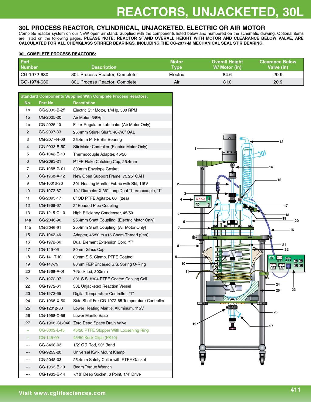
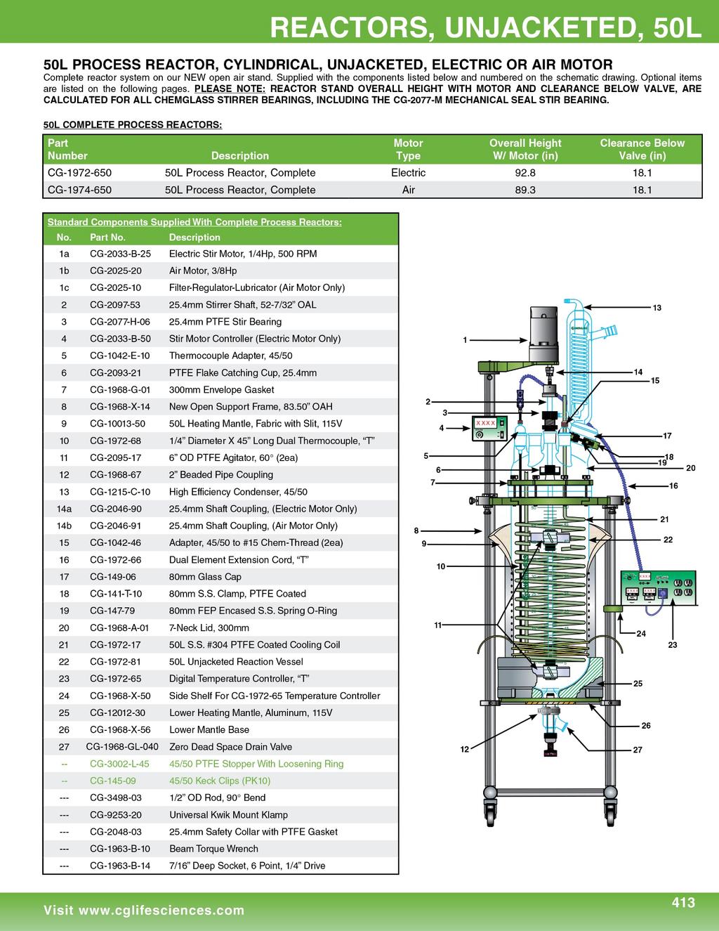
ASSEMBLY INSTRUCTIONS FOR 30L & 50L UNJACKETED PROCESS REACTOR SYSTEMS
|
|
|
- Dorothy Marjorie Cook
- 5 years ago
- Views:
Transcription


1 3800 N. Mill Road Vineland, NJ Phone: Fax: ASSEMBLY INSTRUCTIONS FOR 30L & 50L UNJACKETED PROCESS REACTOR SYSTEMS Motor Mount Arm can Unlock and Swing Out, Giving Greater Access to Reactor Open Frame Design Provides Excellent Accessibility Electric and XP Motors have Separate Controller with Digital Display Smaller Footprint Support Frame with Two Oversized Rugged S.S. Uprights and Heavy Duty PTFE Coated Aluminum Fittings Digital Temperature Controller Stainless Steel Support Shelf Safety Support/ Manifold Support 7-Neck Lid with Large Powder Addition Port Reactor Support Plate Holds Reactor Securely and Allows Easy Installation/Removal of Reactor by One Person Upper and Lower Heating Mantles Zero Dead Space Detachable Drain Valve has Knob with Laser Etched Directional Arrows for Open & Close Heavy Duty Lockable Casters

2 Read Entire Assembly Instructions Before You Begin. Familiarize Yourself with All of the Parts, and Pay Close Attention to All Notes and Highlights. Support frames are shipped via common carrier and require loading dock access with a fork lift or jack. If you do not have a loading dock, then a lift gate-equipped truck must be requested at the time of order. For your convenience, the unjacketed process reactor, the fully assembled reactor head, stirrer shaft & agitators, Tru-Stir stirrer shaft coupling, flake catching cup, PTFE stirrer bearing, temperature probe & adapter, and motor are shipped assembled on the support frame. PTFE sleeves and keck clips are available separately. Unpack all of the parts and check against the packing slip to make sure you have received all necessary components. If possible, keep some of the packaging materials from the wood crates in case you need to return items for repair or replacement. Crate # 1: Unpack the support frame with reactor and components by removing the packing material from around the reactor. Contains the 1/4 HP electric stirrer motor, condenser, zero dead space drain valve, temperature monitor, monitor controller, and other miscellaneous parts. Retighten all of the Allen screws with the supplied wrenches. CHECK ALL ALLEN SCREWS BEFORE PROCEEDING; SCREWS CAN LOOSEN DURING SHIPMENT. Move the reactor assembly and parts near the hood or area where the reactor will be used, but allow enough space to move freely around the support frame. During setup, preparation, and process, it is best to keep the wheels in their locked position by stepping down on the tab. Motor Mount Arm CG-2046 Stirrer Shaft Coupling Universal Motor Mount Arm The universal motor mount arm can unlock and swing out giving greater access to the reactor and peripheral glassware.

 1ea CG-2033-B-50 Digital Electric Stirrer Motor Controller (Only Supplied with 1/4 HP Electric Stirrer Motor) 1ea CG-2046-90 Universal Stirrer Shaft Coupling 1ea CG-9253-20 Large")
 electric, air, or optional explosion proof (XP) motor. The mount automatically centers the motor directly above the reactor. 2.")

3 Overhead Stirrer Motor Air Motor 1/4 HP Vertical Motor 1/4 HP Horizontal Motor Explosion Proof (XP) Motor The motor is installed on the support frame when shipped. Use the following instructions should you need to remove or adjust these components. Components Needed for Overhead Stirrer Motor: 1ea CG-2033-B-25 1/4 HP Vertical Electric Stirrer Motor 1ea CG /4 HP Horizontal Electric Stirrer Motor 1ea CG Air Motor* (Optional) 1ea CG-2033-B-50 Digital Electric Stirrer Motor Controller (Only Supplied with 1/4 HP Electric Stirrer Motor) 1ea CG Universal Stirrer Shaft Coupling 1ea CG Large Kwik Klamp II 1ea CG Support Rod 1. The support frame has a universal motor mount. It can be used with an (vertical or horizontal) electric, air, or optional explosion proof (XP) motor. The mount automatically centers the motor directly above the reactor. 2. Attach the 1/4 HP electric motor via four socket head cap screws. Screws are shipped installed on the motor. 3. Attach the universal stirrer shaft coupling to the motor shaft. 4. When using the 1/4 HP electric motor, the digital controller, with mounting bracket on back panel, needs to be mounted on the S.S. upright. Use the large Kwik Klamp II and the 90 S.S. support rod to mount the controller to the support frame. Tighten all knobs securely. *The Air Motor requires the air supply be filtered and a lubricator be installed between the air source and motor. Filter-Regulator-Lubricator (CG ) is available separately.
4 Stirrer Shaft and Agitator Assembly CG-2093 Flake Retaining Cup CG-2097 Stirrer Shaft CG-2095 Upper Agitator CG-2096 Lower Agitator Lower Agitator is Secured to Shaft via a Threaded Glass Filled PTFE Pin The stirrer shaft and agitators are assembled and installed when shipped. Use the following instructions should you need to remove or adjust these components. Components Needed for Stirrer Shaft and Agitator Assembly: 1ea CG-2097 Stirrer Shaft 1ea CG-2093 Flake Retaining Cup 1ea CG-2095 Upper PTFE Agitator 1ea CG-2096 Lower High Viscosity PTFE Agitator 1. The lower agitator assembly (CG-2096) is placed on the end of the stirrer shaft aligning the hole on the stirrer shaft with the holes in the PTFE hub. The sand blasted portion is the lower end of the stirrer shaft. Insert the threaded glass filled PTFE pin. Tighten the compression fitting. PLEASE NOTE: THE PTFE PIN MUST BE INSTALLED BEFORE USING. 2. The upper agitator assembly (CG-2095) slides over the end of the shaft. The height from the bottom will depend on the total volume you intend to run in the reactor. 3. Once you have the upper agitator in place, tighten the compression fitting as tight as possible (by hand). For use at higher temperatures, Chemglass recommends heating the upper agitator hub with a heat gun and then retightening. Then tighten the set screw on the flat of the stirrer shaft using a screwdriver. This will minimize the possibility of the agitator falling or slipping at higher temperatures. 4. The PTFE flake retaining cup (CG-2093) slides over the top of the stirrer shaft and is positioned approximately 24 inches from the bottom of the lower agitator assembly (CG-2096). For the cup to work effectively, the final position will have to be adjusted so that it is not less than 1 inch away from the bottom of the PTFE stirrer bearing.

.")


5 Zero Dead Space Drain Valve WARNING: PLEASE NOTICE TEMPERATURE LIMITATIONS ON O-RINGS LISTED BELOW BEFORE USING THIS VALVE. PLEASE USE THE CORRECT O-RING FOR THE TIP BASE ON YOUR APPLICATION TEMPERATURE. O-Ring Material Color Temp Range ( C) Perfluoro Black or White -7 to 230 FEP-Silicone Orange -62 to 205 Components Needed for Zero Dead Space Drain Valve: 1ea CG-1968-GL-040 Zero Dead Space Drain Valve 1ea CG Beaded Pipe Coupling 1. Loosen the nut on the 2 beaded pipe coupling (CG ). Wet the PTFE/Viton liner inside the coupling and attach on side to the 2 beaded pipe drain valve seat on the reactor. 2. Attach the drain valve assembly (CG-1968-GL-040) to the other side of the coupling. PLEASE NOTE: PLUG MUST BE IN THE OPEN POSITION. AFTER ASSEMBLY, BE SURE THE PLUG IS IN THE CLOSED POSITION PRIOR TO FILLING THE REACTOR. 3. Tighten the 2 beaded pipe coupling to 60in-lbs using a torque wrench. BEFORE YOU START: The reactor is now ready for use. Before filling the reactor, make sure the zero dead space drain valve is in the closed position. Once setup is complete, the reactor can be moved into position and connected to the circulator. Keep the wheels locked for added safety. Chemglass presumes some knowledge of this type of equipment on the part of the end user. Properties such as mechanical strength of glass, thermal stress introduced to the reactor from exothermic reactions, allowable temperature differentials, pressure and vacuum must all be considered with extreme caution. If you have any questions, please contact our technical service department at (800) or. Optional Components: Mechanical Seal Stir Bearing Data Logger Powder Addition Funnel Distillation Side Support Shelf

 to the reaction vessel via the 2")

6 Complete Assembly Instructions The unjacketed process reactor, the fully assembled reactor head, stirrer shaft & agitators, stirrer shaft coupling, flake retaining cup, PTFE stirrer bearing, temperature probe & adapter, motor and motor mount arm are shipped assembled on the support frame. (All joints must be properly greased to avoid freezing and improve vacuum. PTFE sleeves and keck clips are available separately.) Use the following instructions should you need to remove or adjust these components. 1. Attach the zero dead space drain valve (CG-1968-GL-040) to the reaction vessel via the 2 beaded pipe coupling (CG-1968). Tighten the coupling to the specified torque setting. 2. Carefully lower the reaction vessel into the support frame and rest the bottom of flange on the red silicone tubing. Slide front reaction vessel plate tight against the reactor and tighten the plate via the four Allen screws (Figure A). 3. Place the PTFE envelope gasket on the flange of the reaction vessel. 4. Assemble the stirrer shaft, agitators, and PTFE flake retaining cup, and lower into the reaction vessel. 5. While lowering the reaction vessel lid onto the vessel, carefully insert the end of the stirrer shaft through the center neck of the lid. PLEASE NOTE: THE PTFE STIRRER BEARING IS NOT INSERTED AT THIS TIME. 6. Dismantle then slide the PTFE stirrer bearing over the end of the stirrer shaft and press into the center neck, sealing the o-ring. 7. Position the powder fill port towards the front of the reactor. 8. Secure the vessel and lid together with the clamp ring, making sure the entire PTFE envelope gasket is seated evenly on the flange. Tighten the wing nuts in a star pattern (Figure B). Work your way around the entire clamp until you have repeated this 3-4 times and all the wing nuts are tight. DO NOT OVER TIGHTEN. 9. Attach the universal stirrer shaft coupling to the 1/4 HP electric stirrer motor shaft. Then attach the motor to the support frame via the supplied four socket head cap screws. 10. Insert the end of the stirrer shaft into the coupling and tighten the collar with an Allen wrench. Check the vertical alignment of the reactor and adjust if necessary. 11. Tighten the black compression nut on the PTFE stirrer bearing, which compresses the bearing onto the stirring shaft. 12. Attach the electric stirrer motor controller and the digital temperature monitor to the support frame via the large Kwik Klamp II and 1/2" OD 90 support rod. 13. Attach the control cord from the electric stirrer motor to the rear panel of the controller. Make sure the speed control knob on the controller is turned completely off BEFORE turning the controller on. If using the air motor, attach the air source to the motor. The brass needle valve on the back of the air motor should be CLOSED. 14. Loosen the compression nut then insert the thermocouple through the thermocouple adapter and the insert the adapter into the desired side neck. Adjust the depth of the thermocouple by tightening the chem-thread at the top of the adapter. PLEASE NOTE: CHECK TO SEE THAT THE THERMOCOUPLE DOES NOT COME INTO CONTACT WITH EITHER AGITATOR BY MANUALLY TURNING THE STIRRER SHAFT. Attach the thermocouple cord to the probe then to the temperature monitor. 15. Place the digital temperature controller on side stand and plug in heating jacket, lower heating mantle and thermocouple(s). 16. Attach condensers and any other peripheral glassware. Figure A Figure B
7
8


9 Optional Components: Distillation Cart System Distillation Side Support Shelf Flowmeter Mechanical Seal Stir Bearing Powder Addition Funnel Data Logger

10 CG-1978-P, CG-1979-P and CG-3498 Probes for Reactor Systems Installed in Hazardous/XP or ATEX environments. Chemglass PT100 and thermocouple probes that will be used in a hazardous/explosion proof area must be used with a Zener barrier. Zener barriers are used in control and instrumentation systems for the process of standardized signals, such as 20 ma or 10 V. Zener barriers contain intrinsically safe circuits that are to be used to drive intrinsically safe field devices with hazardous area. The manufacturer s data sheets must be consulted. The relevant regulations and directives governing the intended application must be followed. Zener barriers must be installed in conformance with the National Electrical Code. Please check with your company/university. PT100 Sensor in Reactor System 3800 North Mill Road, Vineland, NJ US & Canada Phone: (800) International: (856) US & Canada Fax: (800) International: (856)
ASSEMBLY INSTRUCTIONS FOR 30L & 50L JACKETED PROCESS REACTOR SYSTEMS
 3800 N. Mill Road Vineland, NJ 08360 Phone: 800.843.1794 Fax: 800.922.4361 ASSEMBLY INSTRUCTIONS FOR 30L & 50L JACKETED PROCESS REACTOR SYSTEMS 1/4 HP Electric Stirrer Motor Motor Mount Arm can Unlock
ASSEMBLY INSTRUCTIONS FOR 10L, 15L, & 20L JACKETED PROCESS REACTOR SYSTEMS
 3800 N. Mill Road Vineland, NJ 08360 Phone: 800.843.1794 Fax: 800.922.4361 ASSEMBLY INSTRUCTIONS FOR 10L, 15L, & 20L JACKETED PROCESS REACTOR SYSTEMS New & Improved Open Frame Design Provides Excellent
75L & 100L JACKETED ASSEMBLY INSTRUCTIONS FOR PROCESS REACTOR SYSTEMS N. Mill Road Vineland, NJ Phone: Fax:
 3800 N. Mill Road Vineland, NJ 08360 Phone: 800.843.1794 Fax: 800.922.4361 ASSEMBLY INSTRUCTIONS FOR 75L & 100L JACKETED PROCESS REACTOR SYSTEMS 1/4 HP Electric Stirrer Motor High Efficiency Condenser
ASSEMBLY INSTRUCTIONS FOR UNJACKETED FILTER REACTOR SYSTEMS
 3800 N. Mill Road Vineland, NJ 08360 Phone: 800.843.1794 Fax: 800.922.4361 ASSEMBLY INSTRUCTIONS FOR UNJACKETED FILTER REACTOR SYSTEMS Support Frame with Oversized Rugged S.S. Uprights and Heavy Duty PTFE
ASSEMBLY INSTRUCTIONS FOR JACKETED FILTER REACTOR SYSTEMS
 3800 N. Mill Road Vineland, NJ 08360 Phone: 800.843.1794 Fax: 800.922.4361 ASSEMBLY INSTRUCTIONS FOR JACKETED FILTER REACTOR SYSTEMS Support Frame with Oversized Rugged S.S. Uprights and Heavy Duty PTFE
Jacketed and Unjacketed. Standard and custom filter reactor systems. Air or electric motors
 Jacketed and Unjacketed Standard and custom filter reactor systems Air or electric motors Filter support system can be customized for your filter media Patent Design Applied for Filter Base System PROCESS
ACE GLASS. Benchtop Reactors. Filter Reactors Pressure Reactors
 ACE GLASS Benchtop Reactors Filter Reactors Pressure Reactors 2 Table of Contents Item Page Filter Reactors... 3 Benchtop All-in-One Reactor... 12 Pressure Reactors... 13 Reactor Accessories... 9,20 Temperature
Instatherm ACE. The Safest Heating Method! Eliminate the need for heating tapes, immersion heaters and heating mantles P.
 ACE For Glass Vessels Borosilicate Glass Fused-to-Glass Conductive Heating Film Integral Outer Insulation Instatherm The Safest Heating Method! Eliminate the need for heating tapes, immersion heaters and
NEW Reactor-Ready Duo Lab Reactor
 1 NEW Reactor-Ready Duo Lab Reactor 1 2 Duo Core System RR121300 Reactor-Ready Duo Core System. Includes: 1 6,725.00 Duo stand with base, drip tray, support rods, bosses and all clamps 4 x Hose tidies
Instatherm ACE. The Safest Heating Method! Eliminate the need for heating tapes, immersion heaters and heating mantles.
 ACE For Glass Vessels Borosilicate Glass Fused-to-Glass Conductive Heating Film Integral Outer Insulation Instatherm The Safest Heating Method! Eliminate the need for heating tapes, immersion heaters and
The Safest Heating Method!
 ACE Instatherm For Glass Vessels The Safest Heating Method! Borosilicate Glass Eliminate the need for heating tapes, immersion heaters and heating mantles. Instatherm is a safer, more precise heating method
BOHLENDER GmbH Phone: +49(0)9346 / Fax: +49(0)9346 / Internet:
9346 / Fax: +49(0)9346 / Internet:") Internet: www.bola.de E-Mail: info@bola.de BOLA-Flat Flange Distillation Apparatuses made of Fluoroplastic () with SAFE LAB-System 5 9 Suitable for the distillation of strong alkaline or acid products
Internet: www.bola.de E-Mail: info@bola.de BOLA-Flat Flange Distillation Apparatuses made of Fluoroplastic () with SAFE LAB-System 5 9 Suitable for the distillation of strong alkaline or acid products
Vessels and Distillation Equipment
 Vessels and Distillation Equipment 147 A suitable solution for practically every application in well-known BOLA-quality and optimally adapted to your needs. PRODUCT TIPS BOLA Scrubber Columns Pressure:
Temperature Sensor Series
 GENERAL DESCRIPTION The patented* No. 85026-Series Temperature Sensor contains a two-position valve operated by temperature variations around the integral sensing bulb. It is used to vent or block a pneumatic
225 CARTRIDGE DUAL SEAL
 225 CARTRIDGE DUAL SEAL MECHANICAL SEAL INSTALLATION INSTRUCTIONS PREPARATION 1 2 500.010" 0,25 mm 3 4.32 µ" 0,8 µm R a 1000 + ±.001".002" 0,025mm 0,050mm CAUTIONS These instructions are general in nature.
2 ADAPTERS. Bushing / Connecting. Glass Bushing Adapters. Straight Connecting Adapters. PTFE Bushing Adapters. Offset Connecting Adapters
 ADAPTERS Whether converting joint types, reducing or enlarging joints, or creating connections in a distillation apparatus, Kimble offers a comprehensive selection of adapters including bushing adapters,
Evaluation of Reactor Performance: Triple vs Double Walled jacketed reaction vessels.
 Evaluation of Reactor Performance: Triple vs Double Walled jacketed reaction vessels. Setting the scene: Asynt ReactoMate jacketed reaction systems are regularly specified for low temperature chemistries
Installation Instructions HURST STAGE 1 SPRING KIT Chevrolet Camaro SS Fits: Coupe and Convertible Catalog #
 Installation Instructions HURST STAGE 1 SPRING KIT 2016-2017 Chevrolet Camaro SS Fits: Coupe and Convertible Catalog # 6130001 WORK SAFELY: Installation of any Hurst Spring Kit should be performed ONLY
Slave Cylinder Weep Hole Drilling Procedure
 Slave Cylinder Weep Hole Drilling Procedure Tools Required: T20 Torx Driver T25 Torx Driver T25 Torx Bit with ¼ Ratchet Wrench 4mm Hex Key (Allen wrench) 5mm Hex Key 6mm Hex Key 8mm Hex Key 12mm Hex Key
Installation Guide Current Ford F-250 & Ford F-350 Super Duty. Product Code: 109 & 119
 Installation Guide 2008 - Current Ford F-250 & Ford F-350 Super Duty Product Code: 109 & 119 September 1, 2012 Tools Needed Components Included 3/8" Drill P2 Tip #2 Philips Screwdriver 1/2" Drill Bit Hinged
255 Cartridge Dual Seal
 MECHANICAL SEAL INSTALLATION INSTRUCTIONS 255 Cartridge Dual Seal Installation Instructions SEAL INSTALLATION Preparation Determine if the pump is in good condition. A. Check the shaft or sleeve. 1. Remove
orb effortless reactions Unrivalled quality» Intuitive design» Exceptional value
 orb effortless reactions www.syrris.com Unrivalled quality» Intuitive design» Exceptional value efforless reactions Benefits Quick vessel changes: The unique vessel clamp mechanism allows quick and easy
INSTALLATION GUIDE STANDARD PRODUCT CODES:
 INSTALLATION GUIDE STANDARD PRODUCT CODES: 100, 105, 110, 111, 112, 113, 115, 120, 130, 140, 145, 146, 150, 200, 210, 240, 250, 255, 260, 300, 305, 405, 406, 407, 408, 425, 426, 435, 447, 500, 505, 510,
INSTALLATION INSTRUCTIONS FOR
 For high temperature wells STEP 1 Clean Stuffing Box F8 & F8H Tools required: ratchet with 9/16 socket, 9/16 wrench, 3/32 Allen wrench, wire brush, cleaner/solvent, rags. DUAL PACK Dual Pack Stuffing Box
: ENLARGING ADAPTER - joints. Used to connect dissimilar taper joint sizes. Code # Top Outer Bottom Inner Code # Top Outer Bottom Inner
 01-1000: REDUCING ADAPTER - Joints. Used to connect dissimilar taper joint sizes. Code # Top Outer Bottom Inner Code # Top Outer Bottom Inner 01 10/30 19/38 19 19/38 45/50 02 10/30 24/40 20 19/38 55/50
ALLOY USA AXLE INSTALLATION (99-04 GT, Mach 1)
") ALLOY USA AXLE INSTALLATION (99-04 GT, Mach 1) Time Necessary: Approximately 4 hours Tools Required: Wrenches: 8mm, 13mm, 15mm, 5.5 mm allen, 6mm allen Sockets: 5/8, 3/4 Ratchet Floor Jack Jack Stands
ALLOY USA AXLE INSTALLATION (99-04 GT, Mach 1) Time Necessary: Approximately 4 hours Tools Required: Wrenches: 8mm, 13mm, 15mm, 5.5 mm allen, 6mm allen Sockets: 5/8, 3/4 Ratchet Floor Jack Jack Stands
Type 2 Push-Through 37 Ton Log Splitter. Assembly Manual
 Type 2 Push-Through 37 Ton Log Splitter Assembly Manual Refer to this manual for the following models: RS37PT-LF09PC-16-1 RS37PT-LF09EC-16-1 RS37PT-LF09EC-16-2 RS37PT-LF13EC-22-1 RS37PT-LF13EC-22-2 RS37PT-LF15EC-22-1
Reactor Vessels & Accessories
 Edition 11/2015 Reactor Vessels & Accessories Schmizo AG l Grünmattstrasse 4 l 4665 Oftringen/Switzerland l Phone +41 62 789 60 50 l Fax +41 62 789 60 51 l info@schmizo.ch l www.schmizo.ch Table of Contents
Operating Instructions. Magnetic Drive For EasyMax
 Operating Instructions Magnetic Drive For EasyMax Table of Contents 1 Introduction 5 2 Safety 6 2.1 Definition of signal warnings and symbols 6 2.2 Product specific safety notes 6 3 Magnetic drive overview
INSTALLATION GUIDE DODGE PRODUCT CODE:
 INSTALLATION GUIDE 2002-09 DODGE 1500-3500 PRODUCT CODE: 445 & 455 May 17, 2011 TOOLS NEEDED COMPONENTS INCLUDED 3/8" Drill P2 Tip 1/2" Drill Bit #2 Philips Screwdriver Flange(s) x 2 Hinged Lid Track(s)
LABOUR ESTIMATE GUIDE
 INSTALLATION INSTRUCTIONS FOR 2003-Current Audi S4 (B6 & B7) Includes Sedan, Avant, & Cabriolet These instructions are applicable to vehicles equipped with either manual or automatic tiptronic transmissions
GRAVITY FEED SPRAY GUN & CUP SPECIFICATIONS. Operating Instructions Warning Information Parts Breakdown. Fluid Orifice mm. Air Inlet:...
 Operating Instructions Warning Information Parts Breakdown SPECIFICATIONS Fluid Orifice... 1.4mm Air Inlet:...1/4 NPT Rec. Max. Inlet Pressure:...50 PSI CFM:... 3.1 at 50 PSI Nozzle Pressure... 10 PSI
LIFT Standard A-Arm Lift Kit Club Car Precedent Installation Instructions
 LIFT-563 6 Standard A-Arm Lift Kit Club Car Precedent Installation Instructions Contents of LIFT-563 Club Car Precedent Lift Kit: a (1 ea.) Front Suspension b (1 ea.) Driver Side Upper A-Arm c (1 ea.)
ON DEMAND INSTALLATION GUIDE
 ON DEMAND INSTALLATION GUIDE PICTOGRAMS Each Signifier displayed here is specific to this User Manual. Menu Previous Advance Note Tip Example Barcode Scanner Rotary Heads Drum & Frame Pump Stations Control
REMOVAL & INSTALLATION
 REMOVAL & INSTALLATION AXLE SHAFTS & BEARINGS Removal CAUTION: Failure to turn off air suspension power before raising vehicle may result in unexpected inflation or deflation of air springs. DO NOT reconnect
GBV-G Balancing Valves
 Ductile Iron ASTM A6, Grade 6-4-2 The Series GBV is a multi-turn, Y-style globe valve designed for accurate determination and control of fluid flow to circuits requiring precise balancing. Max. Working
Installation, Operation, and Maintenance Manual
 Installation, Operation, and Maintenance Manual Welker Automatic Insertion Heated Regulator High Voltage Model IHRA-4SS-220/230 100 or more inch insertion length The information in this manual has been
Overview. Chassis Packaging
 This chapter provides an overview of the Cisco NCS 6000 Series Routers. The Cisco NCS 6000 Series Routers include the Cisco NCS 6008 Line Chassis (LCC) and the Cisco NCS 6000 Fabric Card Chassis (FCC).
Level Measurement Point level measurement - RF Capacitance switches
 Pointek CLS200 - Standard Overview Configuration Installation Pointek CLS200 (standard version) is a versatile inverse frequency shift capacitance level and material detection switch with optional rod/cable
Level Measurement. Point level measurement Capacitance switches. Pointek CLS200 Standard. 4/18 Siemens FI Overview.
 Pointek CLS200 Standard Overview Configuration Installation Pointek CLS200 (standard version) is a versatile inverse frequency shift capacitance level switch with optional rod/cable choices liquids, solids,
CAPACITIVE LEVEL SWITCHES. Capacitive switch catalogue HYC-CSC01 Elect. Iss. 01
 CAPACITIVE LEVEL SWITCHES Capacitive switch catalogue HYC-CSC01 Elect. Iss. 01 HYCONTROL CAPACITIVE LEVEL SWITCH RANGE Hycontrol ME capacitive level switches provide simple, accurate and reliable level
155 CARTRIDGE SINGLE SEAL
 MECHANICAL SEAL INSTALLATION INSTRUCTIONS 155 CARTRIDGE SINGLE SEAL SEAL INSTALLATION Preparation Determine if the pump is in good condition. A. Check the shaft or sleeve. 1. Remove all burrs and sharp
Service Tools. Service and Repair Manual Model 900/950/990 ITEM PART NO. DESCRIPTION ITEM PART NO. DESCRIPTION ITEM PART NO.
 12 1 3 2 4 5 8 10 6 7 9 11 14 24 12 13 17 22 29 18 23 25 19 26 15 20 27 21 16 22 33 37 38 32 31 36 30 34 35 40 41 42 43 ITEM PART NO. DESCRIPTION 1 9170 0231 30 LONG ALLEN KEY 2 9170 0737 20 3/32 PIN PUNCH
LEADER SMART DRAW-OFF
 LEADER SMART DRAW-OFF Leader Evaporator Co., Inc. 49 Jonergin Drive Swanton, Vermont 05488 (802) 868-5444 www.leaderevaporator.com Contents INTRODUCTION... 3 EQUIPMENT DESCRIPTION... 3 OPTIONAL SETUP AND
COBB Tuning MAZDASPEED6 SF Intake System. Install Instructions
 781500 COBB Tuning MAZDASPEED6 SF Intake System Install Instructions Congratulations on your purchase of the COBB Tuning SF Intake System. The following instructions will assist you through your installation
Level Measurement. Point level measurement Capacitance switches. Pointek CLS200 Standard. icenta Controls Ltd
 Pointek CLS200 Standard Overview Configuration Installation Pointek CLS200 (standard version) is a versatile inverse frequency shift capacitance level switch with optional rod/cable choices liquids, solids,
Laboratory Clamps & Supports
 Laboratory Clamps & Supports Multi-Purpose Clamps Specialty Clamps Clamp Accessories Connectors & Holders Lab-Frames Support Stands & Plates Safety Equipment Lab-Lifts Flow Control MULTI-PURPOSE UltraJaws
First, check and record the camber and caster readings, they will be adjusted later.
 First, check and record the camber and caster readings, they will be adjusted later. The caliper-mounting bosses are machined perpendicular to the spindle so they are an excellent place for the level.
Midwest Industries, Inc. Ida Grove, IA Page 1
 SSV40108HAC - Hydraulic Hoist with 120 Volt Pump SSV40108HDAC - Hydraulic Hoist, Deep Water, with 120 Volt Pump SSV40108HDC - Hydraulic Hoist with 12 Volt Pump SSV40108HDDC - Hydraulic Hoist, Deep Water,
Laboratory Clamps & Supports
 By Laboratory Clamps & Supports Multi-Purpose Clamps Specialty Clamps Clamp Accessories Connectors & Holders Lab-Frames Support Stands & Plates Safety Equipment Lab-Lifts Flow Control MULTI-PURPOSE UltraJaws
INSTALLATION AND COMMISSIONING MANUAL CONTENTS. Function. Important Product range Technical specifications
 28237 www.caleffi.com Circulation units for solar thermal systems Copyright 204 Caleffi 278-279 series INSTALLATION AND COMMISSIONING MANUAL CONTENTS Function Important Product range Technical specifications
4410 TwinHydrostatic Gas Seal
 IS0 9001 CERTIFIED CHESTERTON FLUID SEALING DIVISION INSTALLATION INSTRUCTIONS 4410 TwinHydrostatic Gas Seal SEAL INSTALLATION Preparation Determine if the pump is in good condition. A. Check the shaft
Z8004. KDT916 S197 Performance Watts Linkage
 Z8004 KDT916 S197 Performance Watts Linkage Kit Includes: Differential Cover o Magnetic Plug o Standard Plug o Main Brace o Center Pivot o Swivel Foot Bolts 2 o Swivel Foot Retaining nuts 2 o M12x30 Bolt
Written By: David Hodson
 2008-Present Scion xb Oil Change Second generation Scion xb oil change. Written By: David Hodson ifixit CC BY-NC-SA www.ifixit.com Page 1 of 19 INTRODUCTION Change the oil in your 2008 or newer Scion xb
1. General Description
 1. General Description A: SPECIFICATIONS 1. Type Transmission gear ratio Front reduction gear Rear reduction gear 2. TRANSMISSION GEAR OIL Recommended oil Final Transfer 5-forward speeds with synchromesh
RHINO SUSPENSION SYSTEM INSTALLATION INSTRUCTIONS
 PARTS INCLUDED: 2 FRONT UPPER A-ARMS 2 FRONT LOWER A-ARMS 2 UNI-BALL JOINTS 2 UNI-BALL JOINT STUDS 2 UNI-BALL JOINT CAPS 2 RETAINING RINGS 1 FRONT SHOCK ASSEM. 2 DELRON STEERING STOPS 2 SHOCK MOUNT SPACERS
Installation & Operating Manual
 Installation & Operating Manual 25INV-M 1/17 Edition NV Series Vertical Booster Stainless Steel Multistage Centrifugal Pump Congratulations On Your Choice In Purchasing This Webtrol Pump Its Quality is
'99-03 CHEVROLET/GMC IFS 4WD 6" SUSPENSION SYSTEM P/N INSTALLATION INSTRUCTIONS
 1/16/04 '99-03 CHEVROLET/GMC IFS 4WD 6" SUSPENSION SYSTEM P/N. 10-41099 INSTALLATION INSTRUCTIONS NOTE: Each Lift Kit and options to Lift Kits are packaged separately. Therefore, installation procedures
DIFFERENTIALS & AXLE SHAFTS
 DIFFERENTIALS & AXLE SHAFTS 2001 Chevrolet Camaro 2000-01 DRIVE AXLES General Motors Differentials & Axle Shafts Chevrolet; Camaro Pontiac; Firebird DESCRIPTION & OPERATION Drive axle is a semi-floating,
»Product» Safety Warning
 #F1420 Installation Instructions 2011 Ford Super Duty F250/350 4wd 4" Suspension Lift Read and understand all instructions and warnings prior to installation of product and operation of vehicle. Zone Offroad
Publication: PDI-010 Date: March 5, 2010 Model: UXV 500
 Publication: PDI-00 Date: March 5, 200 Model: UXV 500 (Orginal issue: September 25, 2008) Subject: Assembly & Pre-Delivery Instructions Proper assembly and preparation of the UXV500 is essential for the
4 & 6 4-Link Suspension Systems. Ford Super Duty 4WD Part#: ,
 Part#: 013013, 013014 4 & 6 4-Link Suspension Systems Ford Super Duty 4WD 2011-2016 Rev. 051817 491 W. Garfield Ave., Coldwater, MI 49036. Phone: 517-279-2135 E-mail: tech-bds@sporttruckusainc.com Read
Installation Notes: #86000-R Race Series +3.5 L/T Kit
 159 North Maple St. Unit J, CORONA CA 92880 P. 951-737-9682 F. 951-737-9006 WWW.CHAOSFAB.COM Installation Notes: #86000-R Race Series +3.5 L/T Kit Factory manual is recommended for removal and re-installation
Assembly Manual. 1/10th Formula 1 Car
 Assembly Manual 1/10th Formula 1 Car Center Pivot Bag 1 3374 - Center Pivot Socket 40194 - Hard Anodized Alum Pivot ball 3254-2-56 *Note - Sometimes it is helpful to slightly over-tighten the top clamp
PORTABLE ASPEN. Part Number 42643
 PORTABLE ASPEN Part Number 42643 You have purchased a Spectrum Products Portable Aspen Lift. Providing the unit is installed correctly and properly maintained, it will furnish you with many years of trouble
INSTALLATION INSTRUCTIONS FOR PCDE-36VA CONVERSION KIT
 INSTALLATION INSTRUCTIONS FOR PCDE-36VA CONVERSION KIT CONVERTING FROM NATURAL GAS TO PROPANE/LP GAS For Use When Converting Model (V)V36ENA Series This conversion kit must be installed by a qualified
Bag 1. Bag 1. Center Pivot. Center Pivot
 8 00734 01901 5 Center Pivot Bag 1 3374 - Center Pivot Socket 4019 - Alum Pivot ball 3254-2-56 Button Head *Note - Sometimes it is helpful to slightly over-tighten the top clamp screws, then work the ball
SACHS Clutches The Intelligent Choice for the Long Haul
 SACHS Clutches The Intelligent Choice for the Long Haul Twin XTend Clutch Installation Objectives: Identification Operation Tools Installation Troubleshooting Identification 15.5 Self Adjusting Clutch
Next, set the bar level and tighten it down. Do this on both the driver and passenger sides.
 Next, set the bar level and tighten it down. Do this on both the driver and passenger sides. Using two tape measures, measure the outside width at the front and the rear of the tubes. The front dimension
ATTENTION! READ BEFORE ATTACHING THE AIR HOSE
 Binks SV50 HVLP GRAVITY FEED SPRAY GUN & TOUCHUP GUN ATTENTION READ BEFORE ATTACHING THE AIR HOSE HVLP AIR SUPPLY REQUIREMENTS FULL SIZE GUN: 30 PSI inlet pressure provides 10 PSI at the air cap. Consumes
Performance Inlet Manifold
 Performance Inlet Manifold Tools needed (some tools not required on some models): 13mm Combination Wrench Flat Blade Screwdriver T30 Torx Driver T25 Torx Driver 10mm Combination Wrench and/or Socket with
DRIVE AXLE - INTEGRAL HOUSING
 DRIVE AXLE - INTEGRAL HOUSING 1993 Toyota Celica 1993 DRIVE AXLES Toyota Differentials & Axle Shafts - Integral Housing Toyota; Celica All-Trac DESCRIPTION Drive axle assembly is a hypoid type with integral
Installation Instructions for. For Use When Converting Model (V)M42(B) Vented Decorative Fireplace. Fold Bi-Fold Door After Releasing
M42(B) Vented Decorative Fireplace. Fold Bi-Fold Door After Releasing") Installation Instructions for PCBM-42 conversion kit Converting from Natural Gas to Propane/LP Gas For Use When Converting Model (V)M42(B) Vented Decorative Fireplace This conversion kit must be installed
Installation Instructions for PCBM-42 conversion kit Converting from Natural Gas to Propane/LP Gas For Use When Converting Model (V)M42(B) Vented Decorative Fireplace This conversion kit must be installed
Sachs shock manual. ( ) 2 & 4 Stroke RR Enduro. ( ) RS Dual Sport
 2 & 4 Stroke RR Enduro. ( ) RS Dual Sport") Sachs shock manual (2013 2015) 2 & 4 Stroke RR Enduro (2014-2015) RS Dual Sport 1 Introduction The procedures in this manual must take place in a clean environment using professional tools and some specific,
Sachs shock manual (2013 2015) 2 & 4 Stroke RR Enduro (2014-2015) RS Dual Sport 1 Introduction The procedures in this manual must take place in a clean environment using professional tools and some specific,
Athletic Field Painting Pointers Line Star Drawing Line Star Parts List 3-4. Spray Boom Drawing Stainless Steel Tank 6
 TABLE OF CONTENTS TITLE PAGE Athletic Field Painting Pointers 1 44-508 Line Star Drawing 2 44-508 Line Star Parts List 3-4 Spray Boom Drawing 5 40-127 Stainless Steel Tank 6 4085 Spray Gun 7 40-153 Gun
This pdf is chapter two of our Catalog Please refer to all five chapters to make the proper equipment choice for your needs.
 This pdf is chapter two of our Catalog 4500. Please refer to all five chapters to make the proper equipment choice for your needs. Chapter 2 2 Stirred Reactors Reactor Selection Procedure: Basic Specifications
INSTALLATION AND COMMISSIONING MANUAL CONTENTS. Function. Product range. Technical specifications. Characteristic components
 7EN www.caleffi.com Circulation units for solar thermal systems Copyright Caleffi 7HE - 79HE series INSTALLATION AND COMMISSIONING MANUAL CONTENTS Function Product range Technical specifications Characteristic
IMCO SCX SERIES INFORMATION, OPERATION & MAINTAINANCE
 IMCO SCX SERIES INFORMATION, OPERATION & MAINTAINANCE Warning! Warning! Warning! Danger! Warning! 1. SCX & SCX4 Drives will not fit on a standard gimbal helmet, IMCO HELMET: #05-8025 Black or #05-8027
Range Rover 3 Gang & 5 Gang Manual
 Range Rover 3 Gang & 5 Gang Manual Call 1-800-869-1800 or go online at www.wittekgolf.com to order! UNPACKING AND INSPECTION The Wittek Range Rover Pickers are packed complete with all component parts
Sherco Setup and Lubrication Guide
 Sherco Setup and This guide is designed to provide the Sherco owner with instructions on how to: Set up a new bike Clean and re-oil the air filter Change the transmission oil Change the fork oil Repack
Gauges, Sight Glasses and Vacuum Breakers
 Gauges, Sight Glasses and Vacuum Breakers Gauges, Sight Glasses and Vacuum Breakers Gauges Pressure gauges Pressure gauges should be installed in at least the following situations: Upstream of a pressure
Rear Axle Hub, Bearing, Cup, and/or Seal Replacement
 Page 1 of 11 Rear Axle Hub, Bearing, Cup, and/or Seal Replacement Special Tools J 8092 Universal Driver Handle - 3/4 inch - 10 J 2222-C Wheel Bearing Nut Wrench J 24426 Wheel Bearing Race Installer - Outer
Installation Instructions COMPETITION/PLUS SHIFTER Ford Mustang MT82 6-Speed Manual Transmission Catalog#
 Installation Instructions COMPETITION/PLUS SHIFTER 2015-2017 Ford Mustang MT82 6-Speed Manual Transmission Catalog# 3916037 Rev. 00 WORK SAFELY! For maximum safety, perform this installation on a clean,
Pellicon 2 and 3 Mini Holder. User Guide
 Pellicon 2 and 3 Mini Holder User Guide Notice The information in this document is subject to change without notice and should not be construed as a commitment by Millipore Corporation. Millipore Corporation
EXPANSION TANK PARTS LIST AND INSTALLATION GUIDE
 PARTS LIST AND INSTALLATION GUIDE PARTS LIST 1 PC MISHIMOTO RADIATOR 2 PC CAST THERMOSTAT HOUSINGS 1 PC MAGNETIC DRAIN PLUG W/ DOWTY OIL SEAL 4 PC RUBBER BUSHINGS AND METAL COLLARS 3 PC HARDWARE PACKETS
This file is available for free download at
 This file is available for free download at http://www.iluvmyrx7.com This file is fully text-searchable select Edit and Find and type in what you re looking for. This file is intended more for online viewing
Transmission Overhaul Procedures-Bench Service
 How to Assemble the Lower Reverse Idler Gear Assembly Special Instructions In 1996 Eaton changed the reverse idler system design. In the nut design, the reverse idler bearing was lubricated through a hole
Subaru Front Mount Intercooler Kit STI Subaru Front Mount Intercooler Kit STI
 Subaru Front Mount Intercooler Kit STI 2008-2014 715500 Subaru Front Mount Intercooler Kit STI 2008-2014 Congratulations on your purchase of the Subaru Front Mount Intercooler Kit STI 2008-2014. The following
Powerstroke EGR Delete A B C
 20-203 6.7 Powerstroke EGR Delete A B C D E F G H I J K Part # A B C D E F G H I J K PACKING LIST: QTY. 3 5 2 Description Sensor Bracket Exhaust Blockoff Plate Straights Barbed Brass Fitting 39 5/8 Coolant
2015+ SUBARU STI FRONT-MOUNT INTERCOOLER PARTS LIST AND INSTALLATION GUIDE INSTALL DIFFICULTY DISCLAIMER CAUTION INSTALL PROCEDURE TOOLS NEEDED
 PARTS LIST AND PARTS INCLUDED 1PC ALUMINUM INTAKE PIPE 1PC BAR-AND-PLATE INTERCOOLER 1PC STEEL CRASH BAR W/ MOUNTING HARDWARE 2PC HOT-SIDE INTERCOOLER PIPES 2PC COLD-SIDE INTERCOOLER PIPES 1PC BPV FLANGE
kit (17% High Range Reduction, 87% Low Range Reduction)
") InstalL Instructions suzuki jimny electric/push-button transfer Case gears 304088-3-kit (17% High Range Reduction, 87% Low Range Reduction) kit contents INCLUDED NOTE: If your Jimny has an automatic transmission,
InstalL Instructions suzuki jimny electric/push-button transfer Case gears 304088-3-kit (17% High Range Reduction, 87% Low Range Reduction) kit contents INCLUDED NOTE: If your Jimny has an automatic transmission,
Exhaust System and Catalytic Converter Dis-Assembly
 Installation Guidelines For Audi-VW ZF 5-Speed Automatic Transmission Output Flange Seal! CAUTION! Performing work on your automobile without having proper knowledge, mechanical ability or the proper tools
Stirred Reactors and Pressure Vessels
 Chapter 2 Stirred Reactors Inside this chapter you will find: REACTOR SELECTION GUIDE 4520 BENCH TOP, 1000 & 2000 ml 4520 HP BENCH TOP, 970 & 1900 ml 4530 MOVEABLE CART OR FLOOR STAND, 1000 & 2000 ml 4530
HIGH PRESS. - HIGH TEMP. (HPHT) FILTER PRESS 4 - UNIT ASSEMBLY 175 ml Capacity - OFI No
 FILTER PRESS 4 - UNIT ASSEMBLY 175 ml Capacity - OFI No") OFI Testing Equipment HPHT Flter Press 4 Unit Assem. 175ml Capacity Instructions Part # 170-00-4 Page 1 of 5 HIGH PRESS. - HIGH TEMP. (HPHT) FILTER PRESS 4 - UNIT ASSEMBLY 175 ml Capacity - OFI No. 170-00-4
OFI Testing Equipment HPHT Flter Press 4 Unit Assem. 175ml Capacity Instructions Part # 170-00-4 Page 1 of 5 HIGH PRESS. - HIGH TEMP. (HPHT) FILTER PRESS 4 - UNIT ASSEMBLY 175 ml Capacity - OFI No. 170-00-4
1-DRAWER UTILITY CART
 Operating Instructions and Parts Manual Please read and save these instructions. Read through this owner s manual carefully before using product. Protect yourself and others by observing all safety information,
INSTALLATION INSTRUCTIONS ELEVATION FRONT BUMPER DODGE RAM
 INSTALLATION INSTRUCTIONS PARTS LIST: 1 Elevation Bumper Assembly 24 12mm x 37mm OD x 3mm Flat Washers 2 Frame Mounting Brackets 12 12mm Nylon Lock Nuts 8 12-1.75mm x 50mm Hex Bolts 2 License Plate Mounting
Integrated Engineering MK7 & MQB Catch Can Kit Install
 Integrated Engineering MK7 & MQB Catch Can Kit Install Thank you for purchasing another high quality Integrated Engineering product! This instruction guide is used for installation of Integrated Engineerings
H15P. Toyota Hilux A-DECK Dual Cab
 Toyota Hilux A-DECK Dual Cab Page 1 of 14 Fitting Instructions Part Number H15 Toyota Hilux A-DECK Dual Cab 2015+ To suit Sports Bars Check contents of kit before commencing fitment and report any discrepancies
Thermo Scientific HyClone Single-Use Mixer (S.U.M.) Docking Station System
 Docking Station System") Thermo Scientific HyClone Single-Use Mixer (S.U.M.) Docking Station System The Thermo Scientific HyClone Single-Use Mixer (S.U.M.) is a product family of systems providing powerful and efficient mixing
Thermo Scientific HyClone Single-Use Mixer (S.U.M.) Docking Station System The Thermo Scientific HyClone Single-Use Mixer (S.U.M.) is a product family of systems providing powerful and efficient mixing
Dresser TM Meters and Instruments Field Installation: Cartridge Replacement & Conversion; 1M/3M740/1480 HPC
 Page 1 of 8 Dresser TM Meters and Instruments Field Installation: Cartridge Replacement & Conversion; 1M/3M740/1480 HPC REVISIONS REV ECO DATE REV ECO DATE A 7640 05OCT98 F Update 26UL06 B 7788 18OCT99