kit (17% High Range Reduction, 87% Low Range Reduction)
|
|
|
- Marcus Ellis
- 6 years ago
- Views:
Transcription
. Speedo gear is calibrated for 29-30 [736-762mm] tire sizes.")
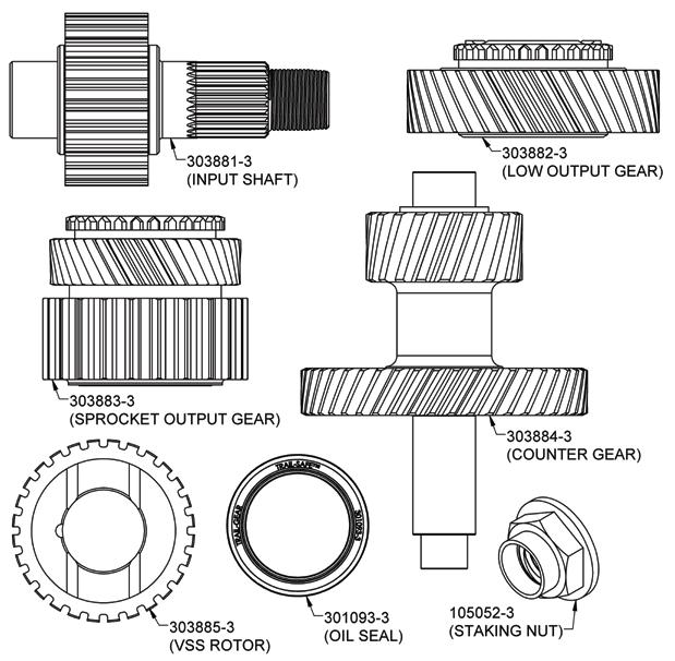
1 InstalL Instructions suzuki jimny electric/push-button transfer Case gears kit (17% High Range Reduction, 87% Low Range Reduction) kit contents INCLUDED NOTE: If your Jimny has an automatic transmission, you will need to replace your transfer case chain with Suzuki t-case chain P/N A00 (not included). Speedo gear is calibrated for [ mm] tire sizes. If you have a different tire size, your speedometer may not be accurate ins 5356 PINE AVE FRESNO, CA USA TOLL FREE: 877.4X4.TOYS WORLDWIDE:
2 recommended tools Safety Glasses Rubber Mallet Metric Ratchet & Socket Set Die Grinder or Angle Grinder Snap Ring Pliers Jack Stands Arbor Press Seal Puller Torque Wrench Wheel Bearing Grease Drain Pan Threadlocking Compound (Loctite 242 or equivalent) API GL4 SAE 75W-90 Gear Oil (Approximately 1.2 quarts/1.13 L) Pin or Alignment Punch (Suzuki P/N or equivalent) Ball Peen Hammer Flat Head Screwdriver Metric Wrench Set Floor Jack Transmission Jack Razor Blade or Gasket Scraper Seal/Bearing Driver Set Bearing Splitter Allen Wrench Set Drift Punch Degreasing Compound (e.g. Brake Cleaner) Large Adjustable Pin Wrench (Suzuki P/N or equivalent) Case Separator Tool (Suzuki P/N or equivalent) 5356 PINE AVE FRESNO, CA USA TOLL FREE: 877.4X4.TOYS WORLDWIDE:
.")

3 caution 1. Read all instructions completely and carefully before you begin. If anything is not clear, please call our tech support line at X4.TOYS or or before proceeding. 2. Check to make sure the kit is complete and that no parts are missing (refer to the Kit Contents Section on the first page of these instructions). If anything is missing, please contact Trail-Gear at X4.TOYS or or 3. Park vehicle on a clean, dry, flat, level surface and block the tires so the vehicle cannot roll in either direction. 4. This product is for off-road use only. It is recommended that the installation steps below be performed by a competent mechanic. Buyers and users of this product hereby expressly assume all risks associated with the installation and use of this product. 5. This installation is typical for most Suzuki Jimny vehicles. Some vehicles may vary. If necessary, refer to the proper Suzuki Factory Service Manual for the year and model of your vehicle. step 1 Press the 4WD switch to put the transfer case in 4WD high. The 4WD indicator light should be lit, and the 4WD Low indicator light should be off. step 2 Open the hood and disconnect the negative (-) terminal from the battery.

4 step 3 Lift up the front end of the vehicle with a floor jack and place jack stands under the front end on both sides of the frame. Repeat for the rear end of the vehicle. step 4 Place a drain pan underneath the transfer case. Remove the fill plug. Remove the drain plug and allow the transfer case to drain completely. Save both plugs for reinstallation. Discard the used oil in accordance with all local laws. Many auto parts stores will accept used oil for little or no cost. step 5 Remove the (4) driveline nuts & bolts from the rear transfer case drive flange and save for reinstallation. Suspend the driveline from the frame with a hook or stout wire to avoid putting strain on the driveline u-joint. Repeat for the front drivelines.
 connector. step 9 Place a transmission jack under the transfer case and use it to support the transfer case. Remove the (3) mounting nuts.")
5 step 6 Disconnect the 4WD switch connector (gray) and the 4WD low switch connector (white). step 7 Disconnect the transfer shift actuator motor connector and unclamp the harness. step 8 Disconnect the Vehicle Speed Sensor (VSS) connector. step 9 Place a transmission jack under the transfer case and use it to support the transfer case. Remove the (3) mounting nuts. Unbolt and remove the right-hand mounting bracket from the transfer case. Save the bracket and all hardware for reinstallation. step 10 Lower the transfer case. Unbolt and remove the left-hand mounting bracket from the transfer case. Save the bracket and all hardware for reinstallation. step 11 Remove the 4WD switch & 4WD Low switch from the transfer case. Using a magnetic removal tool, remove the (2) steel balls from the transfer case. Save the switches and steel balls for reinstallation.


 rear transfer case bolts. Save all parts for reinstallation.")

6 step 12 Remove the VSS from the transfer case. Save the VSS for reinstallation. step 13 Remove the rear drive flange staking nut using a large removable pin wrench to hold the flange in place. Remove the rear drive flange and save for reinstallation. Discard the staking nut. step 14 Remove the case cover and pinion gear. Then remove the transfer shift actuator. Save all parts for reinstallation. step 15 Remove the (11) rear transfer case bolts. Save all parts for reinstallation. step 16 Separate the front case from the rear case using a case separator. Alternatively, a large flat head screwdriver may be carefully used to separate the cases. step 17 Remove the VSS rotor and steel ball. Discard the stock VSS rotor. Save the steel ball for reinstallation. CASE SEPARATOR TOOL
 step 18 step 19 Remove the front drive flange staking nuts using a large adjustable pin wrench to hold")


7 InstalL Instructions (Cont'd.) step 18 step 19 Remove the front drive flange staking nuts using a large adjustable pin wrench to hold the flange in place. Remove the front drive flanges and save for reinstallation. Discard the staking nuts. Remove the drive chain, input shaft, and sprocket output gear. Discard the sprocket output gear. Retain all other parts for reinstallation. step 20 step 21 Remove the needle roller bearings and thrust bearing. Retain all parts for reinstallation. Remove the counter gear assembly from the front case. Retain all parts for reinstallation. step 22 step 23 Remove the rear output shaft assembly and both shift fork shafts. All (3) items must be removed together. Retain all parts for reinstallation. Remove the needle roller bearing and synchronizer ring from the front case. Retain all parts for reinstallation.

8 step 24 Remove the front output shaft assembly from the front case. Retain all parts for reinstallation. step 25 Remove the plug and pin from the front case. Retain all parts for reinstallation. step 26 Using a seal puller, remove both oil seals from the front case. Discard both oil seals. step 27 Using snap ring pliers, remove the bearing retention snap ring from the front case. Remove both bearings from the front case using a bearing removal tool and an arbor press. Retain the snap ring for reinstallation.


9 step 28 Using a die grinder or an angle grinder, clearance the gussets in the front case in the area between the oil protection plate and the oil receiver. After clearancing, the gussets should be almost completely removed as shown in the photograph below. Make sure to clean the case thoroughly after cutting to remove all metal chips and particles. step 29 Using a seal puller, remove the oil seal from the rear case. Discard the oil seal. step 30 Using snap ring pliers, remove the bearing retention snap ring from the rear case. Remove the bearing from the rear case using a bearing removal tool and an arbor press. Retain the snap ring for reinstallation.


10 step 31 Using a bearing puller, remove the bearing from the input shaft. Discard the input shaft and save the bearing for reinstallation. step 32 Using a bearing puller, remove the bearings from the counter gear. Discard the counter gear and save the bearings for reinstallation. step 33 Remove the clutch hub sleeve from the drive clutch hub gradually while holding down the steel balls in order to prevent the steel balls and springs from flying out. Using snap ring pliers, remove the snap ring from the rear output shaft. Save all components for reinstallation step 34 Press off the low output gear from the rear output shaft using a bearing splitter and an arbor press. step 35 Remove the low output gear and needle bearing from the rear output shaft. Discard the low output gear. Save all other components for reinstallation.

11 step 36 Using a razor blade, carefully remove the remaining gasket material from the flanges of both the front and rear cases. Clean the mounting flanges and the inside of both cases thoroughly with degreasing solvent. Make sure all metal particles and other debris are removed from both cases. step 37 Using a bearing installer, reinstall the (2) bearings removed in Step 27 into the front case. step 38 Using snap ring pliers, reinstall the snap ring removed in Step 27 into the front case. step 39 Using a seal installer, install (2) of the oil seals provided in this kit into the front case. Apply wheel bearing grease all around the sealing lips of both seals.


12 step 40 Using a bearing installer, reinstall the bearing removed in Step 30 into the rear case. step 41 Using snap ring pliers, reinstall the snap ring removed in Step 30 into the rear case. step 42 Using a seal installer, install the remaining oil seal provided in this kit into the rear case. Apply wheel bearing grease all around the sealing lips of the seal. step 43 Using an arbor press and bearing splitter, press-fit the input bearing removed in Step 31 onto the new input shaft provided in this kit. NOTE: Make sure to apply pressure to the inner race only. DO NOT apply pressure to any other part of the bearing, as it will damage the bearing. step 44 Using an arbor press and a bearing installation tool, press-fit the counter gear bearings removed in Step 32 onto the new counter gear provided in this kit. NOTE: Make sure to apply pressure to the inner race only. DO NOT apply pressure to any other part of the bearing, as it will damage the bearing.

13 step 45 Install the new low output gear provided in this kit and the needle bearing removed in Step 35 onto the rear output shaft. step 46 Press-fit the front drive clutch hub onto the rear output shaft using an arbor press and a bearing installation tool. Make sure to install the front drive clutch hub in the proper orientation as shown in the image below. Make sure to support the low output gear with the flat side of the bearing splitter to avoid damage to the gear teeth. step 47 Install the front drive clutch hub sleeve onto the front drive clutch hub, then reinstall the springs, steel balls, and keys removed in Step 33. Make sure to install the front drive clutch hub sleeve in the proper orientation as shown in the image below. Reinstall the snap ring using snap ring pliers. Make sure each gear moves smoothly after assembly. step 48 Reinstall the front output shaft into the front case. Install the front output flange onto the front output shaft. Apply threadlocking compound to the threads of (1) of the staking nuts and install onto the threads of the front output shaft. Using an adjustable pin wrench and a torque wrench, tighten the staking nut to 94 ft-lbs (130 N-m). Stake the nut onto the front output shaft using a drift punch and a ball peen hammer.
 step 49 step 50 Apply gear oil to the needle bearing and the synchronizer ring.")


14 InstalL Instructions (Cont'd.) step 49 step 50 Apply gear oil to the needle bearing and the synchronizer ring. Install both onto the front output shaft. Assemble the rear output shaft assembly, shift fork shaft assembly, and reduction clutch sleeve together. Make sure the clutch sleeve is installed in the proper orientation as shown below. Install them into the front case. Apply wheel bearing grease to the output shaft O-ring and install the O-ring onto the rear output shaft. step 51 step 52 Reinstall the counter gear assembly into the front case. Verify that the new counter gear does not hit the transfer case. If there is not enough clearance, go back to Step 28 and clearance as needed. step 53 Apply gear oil to the thrust bearing and needle roller bearing. Install them onto the rear output shaft as shown. Make sure to install the thrust bearing in the correct orientation as shown below. step 54 Install the input shaft assembly, chain, and the new sprocket gear provided in this kit onto the front case as a single assembly.


 of the staking nuts and install onto the threads of the rear output shaft.")
15 step 55 Reinstall the steel ball onto the rear output shaft. Install the new VSS rotor provided in this kit onto the rear output shaft. Make sure to align the slot in the VSS rotor with the steel ball. Make sure the VSS rotor will rotate with the rear output shaft. step 56 Make sure the mating surfaces of the both cases are still clean. Apply a bead of the RTV silicone included with this kit neatly and evenly on the mating surface of the front case. The bead should be about 0.05 (1.2mm) in diameter. step 57 Align the front and rear cases and assemble them together. Install the rear flange onto the rear output shaft. Apply blue Loctite to the threads of (1) of the staking nuts and install onto the threads of the rear output shaft. Using an adjustable pin wrench and a torque wrench, tighten the staking nut to 94 ft-lbs (130 N-m). Stake the nut onto the rear output shaft using a drift punch and a ball peen hammer.


16 step 58 Reinstall the transfer case bolts. Note the location of the long and short bolts. Torque each bolt to 13 ft-lbs (18 N-m). step 59 Set the No. 2 shift fork in the 4H position by pushing it in the direction shown. step 60 Insert a drift or alignment punch into the hole in the transfer case to hold shift fork shaft No. 1 in place. Move the shaft in the directions shown below while pushing on the punch to find the hole in the shaft. step 61 Make sure the transfer shift actuator is in the 4H position. Reinstall the transfer shift actuator onto the transfer case. Reinstall the pinion gear. Clean the mating surfaces of the shift actuator and the case cover with a degreasing solvent. Apply a bead of the RTV silicone included with this kit neatly and evenly on the mating surface of the case cover. The bead should be about 0.05 (1.2mm) in diameter. Reinstall the (3) case cover bolts and tighten the bolts to 14.5 ft-lbs (20 N-m).
17 step 62 Remove the alignment punch from the transfer case. Reinstall the straight pin and the straight pin plug. Torque the straight pin plug to 18 ft-lbs (25 N-m). step 63 Reinstall the VSS onto the transfer case. Torque the bolts to 3.5 ft-lbs (5 N-m). step 64 Install the front input flange onto the transfer case. Apply blue Loctite to the threads of the remaining staking nut and install onto the threads of the front input shaft. Using an adjustable pin wrench and a torque wrench, tighten the staking nut to 94 ft-lbs (130 N-m). Stake the nut onto the front input shaft using a drift punch and a ball peen hammer. step 65 Reinstall the steel balls into the transfer case, then reinstall the 4WD switch and the 4WD low switch. Torque both switches to 14 ft-lbs (19 N-m). step 66 Reinstall the left-hand mounting bracket and the (4) mounting bolts onto the transfer case. Torque each bolt to 17 ft-lbs (23 N-m).
 nuts removed in Step 9. Torque each nut to 22 ft-lbs (30 N-m). step 68 Plug the VSS connector onto the VSS.")
18 step 67 Place the transfer case on a transmission jack. Reinstall the right-hand mounting bracket and the (4) mounting bolts onto the transfer case. Torque each bolt to 17 ft-lbs (23 N-m). Mount the transfer case to the vehicle using the (3) nuts removed in Step 9. Torque each nut to 22 ft-lbs (30 N-m). step 68 Plug the VSS connector onto the VSS. step 69 Reconnect the 4WD switch connector (gray) and the 4WD low switch connector (white). step 70 Clamp the transfer shift actuator motor harness onto the transfer case. Reconnect the transfer case actuator connector to the transfer shift actuator motor. step 71 Reinstall the drain plug and torque to 17 ft-lbs (23 N-m). Fill the transfer case with API GL-4 75W-90 gear oil or the gear oil recommended in your Owner s Manual. Fill the transfer case until the oil level reaches the bottom of the oil fill plug hole. Reinstall the fill plug and torque to 17 ft-lbs (23 N-m).
 terminal to the battery and close the hood. step 74 Lower the vehicle. Verify all bolts have been reinstalled and torqued.")
19 step 72 Reinstall the rear driveline to the rear output flange using the nuts and bolts removed in Step 5. Torque to 36.5 ft-lbs (50 N-m). Repeat for the front drivelines. step 73 Reconnect the negative (-) terminal to the battery and close the hood. step 74 Lower the vehicle. Verify all bolts have been reinstalled and torqued. Verify all wiring plugs have been reconnected. Take the vehicle for a short test drive and verify shift lights and speedometer function. After the transfer case cools, recheck the gear oil level and add gear oil if needed. After the first 10 miles of driving, recheck the gear oil level and top off as needed. maintenance Change the gear oil after the first 1,000 miles or after the first trail ride, whichever comes first. After the initial oil change, change the gear oil once a year or every 10,000 miles, whichever comes first. Check the gear oil level every time the engine oil is changed. Also check the gear oil level whenever the vehicle rolls over, as gear oil may leak out.

20 replacement parts
InstalL Instructions. trail-creeper Ring & Pinion Gears Installation Instructions. kit contents. recommended tools ins
 InstalL Instructions trail-creeper Ring & Pinion Gears Installation Instructions kit contents recommended tools Safety Glasses Torque Wrench Metric Ratchet & Socket Set Drain Pan Metric Wrench Set Arbor
InstalL Instructions. trail-creeper 4.70 transfer case gear kit ( KIT and KIT) kit contents
 kit contents") InstalL Instructions trail-creeper 4.70 transfer case gear kit (105000-1-KIT and 105001-1-KIT) kit contents 5356 PINE AVE FRESNO, CA 93727 USA TOLL FREE: 877.4X4.TOYS WORLDWIDE: 559.252.4950 WWW.TRAIL-GEAR.COM
InstalL Instructions trail-creeper 4.70 transfer case gear kit (105000-1-KIT and 105001-1-KIT) kit contents 5356 PINE AVE FRESNO, CA 93727 USA TOLL FREE: 877.4X4.TOYS WORLDWIDE: 559.252.4950 WWW.TRAIL-GEAR.COM
kit contents trail-safe samurai inner axle seal suzuki samurai (all engines) InstalLation Instructions
 InstalLation Instructions") InstalLation Instructions trail-safe samurai inner axle seal 300748-3-kit 1986-1995 suzuki samurai (all engines) kit contents 5356 PINE AVE FRESNO, CA 93727 USA TOLL FREE: 877.4X4.TOYS WORLDWIDE: 559.252.4950
InstalLation Instructions trail-safe samurai inner axle seal 300748-3-kit 1986-1995 suzuki samurai (all engines) kit contents 5356 PINE AVE FRESNO, CA 93727 USA TOLL FREE: 877.4X4.TOYS WORLDWIDE: 559.252.4950
InstalLation Instructions
 InstalLation Instructions Trail-Creeper tacoma dual transfer case adapter Kit 107530-1-kit 107531-1-kit Kit Contents 111111111262525- (1995-2004 toyota tacoma 4wd, 2.7L manual) (1995-2004 toyota tacoma
InstalL Instructions. fj40 knuckle conversion kit. kit contents
 InstalL Instructions fj40 knuckle conversion kit 1960-1983 toyota fj40 1960-1983 toyota fj45 304149-1-kit 304150-1-kit 304151-1-kit 304152-1-kit 304153-1-kit 304154-1-kit 304155-1-kit 304156-1-kit 304157-1-kit
InstalL Instructions. trail-safe nissan patrol y60 knuckle wiper seal kit. kit contents ins
 InstalL Instructions trail-safe nissan patrol y60 knuckle wiper seal kit 303920-kit Nissan Patrol GR (Y60) 1987-1997 (All Engines) Nissan Patrol GQ 1987-1997 (All Engines) Nissan Patrol Safari 1987-1997
InstalLation Instructions
 Trail-Creeper tacoma dual transfer case adapter Kit 107523-1-KIT Kit Contents 111111111262525- Coupler Adapter Plate w/bearings installed Bearing Spacer Snap Ring Washer, Flat M10 Washer, Lock M10 Washer,
Suzuki Samurai 6.5 Transfer Case Gear Kit, KIT
 Suzuki Samurai 6.5 Transfer Case Gear Kit, 105004-3-KIT Kit Contents: Gear, 26 Spline/26 Tooth 1.0 Gear, 44 Tooth 1.0 Gear, 58 Tooth/23 Tooth 1.0 Gear, 67 Tooth/ 27 Tooth 1.0 Counter Shaft 1.0 Counter
high-steer kit for toyota solid front axles installation instructions
 InstalL Instructions high-steer kit for toyota solid front axles installation instructions kit contents high steer kit for toyota solid front axles on toyota vehicles high steer kit for toyota oem solid
nissan patrol birfield kit
 nissan patrol birfield kit 300795-kit 1987-1997 nissan patrol gr(y60) 1988-1994 ford maverick 1987-1997 nissan patrol gq 1987-1997 nissan patrol safari 1987-1997 nissan safari kit contents 5356 PINE AVE
InstalLation Instructions. rock ripper tacoma 2.7l header tacoma/4runner header, 2.7l ( KIT) kit contents
 kit contents") InstalLation Instructions rock ripper tacoma 2.7l header tm 95-98 tacoma/4runner header, 2.7l (180308-1-KIT) kit contents 5356 EAST PINE AVE FRESNO, CA 93727 USA TOLL FREE: 877.4X4.TOYS WORLDWIDE: 559.252.4950
InstalLation Instructions rock ripper tacoma 2.7l header tm 95-98 tacoma/4runner header, 2.7l (180308-1-KIT) kit contents 5356 EAST PINE AVE FRESNO, CA 93727 USA TOLL FREE: 877.4X4.TOYS WORLDWIDE: 559.252.4950
InstalL Instructions. rear disc brake kit Kit ( toyota pickup/4runner) 2 ct. Brake rotors. 2 ct. 2 ct. Adapter Rings. 2 ct.
 2 ct. Brake rotors. 2 ct. 2 ct. Adapter Rings. 2 ct.") InstalL Instructions rear disc brake kit 140250-1-Kit (1979-1995 toyota pickup/4runner) kit contents Brake rotors Brake calipers Adapter Rings (1) Long brake line (1) Short brake line Brackets 8 ct. (6)
InstalL Instructions rear disc brake kit 140250-1-Kit (1979-1995 toyota pickup/4runner) kit contents Brake rotors Brake calipers Adapter Rings (1) Long brake line (1) Short brake line Brackets 8 ct. (6)
3. Park vehicle on a clean, dry, flat, level surface and block the tires so the vehicle cannot roll in either direction.
 InstalL Instructions ram assist single-ended ram rebuild kit 304201-kit 304202-kit (for 1.5" bore x 3/4" rod rams with 6" or 8" stroke) (for 2" bore x 3/4" rod rams with 6" or 8" stroke) kit contents 304202-ins
Trail-Creeper Dual Transfer Case Adapter
 Trail-Creeper Dual Transfer Case Adapter Installation Instructions For Kits: 100001-1-KIT 21 Spline 100006-1-KIT 23 Spline KIT Contents: 23 or 21 Spline Coupler 1.0 Adapter Plate w/ Bearings Installed
kit contents tacoma front 3" spacer lift kit InstalLation Instructions kit ( tacoma prerunner/4wd, Runner 4wd)
") tacoma front 3" spacer lift kit 300599-1-kit (1995-2013 tacoma prerunner/4wd, 1996-2012 4Runner 4wd) kit contents 5356 PINE AVE FRESNO, CA 93727 USA TOLL FREE: 877.4X4.TOYS WORLDWIDE: 559.252.4950 WWW.TRAIL-GEAR.COM
tacoma front 3" spacer lift kit 300599-1-kit (1995-2013 tacoma prerunner/4wd, 1996-2012 4Runner 4wd) kit contents 5356 PINE AVE FRESNO, CA 93727 USA TOLL FREE: 877.4X4.TOYS WORLDWIDE: 559.252.4950 WWW.TRAIL-GEAR.COM
LIMITED SLIP DIFFERENTIAL INSTALLATION
 Installation of the limited slip gear can be done with axle out of car or with car lifted to gain access from underneath. Refer to repair manual for proper lifting instructions if car is to be lifted.
Toyota V6 Adapter Plate, KIT
 Toyota V6 Adapter Plate, 100086-1-KIT KIT Contents: 100086-1 Dual Adapter, V6 88-95 1.0 100088-1 Coupler, V6 23S-23S 1.0 100089-1 Bolt, M10-1.25x35 6.0 100091-1 Bolt, M10-1.25x30 Flat Head Allen Bolt 2.0
InstalL Instructions. kit contents ins
 InstalL Instructions duraline & duraline exoshield winch lines 303417 (3/8 x 75 DuraLine ExoShield ) 303418 (3/8 x 100 DuraLine ExoShield ) 303827 (3/8 x 125 DuraLine ExoShield ) 303828 (3/8 x 150 DuraLine
2 ct. Brake rotors. 2 ct. Freeze plugs. 2 ct. 2 ct. 8 ct. (6) M10x1.5x40 Bolts (2) M10x1.5x35 Bolts M10x1.5 Toplock Nuts. 2 ct. Brackets ( K)
 M10x1.5x40 Bolts (2) M10x1.5x35 Bolts M10x1.5 Toplock Nuts. 2 ct. Brackets ( K)") InstalL Instructions tacoma rear disc brake kit (144039-1-K) kit contents Brake rotors Brake calipers Freeze plugs (1) Long brake line (1) Short brake line Brackets 8 ct. (6) M10x1.5x40 Bolts (2) M10x1.5x35
InstalL Instructions tacoma rear disc brake kit (144039-1-K) kit contents Brake rotors Brake calipers Freeze plugs (1) Long brake line (1) Short brake line Brackets 8 ct. (6) M10x1.5x40 Bolts (2) M10x1.5x35
REMOVAL TF REMOVE TRANSFER INDICATOR SWITCH (a) Remove the switches and gaskets. HINT: Indicator switch:
 Remove the switches and gaskets. HINT: Indicator switch:") 20 NO. 1 NO. 2 F043499 REMOVAL 1. DISCONNECT CABLE FROM NEGATIVE BATTERY TERMINAL CAUTION: Wait at least 90 seconds after disconnecting the cable from the negative (-) battery terminal to prevent airbag
20 NO. 1 NO. 2 F043499 REMOVAL 1. DISCONNECT CABLE FROM NEGATIVE BATTERY TERMINAL CAUTION: Wait at least 90 seconds after disconnecting the cable from the negative (-) battery terminal to prevent airbag
MARLIN CRAWLER FRONT CHROMOLY OUTPUT SHAFT
 F r o n t C h r o m o l y O u t p u t 1 MARLIN CRAWLER FRONT CHROMOLY OUTPUT SHAFT FOREWORD This Installer shows how to install our 30-spline Front Chromoly Output Shaft into a Toyota 1979-95 gear drive
2 ct. Brake rotors. 2 ct. 8 ct. (6) M10x1.5x40 Bolts (2) M10x1.5x35 Bolts M10x1.5 Toplock Nuts. 2 ct. 2 ct. Brackets ( K) Brake calipers
 M10x1.5x40 Bolts (2) M10x1.5x35 Bolts M10x1.5 Toplock Nuts. 2 ct. 2 ct. Brackets ( K) Brake calipers") InstalL Instructions rear disc brake kit (140250-1-K) kit contents Brake rotors Brake calipers (1) Long brake line (1) Short brake line Brackets 8 ct. (6) M10x1.5x40 Bolts (2) M10x1.5x35 Bolts M10x1.5
InstalL Instructions rear disc brake kit (140250-1-K) kit contents Brake rotors Brake calipers (1) Long brake line (1) Short brake line Brackets 8 ct. (6) M10x1.5x40 Bolts (2) M10x1.5x35 Bolts M10x1.5
InstalL Instructions. rock defense jeep yj roll cage kit. kit contents ins
 InstalL Instructions rock defense jeep yj roll cage 300152-2-kit kit contents tube identification 300102-2 Passenger Roof Tube (Qty: 1) 300103-2 Driver Roof Tube (Qty: 1) 300104-2 Windshield Tube (Qty:
Installation Instructions
 Instructions Created by an: Inchworm Gear Clockable Toyota Dual Transfer Case Adapter Kit, 21 or 23 Spline SKU# TCASE-IW-300-000 Installation Instructions CAUTION: Safety glasses should be worn at all
InstalLation Instructions
 creeper locks 8-lug kit contents: 5356 PINE AVE FRESNO, CA 93727 USA TOLL FREE: 877.4X4.TOYS WORLDWIDE: 559.252.4950 WWW.TRAIL-GEAR.COM recommended tools Ratchet & Socket Set 5-Gallon Bucket Thin Wall
81-87, 22r/re 4wd, 50 state smog legal header ( k) r 4wd ca only 50 state smog legal header ( k) 1 ct.
 r 4wd ca only 50 state smog legal header ( k) 1 ct.") InstalLation Instructions rock ripper toy header tm 81-87, 22r/re 4wd, 50 state smog legal header (180302-1-k) 81-84 22r 4wd ca only 50 state smog legal header (180303-1-k) kit contents Header Tube Intermediate
InstalLation Instructions rock ripper toy header tm 81-87, 22r/re 4wd, 50 state smog legal header (180302-1-k) 81-84 22r 4wd ca only 50 state smog legal header (180303-1-k) kit contents Header Tube Intermediate
Installation Instructions
 Instructions Created by an: Inchworm Tacoma Dual Case Adapter Installation Instructions Suggested Tools: CAUTION: Safety glasses should be worn at all times when working with vehicles and related tools
1 ct. 1 ct. 2 ct. 2 ct. 1 ct. 2 ct. 1 ct. 2 ct. 2 ct. 2 ct. Air Injection Tube Gaskets. 1 ct. 4 ct. 4 ct. 1 ct. 2 ct. 2 ct.
 rock ripper tm toy header 88-95 4cyl, 4wd, 50 state smog legal header - 180304-1-k kit contents Header Tube Intermediate Tube Flanges Header Flange Gaskets Exhaust Clamps Header Gasket CARB Decal Air Injection
InstalLation Instructions
 creeper locks for hub centric vechiles kit contents: 5356 PINE AVE FRESNO, CA 93727 USA TOLL FREE: 877.4X4.TOYS WORLDWIDE: 559.252.4950 WWW.TRAIL-GEAR.COM recommended tools Ratchet & Socket Set 5-Gallon
1 ct. 2 ct. 1 ct. 1 ct. 2 ct. 2 ct. 2 ct. 1 ct. 2 ct. 4 ct. 4 ct. 1 ct. 2 ct. 8 ct. 2 ct , k 85-95, k. Header Tube.
 rock ripper tm toy header 79-84, 186053-1-k 85-95, 186063-1-k kit contents Header Tube Intermediate Tube Flanges Header Flange Gaskets Exhaust Clamps 5 ft. 16g Wire Wire Connectors Header Gasket Air Injection
Installation Instructions
 ) Instructions Created by an: Suzuki Sidekick / Tracker "Game Changer" 4 Speed Auto to Toyota T-Case Adapter Kit (SKU# KTC-GC-21, KTC-GC-23) Installation Instructions Suggested Tools: CAUTION: Safety glasses
ADVANCE ADAPTERS INC. Fixed Yoke kit (S.Y.E. Kit)
") ADVANCE ADAPTERS INC. Fixed Yoke kit (S.Y.E. Kit) Instruction Sheet P/N: 50-7905 & 50-7906 KIT CONSISTS OF: No. Qty Part No. Description 1. 1 51-7906 TAILHOUSING, DIECAST 2. 1 52-7905 SHAFT, MAIN OUTPUT
ADVANCE ADAPTERS INC. Fixed Yoke kit (S.Y.E. Kit) Instruction Sheet P/N: 50-7905 & 50-7906 KIT CONSISTS OF: No. Qty Part No. Description 1. 1 51-7906 TAILHOUSING, DIECAST 2. 1 52-7905 SHAFT, MAIN OUTPUT
1. General Description
 1. General Description A: SPECIFICATION 1. MANUAL TRANSMISSION AND FRONT DIFFERENTIAL Type Transmission gear ratio Front reduction gear Rear reduction gear Front differential Center differential Final
MANUAL TRANSMISSION SECTIONMT CONTENTS IDX FS5W71C. ASSEMBLY...24 Gear Components...24
 MANUAL TRANSMISSION SECTIONMT GI MA EM LC EC CONTENTS FE FS5W71C PREPARATION...3 Special Service Tools...3 Commercial Service Tools...5 NOISE, VIBRATION AND HARSHNESS (NVH) TROUBLESHOOTING...6 NVH Troubleshooting
EG1 485 OIL PUMP COMPONENTS FOR REMOVAL AND INSTALLATION
 EG1485 OIL PUMP COMPONENTS FOR REMOVAL AND INSTALLATION EG1486 EG1487 EG1488 OIL PUMP REMOVAL (See Components for Removal and Installation) HINT: When repairing the oil pump, the oil pan an^ strainer should
TRANSMISSION AND TRANSFER CASE
 XJ TRANSMISSION AND TRANSFER CASE 21-1 TRANSMISSION AND TRANSFER CASE TABLE OF CONTENTS page AX5 MANUAL TRANSMISSION... 1 NV3550 MANUAL TRANSMISSION... 42 AUTOMATIC TRANSMISSION 30RH... 88 page AW 4 AUTOMATIC
MANUAL TRANSMISSION SECTIONMT CONTENTS IDX FS5W71C. Case Components...27
 MANUAL TRANSMISSION SECTIONMT GI MA EM LC EC CONTENTS FE FS5W71C PREPARATION...3 Special Service Tools...3 Commercial Service Tools...5 NOISE, VIBRATION AND HARSHNESS (NVH) TROUBLESHOOTING...6 NVH Troubleshooting
InstalL Instructions. jeep yj roll cage kit. kit contents
 InstalL Instructions jeep yj roll cage 300152-2-kit kit contents tube identification 300102-2 300103-2 300104-2 300105-2 300106-2 300107-2 Driver A to B pillar (Qty: 1) Passenger A to B pillar (Qty: 1)
Installation Instructions
 Instructions Created by an: 86-95 Suzuki Samurai Samurai Front Axle Knuckle Rebuild Kits (SKU# SAX-KRK) Installation Instructions Revised 6-6-14 Suggested Tools: CAUTION: Safety glasses should be worn
TRANSFER CASE Mitsubishi Montero APPLICATION DESCRIPTION TESTING 4WD INDICATOR CONTROL UNIT (MONTERO) DETECTION SWITCH
 DETECTION SWITCH") TRANSFER CASE 1993 Mitsubishi Montero 1991-94 TRANSFER CASES Mitsubishi Dodge; Ram-50 Mitsubishi; Pickup, Montero APPLICATION TRANSFER CASE APPLICATIONS TABLE Application (1) Transmission Model Dodge 1991-93
TRANSFER CASE 1993 Mitsubishi Montero 1991-94 TRANSFER CASES Mitsubishi Dodge; Ram-50 Mitsubishi; Pickup, Montero APPLICATION TRANSFER CASE APPLICATIONS TABLE Application (1) Transmission Model Dodge 1991-93
ATTENTION ADVANCE SERVICE BULLETIN INFORMATION
 SUBJECT: NO: 21-10-98 Loss Of Fifth Gear GROUP: Transmission EFFECTIVE DATE: Sep. 11, 1998 CHRYSLER MAIL MANAGEMENT SYSTEM DATE: AUG. 28, 1998 ATTENTION ADVANCE SERVICE BULLETIN INFORMATION The following
InstalLation Instructions. Rock Assault hydro assist ram kit. kit contents
 InstalLation Instructions Rock Assault hydro assist ram kit 130250-1-kit (1.5" x 6") 130251-1-KIT (2" x 6") 130266-1-KIT (2" x 8") 130056-1-kit (1.5" x 6" Rock Assault) 130058-1-kit (2" x 8" Rock Assault)
ADVANCE ADAPTERS INC. P/N: NP231 SHORT SHAFT "FIXED YOKE" KIT
 Paso Robles, CA 93447 PAGE 1 OF 10 Telephone: (800) 350-2223 Fax: (805) 238-4201 Page Rev. Date: 06-24-02 KIT CONSISTS OF: No. Qty Part No. Description 1. 1 51-7906 TAILHOUSING, DIECAST 2. 1 52-7905 SHAFT,
MANUAL TRANSAXLE Return to Main Table of Contents
 MANUAL TRANSAXLE Return to Main Table of Contents GENERAL... 2 MANUAL TRANSAXLE CONTROL... 12 SHIFT LEVER ASSEMBLY... 14 MANUAL TRANSAXLE... 15 MANUAL TRANSAXLE ASSEMBLY... 17 FIFTH SPEED SYNCHRONIZER
2001 Dodge RAM 3500 PICKUP
 1 of 76 9/14/2012 7:02 PM 2001 Dodge RAM 3500 PICKUP Submodel: Engine Type: L6 Liters: 5.9 Fuel Delivery: FI Fuel: DIESEL Subarticles MANUAL- NV3500 - DISASSEMBLY MANUAL- NV3500 - DISASSEMBLY MANUAL -
NP231 SHORT SHAFT "FIXED YOKE" KIT
 Page 1 of 11 KIT CONSISTS OF: No. Qty Part No. Description 1. 1 51-7905 TAILHOUSING, DIECAST 2. 1 52-7905 SHAFT, MAIN OUTPUT 3. 1 300474 SEAL WASHER, REAR YOKE 4 1 300475 YOKE, C.V. REAR 5. 1 300476 NUT,
DRIVE AXLE - INTEGRAL HOUSING
 DRIVE AXLE - INTEGRAL HOUSING 1993 Toyota Celica 1993 DRIVE AXLES Toyota Differentials & Axle Shafts - Integral Housing Toyota; Celica All-Trac DESCRIPTION Drive axle assembly is a hypoid type with integral
DRIVE AXLE Nissan 240SX DESCRIPTION & OPERATION AXLE RATIO & IDENTIFICATION AXLE SHAFT & BEARING R & I DRIVE SHAFT R & I
 DRIVE AXLE 1990 Nissan 240SX 1990 DRIVE AXLES Rear Axle - R200 240SX, 300ZX DESCRIPTION & OPERATION The axle assembly is a hypoid type gear with integral carrier housing. The pinion bearing preload adjustment
SUZUKI SQ 416/420/625 M.Y TRANSMISSION SERVICE MANUAL - MANUAL - AUTOMATIC - TRANSFER - DIFFERENTIALS
 SUZUKI SQ 416/420/625 M.Y 1998-2005 TRANSMISSION SERVICE MANUAL - MANUAL - AUTOMATIC - TRANSFER - DIFFERENTIALS WARNING/CAUTION/NOTE IMPORTANT Please read this manual and follow its instructions carefully.
C3 Syncro Drive Proclimb 1100 Installation Instructions
 Revision 4 Nov 8-2013 201A Old Town Road, Sicamous, BC. V0E 2V4 Ph 250-833 3538 Fax 888-716 5903 www.c3powersports.com Thank you for purchasing a ProClimb M, ProCross F & XF SyncroDrive Note: This modification
Installation Instructions for the Tera low range Dana 20 (LOW20)
") Installation Instructions for the Tera low range Dana 20 (LOW20) Tera Manufacturing, Inc. 5251 South Commerce Dr. Murray, Utah 84107 Phone/801.288.2585 Fax/801.288.2571 www.teraflex.biz Attention: Verify
Installation Instructions for the Tera low range Dana 20 (LOW20) Tera Manufacturing, Inc. 5251 South Commerce Dr. Murray, Utah 84107 Phone/801.288.2585 Fax/801.288.2571 www.teraflex.biz Attention: Verify
Max IV Rear Axle Replacement For models after Serial Number and all rear splined axle replacements.
 Max IV Rear Axle Replacement For models after Serial Number 19089 and all rear splined axle replacements. 10/8/03 Max IV Snap Ring Rear Axle replacement.doc Tools required: 9/16 Wrench 6 Extension Steel
1988 Chevrolet Pickup V SUSPENSION - FRONT (4WD)' 'Front Suspension - "V" Series 1988 SUSPENSION - FRONT (4WD) Front Suspension - "V" Series
' 'Front Suspension - V Series 1988 SUSPENSION - FRONT (4WD) Front Suspension - V Series") 1988 SUSPENSION - FRONT (4WD) Front Suspension - "V" Series DESCRIPTION NOTE: Vehicle serial numbers used in this article has been abbreviated for common reference to Chevrolet and GMC models. Chevrolet
1988 SUSPENSION - FRONT (4WD) Front Suspension - "V" Series DESCRIPTION NOTE: Vehicle serial numbers used in this article has been abbreviated for common reference to Chevrolet and GMC models. Chevrolet
MANUAL TRANSMISSION MUA 5C (4X2, 4X4) AND TREMEC T5R(4X2)
 AND TREMEC T5R(4X2)") MANUAL TRANSMISSION 7B 1 RODEO TRANSMISSION MANUAL TRANSMISSION MUA 5C (4X2, 4X4) AND TREMEC T5R(4X2) CONTENTS Service Precaution...................... 7B 2 General Description..................... 7B
MANUAL TRANSMISSION 7B 1 RODEO TRANSMISSION MANUAL TRANSMISSION MUA 5C (4X2, 4X4) AND TREMEC T5R(4X2) CONTENTS Service Precaution...................... 7B 2 General Description..................... 7B
MANUAL GEAR HOUSING (4WD)
") SR26 STEERING MANUAL GEAR HOUSING (4WD) REMOVAL AND INSTALLATION OF MANUAL GEAR HOUSING Remove and install the parts as shown. (MAIN POINTS OF REMOVAL AND INSTALLATION) 1. DISCONNECT UNIVERSAL JOINT (a)
SR26 STEERING MANUAL GEAR HOUSING (4WD) REMOVAL AND INSTALLATION OF MANUAL GEAR HOUSING Remove and install the parts as shown. (MAIN POINTS OF REMOVAL AND INSTALLATION) 1. DISCONNECT UNIVERSAL JOINT (a)
RUBICRAWLER - JEEP TJ & JK ( ) W/ UNIVERSAL SHIFTER KIT CONSISTS OF: No. Qty Part No. Description
 W/ UNIVERSAL SHIFTER KIT CONSISTS OF: No. Qty Part No. Description") KIT CONSISTS OF: No. Qty Part No. Description 1. 1 RUBICRAWLER - GEAR BOX 2. 1 42R-UNIV - UNIVERSAL SHIFTER KIT PAGE 1 OF 8 Page Rev. Date: 11-06-18 Optional Items: Part No. Description 15-1000 - UNI-RAISE,
KIT CONSISTS OF: No. Qty Part No. Description 1. 1 RUBICRAWLER - GEAR BOX 2. 1 42R-UNIV - UNIVERSAL SHIFTER KIT PAGE 1 OF 8 Page Rev. Date: 11-06-18 Optional Items: Part No. Description 15-1000 - UNI-RAISE,
INSTALLATION INSTRUCTIONS
 INSTALLATION INSTRUCTIONS --1075 North Ave. Sanger, CA 93657-3539 local: 559-875-0222 fax: 559-876-2259 toll free: 800-445-3767-- 2505 Lowering Spindle Assembly Installation Instructions ½ TON SILVERADO
Swing Drive SMCS ;
 Unfiled Notes Page 1 Service Information System Friday, May 06, 2016 8:43 AM Disassembly and Assembly E110B EXCAVATOR VEHICLE SYSTEMS Media Number -SENR4576-01 Publication Date -01/06/2005 Date Updated
2005 Toyota Truck RAV4 2WD L4 2.4L (2AZ FE)
") 2005 Toyota Truck RAV4 2WD L4 2.4L (2AZ FE) Vehicle» Engine, Cooling and Exhaust» Engine» Timing Chain» Service and Repair TIMING CHAIN TIMING CHAIN http://alldatapro.com/alldata/pro~v440713400~c39519~r0~od~n/0/108596970/110859775/110859788/110859790/34853741/100411974/34853743/56492475
2005 Toyota Truck RAV4 2WD L4 2.4L (2AZ FE) Vehicle» Engine, Cooling and Exhaust» Engine» Timing Chain» Service and Repair TIMING CHAIN TIMING CHAIN http://alldatapro.com/alldata/pro~v440713400~c39519~r0~od~n/0/108596970/110859775/110859788/110859790/34853741/100411974/34853743/56492475
1. General Description
 1. General Description A: SPECIFICATIONS 1. Type Transmission gear ratio Front reduction gear Rear reduction gear 2. TRANSMISSION GEAR OIL Recommended oil Final Transfer 5-forward speeds with synchromesh
'99-03 CHEVROLET/GMC IFS 4WD 6" SUSPENSION SYSTEM P/N INSTALLATION INSTRUCTIONS
 1/16/04 '99-03 CHEVROLET/GMC IFS 4WD 6" SUSPENSION SYSTEM P/N. 10-41099 INSTALLATION INSTRUCTIONS NOTE: Each Lift Kit and options to Lift Kits are packaged separately. Therefore, installation procedures
INSTALLATION INSTRUCTIONS
 INSTALLATION INSTRUCTIONS ----1075 North Ave. Sanger, CA 93657-3539 toll free: 800-445-3767 web: www.belltechcorp.com---- 6419 HANGER & SHACKLE KIT FORD F-150 Congratulations! You were selective enough
Zoom and Print Options
 1 of 63 8/26/2017, 7:04 AM Vehicle» Transmission and Drivetrain» Transfer Case» Service and Repair» Procedures» Isuzu T150» Overhaul (Unit Repair)» 1. Transfer Case Disassemble Transfer Case Disassemble
NP231 SHORT SHAFT "FIXED YOKE" KIT FOR NON-CV YOKES AND FLANGE YOKES
 KIT CONSISTS OF: No. Qty Part No. Description 1. 1 51-7906 TAILHOUSING, DIECAST 2. 1 52-7905 SHAFT, MAIN OUTPUT 3. 1 300474 SEAL WASHER, REAR YOKE 4. 1 300476 NUT, REAR YOKE 5. 1 300480 SEAL WASHER, FRONT
DF 15. DIFFERENTIAL 1GR-FE FRONT DIFFERENTIAL CARRIER ASSEMBLY (for 4WD) REMOVAL
 REMOVAL") DIFFERENTIAL 1GR-FE FRONT DIFFERENTIAL CARRIER ASSEMBLY (for 4WD) 15 REMOVAL 1. REMOVE FRONT WHEELS 2. REMOVE REAR ENGINE UNDER COVER ASSEMBLY (a) Remove the 6 bolts and engine under cover assembly. 3.
DIFFERENTIAL 1GR-FE FRONT DIFFERENTIAL CARRIER ASSEMBLY (for 4WD) 15 REMOVAL 1. REMOVE FRONT WHEELS 2. REMOVE REAR ENGINE UNDER COVER ASSEMBLY (a) Remove the 6 bolts and engine under cover assembly. 3.
2005 Toyota RAV AUTOMATIC TRANSMISSIONS U240E & U241E Overhaul
 2001-05 AUTOMATIC TRANSMISSIONS U240E & U241E Overhaul APPLICATION CAUTION: Flush oil cooler and oil cooler lines prior to transaxle installation. Oil cooling system contamination may cause premature transaxle
1984 Dodge W250 PICKUP
 1984 Dodge W250 PICKUP Submodel: Engine Type: V8 Liters: 5.2 Fuel Delivery: CARB Fuel: GAS Dana 44 MODELS THROUGH 1984 2. Raise and safely support the vehicle, then remove the wheel hub and bearings as
INSTALLATION INSTRUCTIONS
 INSTALLATION INSTRUCTIONS 2102 LOWERING SPINDLE ASSEMBLY 1998-UP CHEVROLET / GMC BLAZER / X-TREME / JIMMY / ENVOY 2 Wheel Drive Congratulations! You were selective enough to choose a BELLTECH PRODUCT.
UOW Series Repair Manual UOW-11 & UOW-T60 Series
 UOW Series Repair Manual UOW-11 & UOW-T60 Series 100000 SE Pine St., Portland, OR 97216 800-852-1368 503-254-6600 www.aimco-global.com Contents Page 1. Tools Needed for Repair 2 2. Disassembly and Reassembly
INSTALLATION INSTRUCTION 88146
 INSTALLATION INSTRUCTION 88146 Rev H FOR RANCHO SUSPENSION SYSTEM RS6547: 4WD SUBURBAN/YUKON XL, 4WD TAHOE/YUKON, & 4WD AVALANCHE READ ALL INSTRUCTIONS THOROUGHLY FROM START TO FINISH BEFORE BEGINNING
Rear End Installation and Bearing Kit - 8.8in (86-12 V8; V6)
") Rear End Installation and Bearing Kit - 8.8in (86-12 V8; 11-13 V6) Tools Required: Jack Stands 5 Floor Jack 2 Oil Pans 1 Wheel Blocks 2 Differential Oil 3 qts Friction Modifier 3 bottles Tube of Black
Rear End Installation and Bearing Kit - 8.8in (86-12 V8; 11-13 V6) Tools Required: Jack Stands 5 Floor Jack 2 Oil Pans 1 Wheel Blocks 2 Differential Oil 3 qts Friction Modifier 3 bottles Tube of Black
Mustang Differential Gears - Installation Instructions
 Mustang Differential Gears - Installation Instructions The below installation instructions work for the following products: Ford Racing Gears - 3.73 Gears for 8.8" Ford Rear End Ford Racing Gears - FRPP
RUBICRAWLER - JEEP TJ & JK ( ) W/ UNIVERSAL SHIFTER
 W/ UNIVERSAL SHIFTER") Paso Robles, CA 93447 PAGE 1 of 9 Telephone: (800) 350-2223 Fax: (805) 238-4201 Page Rev. Date: 09-25-15 KIT CONSISTS OF: No. Qty Part No. Description 1. 1 42R-JK - GEAR BOX Kit also includes: 1 42R350
Paso Robles, CA 93447 PAGE 1 of 9 Telephone: (800) 350-2223 Fax: (805) 238-4201 Page Rev. Date: 09-25-15 KIT CONSISTS OF: No. Qty Part No. Description 1. 1 42R-JK - GEAR BOX Kit also includes: 1 42R350
INSTALLATION INSTRUCTION 88051
 INSTALLATION INSTRUCTION 88051 For Rancho Suspension System RS6551: Chevrolet 2500 Suburban & 2500 Avalanche READ ALL INSTRUCTIONS THOROUGHLY FROM START TO FINISH BEFORE BEGINNING INSTALLATION Rev C IMPORTANT
SECTION TF CONTENTS TRANSFER IDX
 TRANSFER SECTION TF GI MA EM LC PREPARATION...2 Special Service Tools...2 Commercial Service Tools...3 NOISE, VIBRATION AND HARSHNESS (NVH) TROUBLESHOOTING...4 NVH Troubleshooting Chart...4 Transfer...4
GEARBOX AND 4X4 COUPLING UNIT SERVICE TOOLS SERVICE TOOLS OTHER SUPPLIER SERVICE PRODUCTS
 GEARBOX AND 4X4 COUPLING UNIT SERVICE TOOLS Description Part Number Page BLIND HOLE BEARING PULLER SET... 529 036 117... 199 COUNTERSHAFT OIL SEAL PUSHER... 529 036 222... 192 ECM ADAPTER TOOL... 529 036
FORD RACING DIFFERENTIAL COVER 8.8 IRS
 FORD RACING DIFFERENTIAL COVER 8.8 IRS Tools Needed: Socket set, metric and standard Sledge hammer Puller device, pitman puller Jack Jack stands Flat head screw drivers Torque wrench, capable of 8 ft/lbs
NEW CRITICAL INSTRUCTIONS. MUST READ!
 HHX Ride-On Trowel Cross Shaft and Drive Pulley Installation Instructions The following instructions are intended to assist the user in the installation of a cross shaft and/or drive pulley. Please read
INSTALLATION INSTRUCTIONS
 INSTALLATION INSTRUCTIONS ----1075 North Ave. Sanger, CA 93657-3539 toll free: 800-445-3767 web: www.belltechcorp.com---- 6592 REAR HANGER & SHACKLE KIT DODGE RAM 2500 / 3500 Congratulations! You were
TIMING CHAIN COMPONENTS
 h Page 1 of 52 TIMING CHAIN COMPONENTS ht Page 2 of 52 Fig. 24: Displaying Timing Chain Components (1 Of 2) Page 3 of 52 Fig. 25: Displaying Timing Chain Components (2 Of 2) Page 4 of 52 REMOVAL NOTE:
SECTION 5B MANUAL TRANSMISSION TABLE OF CONTENTS
 SECTION 5B MANUAL TRANSMISSION TABLE OF CONTENTS General Description and Operation... 5B-2 Shift Lever... 5B-2 Transmission Assembly... 5B-2 Specifications... 5B-3 Diagnostic Information and Procedures...
Rear Bumper Installation Instructions
 KEY TO COMPONETS A. 1 ea. Rear bumper B. 2 ea. Mounting L bracket C. 11 ea. M12x1.75 hex head bolt D. 4 ea. M12x1.75 hex head bolt E. 6 ea. M12 Hex head lock nut F. 9 ea. Pressure washer G. 19 ea. M12
INSTALLATION INSTRUCTIONS
 INSTALLATION INSTRUCTIONS 2007-14 GM C/K1500 4 SYSTEM w/uniball UPPER CONTROL ARMS FOR USE WITH FACTORY STEEL SUSPENSION ONLY FTS21135 - SYSTEM w/performance SHOCKS FTS21136 - SYSTEM w/dirt LOGIC SHOCKS
INSTALLATION INSTRUCTIONS
 INSTALLATION INSTRUCTIONS FTL5108 2 2015 CHEVY COLORADO 4WD 2 FT20696 COLORADO SHOCK SPACER 1 FT30597 HARDWARE KIT 1 FT5108i INSTRUCTIONS 1 FTAS12 STICKER BLUE 10X4 DIE CUT 1 FTAS16 DRIVER WARNING DECAL
INSTALLATION INSTRUCTIONS
 INSTALLATION INSTRUCTIONS --1075 North Ave. Sanger, CA 93657-3539 local: 559-875-0222 fax: 559-876-2259 toll free: 800-445-3767-- 2509 2 DROP SPINDLE 2WD 4WD AWD >>> Must Use 17 Wheels or larger
INSTALLATION INSTRUCTIONS
 INSTALLATION INSTRUCTIONS 2014-2015 GM C/K1500 0-6 UNIBALL UPPER CONTROL ARM FOR USE WITH FACTORY ALUMINUM SUSPENSION ONLY FTS21146 - PARTS LIST - FTS21146 0-6" GM C/K1500 UNIBALL UCA KIT 1 FT20585BK UCA
INSTALLATION INSTRUCTIONS
 INSTALLATION INSTRUCTIONS REAR DISC BRAKE CONVERSION KIT A157 1991-2004 Dodge Dakota 2WD 1991-2002 Dodge Dakota 4WD 1998-2002 Dodge Durango Thank you for choosing STAINLESS STEEL BRAKES CORPORATION for
Installation Instructions
 Instructions Created by an: 86-95 Suzuki Samurai Samurai Complete Transmission Rebuild Kit with Synchronizers (SKU# STM-RP) Installation Instructions Part I Notice: If there are any parts you need that
INSTALLATION INSTRUCTION 88148
 INSTALLATION INSTRUCTION 88148 Rev C For Rancho Suspension Systems RS6548, RS6549 & RS6550: GM 2500HD, 2500, and 1500HD Trucks READ ALL INSTRUCTIONS THOROUGHLY FROM START TO FINISH BEFORE BEGINNING INSTALLATION
4. Rear Axle REAR AXLE
 REAR AXLE DRIVE SHAFT SYSTEM 4. Rear Axle A: REMOVAL 1) Disconnect the ground cable from battery. 2) Lift-up the vehicle, and remove the rear wheel. 3) Unlock the axle nut. 4) Remove the axle nut using
Installation Instructions
 Instructions Created by an: 1986-1995 Toyota Pickup 4Runner Hilux Front Ball Joint Spacer Kit - 2.5" 64mm Lift by Low Range Off-Road (SKU# TSP-BJS-1.5 & TSP-BJS-1.5-W/Shocks) Installation Instructions
INSTRUCTIONS. Disassembly. Shifter Cam Assembly. Shifter Forks
 INSTRUCTIONS Disassembly To protect against accidental start-up of vehicle, always disconnect the negative battery cable before working on the motorcycle. Failure to disconnect the battery cable could
WRANGLER, CHEROKEE AND COMANCHE, FRONT AXLE WHEEL HUB CONVERSION KIT
 WRANGLER, CHEROKEE AND COMANCHE, FRONT AXLE WHEEL HUB CONVERSION KIT -YA WU-07 5 x 4.5 -YA WU-08 5 x 5.5 *THIS KIT IS NOT INTENDED FOR VEHICLES WITH ABS AND YA WU-08 WILL CHANGE BOLT PATTERN TO 5 ON 5.5*
INSTALLATION INSTRUCTIONS
 INSTALLATION INSTRUCTIONS 2007-13 GM C/K1500 0-6 UNIBALL UPPER CONTROL ARM FTS21128 - PARTS LIST - FTS21128 0-6" GM C/K1500 UNIBALL UCA KIT 1 FT20585BK UCA (DRIVER) 1 FT20586BK UCA (PASSENGER) 1 FT20587
Transaxle. 1. Mount the transaxle to Bench Mounted Holding Fixture T57L-500-B.
 «1997 Aspire Table of Contents» «Group 07: TRANSAXLE» «Section 07-01: Transaxle, Automatic» «DISASSEMBLY» Transaxle CAUTION: To prevent dirt from entering the transaxle, it should be disassembled and kept
TRANSFER SECTIONTF CONTENTS IDX
 TRANSFER SECTIONTF GI MA EM LC EC CONTENTS FE PREPARATION...2 Special Service Tools...2 Commercial Service Tools...3 NOISE, VIBRATION AND HARSHNESS (NVH) TROUBLESHOOTING...5 NVH Troubleshooting Chart...5
Transmission Overhaul Procedures-Bench Service
 How to Assemble the Lower Reverse Idler Gear Assembly Special Instructions In 1996 Eaton changed the reverse idler system design. In the nut design, the reverse idler bearing was lubricated through a hole
INSTALLATION INSTRUCTIONS
 INSTALLATION INSTRUCTIONS FTS21209 2 2015 CHEVY COLORADO 4WD COILOVER KIT 2 FT825402 2.5 COILOVER FRONT SHOCK 2 FTS811112 2.25 REAR SHOCK 1 FT20700 HARDWARE SUBASSEMBLY FT20700 HARDWARE SUBASSEMBLY 2 FT20698
MANUAL TRANSMISSION SECTION MT CONTENTS TRANSMISSION/TRANSAXLE MT-1 SERVICE INFORMATION POSITION SWITCH...13 Checking...13
 TRANSMISSION/TRANSAXLE SECTION MT A B MANUAL TRANSMISSION MT D CONTENTS E SERVICE INFORMATION... 2 PRECAUTIONS... 2 Service Notice or Precaution...2 PREPARATION... 3 Special Service Tool...3 Commercial
'88-'00 CHEVROLET/GMC IFS 4WD(8LUG) OLD BODY STYLE 6" SUSPENSION SYSTEM P/N
 OLD BODY STYLE 6 SUSPENSION SYSTEM P/N") 4/10/13 '88-'00 CHEVROLET/GMC IFS 4WD(8LUG) OLD BODY STYLE 6" SUSPENSION SYSTEM P/N. 10-41888 INSTALLATION INSTRUCTIONS APPLICATION WARNING: Applicable for hub mounted ABS sensor models only. Not for 1992-94
4/10/13 '88-'00 CHEVROLET/GMC IFS 4WD(8LUG) OLD BODY STYLE 6" SUSPENSION SYSTEM P/N. 10-41888 INSTALLATION INSTRUCTIONS APPLICATION WARNING: Applicable for hub mounted ABS sensor models only. Not for 1992-94