Installation Instructions
|
|
|
- Sheryl King
- 5 years ago
- Views:
Transcription


 10 Standard Screwdrivers Standard Screwdriver Socket: 12, 24 & 32mm Deep Socket: 14mm Ratchet Extension Ball Peen Hammer 3/16 Pin")
1 Instructions Created by an: Suzuki Samurai Samurai Complete Transmission Rebuild Kit with Synchronizers (SKU# STM-RP) Installation Instructions Part I Notice: If there are any parts you need that are not included in this kit you can most likely find them on our website. If you don t see a part you need on our website please call us. We can help you find it. CAUTION: Safety glasses should be worn at all times when working with vehicles and related tools and equipment. For additional copies of these and other instructions go to: and click on the Instructions tab. Part II Begins on Page 44 of this document. Suggested Tools Basic Tools (2) 10 Standard Screwdrivers Standard Screwdriver Socket: 12, 24 & 32mm Deep Socket: 14mm Ratchet Extension Ball Peen Hammer 3/16 Pin Punch Large Drift Punch Brass Hammer 2X4X12 Board Work Bench Rags Specialty Tools (See Next Page) 3 Jaw Gear Puller Gear Puller Hydraulic Press Snap Ring Pliers Pipe Bearing Driver


2 Specialty Tools 3 Jaw Gear Puller Gear Puller Snap Ring Pliers Hydraulic Press DOM Pipe 1.75 Outside Diameter 1.25 Inside Diameter.250 Wall 8 long

3 Transmission Parts Identification 4th Gear 1st Gear
 Clutch Release Bearing Clutch Disc Pressure")
4 Clutch Release Assembly Parts Clutch Release Lever Nut Clutch Release Shaft Seal Clutch Release Shaft Bushing (Passenger Side) Clutch Release Forks Clutch Release Lever Bolt Clutch Release Shaft Clutch Release Shaft Spring Clutch Release Lever Clutch Release Shaft Plug Clutch Release Shaft Bushing (Driver Side) Clutch Release Bearing Clutch Disc Pressure Plate


5 Nearly every bolt and nut associated with the transmission requires 12 mm socket or end wrench. It is understood that the tool to use is a 12mm unless stated otherwise. Step 1 Place the transmission on a clean workbench. Step 2 Loosen the clutch release lever bolt. Note: It is recommended that you pressure wash the transmission prior to disassembly. Step 3 Remove the clutch release lever by tapping it with a hammer. Step 4 Pull out on the release forks and remove the release bearing.


6 Rebuilding the Release Shaft Assembly If you are not rebuilding the release shaft assembly skip to Step 14 Step 5 Push the clutch release shaft to the side as shown. Step 6 Remove the release shaft spring by bending it and sliding it off the shaft. Note: This step will destroy the spring but that is okay, this spring will be replaced. Step 7 Drive the first bushing and plug out of the case by placing the release shaft against it as shown.... Step and hitting the shaft with a hammer.


 Tech Tip 10")


7 Step 9 The shaft will push the bushing and plug out of the case. Step 10 Drive out the second bushing by positioning a custom made tool as shown here. (The next tech tip shows how to make this tool if you don t have one) Tech Tip 10 Obtain a shock absorber bushing sleeve that measures 1.5 long and.5 ID. Cut the sleeve in half so that it looks like the one on the right. Step 11 Strike the end of the release shaft using a punch and a hammer.


8 Step 12 This shows the seal and the bushing removed. Step 13 Remove the clutch release shaft as shown. Tech Tip 13A Inspect the release shaft on both ends where it contacted the bushings. Check the forks where they contact the release bearing as well. Replace if needed. Tech Tip 13B This shows the other end of the release shaft being checked for wear.

 bolts securing the shifter")


9 Tech Tip 13C The area indicated by the arrows should be rounded. If it is not the release shaft should be replaced. Step 14 Remove the (4) bolts securing the shifter tower. Lever Locating Bolt Step 15 Tap upward on the shifter tower to brake it loose and remove the shifter tower. Step 16 Inspect the shifter tower for wear. The lever locating bolt is usually broken. Replace it if it is. If it is not broken or worn skip to Step 19.


10 Step 17 Remove the shifter locating bolt. Step 18 Drive out the broken part of the bolt using a punch and a hammer. Tech Tip 18 Broken shifter locating bolt.

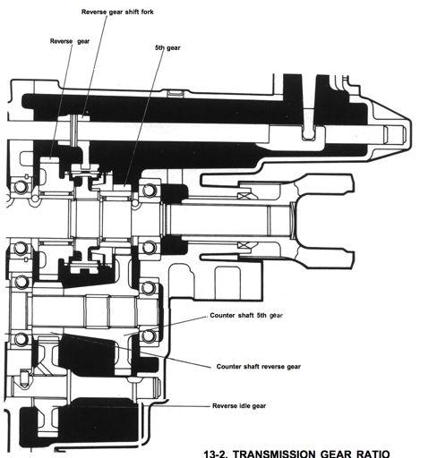
11 Backup Light Switch Upper Transmission Case 5th Gear Light Switch Extension Case Lower Transmission Case Input Shaft Housing


")
12 Step 19 Remove the extension case bolts. Step 20 Continue removing the extension case bolts. Step 21 Remove the (9) transmission upper case bolts. Step 22 Remove the (8) input shaft housing bolts.


13 Step 23 Remove the 5th/reverse rod locating bolt as well. Step 24 Prop up the rear of the transmission using a 2X4X12 board. Step 25 Jar the extension case loose by tapping it with a hammer as shown. Caution: Do not strike hard. Cast aluminum is easily broken. Step 26 Pull the extension case back about an inch. Do not attempt to remove it all the way at this point.


14 Step 27 Reach inside the extension case and pull the reverse idler gear toward the rear of the transmission so it stays with the extension case. Step 28 Continue removing the extension case. The reverse idler gear will soon drop out the bottom. Be sure to catch it. Set the extension case and the reverse idler gear aside for now. Step 29 Remove the 2X4 board. Step 30 Begin the removal of the top transmission case by prying gently with a large standard screwdriver in the location shown here.


15 Step 31 Continue the removal of the transmission upper case by prying as shown here. Caution: Do not gouge the case halves with the screwdrivers. Step 32 Continue working the upper and lower cases apart with the screwdriver. You may need to hit the shifter rods with the heel of your hand as well to help separate the cases. Step 33 Continue working the upper case until it is separated from the lower case. Step 34 Remove the input shaft housing by tapping it with a hammer. If it does not come loose easily you will need to go to the next Tech Tip.


16 Tech Tip 34 Thread two 6X1.0X25mm bolts in the locations shown here. Tighten them in an increasingly tighter back-and-forth pattern until the housing breaks loose. Step 35 Remove the input shaft housing. Step 36 Inspect the housing for wear and damage. Pay particular attention to the area that supports the throwout bearing. (See Arrow) If wear is noted, replace the housing.
17 Main shaft center bearing


18 Step 37 Lift out the main shaft assembly.... Step and set it aside. Be sure to protect the gears by placing a cloth under it. Removing the Counter Shaft Step 39 Leave the lower transmission case on the bench. Step 40 Strike the counter shaft from the rear using a ball peen hammer. Strike the shaft squarely so as not the mushroom the end of the shaft.


19 Step 41 Continue striking the counter shaft until you can remove the snap ring at the other end of the shaft. Step 42 Remove the snap ring using a pair of snap ring pliers. Step 43 Remove the countershaft rear bearing and the countershaft 5th gear together, using a three jaw puller as shown here. Step 44 Remove the countershaft reverse gear.


20 Step 45 Place a cloth under the countershaft prior to the next step to keep the countershaft from becoming damaged during removal. Step 46 Strike the countershaft sharply using a brass hammer rearward until the front and rear bearings are free from the case. Tech Tip 46 This shows the countershaft nearly free from the case. Step 47 Once the countershaft bearings are free from the case, slide the countershaft rearward as shown here.


21 Step 48 Install the gear puller as shown here and force the rear countershaft bearing rearward. Step 45 Remove the rear countershaft bearing. Note: Normally you would not remove a bearing by pulling against the outer bearing race because this can damage the bearing. But it is okay here we are replacing this bearing. Step 50 Remove the countershaft. Step 51 Carefully inspect the counter shaft for unusual gear wear patterns, cracked, damaged or missing teeth. Replace if necessary.


22 How to Inspect Gears & Synchronizer Hubs. Note: Synchronizers do not need inspection. They are supplied in the kit. Gear Inspection These teeth should be pointed and uniform all the way around. These teeth should be smooth with no unusual wear patterns.no chipped, broken or missing teeth. No discoloration. This surface should be smooth, shinny & without discoloration. Synchronizer Hub Inspection These teeth should be pointed and diamond shaped. Not flattened or damaged in any way. Inpect other side of the synchronizer hub as well.

23 How to Inspect Bearings & Sleeves Bearing rollers should be smooth and shinny with out chips, cracks or discoloration. Bearing cage should hold rollers secure and equally spaced around the shaft. Cage not broken or chipped. Main shaft should be smooth and shinny without chips, cracks or discoloration. Inside of sleeves should be smooth and shinny without chips, cracks, scratches or discoloration. Outside of sleeves should be smooth and shinny without chips, cracks, scratches or discoloration.


24 Disassembling the Main Shaft Step 52 Lay out a couple of cleaning cloths to protect the main shaft assembly and a third cloth to place the parts on as they are removed. Tech Tip 52 It is wise to set all the parts that are removed from the main shaft in the order of removal so they can be reinstalled in reverse order. Step 53 Lay the main shaft as shown. Step 54 Remove the input shaft assembly. Inspect the input shaft gear and synchronizer teeth. Also, inspect the tip of the shaft that is supported by the pilot bearing. See Arrow.


25 Step 55 Remove and inspect the input shaft bearing. Step 56 Remove the first high speed synchronizer ring. Note: This part is supplied in the kit. Step 57 Remove the high speed hub circlip using two standard screwdrivers of equal length. Simply hit both screwdrivers simultaneously with the heel of your hand. Tech Tip 57 This shows the positioning of the two screwdrivers on the circlip.


26 Step 58 Remove and inspect the high speed synchronizer hub set. Step 59 Remove the second high speed synchronizer ring. Note: This part is supplied in the kit. Step 60 Remove and inspect 3rd gear. Step 61 Remove and inspect the third gear bearing.


27 Step 62 Turn the main shaft assembly around. Step 63 Remove the rear bearing circlip with the two screwdrivers as before. Step 64 Remove the main shaft rear bearing using a 3 jaw puller as shown. Step 65 Remove the 5th gear washer. Note: Normally you would not remove a bearing by pulling against the outer bearing race because this can damage the bearing. But it is okay here, we are replacing this bearing.


28 Step 66 Remove the 5th gear washer ball. Tech Tip 66 To remove this type of ball, wipe it clean with a cloth. Once it is clean, rotate the shaft and the ball will fall out on the cloth. Step 67 Remove and inspect 5th gear. Step 68 Remove 5th gear synchronizer ring. Note: This part is supplied in the kit.


29 Step 69 Remove and inspect the 5th gear bearing. Step 70 Remove the next circlip with the two screwdrivers as before. Step 71 Remove and inspect the reverse synchronizer hub set. Step 72 Remove and inspect the reverse gear.


30 Step 73 Remove and inspect the reverse gear bearing. Step 74 Remove and inspect the reverse gear sleeve. Step 75 Remove the main shaft bearing washer. Step 76 Remove the main shaft bearing washer ball.


31 Step 77 Install a bearing puller as shown here. Step 78 Set up the main shaft in a press as shown here. Step 79 Force the main shaft down using the press. Be sure to catch the main shaft as it becomes free from the bearing. Step 80 Remove the main shaft bearing washer.


32 Step 81 Remove the washer ball. Step 82 Remove and inspect 1st gear. Step 83 Remove the 1st gear synchronizer ring and spring. Step 84 Remove the 1st gear bearing.


33 Step 85 Remove and inspect the 1st gear sleeve. Step 86 Remove and inspect the high speed synchronizer hub set. Step 87 Remove the high speed synchronizer spring and ring. Step 88 Remove and inspect 2nd gear.


34 Step 89 Remove and inspect the 2nd gear bearing. These areas should be smooth, shinny and free from pits, scoring or discoloration. Step 90 Inspect the main shaft.
35 Detent Spring (3) Detent Groove Neutral Detent Ball (2) 1st/2nd Sifter Rod Detent Ball (3) Neutral Detent Pin Roll pin 3rd/4th Shifter Rod 5th/Revers shifter Rod 1st/2nd Sifter Fork 3rd/4th Shifter Fork 5th/Revers Shifter Fork 5th/Revers Rod Locating Bolt


36 Step 91 Place the transmission upper case on a 2X4 as shown. Step 92 Position the (3) sifter rods in neutral position if they are not there already. Step 93 Drive the 3rd/4th shifter fork roll pin downward using a 3/16 pin punch. Continue until the shaft is free to slide inside the fork. Step 94 Drive the 1st/2nd shifter fork roll pin down until the shaft is free to slide in the fork. Note: This should free the shifter fork from the shaft so the shaft can be removed.


37 Step 95 Place your finger over the 5th/reverse detent ball hole to prevent the ball and spring from flying out and slide the 5th/ reverse shifter rod out of the upper case. Step 96 Place your finger over the 1st/2nd detent ball hole to prevent the ball and spring from flying out and slide the 1st/ 2nd shifter rod out of the upper case. Tech Tip 96A Sometimes the shifter rod will get a few b u r r s n e a r t h e d e t e n t g r o o v e s preventing the rod from coming out of the case. If this happens, do not force the rod out of the case. Push the rod back into the case so that the detent ball grooves are visible and remove the burrs using emery cloth. Tech Tip 96B Lightly sand in the areas indicated by the arrows. Once the burrs are removed remove the 1st/2nd shifter Rod. Once the rod is removed, remove the 1st/2nd shifter fork from the transmission upper case.


38 Detent Pin Step 97 Repeat previous steps on the 3rd/4th shift rod and fork with only one exception. See the next Tech Tip. Tech Tip 97A Caution!!! As you slide the 3rd/4th shift rod out. Be sure to retrieve the detent pin. You will need it when reassembling the transmission. If this is lost or not installed properly, the transmission will not shift correctly. Step 98 Once all the shifter rods are out remove the detent balls and springs. This is done by placing a cloth on the table and turning the transmission upper case over. 5 balls and three springs should fall out. It may be necessary to lightly tap the case on the bench.


39 Removing the Counter Shaft Front Bearing Step 99 Remove the front bearing circlip using two standard screwdrivers. Step 100 Install the bearing puller on the front bearing as shown here. Step 101 Place the counter shaft in a press as shown here and force the shaft down. Be sure to catch the shaft as it comes free from the bearing. Tech Tip 101 Bearing removed from the countershaft.


40 Removing the Input Shaft Bearing C-clip Step 102 Remove the input bearing C-Clip. Important: Be sure to save this clip as it will be needed with the new bearing. Step 103 Remove the circlip using two standard screwdrivers. Step 104 Position the bearing puller as shown here. Step 105 Place the input shaft in a press as shown and force the input shaft downward. Be sure to catch the input shaft as it comes free from the bearing.


41 Tech Tip 105 Bearing removed from the input shaft. Removing the Input Shaft Seal Step 106 Place a seal hook under the seal and pry it out. Tech Tip 106 This shows the seal removed.


42 Removing the Output Shaft Seal & Bushing from the Extension Case Seal Bushing Step 107 We have found it best to push the bushing and seal out of the extension case, both parts at the same time. You will need to find a tool that is large enough to contact the bushing, but small enough to fit through the hole in the extension case. (See next Tech Tips) Tech Tip 107A This is a custom built slide hammer tool we designed and built for driving out the bushing and seal Step 107B These are the diminutions of the tool we made. You may be able to find a socket that will fit the dimension or at least come close enough to do the job. It is kind of hard on the socket but it can be done. Step 108 Place the extension case on a block of wood and drive the bushing and seal out. (See next 3 Tech Tips before driving out the bushing and seal)


43 Support Here NOT Here Tech Tip 108A Be sure to support the extension case on a block of wood as shown. Tech Tip 108B Seal and bushing driven out. A B Tech Tip 108C This shows how the tool fits the bushing once the bushing has been removed from the case. Be sure that the tool at point A is smaller than the outside diameter of the bushing at point B. Tech Tip 108C This concludes the disassembly process. Of course you will want to clean all the parts your will need for reassembly. Continue to the next page when you are ready for reassembly.
44 Instructions Created by an: Suzuki Samurai Samurai Complete Transmission Rebuild Kit with Synchronizers (SKU# STM-RP) Installation Instructions Part II Disassembly Notice: We will be basing these instructions on a complete transmission rebuild just like we do for our customers. You may not be replacing all the parts that we do. If we show replacing a part you are not replacing, simply skip those steps and move on the procedures you need. If you find there are parts that you need but are not included in the kit, there is a good chance they can be found on our website. If you cannot find the part you need on our website, feel free to give us a call, there is a good chance we can help you find it. Additionally, we are not showing the cleanup of all the parts. We will assume you know how to do that. Simply put, just make sure all the parts (transmission cases, extension case, shifter tower, release lever, input shaft housing, shifter rods, shifter forks, etc) are all cleaned and free of grease, dirt, old gaskets, etc. You should also reassemble this transmission on a clean work surface in a dust free environment.
45 Samurai Transmission Parts Identification 4th Gear 1st Gear

46 Main shaft center bearing

47 Step 1 Set out all the main shaft parts as shown here. 1-2nd Gear, Synchro Ring and Spring 2-1st/2nd Synchronizer Hub 3-1st Gear, Synchro Ring,Spring, and Sleeve Sleeve 4 - Bearing Washer & Ball 7 - Reverse Gear & Sleeve 8-5th/Reverse Synchronizer Hub Sleeve Circlip 5 - Main Shaft Front 6 - Bearing Washer & Ball 9-5th Gear & Synchro Ring Circlip 12-3rd Gear & Synchro Ring Red numbers indicate the order in which these parts are to be installed on the main shaft. 13-3rd/4th Synchronizer & Circlip 11 - Main Shaft Rear Bearing & Circlip 10 - Bearing Washer & Ball


48 Step 2 Set out the main shaft and a tub of good quality high temperature wheel bearing grease. Test Fitting and Replacing the Synchronizer Rings Step 3 Remove the old 2nd gear synchronizer ring and spring. Step 4 Install the new 2nd gear synchronizer ring and spring. Note: Be sure the new synchronizer matches the shape and size of the gear as did the old one. On rare occasion we have been shipped the wrong synchronizer rings from our supplier.


49 Step 5 Repeat Steps 3 and 4 on 1st Gear. Step 6 Repeat Steps 3 and 4 on 5th gear. Note: This synchronizer does not have a spring with it as did 1st and 2nd gear synchronizer rings. Step 7 Repeat Steps 3 and 4 on 3rd gear. There is no synchronizer spring here either.


50 Matching up and Laying Out the Main Shaft Bearings Step 8 Swap out the old main shaft front bearing with the new one. Compare the bearing numbers to insure you have the correct bearing. Step 8 Continued Remove the C-Clip from the old bearing.... Step 8 Continued..... and install it on the new bearing Step 9 Swap out the old main shaft rear bearing with the new one. Compare the bearing numbers to insure you have the correct bearing.

51 Tech Tip 9 Unlike the old main shaft rear bearing, the new bearing may have a snap ring groove with a snap ring in it. As long as the numbers match, this bearing will work. However, you will need to remove the snap ring from the new bearing. It will not be needed in this application.


52 Matching up and Laying Out the Main Shaft Needle Bearings Step 10 Ready the new needle bearings by placing them with the correct gears. 2nd Gear, Synchro Ring and Spring Reverse Gear 1st Gear, Synchro Ring and Spring 1 Small Size Bearing 3 Larger Size Bearings 1 Split Bearing 3rd Gear & Synchro Ring 5th Gear & Synchro Ring


53 Step 11 Once all (5) needle bearings are placed where they are to be installed.... Step 11 Continued... test fit each one to insure it fits correctly. Sleeve Bearing Tech Tip 11A The bearing will fit between the sleeve and gear on the 1st Tech Tip 11B.... and reverse gears.


54 Assembling the Main Shaft High Temperature wheel bearing grease will be applied to may parts during assembly. This is to provide temporary protection for these parts until gear oil can find its way to them. Failure to use grease during reassembly could damage these part and greatly reduce the life of the transmission. Step 12 Stand the main shaft on the work bench with the output splines up. Step 13 Apply bearing grease to the inside of the 2nd gear needle bearings. Note: Work the grease into the bearing cage and around all the needle bearings. Step 14 Install the 2nd gear bearing on the main shaft. Step 15 Apply bearing grease to the bottom thrust face of 2nd gear.


55 Don t forget the spring! Step 16 Apply grease to the synchronizer surface of 2nd gear. Step 17 Install the 2nd gear synchronizer and spring. Step 18 Install grease to the outside of the second gear synchronizer ring. Step 19 I n s t a l l t h e 2 n d g e a r a s s e m b l y (synchronizer up) on the main shaft.


56 Step 20 Install the 1st/2nd synchronizer hub on the main shaft as shown. Tech Tip 20 Rotate the synchronizer until it sits down in place as shown. Step 21 Install the 1st gear sleeve on the main shaft. Tech Tip 21 The 1st gear sleeve must fit below the ball hole as shown. If it does not, you will need to check previously installed items for proper fit.


57 Step 22 Apply bearing grease to the inside of the 1st gear bearing. Step 23 Install the 1st gear bearing over the sleeve. Don t forget the spring! Step 24 Apply grease to the synchronizer surface of 1st gear. Step 25 Install the 1st gear synchronizer ring and spring.


58 Step 36 Apply grease to the back side of the synchronizer ring. Step 27 Install 1st gear on the main shaft and over the bearing. Note: Be sure the synchronizer ring is facing down. Step 28 Install the washer locating ball. Step 29 Install the bevel up. bearing washer with the Note: Be sure to align the notch in the washer with the ball.


59 Tech Tip 29 This shows the bearing washer properly installed. Step 30 Install the main shaft center bearing. Note: C-clip toward the top of the main shaft DOM (.250 Wall) Pipe 1.75 Outside Diameter 1.25 Inside Diameter 8 Long Step 31 Force the main shaft center bearing in place by using a hydraulic press or a pipe and hammer as shown here. (See next Tech Tip for Pipe dimensions) Tech Tip 31 This is the dimensions on the pipe we used. Note: Continue pounding until the bearing is firmly seated against the washer.


60 Step 32 Install the washer locating ball as shown. Step 33 Install the second bearing washer bevel side down. Note: Be sure the notch in the washer aligns with the ball and the flat side of the washer is oriented upward. Step 34 Install the reverse gear sleeve. Step 35 Apply bearing grease to the inside of the reverse gear needle bearing.


61 Step 36 Install the reverse gear needle bearing over the reverse gear sleeve. Step 37 Apply bearing grease to the inside of the reverse gear. Step 38 Apply grease to the thrust face of the reverse gear. Step 39 Install the reverse gear over the bearing with the synchronizer teeth upward.


62 Step 40 Install the 5th/reverse synchronizer hub. Note: The wider face of the synchronizer hub goes down. Step 41 Lay the main shaft on its side and install the circlip. Note: Place a cloth under the assembly for protection. Tech Tip 41A Snap the circlip in place by prying downward using a large standard screwdriver. Tech Tip 41B Insure the circlip is seated by tapping it downward using a punch (or a large standard screwdriver) and a hammer.


63 Step 42 Apply bearing grease to one half of the 5th gear needle bearing. Step 43 Place the first half of the needle bearing on the main shaft. Step 44 Apply bearing grease to the second half of the 5th gear needle bearing. Step 45 Place this needle bearing on the main shaft opposite the first one.


64 Step 46 Apply bearing grease to the synchronizer side of of the 5th gear. Step 47 Install the 5th gear synchronizer ring on 5th gear. Step 48 Apply bearing grease to the outside of the 5th gear synchronizer ring. Step 49 Install 5th gear over the 5th gear bearing with the synchronizer facing down.


65 Step 50 Install the washer ball. Step 51 Apply grease on the top side of 5th gear. Step 52 Install the 5th gear bearing washer as shown. Tech Tip 52 Be sure to align the notch of the washer with the ball. Note: Install this washer with the grooved side down. Grooved Side


66 Step 53 Install the main shaft rear bearing. Step 54 Force the main shaft rear bearing on the main shaft using a hydraulic press or a pipe and hammer as shown here. Step 55 Continue pressing the bearing until there is sufficient room for the circlip to be installed. Step 56 Install the circlip by snapping it into place using a punch (or large standard screwdriver) and a hammer.


67 Tech Tip 56 Be sure the circlip is sitting all the way down in the groove of the main shaft. Step 57 Turn the main shaft around. Step 58 Apply wheel bearing grease to the inside of the 3rd gear needle bearing. Step 59 Install the 3rd gear needle bearing on the main shaft as shown here.


68 Step 60 Apply grease to the back side of 3rd gear as shown. Step 61 Apply grease to the synchronizer side of 3rd gear. Step 62 Install the 3rd gear synchronizer ring on 3rd gear. Step 63 Apply grease to the outside of the synchronizer ring.


69 Step 64 Install third gear over the bearing. Step 65 Install the 3rd/4th synchronizer hub on the main shaft with the grooved side toward 3rd gear. Tech Tip 65 There should be enough room to install a circlip in the groove of the main shaft. If not, check all parts associated with the 3rd gear for proper fit and correct as needed. Step 66 Position the circlip as shown.


70 Step 67 Snap the circlip into place using a large standard screwdriver. Step 68 Set the main shaft aside for now. Note: Be sure it is seated all the way down in the groove. Assembling the Input Shaft Step 69 Remove the snap ring from the front (or input shaft) bearing using snap ring pliers. Step 70 Place the input shaft on the workbench as shown and place the front bearing on the shaft. Note: This snap ring can be discarded. It will not be used in this application.


71 Step 71 Force the bearing on the input shaft using a press or hammer and pipe as shown here. Step 72 support the pilot bushing end of the input shaft on a block of wood and 4th gear on a cloth. Then position the circlip in the groove. Note: This circlip was removed from the input shaft during disassembly. Step 73 Snap the circlip into place using a large standard screwdriver and hammer. Step 74 Reinstall the C-Clip on the front bearing in the groove. Note: This C-Clip was removed from the old front bearing during disassembly.


72 Step 75 Apply grease to the synchronizer surface of 4th gear. Step 76 Install the 4th gear synchronizer ring. Step 77 Apply a liberal amount of bearing grease inside of the input shaft bearing cavity. Step 78 Install the input shaft needle bearing.


73 Step 79 Apply more bearing grease to the inside of the bearing. Step 80 Apply bearing grease to the outside of the synchronizer ring. Step 81 Install the input shaft assembly onto the front of the main shaft assembly. Step 82 The main shaft is now ready for installation in the transmission case. Simply set it aside for now.


74 Center Bearing 5th Gear Counter Shaft Circlip Reverse Gear Rear Bearing Front Bearing Assembling the Counter Shaft Step 83 Lay the counter shaft on the work bench. Note: Lay a cloth under the shaft for protection. Step 84 Select the new counter shaft front bearing by comparing the numbers on the side of the bearing. The new front counter shaft bearing should have a snap ring in place.


75 Step 85 Place the front counter shaft bearing on the counter shaft as shown. Note: Snap ring up. Step 86 Force the bearing on the counter shaft by striking it sharply with a ball peen hammer. Be sure to strike the bearing on the inner race only. Continue driving the bearing until it is flush with the shaft. Step 87 Once the bearing is flush with the shaft, continue driving the bearing on using the pipe and hammer. Continue driving the bearing until it seats against the gear and the circlip groove is fully exposed. Step 88 Position the circlip in the counter shaft groove. Note: Reuse the circlip from the counter shaft.


 in first.")
76 Step 89 Snap the circlip into place using a large screwdriver and hammer. Step 90 Remove the snap ring from the front countershaft bearing using snap ring pliers. Note: Keep this snap ring it will be used later. Assembling the Counter Shaft in the Transmission Lower Case Step 91 Install the counter shaft in the transmission lower case by inserting the rear end (smaller gear end) in first. Step 92 After the rear of the counter shaft is positioned in the case, slide it forward positioning the front counter shaft bearing in the case.


77 Step 93 Place the transmission lower case on the work bench as shown and drive the front bearing about half way into position in the case. DO NOT drive the bearing all the way into position at this time. Step 94 Install the counter shaft center bearing on to the counter shaft. Step 95 Using the pipe and hammer drive the center bearing into the counter shaft. Step 96 Continue driving the counter shaft rear bearing on to the shaft and into the case. Continue driving the bearing into the case until it is about a 1/4 above the case as shown here.


78 Step 97 Install the counter shaft reverse gear. Step 98 Install the counter shaft 5th gear. Step 99 Position the counter shaft rear gear bearing. Step 100 Drive this bearing into place using a ball peen hammer. Caution: Be sure to strike the bearing squarely by hitting the center race. DO NOT strike the outer race of the bearing.


79 Tech Tip 100 The bearing should be flush with the counter shaft at this point. Step 101 Continue driving the counter shaft downward until the snap ring can be reinstalled on the counter shaft front bearing. See Next Tech Tip. Tech Tip 101 The front bearing groove should be fully visible. Step 102 Once the front bearing groove is fully visible, install the snap ring in the counter shaft front bearing groove.


80 Step 103 Now drive the counter shaft and front bearing rearward until the snap ring is secure against the transmission case. Step 104 Check for any lateral (in-out) movement of the 5th gear. Note: Be sure to strike the shaft squarely so as not to mushroom the shaft. Step 105 If movement is found to be present, position the pipe on the front of the counter shaft and strike the inner race of the fifth gear bearing as shown. Step 106 Check for lateral movement again. If movement is felt repeat the previous step until there is no movement.


81 Installing the Main Shaft in the Transmission Lower Case Step 107 Place the transmission lower case on the work bench. Step 108 Position the main shaft assembly as shown here and carefully lower it into place. Tech Tip 108A Insure that the rear bearing C-clip is positioned in the case groove and that the end of the C-clip ring is in the 12 o clock position. Tech Tip 108B Insure that the front bearing C-clip is positioned in the case groove and that the end of the C-clip ring is at the 12 o clock position. Additionally, these C- clips should be opposite each other, one C-clip toward the right side of the case and the other toward the left. See Tech Tip C.
82 Tech Tip 108C C-clips should be opposite each other. One toward the left side of the case the other toward the right.


83 Installing Reverse Idler Gear Notch Tab Pin Tech Tip 109 When installing the reverse idler gear insure that the pin and tab on the shaft are oriented toward the notch in the lower case. Step 109 Install the reverse idler gear in the lower housing. Testing the Transmission for Correct Operation in All Gears Step 110 Check to see that the main shaft and the counter shaft turn with out binding. Step 111 Shift the transmission into 1st gear and check for correct operation.


84 Step 112 Shift the transmission into 2nd gear and check for correct operation. Then move the 1st/2nd synchronizer hub back into neutral position. Step 113 Shift the transmission into 3rd gear and check for correct operation. Step 114 Shift the transmission into 4th gear and check it for correct operation. Then move the 3rd/4th synchronizer hub back into neutral position. Step 115 Shift the transmission into 5th gear and check for correct operation.

85 Step 116 Shift the transmission into reverse gear and check for correct operation. Then move the 5th/Reverse synchronizer hub back into neutral.

86 Transmission Upper Case Assembly Transmission Upper Case 1st/2nd Sifter Fork 1st/2nd Sifter Rod 3rd/4th Shifter Rod 3rd/4th Shifter Fork 5th/Revers Shifter Rod 5th/Revers Shifter Fork

87 Shifter Fork Assembly Detent Spring (3) Detent Groove Neutral Detent Ball (2) 1st/2nd Sifter Rod Detent Ball (3) Neutral Detent Pin Roll pin 3rd/4th Shifter Rod 5th/Revers shifter Rod 1st/2nd Sifter Fork 3rd/4th Shifter Fork 5th/Revers Shifter Fork 5th/Revers Rod Locating Bolt


88 Assembling the Transmission Upper Case Shifter Rods and Forks Step 117 Place the transmission upper case on the work bench. Step 118 Install one detent spring in each of the 3 holes. Step 119 Position the 3rd/4th shifter fork on the work bench and drive the roll pin back into its original position. Step 120 Continue driving the roll pin through the shifter fork until it can be reinstalled on the shifter rod with out obstruction.


89 Tech Tip 120 This shows the roll pin properly positioned, ready for installation on the shifter rod. Step 121 Repeat Steps 119 and 120 on the 1st/ 2nd shifter fork. Step 122 Place a 2x4 under the rear of the upper case. Insert the 3rd/4th shifter rod into the middle position in the transmission upper case. Step 123 Stop when the rod is positioned as shown here.


90 Step 124 Drop a detent ball in the center hole. Step 125 Using a small screwdriver, push the ball down against spring tension and continue pushing the shift rod into place. Step 126 Install the 3rd/4th shifter fork on the end of the shift rod. Note: DO NOT drive in the roll pin yet. Step 127 Install the neutral detent pin in the 3rd/ 4th shifter rod. Then rotate the shifter rod so that the detent pin in perfectly horizontal and the detent grooves in the rod are facing down.


91 Step 128 While holding the 3rd/4th shifter fork in place continue pushing the shifter rod in to place. Continue inserting the rod until it reaches the NEUTRAL (second click) position. DO NOT drive the shifter fork roll pin into place yet. DO NOT tilt the case at this point. The the neutral detent pin will fall out of place. Step 129 Insert the 1st/2nd shifter rod into the rear of the transmission upper case as shown. Step 130 Position the 1st/2nd shifter fork on the end of the shifter rod. Step 131 While holding the shifter fork stationary, continue inserting the shifter rod, but stop just before the rod enters the detent ball hole.


92 Step 132 Install 1 of the 2 neutral detent balls in the hole as shown. Note: It really doesn t matter which ball you use. All 5 detent balls are the same size. Step 133 Push the neutral detent ball sideways against the neutral detent pin that was installed earlier. Step 134 Drop another detent ball in the same hole. It should rest on top the detent spring. Step 135 Using a screwdriver, push down on the ball and continue inserting the shifter rod.

 position.")


93 Step 136 Turn the shifter rod until the detent grooves are facing downward. Position the shifter rod in the neutral (second click) position. DO NOT drive the shifter fork roll pin into place at this time. Step 137 Insert the 5th/reverse shifter rod and fork into the rear of the upper case as shown. Step 138 Stop just short of the detent ball holes. Step 139 Drop the 2nd neutral detent ball into the hole as shown.


94 Step 140 Using a screwdriver, push the neutral detent ball sideways against the neutral detent pin. Step 141 Drop the last detent ball in the same hole as shown. Step 142 While holding the detent ball down with a screwdriver, continue inserting the 5th/ reverse shifter rod. Once the rod is keeping the ball in place, rotate the shifter rod so that the detent grooves are facing downward. Step 143 Continue inserting the 5th/reverse shifter rod until it reaches neutral (2nd click) position.


95 Tech Tip 143 Double check that all 3 shift rods are in neutral position by looking at the shifter lever assembly. All should be aligned as shown here. Step 144 Align the 1st/2nd shifter fork roll pin with the hole in the shifter rod and drive in the roll pin using a punch and hammer. Step 145 Align the 3rd/4th shifter fork roll pin with the hole in the shifter rod and drive in the roll pin using a punch and hammer. Tech Tip 145 Both roll pins should be flush with the surface of the shift fork.


96 Installing the Input Shaft Seal Step 146 Position the input shaft seal in the input shaft housing. The garter spring of the seal should oriented UP. Step 147 Drive the seal into place using a 32mm socket and hammer. Step 148 Continue driving the seal until it is flush with the surface of the input shaft housing.


97 Installing the Output Shaft Bushing & Seal Hole Groove Step 149 Place the extension case on the work bench as shown. Note: The case should sit flat against the workbench. If there are locating dowels in the extension case preventing the case from sitting flat, place the case on a 2x4. Step 150 Position the output shaft bushing in the extension case as shown. Caution: Be sure to align the hole in the bushing with the groove in the case before driving the bushing in. Failure to align the hole and groove WILL result in poor lubrication of the output yoke leading to premature failure of the yoke and bushing. Step 151 Using the same tool used to remove the old bushing, drive in the new bushing. Note: See disassembly instructions (Pg 42, Step 107B) for the dimensions of this tool. Tech Tip 151A Continue driving in the bushing until it is flush with the extension case.


98 Tech Tip 151B Inspect the bushing from the inside of the extension case to see that the hole and groove align properly. Step 152 Test the fit of the bushing with an output yoke to see that there is little side to side movement. Step 153 Position the output shaft seal as shown. Note: Position the garter spring downward. Step 154 Drive the output shaft seal into place using a 32mm socket and hammer.


99 Tech Tip 154 The edge of the seal should be flush with the case. Installing the Transmission Upper Case on the Lower Case A B Step 155 Apply bearing grease to the upper portion of all three synchronizer hubs. Step 156 Insure that the locator dowels are positioned properly. Dowel A should be located in either the lower case or upper case. Dowel B should be in either the upper case or lower case.


100 Step 157 Dry fit (assemble without gasket maker) the transmission upper case onto the lower case. Make sure the shifter forks align with the synchronizer hubs and the dowel pins align with the holes. Step 158 Once you are confident the cases will come together properly, remove the upper case. Step 159 Apply a thin layer of Permatex Ultra Gray Silicone Gasket Maker to the lower case as shown in the next Tech Tip


101 Tech Tip 159 This shows where to apply the gasket maker. Step 160 Place the upper case back on the lower case as before. Step 161 Install the case bolts. See next Tech Tip for bolt size and location.


102 Tech Tip 161 This shows the bolt size and location 120 = M8X1.25X120mm 65 = M8X1.25X65mm 30 = M8X1.25X30mm Step 162 Snug all the bolts using a 12mm socket and ratchet. Step 163 Torque all the bolts using a progressively tighter criss-cross pattern until 15 ft. lbs is reached.


103 Step 164 Plug this hole with Ultra Gray Silicone Gasket Maker. Installing the Transmission Extension Case Step 165 Prop-up the rear of the transmission with a 2X4 as shown. Step 166 Apply a thin coat of Ultra Gray Silicone Gasket Maker to the transmission case where the extension case will contact. See the next Tech Tip to see where to apply sealer.

104 Step 167 This shows where to apply the gasket maker. Step 168 Be sure the (2) locating dowels are in place. Step 169 Begin installing the extension case. Be sure the reverse idler shaft, shifter rods, output shaft, counter shaft bearing and output shaft bearing are all positioned properly.


105 B A Step 170 Continue working the extension case into place. You should be able to get the extension case within about 3/4 of an inch by hand. Step 171 Once you are sure that all the internal parts are positioned properly, tap the extension case at point A. The case should continue moving closer with each tap of the hammer. You may have to tap at point B as well. Step 172 Once the extension case is snug against the transmission case, install the bolts as shown in the next Tech Tip. Caution: DO NOT draw the extension case in place using the bolts.


106 Tech Tip 172 This shows the location and size of the bolts = M8X1.25X = M8X1.25X100 Step 173 Snug the (10) bolts using a 12mm socket and ratchet. Step 174 Tighten the (10) bolts using an increasingly tighter criss-cross pattern until 15 ft. lbs. is reached.


107 Step 175 Install and torque the reverse gear shift rim bolt to 15 ft. lbs. Step 176 Install the oil filler plug. Note: Just hand tight for now. Step 177 Install the drain plug. Step 178 Tighten the drain plug using a 24mm socket.


108 Step 179 Tighten the oil filler plug using a 24mm socket. Step 180 Apply a small amount of bearing grease to the surface of the input shaft. Step 181 Apply a thin layer of Ultra Gray Silicone Gasket Maker to the input shaft housing. Tech Tip 181 This shows where to apply the gasket maker.


109 Step 182 Install the input shaft housing. Step 183 Install the input shaft housing bolts. Note: All 8 bolts are M8X1.25X25. Step 184 Snug the input shaft housing bolts using a 12 mm socket and ratchet. Step 185 Torque the input shaft bolts in an increasingly tighter criss-cross pattern until you reach 15 ft. lbs.
110 Clutch Release Parts Clutch Release Lever Nut Clutch Release Shaft Seal Clutch Release Shaft Bushing Clutch Release Forks Clutch Release Lever Bolt Clutch Release Shaft Clutch Release Shaft Spring Clutch Release Lever Clutch Release Shaft Plug Clutch Release Shaft Bushing Clutch Release Bearing Clutch Disc Pressure Plate


111 Installing the Clutch Release Assembly Step 186 Install the release lever spring as shown. Step 187 Install the clutch release shaft, the non spring end first.... Note: Be sure to place the hook over the fork. Step and then the other. Step 189 Position the spring as shown.


112 Step 190 Install the driver side clutch release shaft bushing using a hammer. Step 190 Continued Continue driving in the bushing until it is flush with the housing. Step 191 Insure the release shaft is properly positioned inside the driver side bushing. Step 192 Continue driving in the bushing until it is about 1/4 inside the case as well.


113 Step 193 Install the passenger side release shaft bushing. Step 194 Drive the bushing into place using a 14mm deep socket. Tech Tip 194 Continue driving the bushing into the case until it is about 1/4 inside the case. Step 195 Install the release shaft seal.


114 Step 196 Tap the seal into place using a 14mm deep socket and hammer. Tech Tip 196 The seal should be flush with the case. Step 197 Position the release shaft plug on the driver side as shown. Step 198 Drive the release shaft plug into place using a 14mm deep socket and hammer.


115 Tech Tip 198 The plug should be slightly deeper than flush with the case. Step 199 Install the clutch release lever onto the release shaft. Note: Be sure the two dots are aligned. Step 200 Tighten the clutch release lever pinch bolt using a 12 mm socket. Step 201 Install the Ignition Timing plug.


116 Installing the Shifter Tower Step 202 Apply a thin coat of Ultra Gray Silicone Gasket Maker where the shifter tower is to be installed. Step 203 Install the shifter tower. Step 204 Install the (4) shifter tower bolts. Step 205 Snug these bolts then torque them to 15 ft. lbs.


117 Step 206 Temporarily install the shift lever and shift the transmission in to all gears. Conclusion! This concludes our instructions for rebuilding a Samurai transmission. We hope they have been helpful. If you need help with installing a clutch, transmission, or anything else on your Samurai we invite you to our website. Simply click on the Instructions tab and select Samurai.

118 As always, If you experience any difficulty during the installation of this product please contact Low Range Off-Road Technical Support at M-F 7:30am-5:30pm MST. Thank you for purchasing from Low Range Off-Road. These instructions are designed as a general installation guide. Installation of many Low Range Off-Road products require specialized skills such as metal fabrication, welding and mechanical trouble shooting. If you have any questions or are unsure about how to proceed, please contact our shop at or seek help from a competent fabricator. Using fabrication tools such as welders, torches and grinders can cause serious bodily harm and death. Please operate equipment carefully and observe proper safety procedures. Rock crawling and off-road driving are inherently dangerous activities. Some modifications will adversely affect the on-road handling characteristics of your vehicle. All products sold by Low Range Off-Road are sold for off road use only. Any other use or application is the responsibility of the purchaser and/or user. Some modifications and installation of certain aftermarket parts may under certain circumstances void your original dealer warranty. Modification of your vehicle may create dangerous conditions, which could cause roll-overs resulting in serious bodily injury or death. Buyers and users of these products hereby expressly assume all risks associated with any such modifications and use. Revised 05/22/14 Copyright 2014 Low Range Off-Road, LC All Rights Reserved
Installation Instructions
 Instructions Created by an: Inchworm Tacoma Dual Case Adapter Installation Instructions Suggested Tools: CAUTION: Safety glasses should be worn at all times when working with vehicles and related tools
Installation Instructions
 Instructions Created by an: Inchworm Gear Clockable Toyota Dual Transfer Case Adapter Kit, 21 or 23 Spline SKU# TCASE-IW-300-000 Installation Instructions CAUTION: Safety glasses should be worn at all
Suzuki Samurai to Toyota Front Spring Swap Kit, with Missing Link Shackles (SKU#SSP-TSFM) Installation Instructions
 Installation Instructions") Suzuki Samurai to Toyota Front Spring Swap Kit, with Missing Link Shackles (SKU#SSP-TSFM) Installation Instructions CAUTION: Safety glasses should be worn at all times when working with vehicles and related
Suzuki Samurai to Toyota Front Spring Swap Kit, with Missing Link Shackles (SKU#SSP-TSFM) Installation Instructions CAUTION: Safety glasses should be worn at all times when working with vehicles and related
Suzuki Samurai Full Time 4WD Drive Flange Kit (SKU# SAX-DF)
") Instructions Created by an: Suzuki Samurai Full Time 4WD Drive Flange Kit (SKU# SAX-DF) We recommend that you consider replacing the hub bolts when installing this kit. Click HERE for more info. CAUTION:
Instructions Created by an: Suzuki Samurai Full Time 4WD Drive Flange Kit (SKU# SAX-DF) We recommend that you consider replacing the hub bolts when installing this kit. Click HERE for more info. CAUTION:
Installation Instructions
 Instructions Created by an: 86-95 Suzuki Samurai Samurai Front Axle Knuckle Rebuild Kits (SKU# SAX-KRK) Installation Instructions Revised 6-6-14 Suggested Tools: CAUTION: Safety glasses should be worn
Installation Instructions
 86-89 Suzuki Samurai Pedal Rebuild Kit SKU# SIB-PRB! Instructions also includes clutch adjustment procedures. Installation Instructions W e a l s o s u p p l y replacement peddle pads. Click HERE for more
Installation Instructions
 Instructions Created by an: 2007-Present Toyota Tundra LRT Leveling Lift Kit - 4WD by Low Range Off-Road (SKU# LR-LRTundra) Instructions also apply to 2WD Kits. Installation Instructions Revised 7-11-17
Suzuki Samurai Coated Stainless Steel Braided Brake Lines (SKU# SB-BL) Installation Instructions
 Installation Instructions") Suzuki Samurai Coated Stainless Steel Braided Brake Lines (SKU# SB-BL) Installation Instructions SUZUKI SAMURAI FRONT BRAKE LINES SUZUKI SAMURAI REAR BRAKE LINES Notice: After completing this installation
Suzuki Samurai Coated Stainless Steel Braided Brake Lines (SKU# SB-BL) Installation Instructions SUZUKI SAMURAI FRONT BRAKE LINES SUZUKI SAMURAI REAR BRAKE LINES Notice: After completing this installation
Installation Instructions
 Suzuki Samurai 1 Inch and 2 Inch Body Lift Kit (SKU# SSP-BL) Installation Instructions Background: These instructions are designed for installing the 2 body lift. Our approach is to raise the entire body
Installation Instructions
 Instructions Created by an: Revised 7-11-17 LRT 2005-2017 3/1 Leveling/ Lift Kit for Toyota Tacoma by Low Range Off-Road (SKU# LR-LRTACO) Installation Instructions Suggested Tools: CAUTION: Safety glasses
Suzuki Samurai 6.5 Transfer Case Gear Kit, KIT
 Suzuki Samurai 6.5 Transfer Case Gear Kit, 105004-3-KIT Kit Contents: Gear, 26 Spline/26 Tooth 1.0 Gear, 44 Tooth 1.0 Gear, 58 Tooth/23 Tooth 1.0 Gear, 67 Tooth/ 27 Tooth 1.0 Counter Shaft 1.0 Counter
Installation Instructions
 Instructions Created by an: Suzuki Samurai Replacement Clutch (SKU# STM-CC) Installation Instructions CAUTION: Safety glasses should be worn at all times when working with vehicles and related tools and
Installation Instructions
 86-95 Suzuki Samurai Replacement U-bolts, Stock and Extended Length (SKU# SSP-UB) Installation Instructions CAUTION: Safety glasses should be worn at all times when working with vehicles and related tools
Installation Instructions
 Suzuki Samurai 26 Spline Lockright Locker w/o Couplers (SKU# SAX-1510) Installation Instructions Suggested Tools: CAUTION: Safety glasses should be worn at all times when working with vehicles and related
Installation Instructions
 Instructions Created by an: Suzuki Samurai Roof Rack Kit for Hard Top, Tin Top by Low Range Off Road (SKU# SEB-RRTT) Installation Instructions CAUTION: Safety glasses should be worn at all times when working
Installation Instructions
 Instructions Created by an: 2005+ Toyota Tacoma BTB Front Coilovers by Low Range Off Road SKU# TAC-SP-05CO-BTB-650 Diff Drop Kit (SKU# LR-2GDDK) Instructions included Installation Instructions Revised
Installation Instructions
 Steering kit for Samurai Cross Over Steering Kits (SKU# SST-SSOTS) Installation Instructions CAUTION: Safety glasses should be worn at all times when working with vehicles and related tools and equipment.
Installation Instructions
 Instructions Created by an: Suzuki Samurai Door-less Mirror and Light Mount by Low Range Off-Road (SKU# SEB-LR-DMB) Installation Instructions CAUTION: Safety glasses should be worn at all times when working
Installation Instructions
 Suzuki Samurai Rear Disk Brake Kits by Low Range Off Road (SKU# SB-LRD) Also included in the instructions are:!!! SB-LRDB Suzuki Samurai Disk Brake Bracket Kit by Low Range Off Road!!! SB-LRDB-FK-1 Suzuki
LOW RANGE OFF-ROAD Suzuki Samurai Venturi Vent Tube Nozzle (SKU# SER-VENT) Installation Instructions
 Installation Instructions") 86-88 Suzuki Samurai Venturi Vent Tube Nozzle (SKU# SER-VENT) Installation Instructions For a video of this procedure click HERE, or go to our web site. Suggested Tools: CAUTION: Safety glasses should
86-88 Suzuki Samurai Venturi Vent Tube Nozzle (SKU# SER-VENT) Installation Instructions For a video of this procedure click HERE, or go to our web site. Suggested Tools: CAUTION: Safety glasses should
Installation Instructions
 Instructions Created by an: 1986-1995 Toyota Pickup 4Runner Hilux Front Ball Joint Spacer Kit - 2.5" 64mm Lift by Low Range Off-Road (SKU# TSP-BJS-1.5 & TSP-BJS-1.5-W/Shocks) Installation Instructions
Toyota Tundra Sequoia Differential Drop Kit by Low Range Off-Road (SKU# LR-TUNDDK)
") Instructions Created by an: 2007-2015 Toyota Tundra 2008-2015 Sequoia Differential Drop Kit by Low Range Off-Road (SKU# LR-TUNDDK) CAUTION: Safety glasses should be worn at all times when working with
Instructions Created by an: 2007-2015 Toyota Tundra 2008-2015 Sequoia Differential Drop Kit by Low Range Off-Road (SKU# LR-TUNDDK) CAUTION: Safety glasses should be worn at all times when working with
Installation Instructions
 86-95 Suzuki Samurai Rear Wheel Bearing Kit (SKU# SAX-RWB) Instructions also include:! Rear Hub Bolt Kit!!!! (SKU# SAX-AS)!! SJ410 Backing Plate!!!! (SKU# SAX-410)! SJ413 Rear Drum Brake Hardware Kit!
Low Range HD 2 Inch Body Lift Kit (Sidekick, GV, Vitara, Tracker, X90) SKU# KSP-BL2
 SKU# KSP-BL2") Low Range HD 2 Inch Body Lift Kit (Sidekick, GV, Vitara, Tracker, X90) SKU# KSP-BL2 Installation Instructions Background: These instructions are designed for installing the 2 body lift. They can also be
Low Range HD 2 Inch Body Lift Kit (Sidekick, GV, Vitara, Tracker, X90) SKU# KSP-BL2 Installation Instructions Background: These instructions are designed for installing the 2 body lift. They can also be
Installation Instructions
 Instructions Created by an: Mini Spool for Samurai, Sidekick, Tracker, 26 Spline, Yukon (SKU# SAX-MS-YUK) Installation Instructions Suggested Tools: CAUTION: Safety glasses should be worn at all times
Installation Instructions
 Instructions Created by an: Samurai Rear Diamond Plate Corners (Pre-bent) (SKU# SEB-RDP) Installation Instructions CAUTION: Safety glasses should be worn at all times when working with vehicles and related
Installation Instructions
 86-95 Suzuki Samurai Hood Latch & Release Cable (SKU# SEB- HLCK) Installation Instructions Note: S u z u k i h a s upgraded both of these parts and they will not work with the hood latches and release
Installation Instructions
 86-95 Suzuki Samurai Front Shackle (SKU# SSP-HDS1) Note: These instructions also apply to SKU# SSP-HDS3 Installation Instructions Suggested Tools: CAUTION: Safety glasses should be worn at all times when
Installation Instructions
 ) Instructions Created by an: Suzuki Sidekick / Tracker "Game Changer" 4 Speed Auto to Toyota T-Case Adapter Kit (SKU# KTC-GC-21, KTC-GC-23) Installation Instructions Suggested Tools: CAUTION: Safety glasses
Installation Instructions
 Instructions Created by an: Suzuki Samurai 1.3L Replacement Throttle Cable (SKU# SER-THC) Installation Instructions CAUTION: Safety glasses should be worn at all times when working with vehicles and related
Installation Instructions
 86-95 Suzuki Samurai Heater Water Control Valve Wire Cable (SKU# SIB-HCVW) Installation Instructions CAUTION: Safety glasses should be worn at all times when working with vehicles and related tools and
Installation Instructions
 86-95 Suzuki Samurai HD Transfer Case Mount (SKU# STC-EOS) Revised 4/11/14 Installation Instructions Suggested Tools: CAUTION: Safety glasses should be worn at all times when working with vehicles and
Installation Instructions
 86-95 Suzuki Samurai Corbeau Safari Fold And Tumble Rear Seat Bracket Seat Kit (SKU# SIB-RSBR) Instructions also Include:! SKU# CS-SAF Corbeau Safari Reclining Fold & Tumble Bench Seat!!!!! SKU# CS-2SB-LB
Installation Instructions
 86-95 Low Range Off Road Universal Front Shock Tower Kit for Suzuki Samurai (SKU# SSP-UST) Installation Instructions Revised 10/29/13 Suggested Tools: CAUTION: Safety glasses should be worn at all times
86-95 Suzuki Samurai Complete Contact Spring Over Axle Pads (SKU# SSP-CCSP4) Installation Instructions
 Installation Instructions") 86-95 Suzuki Samurai Complete Contact Spring Over Axle Pads (SKU# SSP-CCSP4) Installation Instructions Revised 4/17/18 Front Pads (SSP-CCFP) Rear Pads (SSP-CCRP) Suggested Tools: CAUTION: Safety glasses
86-95 Suzuki Samurai Complete Contact Spring Over Axle Pads (SKU# SSP-CCSP4) Installation Instructions Revised 4/17/18 Front Pads (SSP-CCFP) Rear Pads (SSP-CCRP) Suggested Tools: CAUTION: Safety glasses
Installation Instructions
 86-88 Suzuki Samurai Heater Control Valve (SKU# SER-HCV) Installation Instructions CAUTION: Safety glasses should be worn at all times when working with vehicles and related tools and equipment. Suggested
Installation Instructions
 Instructions Created by an: DIY Alignment Toe Set Tool, 5 Patterns (SKU# DIY-TST) Installation Instructions CAUTION: Safety glasses should be worn at all times when working with vehicles and related tools
2001 Dodge RAM 3500 PICKUP
 1 of 76 9/14/2012 7:02 PM 2001 Dodge RAM 3500 PICKUP Submodel: Engine Type: L6 Liters: 5.9 Fuel Delivery: FI Fuel: DIESEL Subarticles MANUAL- NV3500 - DISASSEMBLY MANUAL- NV3500 - DISASSEMBLY MANUAL -
Trail-Creeper Dual Transfer Case Adapter
 Trail-Creeper Dual Transfer Case Adapter Installation Instructions For Kits: 100001-1-KIT 21 Spline 100006-1-KIT 23 Spline KIT Contents: 23 or 21 Spline Coupler 1.0 Adapter Plate w/ Bearings Installed
Installation Instructions
 2003-Present Toyota 4Runner 2007-2014 FJ Cruiser LRT 3" Lift Kit by Low Range Off-Road (SKU# LR-LRFJ4RU) Installation Instructions Suggested Tools: CAUTION: Safety glasses should be worn at all times when
SUZUKI SQ 416/420/625 M.Y TRANSMISSION SERVICE MANUAL - MANUAL - AUTOMATIC - TRANSFER - DIFFERENTIALS
 SUZUKI SQ 416/420/625 M.Y 1998-2005 TRANSMISSION SERVICE MANUAL - MANUAL - AUTOMATIC - TRANSFER - DIFFERENTIALS WARNING/CAUTION/NOTE IMPORTANT Please read this manual and follow its instructions carefully.
Instructions Suzuki Samurai Brake System Bleeding. Suggested Tools:
 86-95 Suzuki Samurai Brake System Bleeding Instructions CAUTION: Safety glasses should be worn at all times when working with vehicles and related tools and equipment. Suggested Tools: Brake Fluid, DOT
Installation Instructions
 Instructions Created by an: DIY Underhood LED Lighting Kit (SKU# DIY-E-UHLK) Installation Instructions NOTICE: This Under Hood Light Kit was installed on a 2002 Toyota Tacoma. However, these instructions
Transmission Overhaul Procedures-Bench Service
 How to Assemble the Lower Reverse Idler Gear Assembly Special Instructions In 1996 Eaton changed the reverse idler system design. In the nut design, the reverse idler bearing was lubricated through a hole
Installation Instructions
 Instructions Created by an: Suzuki Sidekick / Tracker / X90 / Vitara / Grand Vitara Defiant Armor Differential Guard (SKU# KAR-DG) Installation Instructions CAUTION: Safety glasses should be worn at all
Installation Instructions
 99-04 Suzuki Sidekick 2 Inch Budget Lift Kit Also fits 99-04 Tracker, Vitara, Grand Vitara or XL-7 Instructions Include:! SKU# KSP-BLKV Basic Kit!!!! SKU# KSP-C2BLKV-RS Basic Kit W/Rear Shocks!!!! SKU#
DISASSEMBLY. Transmission. 2. Remove the 4 clutch housing bolts. Separate the clutch housing from the transmission.
 308-03A-1 DISASSEMBLY Transmission 308-03A-1 Special Tool(s) Puller, Bearing 205-D064 (D84L-1123-A) or equivalent Remover/Installer, Front Wheel Hub 204-069 (T81P-1104-C) 2. Remove the 4 clutch housing
70001 and Clutch Rebuild Instructions
 70001 and 70010 Clutch Rebuild Instructions Brinn, Incorporated 1615 Tech Drive Bay City, MI 48706 Telephone 989.686.8920 Fax 989.686.6520 www.brinninc.com Notice Use these instructions if you only want
Installation Instructions
 Preparing your vehicle to install your brake system upgrade 1. Rack the vehicle. 2. If you don t have a rack, then you must take extra safety precautions. 3. Choose a firmly packed and level ground to
TRANSMISSION 6.7 GENERAL HOME. See Figure The transmission is a five-speed constantmesh type housed in an extension of the crankcase.
 TRANSMISSION 6.7 GENERAL See Figure 6-45. The transmission is a five-speed constantmesh type housed in an extension of the crankcase. Mainshaft Neutral Mainshaft st Gear b06x6x Countershaft 4 Out 5 Countershaft
Installation Instructions
 2003-Present Toyota 4Runner 2007-2014 FJ Cruiser 1.5" Rear Coil Spring Spacers by Low Range Off-Road (SKU# LR-FJ4RRS) Installation Instructions Suggested Tools: CAUTION: Safety glasses should be worn at
InstalL Instructions. trail-creeper 4.70 transfer case gear kit ( KIT and KIT) kit contents
 kit contents") InstalL Instructions trail-creeper 4.70 transfer case gear kit (105000-1-KIT and 105001-1-KIT) kit contents 5356 PINE AVE FRESNO, CA 93727 USA TOLL FREE: 877.4X4.TOYS WORLDWIDE: 559.252.4950 WWW.TRAIL-GEAR.COM
InstalL Instructions trail-creeper 4.70 transfer case gear kit (105000-1-KIT and 105001-1-KIT) kit contents 5356 PINE AVE FRESNO, CA 93727 USA TOLL FREE: 877.4X4.TOYS WORLDWIDE: 559.252.4950 WWW.TRAIL-GEAR.COM
Installation Manual TWM Performance Short Shifter Cobalt SS/SC, SS/TC, HHR SS, Ion Redline and Saab 9-3
 Page 1 Installation Manual TWM Performance Short Shifter Cobalt SS/SC, SS/TC, HHR SS, Ion Redline and Saab 9-3 Please Note: It is preferable to park on a flat surface, as you will have to engage and disengage
IFS Eliminator Kit,
 IFS Eliminator Kit, 110001-1 IFS Eliminator Kit Contents: Front Leaf Springs (choice 3", 4", or 5") 1.0 High Steer Crossover Steering Kit 1.0 Frame Tube Jig Kit 1.0 Steering Stabilizer Kit 1.0 U-bolt Flip
MANUAL TRANS OVERHAUL - BORG-WARNER - T56 6-SPEED MANUAL TRANSMISSIONS Borg-Warner T56 (MM6) 6-Speed
 6-Speed") IDENTIFICATION MANUAL TRANS OVERHAUL - BORG-WARNER - T56 6-SPEED 1998 MANUAL TRANSMISSIONS Borg-Warner T56 (MM6) 6-Speed Transmission has 2 identification labels, located on lower left side of case. One
IDENTIFICATION MANUAL TRANS OVERHAUL - BORG-WARNER - T56 6-SPEED 1998 MANUAL TRANSMISSIONS Borg-Warner T56 (MM6) 6-Speed Transmission has 2 identification labels, located on lower left side of case. One
Toyota V6 Adapter Plate, KIT
 Toyota V6 Adapter Plate, 100086-1-KIT KIT Contents: 100086-1 Dual Adapter, V6 88-95 1.0 100088-1 Coupler, V6 23S-23S 1.0 100089-1 Bolt, M10-1.25x35 6.0 100091-1 Bolt, M10-1.25x30 Flat Head Allen Bolt 2.0
TRANSMISSION 6.7 GENERAL HOME. See Figure The transmission is a five-speed constantmesh type housed in an extension of the crankcase.
 TRANSMISSION 6.7 GENERAL See Figure 6-46. The transmission is a five-speed constantmesh type housed in an extension of the crankcase. b06x6x Neutral st Gear Mainshaft Mainshaft 4 5 4 5 Countershaft Out
 Page 1 of 15 Transmission, Model S5-42 ZF Model S5-42 ZF Disassembly NOTE: For 4x4 and F-Super Duty vehicles, skip to Step 5. 1. Attach the transmission to the Bench Mounted Holding Fixture T57L-500-B
Maintenance Information
 45528270 Edition 1 June 2007 Barring Motor T480 Series Maintenance Information Save These Instructions WARNING Always wear eye protection when operating or performing maintenance on this Barring Motor.
SECTION 5B MANUAL TRANSMISSION TABLE OF CONTENTS
 SECTION 5B MANUAL TRANSMISSION TABLE OF CONTENTS General Description and Operation... 5B-2 Shift Lever... 5B-2 Transmission Assembly... 5B-2 Specifications... 5B-3 Diagnostic Information and Procedures...
Maintenance Information
 80234313 Edition 2 May 2014 Air Grinder, Die Grinder, Sander and Belt Sander Series G1 (Angle) Maintenance Information Save These Instructions Product Safety Information WARNING Failure to observe the
SPECIAL TOOLS Dodge Pickup 5.9L Eng R3500. Fig 1: Identifying Remover C-3985-B (Special Tool) 9/6/13 Printer Friendly View
 9/6/13 Printer Friendly View") Procedures 2003 Dodge Pickup 5.9L Eng R3500 manual transmission SPECIAL TOOLS Fig 1: Identifying Remover C-3985-B (Special Tool) www2.prodemand.com/print/index?content=tabs&module=true&tab=true&terms=true&ymms=false&classname=
Procedures 2003 Dodge Pickup 5.9L Eng R3500 manual transmission SPECIAL TOOLS Fig 1: Identifying Remover C-3985-B (Special Tool) www2.prodemand.com/print/index?content=tabs&module=true&tab=true&terms=true&ymms=false&classname=
TRANSMISSION AND TRANSFER CASE
 TJ TRANSMISSION AND TRANSFER CASE 21-1 TRANSMISSION AND TRANSFER CASE TABLE OF CONTENTS page MANUAL TRANSMISSION - NSG370...1 AUTOMATIC TRANSMISSION - 42RLE...37 page TRANSFER CASE - NV231...165 TRANSFER
POWER STEERING PUMP REBUILDING SPK101 Read instructions completely before removal & disassembly
 POWER STEERING PUMP REBUILDING SPK101 Read instructions completely before removal & disassembly DISASSEMBLY: 1. Remove pump from car and allow to drain. 2. Remove pulley from front of pump. This requires
Maintenance Information
 80234313 Edition 1 June 2006 Air Grinder, Die Grinder, Sander and Belt Sander Series G1 (Angle) Maintenance Information Save These Instructions WARNING Always wear eye protection when operating or performing
Maintenance Information
 16572679 Edition 2 May 2014 Air Drill QP Series Maintenance Information Save These Instructions Product Safety Information WARNING Failure to observe the following warnings, and to avoid these potentially
Maintenance Information
 Form 04584058 Edition 1 November 2004 Air Impactool 2141P and 2141PSP Maintenance Information Save These Instructions Disassembly General Instructions 1. Do not disassemble the tool any further than necessary
Transmission Overhaul Procedures-Bench Service
 How to Install the Auxiliary Countershaft Assembly Special Instructions To make auxiliary section assembly easier, you can make an auxiliary section fixture out of a 2" x 12" piece of wood. 3' 1' 3" 4.56"
Torqueflite Trans-Scat Kit
 TCI 220000 Torqueflite Trans-Scat Kit This kit can be installed in a few hours by carefully following directions. Read all instructions first to familiarize yourself with the parts and procedures. Work
MANUAL TRANSMISSION SECTION MT CONTENTS TRANSMISSION/TRANSAXLE MT-1 SERVICE INFORMATION POSITION SWITCH...13 Checking...13
 TRANSMISSION/TRANSAXLE SECTION MT A B MANUAL TRANSMISSION MT D CONTENTS E SERVICE INFORMATION... 2 PRECAUTIONS... 2 Service Notice or Precaution...2 PREPARATION... 3 Special Service Tool...3 Commercial
MANUAL TRANSAXLE Return to Main Table of Contents
 MANUAL TRANSAXLE Return to Main Table of Contents GENERAL... 2 MANUAL TRANSAXLE CONTROL... 12 SHIFT LEVER ASSEMBLY... 14 MANUAL TRANSAXLE... 15 MANUAL TRANSAXLE ASSEMBLY... 17 FIFTH SPEED SYNCHRONIZER
Important. NOTE: Indicates special information to make maintenance easier or instructions clearer.
 WARNING/CAUTION/NOTE Important Please read this manual and follow its instructions carefully. To emphasize special information, the words WARNING, CAUTION and NOTE have special meanings. Pay special attention
TRANSMISSION AND TRANSFER CASE
 DR TRANSMISSION AND TRANSFER CASE 21-1 TRANSMISSION AND TRANSFER CASE TABLE OF CONTENTS page MANUAL TRANSMISSION- G56- SERVICE INFORMATION...1 MANUAL TRANSMISSION- GETRAG 238- SERVICEINFORMATION...69 MANUAL
TCI Trans-Scat
 Page 1 of 5 Return to Instruction Sheet index TCI 400000 Trans-Scat Turbo Hydramatic 400-1965-Up This kit will allow you to re-program your transmission valve body. This kit will give you firm positive
Installation Manual TWM Performance Short throw shifter 2001 and up Hyundai Accent
 Installation Manual TWM Performance Short throw shifter 2001 and up Hyundai Accent 1. Place the vehicle on a flat surface with blocks in front and behind the wheels preventing unwanted movement. The car
Installation Manual TWM Performance Kia Forte Short Shifter
 Installation Manual TWM Performance Kia Forte 2009+ Short Shifter Begin the installation by parking on a flat surface, as you will have to engage and disengage the hand brake and shift from gears to neutral.
Maintenance Information
 16573370 Edition 2 February 2014 Air Grinder 99V Series Maintenance Information Save These Instructions Product Safety Information WARNING Failure to observe the following warnings, and to avoid these
Torqueflite Manual/Automatic Valve Body
 TCI 122400 Torqueflite Manual/Automatic Valve Body This valve body can be installed in a few hours by carefully following directions. Read all instructions first to familiarize yourself with the parts
UOW Series Repair Manual UOW-11 & UOW-T60 Series
 UOW Series Repair Manual UOW-11 & UOW-T60 Series 100000 SE Pine St., Portland, OR 97216 800-852-1368 503-254-6600 www.aimco-global.com Contents Page 1. Tools Needed for Repair 2 2. Disassembly and Reassembly
INSTALLATION GUIDE CRF150R Manual Revision:
 REKLUSE MOTOR SPORTS The z-start Pro Clutch INSTALLATION GUIDE CRF150R 191-810 Manual Revision: 032508 2002 Rekluse Motor Sports Rekluse Motor Sports, Inc. 110 E. 43rd Street Boise, Idaho 83714 208-426-0659
DRIVE AXLE Volvo 960 DESCRIPTION & OPERATION AXLE IDENTIFICATION DRIVE AXLES Volvo Differentials & Axle Shafts
 DRIVE AXLE 1994 Volvo 960 1994 DRIVE AXLES Volvo Differentials & Axle Shafts 960 DESCRIPTION & OPERATION All 960 station wagon models use type 1041 rear axle assembly. All 960 4-door models use type 1045
Maintenance Information
 04581245 Edition 2 May 2014 Air Grinder, Die Grinder and Sander Series G2 (Angle) Maintenance Information Save These Instructions Product Safety Information WARNING Failure to observe the following warnings,
Installation Instructions. QuickSilver Shifter. Fits: GM, Ford, Chrysler Transmissions See Application Guide for Specific Applications Part # 80683
 Installation Instructions QuickSilver Shifter Fits: GM, Ford, Chrysler Transmissions See Application Guide for Specific Applications Part # 80683 WORK SAFELY! For maximum safety, perform this installation
CHASSIS CONTENTS EXTERIOR PARTS 6-1 FRAME COVER 6-2 REAR FRAME COVER 6-4 FRONT WHEEL 6-6 FRONT BRAKE 6-10 HANDLEBARS 6-17 FRONT FORK 6-19
 CHASSIS CONTENTS EXTERIOR PARTS 6- FRAME COVER 6- REAR FRAME COVER 6-4 FRONT WHEEL 6-6 FRONT BRAKE 6-0 HANDLEBARS 6-7 FRONT FORK 6-9 STEERING 6-6 REAR WHEEL 6-3 REAR BRAKE 6-39 6 REAR SHOCK ABSORBER 6-43
DrVanos.com Stage II Installation Instructions. Tool rental is available with the purchase of a vanos kit *See website for more info*
 DrVanos.com Stage II Installation Instructions Special Tools Needed: Camshaft locking tool TDC Crank pin Sprocket turning tool Tool rental is available with the purchase of a vanos kit *See website for
TRANSMISSION AND TRANSFER CASE
 XJ TRANSMISSION AND TRANSFER CASE 21-1 TRANSMISSION AND TRANSFER CASE TABLE OF CONTENTS page AX5 MANUAL TRANSMISSION... 1 NV3550 MANUAL TRANSMISSION... 42 AUTOMATIC TRANSMISSION 30RH... 88 page AW 4 AUTOMATIC
PRO RATCHET UNIVERSAL SHIFTER
 Installation Instructions PRO RATCHET UNIVERSAL SHIFTER Fits: GM, Ford and Chryslers w/automatic Transmission See Application Guide for Specific Vehicles Catalog # 80842 WORK SAFELY! For maximum safety,
Maintenance Information
 16573321 Edition 3 February 2014 Air Grinder Series 61H Maintenance Information Save These Instructions Product Safety Information WARNING Failure to observe the following warnings, and to avoid these
HYDRAULICS. TX420 & & lower. Hydraulic Tandem Pump Removal. 4. Remove the LH side panel (Fig. 0388).
.") TX420 & 425 240000299 & lower 4. Remove the LH side panel (Fig. 0388). Hydraulic Tandem Pump Removal Note: Cleanliness is a key factor in a successful repair of any hydraulic system. Thoroughly clean all
TX420 & 425 240000299 & lower 4. Remove the LH side panel (Fig. 0388). Hydraulic Tandem Pump Removal Note: Cleanliness is a key factor in a successful repair of any hydraulic system. Thoroughly clean all
DRIVE AXLE Nissan 240SX DESCRIPTION & OPERATION AXLE RATIO & IDENTIFICATION AXLE SHAFT & BEARING R & I DRIVE SHAFT R & I
 DRIVE AXLE 1990 Nissan 240SX 1990 DRIVE AXLES Rear Axle - R200 240SX, 300ZX DESCRIPTION & OPERATION The axle assembly is a hypoid type gear with integral carrier housing. The pinion bearing preload adjustment
Maintenance Information
 Form 16573321 Edition 1 July 2004 Air Grinder Series 61H Maintenance Information Save These Instructions Always wear eye protection when operating or performing maintenance on this tool. Always turn off
Service Manual Air Tech Second Stage
 Service Manual Air Tech Second Stage Copyright 2002, Cressi-sub Revised 3/2002 2 Air Tech Second Stage Service Manual Contents BEFORE STARTING... 3 DISASSEMBLY... 3 PARTS CLEANING AND LUBRICATION... 9
Slave Cylinder Weep Hole Drilling Procedure
 Slave Cylinder Weep Hole Drilling Procedure Tools Required: T20 Torx Driver T25 Torx Driver T25 Torx Bit with ¼ Ratchet Wrench 4mm Hex Key (Allen wrench) 5mm Hex Key 6mm Hex Key 8mm Hex Key 12mm Hex Key
13. CRANKCASE/CRANKSHAFT/BALANCER/PISTON/CYLINDER
 13. CRANKCASE/CRANKSHAFT/BALANCER/PISTON/CYLINDER COMPONENT LOCATION 13-2 SERVICE INFORMATION 13-3 TROUBLESHOOTING 13-4 CRANKCASE SEPARATION 13-5 CRANKSHAFT 13-7 MAIN JOURNAL BEARING 13-9 CRANKPIN BEARING
CALIFORNIA TRIMMER MOWER MAINTENANCE MANUAL
 CALIFORNIA TRIMMER MOWER MAINTENANCE MANUAL 2 Table of Contents Section 1: General Information Page Handle Assembly Instructions 4 Maintenance All Models 6 Oil Change Procedures All Models 9 Height Adjustment
MANUAL TRANSMISSION SECTIONMT CONTENTS IDX FS5W71C. ASSEMBLY...24 Gear Components...24
 MANUAL TRANSMISSION SECTIONMT GI MA EM LC EC CONTENTS FE FS5W71C PREPARATION...3 Special Service Tools...3 Commercial Service Tools...5 NOISE, VIBRATION AND HARSHNESS (NVH) TROUBLESHOOTING...6 NVH Troubleshooting
Maintenance Information
 16575219 Edition 4 October 2013 Air Screwdrivers QP1P, QP1S and QP1T Series Maintenance Information Save These Instructions Product Safety Information WARNING Failure to observe the following warnings,
INSTALLATION GUIDE. KTM 125, 144, Stroke KTM 250, Stroke KTM 250 SXF, XC, XC-W KTM 450, 505 SXF Manual Revision:
 REKLUSE MOTOR SPORTS The z-start Pro Clutch INSTALLATION GUIDE KTM 125, 144, 200 2-Stroke KTM 250, 300 2-Stroke KTM 250 SXF, XC, XC-W KTM 450, 505 SXF 191-836 Manual Revision: 050307 2002 Rekluse Motor
Return to Instruction Sheet index TCI Torqueflite Trans-Scat Kit
 Page 1 of 11 Return to Instruction Sheet index TCI 220000 Torqueflite Trans-Scat Kit This kit can be installed in a few hours by carefully following directions. Read all instructions first to familiarize
MANUAL TRANSMISSION SECTION MT CONTENTS C TRANSMISSION/TRANSAXLE MT-1
 MANUAL TRANSMISSION C TRANSMISSION/TRANSAXLE SECTION MT A B MANUAL TRANSMISSION MT D CONTENTS E PRECAUTIONS... 2 Caution... 2 Precautions for Battery Service... 2 PREPARATION... 3 Special Service Tools...