Megane Estate ENGINE DISPLACEMENT NUMBER OF VALVES VEHICLE CATEGORIES
|
|
|
- Melvin Small
- 5 years ago
- Views:
Transcription
 VEHICLE")

 E4-115R-000012 /")

1 MANUFACTURER Renault TYPE Megane Estate ENGINE DISPLACEMENT 1200cc NUMBER OF VALVES 16v ENGINE CODE / NUMBER H5F (TCe115) VEHICLE CATEGORIES M TRANSMISSION MT(6) VERSION AFC-2.1 PETROL ECU MANUFACTURER / CODE Continental EMS3150 HIGH PRESSURE PETROL POMP Denso R HIGH PRESSURE PETROL INJECTOR x MODEL YEAR: 2012 SYSTEM APPROVAL NUMBER ( R115 ) E4-115R / DLM-LPG 06 LOCATION R115 SYSTEM STICKER right side, centre door post ENGINE SET NUMBER 359/070009/A MANUAL NUMBER 076/ DATE Version D
2 PAGE 1 076/ D TABLE OF CONTENTS General instructions... 2 Required equipment / tools / materials for installing a complete system... 3 Vehicle check... 3 Tightening moments... 4 Direct LiquiMax Direct LiquiMax-2.0 diagram, AFC Direct LiquiMax parts / approval numbers... 7 DLM-2.1 component location overview... 8 Installation of the Bosch High Pressure Petrol Pump... 9 High pressure pump / Fuel line installation Fuel line installation 2 / Connector Mounting boost pump Connection of the fuel hose to the boost pump Fuel Supply Unit / Fuel Return Unit Mounting the FSU / FRU LPG / petrol fuel lines Hose routing Boost pump / FSU / FRU Hose routing Boost pump / FSU / FRU Supply hose Return hose Tank wiring Hose / wiring routing to tank Hose / wiring routing to tank Mounting the AFC Wiring routing AFC Fuse/Relais box & diagnostic connector Grommet / wiring transit Mounting the fuel selection switch / CAN / Wake-up Connecting the fuel gauge reset module Connecting the fuel gauge reset module Actuator resistance Petrol ECU pinning Electrical connections Electrical connections Electrical connections Electrical connections Electrical connections Electrical connections Checklist after installation FOR EXPLANATION AND CIRCUIT DIAGRAMS SEE : INSTALLATION MANUAL GENERAL PART 1 / 2
3 PAGE 2 076/ D General instructions The installation of the system shall be done in accordance with the installation manual provided by Prins Autogassystemen. This manual is based on Dutch regulations, always install the system in accordance to the local regulations. For an optimal functioning of the Direct LiquiMax-2.0 system, maintain a clean and organized work environment during installation and maintenance to prevent pollution of the LPG components. Always download the general manual 1/2 from our website for basic instructions and diagrams. Always disconnect the battery when installing / servicing the LPG system. Make sure the ignition key is outside the car. Be aware of central door locking, radio / telephone memory code, alarm system. Wear safety goggles when working on the petrol filled system / connections ( pressurized petrol ) Do not place the main fuse into the fuse holder before having completed the installation of the system. The AFC has to be activated by means of the Prins diagnosis software. Never disconnect the AFC connector, unless you have removed the main fuse. When installing the wiring harness, ensure that it does not run near any of the ignition components. Solder and insulate all electrical connections. The wires in the loom are provided with numbers and text. The text on the wire explains the function of the wire. The wire harness is not model specific, therefore is it may be necessary to adjust the length of the wires. Ensure maximum care is taken when connecting wiring. Make professional joints using solder and shrink sleeve. Do not stretch the wiring harness. No component of the LPG-system shall be located within 100 mm of the exhaust or similar heat source, unless such components are adequately shielded against heat. If holes have to be drilled (wear safety glasses) for installing brackets, etc., the drilled holes must always be treated with an anti-corrosion agent, after the chips have been removed ( especially when mounting a exterior filler into body work). After having completed the installation, check the whole system for LPG leakage; use a LPG leak detection device. Also check for leak of engine coolant, petrol and air. Fitting and maintenance is only allowed by Prins Autogassystemen selected LPG engineers. Failure to follow the instructions in this manual can result in a poor or non-working LPG installation or a dangerous situation. For maintenance instructions see owner manual. Prins Autogassystemen is not responsible for any damages to people or objects as a result of changes to Prins products. Check our website regularly for diagrams, certificates, updates, info-bulletins and product information. Register ( warranty card ) the system on the Prins warranty portal.
4 PAGE 3 076/ D Required equipment / tools / materials for installing a complete system - Complete workshop toolbox ( wrenches, screwdrivers, cutters, pliers, ratchet, sockets ) - Car lift - Portable computer - Vehicle fuel system scan tool or OBD scan tool Prins ( part nr. 099/99928 ) - Exhaust gas analyser - Multimeter - Oscilloscope - Prins diagnostic software - Prins serial interface - Torque wrench ( 5-50Nm ) - Torque wrench ( Nm ) - Portable light - Assortment drill bits 4 to 12 mm - Assortment cutters ( ø 20, 30, 50, 70 mm ) - Portable drill or pneumatic drill - Thread cutting device ( male M6x1, M8x1, M10x1 ) - Air gun - Vacuum cleaner - Safety goggles - Hot air gun - Soldering iron, soldering tin - Wire-stripping pliers - Adhesive tape - Adhesive sealant - Thread locking compound - Anti-corrosion agent / black body coating - Gas leak detection device or foam leak spray - Shrink sleeves Vehicle check - Check the vehicle drivability on petrol - Check the fuel system for error codes ( scan tool ) - Check if the catalytic converter is in good condition ( exhaust gas analyzer ) - Check the condition of the ignition system ( spark plugs, cables, coil )
 Banjo bolt 10 14 Supply line connection 15 13 Fuel module Allen bolts 20 7 Filler hose connection 50 22 Boost pump clamp 7 10 EXPLANATION")
5 PAGE 4 076/ D Tightening moments Nm Spanner mm M 4 x 0, M 5 x 0, M 6 x 1, M 7 x 1, M 8 x M 8 x 1, M 10 x M 10 x 1, ( filtered ) Banjo bolt Supply line connection Fuel module Allen bolts 20 7 Filler hose connection Boost pump clamp 7 10 EXPLANATION OF SYMBOLS : = IMPORTANT, CAUTION = WEAR SAFETY GOGGLES

6 PAGE 5 076/ D Direct LiquiMax-2.1
7 PAGE 6 076/ D Direct LiquiMax-2.0 diagram, AFC-2.1


8 PAGE 7 076/ D Direct LiquiMax parts / approval numbers 1 st generation 1 st generation 2 nd generation 2 nd generation Fuel Supply Unit : E4-67R Fuel Return Unit : E4-67R Pressure Sensor : E4-67R Boost pump High Pressure Pump : E4-67R High Pressure Rail : E4-67R High Pressure Injectors : E4-67R Prins AFC: E4-67R E4-10R Fuel lines series XD : E4-67R XD3 E4-67R XD4
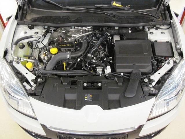
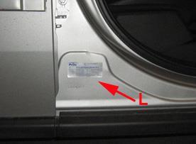

9 PAGE 8 076/ D DLM-2.1 component location overview HPP pump Petrol ECU FSU Fuse / relay box FRU AFC Boost pump R115 approval sticker : Right side centre door post R115

 Also apply engine oil to the groove on the location where the protrusion (C) is installed.")
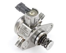
10 PAGE 9 076/ D -INSTALLATION- Installation of the Bosch High Pressure Petrol Pump Before installing the high pressure fuel pump, position the roller tappet ( B&C ) in the lowest position by rotating the crankshaft. Otherwise the installation bolts may be broken because of tension of the pump spring. Apply engine oil to the O-ring (A) of the high pressure fuel pump, the roller tappet (B), and the protrusion (C). ( roller tappet, only if removed from cylinder head ) Also apply engine oil to the groove on the location where the protrusion (C) is installed. Installation bolts: When tightening the installation bolts of the high pressure fuel pump, tighten and turn the bolts in small step ( 0.5 turns ) after tightening them with hand-screwed torque. High pressure petrol pump installation bolt: 12.8 ~ 14.7 N.m Petrol pipe: First hand-tighten the nut(s) fully until they are not fastened any more in order to have them inserted in place and then completely tighten to the specified torque using a torque wrench. If not tightening the bolts or nuts in a straight line with the mating bolt holes or fittings, it may cause a fuel leak due to broken threads. Mount the new fuel line free of tension. High pressure petrol pipe installation nut: 26.5 ~ 32.4 N.m Installation is reverse of removal. It s possible that the new high pressure pump has another thickness of the mounting plate. This deviation in thickness needs your attention and requires an adaption of the mounting bolts. When the new mounting plate has the same thickness as the original, use the original bolts. When the new mounting plate is thicker as the original, use the longer supplied bolts and when the new mounting plate is thinner as the original plate use the shorter supplied bolts. Always check if the new high pressure pump is mounted properly!!


11 PAGE / D High pressure pump / Fuel line installation Replace the High Pressure Pump. Replace the Fuel Line between HP pump and petrol injector rail. For easier mounting of the new fuel line, remove the throttle body. Mount the new fuel line between HP pump and petrol injector rail. Mount the new fuel line free of tension. If the fuel line does not fit correctly, adapt the fuel line. Mount the new fuel line between HP pump and petrol injector rail.


12 PAGE / D Fuel line installation 2 / Connector. Mount the fuel line support bracket with clamp to the fuel line. Mount bracket onto engine, also free of tension. Extend the original wiring by cutting of the original connector. Extend the wiring and connect the new connector. Connect pin 1 from the old connector to pin 1 from the new connector. Mount connector to new HP pump.


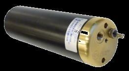
13 PAGE / D Mounting boost pump Mount boost pump clamp on bracket. Mount boost pump in clamp with rubber ring in between. Mount bracket to vehicle below battery on 2 original bolts. Mount bracket to vehicle below battery on 2 original bolts with big washers, spring washers and nuts.


")

14 PAGE / D Connection of the fuel hose to the boost pump. Remove original fuel line to HP pump. Mount adapter to original connection. Mount adapter to original connection. Mount fuel line (blue arrows) from adapter to the boost pump. Mount the fuel line (blue arrows) from the adapter to the boost pump. Use a banjo with filter (black) to connect the fuel line to the boost pump.
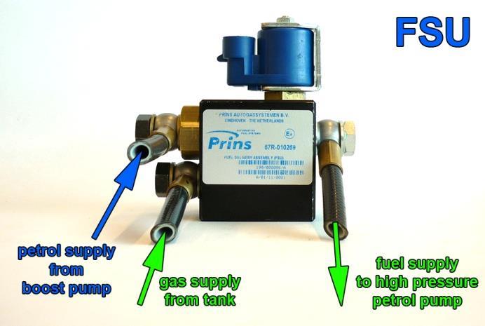
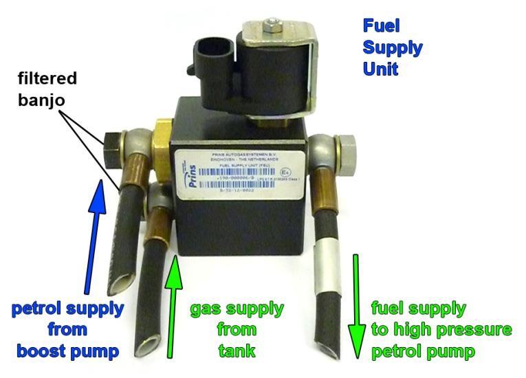
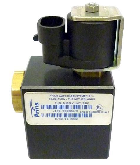
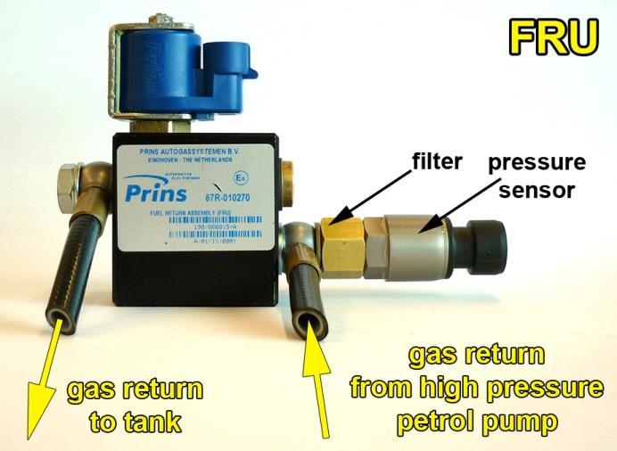
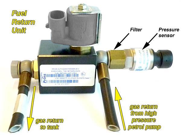
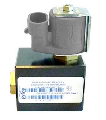
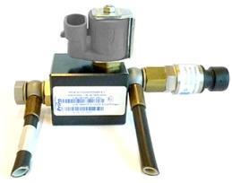
15 PAGE / D Fuel Supply Unit / Fuel Return Unit Black filtered banjo will only be used on inlet connections! Filter inside sensor banjo


16 PAGE / D Mounting the FSU / FRU Mount the FSU / FRU to the bracket. Mount the bracket with FSU / FRU to vehicle with M6 bolts, (spring)washers, and nuts.
 1 XD-3")


17 PAGE / D LPG / petrol fuel lines Hose / size from to Length ( cm ) 1 XD-3 Adapter original petrol hose Petrol boost pump XD-3 Petrol boost pump Fuel supply unit 30 3 XD-3 Fuel supply unit High pressure petrol pump XD-3 Fuel return unit High pressure petrol pump Install the fuel line using two bonded seal washers and banjo bolt : Filtered banjo: ( FSU supply inlets / boost pump inlet / HPP pump inlet : black filtered banjo ) :


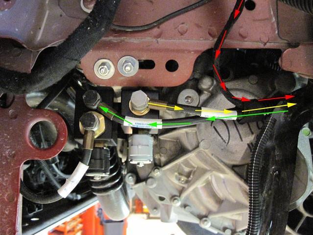
18 PAGE / D Hose routing Boost pump / FSU / FRU - 1 Mount hose from boost pump to FSU. Mount hoses from FSU / FRU to HP pump. Mount hoses from FSU / FRU to HP pump. Mount adapter to HP pump. Mount hoses to HP pump.

.")
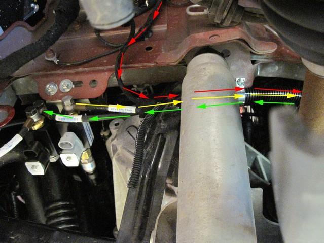
19 PAGE / D Hose routing Boost pump / FSU / FRU - 2 Mount fuel line support bracket to throttle body with original bots. Use clamp to fixate fuel lines (all three lines). Overview fuel lines.

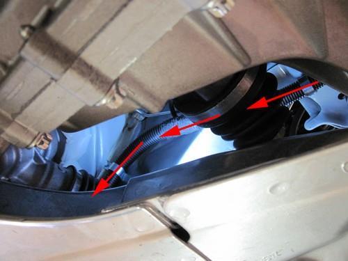
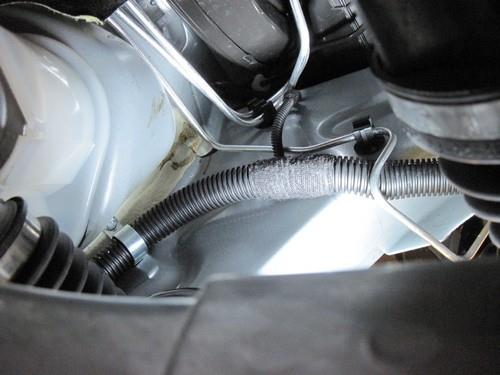
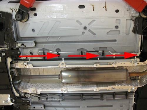
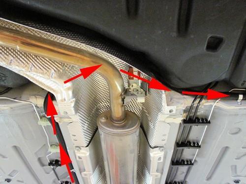
20 PAGE / D Supply hose Return hose Tank wiring Protect the supply- and return hose together with tank-wiring using the Ø16 split tube. Mount the hose assembly with clamps, with a maximum distance of 40cm.
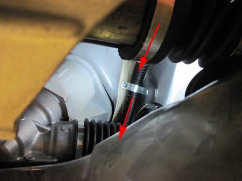
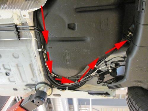
21 PAGE / D Hose / wiring routing to tank - 1 Pull out wiring for wake-up, switch, CAN & fused +Battery.
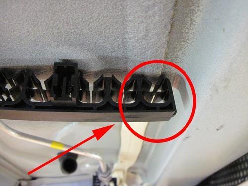
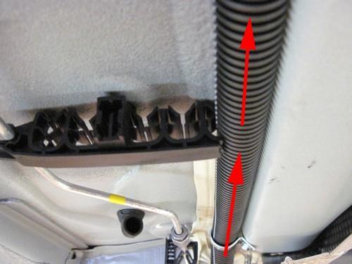
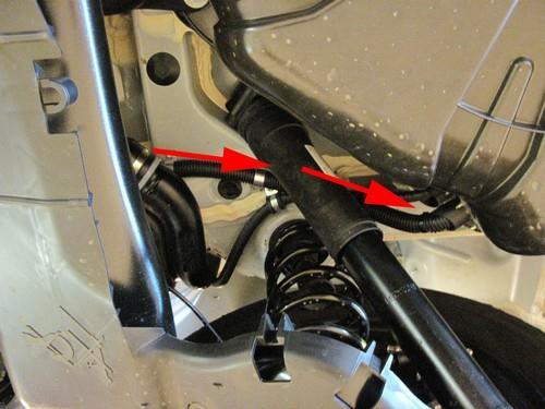
22 PAGE / D Hose / wiring routing to tank - 2 Cut off original clamps where necessary.


23 PAGE / D Mounting the AFC Mount bracket to original threaded rods. Mount plastic AFC-clip to bracket with quick clips. Mount the AFC.

24 PAGE / D Wiring routing AFC


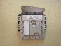
25 PAGE / D Fuse/Relais box & diagnostic connector Bracket for fuse/relais box. Mount bracket to original bolt from left head light. Mount bracket to original bolt from left head light. Mount the box on the bracket. Mount diagnostic connector to cap from box with a cable tie. For transferring the box from the AFC to the engine room, lift up fuse box by removing the 2 bolts (see picture).
.")


26 PAGE / D Grommet / wiring transit Cut away foam under dashboard (see pictures). Mark hole for drilling. Drill hole Ø10mm and treat anti rust. Mount grommet. Put wiring through grommet from underneath the car and use a silicone sealant around wiring for a waterproof transit. Wiring to passenger room: Switch / CAN / Wake-up / Fused +batt.


27 PAGE / D Mounting the fuel selection switch / CAN / Wake-up To connect wake-up, remove control ECU below dashboard on drivers side. EOBD connector for CAN. Space for switch Drill hole 8,3mm for mounting switch. Mount switch with supplied sticker.


28 PAGE / D Connecting the fuel gauge reset module 1 The fuel gauge reset module is mounted underneath the back seat. Connect extension wire to wire nr. 4 at AFC connector. Stab wiring together with Switch / CAN / Wake-up through grommet. Wiring routing through car. Mount 4.5mm split tube around extension wire. Wiring routing. Remove cover.


29 PAGE / D Connecting the fuel gauge reset module 2 Mount foam around reset module and connect wires to wiring of the fuel tank. The reset module will be positioned underneath the black cover on top of the fuel pump/tank gauge. Position 1: White / Position 2: Tan / Position 3: Black / Position 4: Brown Connect wires to the wiring of the fuel tank and mount back covers and back seat.


")

30 PAGE / D Actuator resistance Cut wire from big black connector, Q4, white and connect extension wires. Mount resistor on bracket with 2x M3 screws and spring washers. Solder extension cables to resistor (also use shrink sleeves) and mount bracket to original battery mounting. Wiring routing. Remove flap from petrol ECU cover to fit.


")
31 PAGE / D Petrol ECU pinning If you have to count from A to Q on the connectors, remember: there is no letter i on the connector. Connector 1 (grey) Connector 2 (black) Connector 3 (black)


32 PAGE / D Electrical connections Check and measure the wiring in case of changes in the cars wiring colours. Insulate not used wires. Driver room / inside Wire number / code Wire colour Connection 3-pole micro connector 66 Ground fuel switch 3 +12V fuel switch 49 LIN fuel switch Brown-black Red-white Yellow Connect the 3-pole connector to the Prins fuel selection switch. 51 CAN-High Yellow EOBD connector pin 6 70 CAN-Low Green EOBD connector pin Wake-up Inside! Red-grey Car wake-up Wire colour : pink Wire location : C21 (control ECU below dashboard, see picture) See page 27
 ; use a ring terminal.")
33 PAGE / D Electrical connections Check and measure the wiring in case of changes in the cars wiring colours. Insulate not used wires MAIN GND ecu MAIN GROUND SENSE Brown Connect to the ' ' of the battery ( -31 ) ; use a ring terminal. Wire location : ground on battery V BATT sense +12V BATT fused +12V BATT boost pump +12V BATT pump driver Red Connect to the '+' of the battery ( +30 ); use a ring terminal. Do not place the fuse in the holder before having completed the installation of the lpg system. Wire location : +Batt on battery (see picture above)
34 PAGE / D Electrical connections Check and measure the wiring in case of changes in the cars wiring colours. Insulate not used wires. Wire number / code Wire colour Connection 36&25 High pressure petrol sensor signal interruption Wire colour : pink-black Wire location : Connector 2 petrol ECU F3 36 AD 6 Blue-brown Sensor side 25 DAC 1 Green-white Petrol ecu side 63 Ground Shift Blue-orange 60 DI3 Grey-red 8 RPM engine speed Purple-white 15 T-ect Grey 18 AD 1 Blue-white 7 +12V IGNITION Grey - white High pressure petrol sensor ground Wire colour : purple Wire location : Connector 2 petrol ECU J3 High pressure petrol sensor 5Volt supply Wire colour : white Wire location : Connector 2 petrol ECU J1 For measuring the engine speed signal. Wire colour : pink-black Wire location : Connector 2 petrol ECU D2 For measuring the engine coolant temperature. Wire colour : green-red Wire location : Connector 2 petrol ECU G4 For measuring the inlet manifold pressure from the MAP sensor Wire colour : green-black Wire location : Connector 1 petrol ECU B2 Make a connection to +ignition / contact+ ( +15 ). Do not place the fuses in the holder before having completed the installation of the lpg system. Wire colour : yellow Wire location : Connector 3 petrol ECU D1 2-core wire from actuator resistor See page 29 Wire colour : White Wire location : Connector 2 petrol ECU interrupt wire Q4 and connect the 2 resistor wires. Both ways possible.
35 PAGE / D Electrical connections Check and measure the wiring in case of changes in the cars wiring colours. Insulate not used wires. Wire number / code Wire colour 10 DAC 2 Green insulate 17 AD 2 Blue-green insulate 19 AD 4 Blue insulate 20 AD 3 Blue-pink insulate 21 AD 9 Blue-purple insulate 22 LSS 1 Purple-white insulate 23 LSS 2 Purple-green insulate 42 Digital out pull up 2 Red-purple insulate 56 DI 2 Yellow-green insulate V switched Red-white insulate 61 DI4 Yelow-blue insulate 74 DAC 3 Green-pink Insulate Insulate additional loose wires!


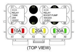
36 PAGE / D Electrical connections Check and measure the wiring in case of changes in the cars wiring colours. Insulate not used wires. Engine room Wire number / code Wire colour Connection 3-pole connector 35 Ground Psys pin A 9 +5V sensor pin B 16 Psys pin C Brown Red-blue Green Connect the 3-pole connector to the Psys sensor positioned into the Fuel Return Unit. Sensor wire pin A Sensor wire pin B Sensor wire pin C 2-pole connector FSU, black 24 + Lock-off FSU 31 C Ground 2-pole connector FRU, grey 43 + Lock-off FRU 34 C Ground 4-pole diagnose connector 46 Service TxD 65 Service RxD 68 C Ground Boost pump relay 2 + relay boost pump 26 Ground BP relay +12V fused BATT +12V Boost pump Wiring tank pump driver relay 57 + driver relay 73 LSS 4 tank relay +12V BATT fused +12V driver Yellow-green Brown-black Red-white Brown-black Grey Grey Brown-black Red-white Purple-blue Red 2.5mm2 Red 2.5mm2 Red-white Purple-blue Red 2.5mm2 Red 2.5mm2 Connect the 2-pole connector to the lock-off valve of the Fuel Supply Unit Connect the 2-pole connector to the lock-off valve of the Fuel Return Unit Diagnose connector for service / diagnosis Connector pin 1 Connector pin 2 Connector pin 4 Pin 86 of the boost pump relay C4 Pin 85 of the boost pump relay B6 Pin 30 of the boost pump relay C6-A5 Pin 87 of the boost pump relay B4 Pin 86 of the driver relay C1 Pin 85 of the driver relay B2 Pin 30 of the driver relay C2-A4 Pin 87 of the driver relay B1 Boost pump connection options:

37 PAGE / D Electrical connections Check and measure the wiring in case of changes in the cars wiring colours. Insulate not used wires. Lpg tank housing Wire number / code Wire colour Connection 3-pole tank level connector 33 Ground tank gauge 12 Tank level in 11 + tank level supply Brown-black Blue Red-blue Connect the 3-pole connector to the tank level sensor. 2-pole driver connector 71 LSS 3 PWM driver 64 AD 5 driver diagnose Purple-pink Blue-grey Connect the 2-pole connector to the pump driver (4) pole connector tank lock-off Green-yellow Brown 2. 3-pole connector tank pump Red 2.5mm 2 Brown 2.5mm pole connector power driver Red 2.5mm 2 Brown 2.5mm pole connector driver Green Grey From tank pump driver From tank pump driver From tank pump driver From tank pump driver From tank pump relay From main ground From AFC pin 71 pwm From AFC pin 64 diagnose
38 PAGE / D Checklist after installation 1. Install the system fuses. Turn on ignition. Connect the Prins interface wire and run the Prins diagnosis program. When working on the car, beware of moving and rotating parts in the engine compartment ( even when the engine is not running!! ). 2. When commissioning the LPG system, you must activate the AFC with the diagnosis software. 3. Check whether the program in the AFC matches with the car ( dedicated engine set ): See Identification in the diagnosis program. 4. Check all components and connections for any LPG leakage, use a LPG leak detector device or a fluid detection like soap. Also check for petrol leakage. Make sure the solenoid valves are in open position. No evidence of leakage is permitted. Caution for moving and rotating parts in the engine compartment! 5. Use the diagnosis software to check again all input and output signals. 6. Check the system for error codes and solve these, if required. Check the petrol MMS for EOBD error codes. Place the protection connector back on the diagnose connector. 7. Make a test drive and check the cars drivability on LPG and petrol.
ENGINE DISPLACEMENT NUMBER OF VALVES 16 VEHICLE CATEGORIES
 MANUFACTURER Dacia TYPE Duster ENGINE DISPLACEMENT 1200cc NUMBER OF VALVES 16 ENGINE CODE / NUMBER H5F (TCe125) VEHICLE CATEGORIES M TRANSMISSION MT (6-speed) VERSION AFC-2.1 PETROL ECU MANUFACTURER /
ENGINE DISPLACEMENT 2000 NUMBER OF VALVES 16 ENGINE SET NUMBER
 MANUFACTURER Subaru TYPE Forester ENGINE DISPLACEMENT 2000 NUMBER OF VALVES 16 ENGINE CODE / NUMBER FA20 DIT VEHICLE CATEGORIES M TRANSMISSION AT VERSION Direct LiquiMax-2.1 PETROL ECU MANUFACTURER / CODE
ENGINE DISPLACEMENT NUMBER OF VALVES ENGINE SET NUMBER VEHICLE CATEGORIES. Direct LiquiMax-2.0 PETROL ECU MANUFACTURER / CODE Bosch MED 17.
 MANUFACTURER VOLVO TYPE V60 / V70 T4F ENGINE DISPLACEMENT 1600cc NUMBER OF VALVES 16v ENGINE CODE / NUMBER B4164T2 VEHICLE CATEGORIES M TRANSMISSION MT/AT VERSION Direct LiquiMax-2.0 PETROL ECU MANUFACTURER
MANUFACTURER Explorer Sport ENGINE DISPLACEMENT NUMBER OF VALVES FIRING ORDER VEHICLE CATEGORIES TRANSMISSION
 MANUFACTURER Ford TYPE Explorer Sport ENGINE DISPLACEMENT 3500cc NUMBER OF VALVES 24v ENGINE CODE / NUMBER 3.5L GTDi Ecoboost FIRING ORDER 1 4 2 5-3 - 6 VEHICLE CATEGORIES M TRANSMISSION AT VERSION AFC-2.1
MANUFACTURER TYPE F-150 ENGINE DISPLACEMENT NUMBER OF VALVES FIRING ORDER VEHICLE CATEGORIES TRANSMISSION
 MANUFACTURER Ford TYPE F-150 ENGINE DISPLACEMENT 3500cc NUMBER OF VALVES 24v ENGINE CODE / NUMBER - OUTPUT 3.5L EcoBoost 2015 365hp FIRING ORDER 1-4-2-5-3-6 VEHICLE CATEGORIES M TRANSMISSION AT VERSION
MAKE OF AUTOMOBILE: TYPE: 508 PISTON DISPLACEMENT: NUMBER OF VALVES: FIRING ORDER: TRANSMISSION TYPE ( MT / AT ) VEHICLE CATEGORIES M or N
 VEHICLE CATEGORIES M or N") MAKE OF AUTOMOBILE: Peugeot TYPE: 508 PISTON DISPLACEMENT: 1600cc NUMBER OF VALVES: 16v ENGINE NUMBER: EP6CDT 115kW FIRING ORDER: 1-3-4-2 TRANSMISSION TYPE ( MT / AT ) MT VEHICLE CATEGORIES M or N M TYPE
MAKE OF AUTOMOBILE: Peugeot TYPE: 508 PISTON DISPLACEMENT: 1600cc NUMBER OF VALVES: 16v ENGINE NUMBER: EP6CDT 115kW FIRING ORDER: 1-3-4-2 TRANSMISSION TYPE ( MT / AT ) MT VEHICLE CATEGORIES M or N M TYPE
MODEL YEAR: 2010 SYSTEM APPROVAL NUMBER ( R115 ) R ENGINE SET NUMBER 349/ (.06 /.07 )
 R ENGINE SET NUMBER 349/ (.06 /.07 )") MAKE OF AUTOMOBILE: TYPE: IX35 PISTON DISPLACEMENT: 2000 NUMBER OF VALVES: 16 ENGINE NUMBER: G4KD TRANSMISSION TYPE ( MT / AT ) MT VEHICLE CATEGORIES M or N M TYPE VSI INJECTOR ( COLOUR ) Orange VERSION
MAKE OF AUTOMOBILE: TYPE: IX35 PISTON DISPLACEMENT: 2000 NUMBER OF VALVES: 16 ENGINE NUMBER: G4KD TRANSMISSION TYPE ( MT / AT ) MT VEHICLE CATEGORIES M or N M TYPE VSI INJECTOR ( COLOUR ) Orange VERSION
PISTON DISPLACEMENT: NUMBER OF VALVES: 16. TRANSMISSION TYPE ( MT / AT ) VEHICLE CATEGORIES M or N TYPE VSI INJECTOR ( COLOUR ) VERSION ( LPG / CNG )
 VEHICLE CATEGORIES M or N TYPE VSI INJECTOR ( COLOUR ) VERSION ( LPG / CNG )") MAKE OF AUTOMOBILE: TYPE: Ram PISTON DISPLACEMENT: 5700cc NUMBER OF VALVES: 16 ENGINE NUMBER: 5.7V8 Hemi 290kW TRANSMISSION TYPE ( MT / AT ) AT VEHICLE CATEGORIES M or N M TYPE VSI INJECTOR ( COLOUR )
MAKE OF AUTOMOBILE: TYPE: Ram PISTON DISPLACEMENT: 5700cc NUMBER OF VALVES: 16 ENGINE NUMBER: 5.7V8 Hemi 290kW TRANSMISSION TYPE ( MT / AT ) AT VEHICLE CATEGORIES M or N M TYPE VSI INJECTOR ( COLOUR )
MAKE OF AUTOMOBILE: MODEL YEAR: 2004 SYSTEM APPROVAL NUMBER ( R115 ) ENGINE SET NUMBER 336/
 ENGINE SET NUMBER 336/") MAKE OF AUTOMOBILE: TYPE: A4 PISTON DISPLACEMENT: 1800 NUMBER OF VALVES: 20V ENGINE NUMBER: BFB TRANSMISSION TYPE ( MT / AT ) AT VEHICLE CATEGORIES M or N M TYPE VSI INJECTOR ( NUMBER + COLOR ) YELLOW
MAKE OF AUTOMOBILE: TYPE: A4 PISTON DISPLACEMENT: 1800 NUMBER OF VALVES: 20V ENGINE NUMBER: BFB TRANSMISSION TYPE ( MT / AT ) AT VEHICLE CATEGORIES M or N M TYPE VSI INJECTOR ( NUMBER + COLOR ) YELLOW
MAKE OF AUTOMOBILE: MODEL YEAR: 2007 SYSTEM APPROVAL NUMBER ( R115 ) R ENGINE SET NUMBER 349/
 R ENGINE SET NUMBER 349/") MAKE OF AUTOMOBILE: KIA TYPE: CARENS PISTON DISPLACEMENT: 2000 NUMBER OF VALVES: 16 ENGINE NUMBER: G4KA TRANSMISSION TYPE ( MT / AT ) MT VEHICLE CATEGORIES M or N M TYPE VSI INJECTOR ( COLOUR ) ORANGE
MAKE OF AUTOMOBILE: KIA TYPE: CARENS PISTON DISPLACEMENT: 2000 NUMBER OF VALVES: 16 ENGINE NUMBER: G4KA TRANSMISSION TYPE ( MT / AT ) MT VEHICLE CATEGORIES M or N M TYPE VSI INJECTOR ( COLOUR ) ORANGE
MAKE OF AUTOMOBILE: ENGINE SET NUMBER 348/
 MAKE OF AUTOMOBILE: TYPE: CIVIC PISTON DISPLACEMENT: 1800 NUMBER OF VALVES: 16 ENGINE NUMBER: R18A TRANSMISSION TYPE ( MT / AT ) MT VEHICLE CATEGORIES M or N M TYPE VSI INJECTOR ( COLOR ) ORANGE VERSION
PISTON DISPLACEMENT: 1200 NUMBER OF VALVES: ENGINE NUMBER: TRANSMISSION TYPE ( MT / AT ) VEHICLE CATEGORIES M or N TYPE VSI INJECTOR (COLOUR )
 VEHICLE CATEGORIES M or N TYPE VSI INJECTOR (COLOUR )") MAKE OF AUTOMOBILE: VOLKSWAGEN TYPE: POLO PISTON DISPLACEMENT: 1200 NUMBER OF VALVES: 8V ENGINE NUMBER: BZG TRANSMISSION TYPE ( MT / AT ) MT VEHICLE CATEGORIES M or N M TYPE VSI INJECTOR (COLOUR ) BLUE
MAKE OF AUTOMOBILE: VOLKSWAGEN TYPE: POLO PISTON DISPLACEMENT: 1200 NUMBER OF VALVES: 8V ENGINE NUMBER: BZG TRANSMISSION TYPE ( MT / AT ) MT VEHICLE CATEGORIES M or N M TYPE VSI INJECTOR (COLOUR ) BLUE
Required equipment / tools / materials for installing a complete system. Vehicle check
 2-2017 Table of contents Required equipment / tools / materials for installing a complete system 3 Vehicle check 3 General instructions 4 Tightening moments 5 Direct LiquiMax Gen1 & Gen2 components 6 Approval
MAKE OF AUTOMOBILE: TYPE: V 70 PISTON DISPLACEMENT: 2521 NUMBER OF VALVES:
 MAKE OF AUTOMOBILE: TYPE: V 70 PISTON DISPLACEMENT: 2521 NUMBER OF VALVES: 20V ENGINE NUMBER: B5254T TRANSMISSION TYPE ( MT / AT ) AT VEHICLE CATEGORIES M or N PASSENGER CAR ( M ) TYPE VSI INJECTOR (COLOUR
MAKE OF AUTOMOBILE: PISTON DISPLACEMENT: 1300
 MAKE OF AUTOMOBILE: TYPE: YARIS PISTON DISPLACEMENT: 1300 NUMBER OF VALVES: 16 VVT-I ENGINE NUMBER: 2SZ-FE TRANSMISSION TYPE ( MT / AT ) AT VEHICLE CATEGORIES M or N M TYPE VSI INJECTOR ( NUMBER + COLOR
MAKE OF AUTOMOBILE: 316 / 318i E46 NUMBER OF VALVES:
 MAKE OF AUTOMOBILE: TYPE: 316 / 318i E46 PISTON DISPLACEMENT: 1800 2000 cc NUMBER OF VALVES: 16V ENGINE NUMBER: N42B18A / N42B20A TRANSMISSION TYPE ( MT / AT ) MT VEHICLE CATEGORIES M or N M TYPE VSI INJECTOR
MAKE OF AUTOMOBILE: ENGINE SET NUMBER 366/
 MAKE OF AUTOMOBILE: TYPE: SORENTO PISTON DISPLACEMENT: 3300 NUMBER OF VALVES: 24 ENGINE NUMBER: G6DB TRANSMISSION TYPE ( MT / AT ) MT VEHICLE CATEGORIES M or N M TYPE VSI INJECTOR ( NUMBER + COLOR ) 180/30340
MAKE OF AUTOMOBILE: MODEL YEAR: 2007 SYSTEM APPROVAL NUMBER ( R115 ) VSI-LPG 10 ENGINE SET NUMBER 364/
 VSI-LPG 10 ENGINE SET NUMBER 364/") MAKE OF AUTOMOBILE: TYPE: FABIA PISTON DISPLACEMENT: 1400 NUMBER OF VALVES: 16 ENGINE NUMBER: BUD TRANSMISSION TYPE ( MT / AT ) MT VEHICLE CATEGORIES M or N M TYPE VSI INJECTOR ( NUMBER + COLOR ) 180/30410
MAKE OF AUTOMOBILE: TYPE: FABIA PISTON DISPLACEMENT: 1400 NUMBER OF VALVES: 16 ENGINE NUMBER: BUD TRANSMISSION TYPE ( MT / AT ) MT VEHICLE CATEGORIES M or N M TYPE VSI INJECTOR ( NUMBER + COLOR ) 180/30410
MODEL YEAR: 2009 SYSTEM APPROVAL NUMBER ( R115 ) R ENGINE SET NUMBER 350/
 R ENGINE SET NUMBER 350/") MAKE OF AUTOMOBILE: TYPE: PRIORA 2170 / 2172 PISTON DISPLACEMENT: 1600 NUMBER OF VALVES: 16 ENGINE NUMBER: 21126 TRANSMISSION TYPE ( MT / AT ) MT VEHICLE CATEGORIES M or N M TYPE VSI INJECTOR (COLOR )
MAKE OF AUTOMOBILE: TYPE: PRIORA 2170 / 2172 PISTON DISPLACEMENT: 1600 NUMBER OF VALVES: 16 ENGINE NUMBER: 21126 TRANSMISSION TYPE ( MT / AT ) MT VEHICLE CATEGORIES M or N M TYPE VSI INJECTOR (COLOR )
MODEL YEAR: SYSTEM APPROVAL NUMBER ( R115 ) R ENGINE SET NUMBER 354/
 R ENGINE SET NUMBER 354/") MAKE OF AUTOMOBILE: MERECEDES TYPE: E200 W211 PISTON DISPLACEMENT: 1796 NUMBER OF VALVES: 16 ENGINE NUMBER: M271 TRANSMISSION TYPE ( MT / AT ) AT VEHICLE CATEGORIES M or N M TYPE VSI INJECTOR ( NUMBER
MAKE OF AUTOMOBILE: MERECEDES TYPE: E200 W211 PISTON DISPLACEMENT: 1796 NUMBER OF VALVES: 16 ENGINE NUMBER: M271 TRANSMISSION TYPE ( MT / AT ) AT VEHICLE CATEGORIES M or N M TYPE VSI INJECTOR ( NUMBER
MODEL YEAR: 2007 SYSTEM APPROVAL NUMBER ( R115 ) R ENGINE SET NUMBER 350/
 R ENGINE SET NUMBER 350/") MAKE OF AUTOMOBILE: TYPE: KALINA 1117/ 1118 / 1119 PISTON DISPLACEMENT: 1600 NUMBER OF VALVES: 8 ENGINE NUMBER: 21114 TRANSMISSION TYPE ( MT / AT ) MT VEHICLE CATEGORIES M or N M TYPE VSI INJECTOR ( NUMBER
MAKE OF AUTOMOBILE: TYPE: KALINA 1117/ 1118 / 1119 PISTON DISPLACEMENT: 1600 NUMBER OF VALVES: 8 ENGINE NUMBER: 21114 TRANSMISSION TYPE ( MT / AT ) MT VEHICLE CATEGORIES M or N M TYPE VSI INJECTOR ( NUMBER
MAKE OF AUTOMOBILE: PISTON DISPLACEMENT: 8300 NUMBER OF VALVES: 20 TRANSMISSION TYPE ( MT / AT ) TYPE VSI INJECTOR (COLOR ) VERSION ( LPG / CNG )
 TYPE VSI INJECTOR (COLOR ) VERSION ( LPG / CNG )") MAKE OF AUTOMOBILE: TYPE: PISTON DISPLACEMENT: 8300 NUMBER OF VALVES: 20 ENGINE NUMBER: SRT V10 Viper TRANSMISSION TYPE ( MT / AT ) AT TYPE VSI INJECTOR (COLOR ) YELLOW VERSION ( LPG / CNG ) LPG INJECTION
MAKE OF AUTOMOBILE: TYPE: PISTON DISPLACEMENT: 8300 NUMBER OF VALVES: 20 ENGINE NUMBER: SRT V10 Viper TRANSMISSION TYPE ( MT / AT ) AT TYPE VSI INJECTOR (COLOR ) YELLOW VERSION ( LPG / CNG ) LPG INJECTION
MAKE OF AUTOMOBILE: PISTON DISPLACEMENT: 2700 NUMBER OF VALVES:
 MAKE OF AUTOMOBILE: DODGE TYPE: JOURNEY PISTON DISPLACEMENT: 2700 NUMBER OF VALVES: 24V ENGINE NUMBER: 2.7V6 EER TRANSMISSION TYPE ( MT / AT ) AT VEHICLE CATEGORIES M or N M TYPE VSI INJECTOR ( COLOR )
MAKE OF AUTOMOBILE: GRAND CHEROKEE PISTON DISPLACEMENT: 5700 NUMBER OF VALVES: 16
 MAKE OF AUTOMOBILE: TYPE: GRAND CHEROKEE PISTON DISPLACEMENT: 5700 NUMBER OF VALVES: 16 ENGINE NUMBER: 5.7V8 HEMI TRANSMISSION TYPE ( MT / AT ) AT VEHICLE CATEGORIES M or N M TYPE VSI INJECTOR ( NUMBER
MAKE OF AUTOMOBILE: ENGINE SET NUMBER 337/
 MAKE OF AUTOMOBILE: TYPE: NITRO PISTON DISPLACEMENT: 3700 NUMBER OF VALVES: 12V ENGINE NUMBER: V6 TRANSMISSION TYPE ( MT / AT ) AT VEHICLE CATEGORIES M or N M TYPE VSI INJECTOR ( NUMBER + COLOR ) 180/30330
MAKE OF AUTOMOBILE: NUMBER : 076/ DATE : Copyright Prins Autogassystemen B.V VERSION NR : B
 MAKE OF AUTOMOBILE: Ford TYPE: Mondeo PISTON DISPLACEMENT: 2000 NUMBER OF VALVES: 16 ENGINE NUMBER: AOBA TYPE VSI INJECTOR ( COLOR ) Yellow MODEL YEAR: 2010 ENGINE SET NUMBER 347/1810500.07 NUMBER : 076/0703201
Prins autogassystemen b.v. Veldhoven
 Prins autogassystemen b.v. Veldhoven MOUNTING INSTRUCTION ENGINE CONVERSION SET MAKE OF AUTOMOBILE: TYPE: ASTRA PISTON DISPLACEMENT: 2000 cc MT NUMBER OF VALVES: 16V ENGINE NUMBER: X20XEV INJECTION SYSTEM:
Universal instructions CNG Tank-sets. MODEL year 2011 SET Number. NUMMER : DATE : Copyright Prins Autogassystemen B.V VERSIE NR : DB
 Universal instructions CNG Tank-sets Make universal MODEL year 2011 SET Number all NUMMER : DATE : 2011-09-12 TABLE OF CONTENTS... 1 Required equipment / tools / materials for installing a complete system...
MAKE OF AUTOMOBILE: ENGINE SET NUMBER 345/ NUMBER : 076/ DATE : VERSION NR : B
 MAKE OF AUTOMOBILE: TYPE: LOGAN PISTON DISPLACEMENT: 1600 NUMBER OF VALVES: 8 ENGINE NUMBER: K7M 710 TRANSMISSION TYPE ( MT / AT ) MT VEHICLE CATEGORIES M or N ( M ) TYPE VSI INJECTOR ( NUMBER + COLOR
MAKE OF AUTOMOBILE: MODEL YEAR: SYSTEM APPROVAL NUMBER ( R115 ) E4-115R /-17 / DLM-LPG 01/10 MANUAL NUMBER: 076/ DATE
 E4-115R /-17 / DLM-LPG 01/10 MANUAL NUMBER: 076/ DATE") MAKE OF AUTOMOBILE: HYUNDAI TYPE: ix35 TANK CAPACITY: 74 Liter Fuel Module Stako toroidal TANK LOCATION SPARE WHEEL ROOM MODEL YEAR: 2010 SYSTEM APPROVAL NUMBER ( R115 ) E4-115R-0000-04/-17 / DLM-LPG 01/10
MAKE OF AUTOMOBILE: HYUNDAI TYPE: ix35 TANK CAPACITY: 74 Liter Fuel Module Stako toroidal TANK LOCATION SPARE WHEEL ROOM MODEL YEAR: 2010 SYSTEM APPROVAL NUMBER ( R115 ) E4-115R-0000-04/-17 / DLM-LPG 01/10
MAKE OF AUTOMOBILE: PISTON DISPLACEMENT: NUMBER OF VALVES: ENGINE NUMBER: TRANSMISSION TYPE ( MT / AT ) VEHICLE CATEGORIES M or N PERSONEN AUTO ( M )
 VEHICLE CATEGORIES M or N PERSONEN AUTO ( M )") MAKE OF AUTOMOBILE: TYPE: WRANGLER PISTON DISPLACEMENT: 4000 cc NUMBER OF VALVES: 12 v ENGINE NUMBER: M3 TJ TRANSMISSION TYPE ( MT / AT ) MT VEHICLE CATEGORIES M or N PERSONEN AUTO ( M ) TYPE VSI INJECTOR
MAKE OF AUTOMOBILE: TYPE: WRANGLER PISTON DISPLACEMENT: 4000 cc NUMBER OF VALVES: 12 v ENGINE NUMBER: M3 TJ TRANSMISSION TYPE ( MT / AT ) MT VEHICLE CATEGORIES M or N PERSONEN AUTO ( M ) TYPE VSI INJECTOR
MAKE OF AUTOMOBILE: MODEL YEAR: 2013 SYSTEM APPROVAL NUMBER ( R115 ) R MANUAL NUMBER: 076/ DATE
 R MANUAL NUMBER: 076/ DATE") MAKE OF AUTOMOBILE: Dacia TYPE: Lodgy TANK CAPACITY: 59 Liter Stako toroidal TANK LOCATION Spare Wheel Room / Underneath MODEL YEAR: 2013 SYSTEM APPROVAL NUMBER ( R115 ) R115-000013 BOOT SET NUMBER 345/070002/A
MAKE OF AUTOMOBILE: Dacia TYPE: Lodgy TANK CAPACITY: 59 Liter Stako toroidal TANK LOCATION Spare Wheel Room / Underneath MODEL YEAR: 2013 SYSTEM APPROVAL NUMBER ( R115 ) R115-000013 BOOT SET NUMBER 345/070002/A
MAKE OF AUTOMOBILE: PISTON DISPLACEMENT: 1600 NUMBER OF VALVES: 16
 MAKE OF AUTOMOBILE: TYPE: MERIVA PISTON DISPLACEMENT: 1600 NUMBER OF VALVES: 16 ENGINE NUMBER: Z16XEP TRANSMISSION TYPE ( MT / AT ) MT VEHICLE TYPE M TYPE VSI INJECTOR ( NUMBER + COLOR ) 180/30430 ORANGE
MAKE OF AUTOMOBILE: MODEL YEAR: 2010 SYSTEM APPROVAL NUMBER ( R115 ) BOOT SET NUMBER 947/
 BOOT SET NUMBER 947/") MAKE OF AUTOMOBILE: FORD TYPE: MONDEO TANK CAPACITY: 61 Liter WvM toroidal TANK LOCATION SPARE WHEEL ROOM MODEL YEAR: 2010 SYSTEM APPROVAL NUMBER ( R115 ) R115-0000** BOOT SET NUMBER 947/1810501 NUMBER:
MAKE OF AUTOMOBILE: FORD TYPE: MONDEO TANK CAPACITY: 61 Liter WvM toroidal TANK LOCATION SPARE WHEEL ROOM MODEL YEAR: 2010 SYSTEM APPROVAL NUMBER ( R115 ) R115-0000** BOOT SET NUMBER 947/1810501 NUMBER:
3.4L V6 SUPERCHARGER 7 TH INJECTOR KIT
 Part Number: 00602-17620-260 00602-17620-261 00602-17620-263 00602-17620-264 00602-17620-274 00602-17620-275 00602-17620-276 Section I Installation Preparation Kit Contents Item # Quantity Reqd. Description
DATE : VERSION NR :
 DATE : 07032006 VERSION NR : B Table of contents General instructions 2 Introduction 3 Overview VSI system 4 Approval numbers VSI components 4 The ucer 5 The injector rail 6 The filter unit 7 The VSI computer
Wiring for OMS/Mid-engine layout
 Wiring for OMS/Mid-engine layout Coil connectors Crank sensor Coolant temperature sensor Cam sensor Connector for fuel pump Connector for joining new wiring harness to existing Suzuki wiring will need
Installation Instructions General Motors 8.1 Sequential Vapor Injection (S.V.I.) System 7500/6500 Series Trucks model year.
 System 7500/6500 Series Trucks model year.") Installation Instructions General Motors 8.1 Sequential Vapor Injection (S.V.I.) System 7500/6500 Series Trucks 2003-2005 model year. Technocarb Equipment (2004) Ltd. 4-30435 Progressive Way Abbotsford,
Installation Instructions General Motors 8.1 Sequential Vapor Injection (S.V.I.) System 7500/6500 Series Trucks 2003-2005 model year. Technocarb Equipment (2004) Ltd. 4-30435 Progressive Way Abbotsford,
16A. STARTING - CHARGING Starter: Removal - Refitting REFITTING 16A-11 K4M II - REMOVAL OPERATION III - FINAL OPERATION
 STARTING - CHARGING Starter: Removal - Refitting 16A K4M II - REMOVAL OPERATION III - FINAL OPERATION JR5 a Clip: -the gearbox control cable sleeve stops on the gearbox, - the control cables onto the gearbox.
Nero 6600H/6601H. Installation Guide. Commercial Vehicle Productivity and Security. Antenna Configuration
 Commercial Vehicle Productivity and Security The 6600H/6601H is a versatile and economical GPS tracking beacon designed for fleet management needs in all commercial vehicles. The H designation in the model
MAKE OF AUTOMOBILE: GRAND VOYAGER STOW`N GO MODEL YEAR: NUMBER: 076/ Copyright Prins Autogassystemen B.V DATE:
 MAKE OF AUTOMOBILE: CHRYSLER TYPE: GRAND VOYAGER STOW`N GO TANK CAPACITY: 2X 36Liter Stako toroidal TANK LOCATION FRONT SEAT ROOM MODEL YEAR: NUMBER: 076/3211036 Copyright Prins Autogassystemen B.V. 2008
Weistec M113K Supercharger System Installation Guide
 Weistec M113K Supercharger System Installation Guide WARNING! DO NOT HAVE YOUR ECU REPROGRAMMED ANYWHERE BUT AT WEISTEC FOR THIS SUPERCHARGER. THE AMG 55 USES AN ELECTRONIC THROTTLE CONTROL (ETC), WHICH
Cylinder head, removing and
 Page 1 of 35 15-2 Cylinder head, removing and installing Note: Replace cylinder head bolts. Always replace self-locking nuts, bolts as well as gaskets and O-rings. After installing a replacement cylinder
INSTALLATION AND USER MANUAL
 INSTALLATION AND USER MANUAL SDKIT-730 & SDKIT-734 100% Bolt-On 150 PSI Train Horn System for 2011-2015 F-250 & F-350 Super Duty P/N SDKIT-730 P/N SDKIT-734 Thank you for purchasing a Kleinn Air Horns
REC-11+ REMOTE RECEIVER UNIT
 Resetting The Programmable Features The installer may quickly and easily return all 17 programmable features back to the factory settings. Changing individual features were explained in detail in the previous
Nissan GTR Alpha Fuel System
 Nissan GTR Alpha Fuel System Instructions V5 The goal of AMS is to provide the highest quality, best performing products available. By utilizing research and development, and rigorous testing programs
INSTALLATION INSTRUCTIONS. Revision 4.0.3
 INSTALLATION INSTRUCTIONS Revision 4.0.3 Table of Contents INTRODUCTION... 3 INSTALLATION OVERVIEW... 4 Included Parts... 5 DEVICE WIRING... 6 Required Parts... 6 Guidelines... 6 Wiring Diagram... 7 Engine
VT Commodore LPG installation utilising an LPG Memcal and Apexus Quick-kit.
 VT Commodore LPG installation utilising an LPG Memcal and Apexus Quick-kit. Description of components and operation LPG/Petrol Changeover switch The LPG change-over switch is mounted in the instrument
Designed for the Street Proven on the Track
 TDR Fuel and Timing Card Wiring Thank you for using our TDR Fuel and or Timing Cards (F/T). There are two options on how to wire the F/T cards. Our preferred method is to use our TDR Patch Harness as shown
C FORD F250 / F L POWERSTROKE DIESEL WITH AUTOMATIC TRANSMISSIONS ONLY
 EXHAUST BRAKES C40019 1999-2003 FORD F250 / F350 7.3L POWERSTROKE DIESEL WITH AUTOMATIC TRANSMISSIONS ONLY Getting Started Thank you and congratulations on your purchase of a Pacbrake exhaust retarder.
Fitting Instructions: Street Triple from VIN and Street Triple R from VIN A
 English Fitting Instructions: Street Triple from VIN 560477 and Street Triple R from VIN 560477 A9808113 Thank you for choosing this Triumph genuine accessory kit. This accessory kit is the product of
These instructions were written for reference only and the use of a factory service manual is recommended.
 Introducing the CorkSport High Pressure Fuel Line designed for the MZR DISI. This fuel line is designed to replace the OEM fuel line which are prone to failure at the brazed connection at the rail. The
Fuel injection system, servicing
 24-1 Fuel injection system, servicing Component locations overview 1 - Oxygen sensor 1 before Three Way Catalyst G39 2 - Oxygen sensor 2 after Three Way Catalyst G130 3 - Engine Coolant Temperature sensor
WARNING: ALWAYS relieve fuel pressure before disconnecting any fuel related component. DO NOT allow fuel to contact engine or electrical components.
 4.0L V8 - VINS [K,U] Selected Block 1990 Lexus LS 400 For Lextreme Powertrain 2020 S. Hacienda Blvd. # D Hacienda Heights California 91745 Copyright 1998 Mitchell Repair Information Company, LLC Friday,
Installation instructions
 Service Installation instructions Audi A4/A5 (B8 series) 2008 Engine sound system For scope of delivery 8T0.071.901* Audi Genuine Accessories Service Department. Technical Information Service Contents
2002 ENGINE PERFORMANCE. Self-Diagnostics - RAV4. Before performing testing procedures, check for any related Technical Service Bulletins (TSBs).
.") 2002 ENGINE PERFORMANCE Self-Diagnostics - RAV4 INTRODUCTION NOTE: Before performing testing procedures, check for any related Technical Service Bulletins (TSBs). To properly diagnosis and repair this
2002 ENGINE PERFORMANCE Self-Diagnostics - RAV4 INTRODUCTION NOTE: Before performing testing procedures, check for any related Technical Service Bulletins (TSBs). To properly diagnosis and repair this
LAMBDA SENSOR CONTROLLER
 LAMBDA SENSOR CONTROLLER INSTALLATION & PROGRAMMING MANUAL version : V1.77 -V1.79 Manufacturer: AC Spółka Akcyjna. 15-182 Białystok, ul. 27 Lipca 64, Poland tel. +48 85 7438148, fax +48 85 653 8649 www.ac.com.pl,
Ford 6.7L Powerstroke Positive Air Shutoff
 8 April 2013 Ford 6.7L 2011-2012 Positive Air Shutoff 1 2011-2012 Ford 6.7L Powerstroke Positive Air Shutoff P/N# 1036703 P/N# 1036703-M UPLEASE READ ALL INSTRUCTIONS BEFORE INSTALLATION BD Engine Brake
English. Fitting Instructions: Trophy and Trophy SE A of 12. Parts Supplied:
 English Fitting Instructions: Trophy and Trophy SE A9808015 Thank you for choosing this Triumph genuine accessory kit. This accessory kit is the product of Triumph's use of proven engineering, exhaustive
WORLD LEADER IN ALTERNATIVE FUEL SYSTEMS CALIBRATION PARAMETERS
 WORLD LEADER IN ALTERNATIVE FUEL SYSTEMS CALIBRATION PARAMETERS VSI-2.0 LPG UNIVERSAL KIT Version: Back V2.4 to Parameter 03-2018 Overview Page 1 of 53 Copyright Prins Autogassystemen B.V. 2018 Back to
Congratulations on purchasing the Edge Juice/Attitude system for the Dodge Cummins Diesel.
 Getting Started About the Juice Congratulations on purchasing the Edge Juice/Attitude system for the Dodge Cummins Diesel. The Juice/Attitude system features an intelligent module (Juice) that acts as
HKS ELECTRONICS TECHNOLOGY SLD T6 HKS SPEED LIMIT DEFENCER
 HKS ELECTRONICS TECHNOLOGY SLD T6 HKS SPEED LIMIT DEFENCER INSTRUCTIONS Pursuing the Ultimate in Engine Performance and Efficiency HKS Company Limited 212290 047T 18 th Oct 2000 Ver. 3-1. 02 Introduction
These instructions were written for reference only and the use of a factory service manual is recommended.
 Introducing the CorkSport High Pressure Fuel Line designed for the MZR DISI. This fuel line is designed to replace the OEM fuel line which are prone to failure at the brazed connection at the rail. The
BMW Parts and Accessories Installation Instructions
 BMW Parts and Accessories Installation Instructions 46 77 B BMW subwoofer module retrofit kit BMW 3 Series compact (E 46/5) LHD Technical and electrical knowledge required Installation time approx. 1.5-2.5
DirectMount EXHAUST BRAKES
 DirectMount EXHAUST BRAKES APPLICATION: Fixed Orifice and PRXB Exhaust Brakes 2003 2005 Dodge Trucks with 3.5" & 4" Exhaust and 47RE & 48RE Automatic Transmissions Only Vehicles with an existing air compressor
GM 6.6L (LLY, LZB, LMM) Duramax Positive Air Shutoff 2.5 CAC TUBES
 Duramax Positive Air Shutoff 2.5 CAC TUBES") 8 April 2013 1036712 GM/Chevy Duramax 2004.5-2010 (LLY,LBZ,LMM) Positive Air Shutoff 1 2005-2010 GM 6.6L (LLY, LZB, LMM) Duramax Positive Air Shutoff 2.5 CAC TUBES P/N# 1036712 P/N# 1036712-M UPLEASE READ
8 April 2013 1036712 GM/Chevy Duramax 2004.5-2010 (LLY,LBZ,LMM) Positive Air Shutoff 1 2005-2010 GM 6.6L (LLY, LZB, LMM) Duramax Positive Air Shutoff 2.5 CAC TUBES P/N# 1036712 P/N# 1036712-M UPLEASE READ
G - TESTS W/CODES - 2.2L
 G - TESTS W/CODES - 2.2L 1994 Toyota Celica 1994 ENGINE PERFORMANCE Toyota 2.2L Self-Diagnostics Celica INTRODUCTION If no faults were found while performing F - BASIC TESTING, proceed with self-diagnostics.
Controls Pack Installation Manual 2011 and newer 5.0L 4V and 5.4L 4V Engines
 Please visit www.fordracingparts.com for the most current instruction and warranty information.!!! PLEASE READ ALL OF THE FOLLOWING INSTRUCTIONS CAREFULLY PRIOR TO INSTALLATION. AT ANY TIME YOU DO NOT
= Experienced
 I N S T A L L A T I O N G U I D E APPLICATION LENGTH MODEL YR PART # Ford F-250 / F-350 / F-450 Regular Cab * (48 ) 2002-2003, 2008-2012 75134-01A Ford F-250 / F-350 / F-450 Super Cab * (60 ) 2002-2003,
INSTALLATION INSTRUCTIONS. Revision 3.1.1
 INSTALLATION INSTRUCTIONS Revision 3.1.1 Table of Contents INTRODUCTION... 4 INSTALLATION OVERVIEW... 5 Included Parts... 6 DEVICE WIRING... 7 Required Parts... 7 Guidelines... 7 Wiring Diagram... 8 Compatible
CUMMINS 6.7L EXHAUST BRAKE PRXB EXHAUST BRAKE KIT FOR 2007½-2015 TRUCKS EQUIPPED WITH 6.7L CUMMINS ISB DIESEL ENGINES. C Kit C Kit
 CUMMINS 6.7L EXHAUST BRAKE PRXB EXHAUST BRAKE KIT FOR 2007½-2015 TRUCKS EQUIPPED WITH 6.7L CUMMINS ISB DIESEL ENGINES C44038 4 Kit C44039 5 Kit BEFORE STARTING THE INSTALLATION please read the entire installation
INSTALLATION INSTRUCTIONS
 INSTALLATION INSTRUCTIONS Accessory Application Publications No. AII 36765 S 2008 RIDGELINE Issue Date JUN 2007 PARTS LIST Relay Fog Light Kit P/N 08V31-SJC-100 Right fog light 15 Wire ties Left fog light
INSTALLATION MANUAL. Middle. Def tank. Standard. Middle. Standard. Def tank WARNING. Level of Difficulty CAUTION. Parts List.
 INSTALLATION MANUAL 3025101 Level of Difficulty Moderate This is the second first of two of two manuals required to complete this installation. The first second manual manual is is included with with your
WOC & WOC Top & Back Installation Instructions
 Shown with optional Sun Roof WOC-900500-2 & WOC-900501-2 Top & Back Installation Instructions Install Order! Heater Door System Wiper on to Windshield Windshield Rear Panel Top Panel Tools needed: 5/16
Procharger Stage II Intercooled Supercharger System (11-14 GT)
") Procharger Stage II Intercooled Supercharger System (11-14 GT) Installation Time: Approximately one day. Installed on 2012 Mustang GT 5.0/Manual Required Tools 3/8 Socket Set (Standard and Metric) 1/2
Procharger Stage II Intercooled Supercharger System (11-14 GT) Installation Time: Approximately one day. Installed on 2012 Mustang GT 5.0/Manual Required Tools 3/8 Socket Set (Standard and Metric) 1/2
INSTALLATION INSTRUCTIONS
 INSTALLATION INSTRUCTIONS Accessory Application Publications No. SECURITY SYSTEM P/N 08E49-SDA-100 ACCORD 2- AND 4-DOOR AII 30666 Issue Date AUG 2005 PARTS LIST Hood switch harness Illustration of the
C50254A PH3 AIR INTAKE SHUT-OFF VALVE DODGE 6.7L CUMMINS WITH POWERGUARD SMART OVERSPEED LIMITER
 AIR INTAKE EMERGENCY SHUT-OFF VALVE C50254A PH3 AIR INTAKE SHUT-OFF VALVE WITH POWERGUARD SMART OVERSPEED LIMITER 2013-2017 DODGE 6.7L CUMMINS www.powerhalt.com INSTALLATION REQUIREMENTS & RECOMMENDATIONS:
WirelessONE. Kit INSTALLATION GUIDE. Key Fob Activated Compressor System
 Kit 25870 Key Fob Activated Compressor System MN-751 (041202) ECR 7260 INSTALLATION GUIDE For maximum effectiveness and safety, please read these instructions completely before proceeding with installation.
SECTION 6A1-2 - ENGINE MECHANICAL - V6 SUPERCHARGED
 SECTION 6A1-2 - ENGINE MECHANICAL - V6 SUPERCHARGED CAUTION: This vehicle will be equipped with a Supplemental Restraint System (SRS). A SRS will consist of either seat belt pre-tensioners and a driver
Installation Instructions Vario Compact ABS (VCS)
") Installation Instructions Vario Compact ABS (VCS) 1 Installation Instructions Vario Compact ABS (VCS) Installation of the Vario Compact ABS developed by WABCO is very easy and requires very little effort.
Installation Instructions Vario Compact ABS (VCS) 1 Installation Instructions Vario Compact ABS (VCS) Installation of the Vario Compact ABS developed by WABCO is very easy and requires very little effort.
GM 6.6L (LML) Duramax Positive Air Shutoff 2.5 CAC TUBES
 Duramax Positive Air Shutoff 2.5 CAC TUBES") 8 April 2013 1036713 GM/Chevy Duramax 2011-2013 (LML) Positive Air Shutoff 1 2011-2013 GM 6.6L (LML) Duramax Positive Air Shutoff 2.5 CAC TUBES P/N# 1036713 P/N# 1036713-M UPLEASE READ ALL INSTRUCTIONS
8 April 2013 1036713 GM/Chevy Duramax 2011-2013 (LML) Positive Air Shutoff 1 2011-2013 GM 6.6L (LML) Duramax Positive Air Shutoff 2.5 CAC TUBES P/N# 1036713 P/N# 1036713-M UPLEASE READ ALL INSTRUCTIONS
Specialist Components. SPi 5 Port EFI Kit
 Specialist Components SPi 5 Port EFI Kit Version 1.1 Sept 2012 Congratulations on the purchase of your SPi 5 port EFI Kit! Kit Content:- Alloy inlet manifold gasflowed to suit 45/50mm throttle body Injector
512 HO M285 Engine (FrechW) Maybach Engine M285
 Maybach Engine M285") 512 HO M285 Engine (FrechW) 08-06-03 Maybach Engine M285 These technical training materials are current as of the date noted on the materials, and may be revised or updated without notice. Always check
512 HO M285 Engine (FrechW) 08-06-03 Maybach Engine M285 These technical training materials are current as of the date noted on the materials, and may be revised or updated without notice. Always check
INSTALLATION INSTRUCTIONS
 INSTALLATION INSTRUCTIONS Accessory Application Publications No. SYSTEM 2005 ACCORD All 27511 (DX, LX) 2-AND 4-DOOR Issue Date AUG 2004 PARTS LIST Security System Attachment (LX): P/N 08E55-SDA-100A Unit
TOYOTA im INTERIOR LIGHT KIT Preparation
 Preparation Part Number: PT922-12170 Kit Contents Item # Quantity Reqd. Description 1 1 Main Wire Harness 2 1 Switch 3 1 Switch Header 4 1 ECU 5 1 ECU Bracket 6 1 Hardware Kit 7 1 Instruction Card 8 1
Installation Instructions for the Lingenfelter Gen 6 Camaro Boost-A-Pump (BAP) Kit
 Kit") Installation Instructions for the Lingenfelter Gen 6 Camaro Boost-A-Pump (BAP) Kit PN: L460417316 Lingenfelter Performance Engineering 1557 Winchester Road Decatur, IN 46733 (260) 724-2552 (260) 724-0422
Installation Instructions for the Lingenfelter Gen 6 Camaro Boost-A-Pump (BAP) Kit PN: L460417316 Lingenfelter Performance Engineering 1557 Winchester Road Decatur, IN 46733 (260) 724-2552 (260) 724-0422
Overview of operation modes
 Overview of operation modes There are three main operation modes available. Any of the modes can be selected at any time. The three main modes are: manual, automatic and mappable modes 1 to 4. The MapDCCD
INSTALLATION INSTRUCTIONS
 INSTALLATION INSTRUCTIONS Accessory Application Publications No. AII 28603 S 2006 RIDGELINE Issue Date FEB 2005 PARTS LIST Relay Fog Light Kit P/N 08V31-SJC-100 Right fog light 15 Wire ties Left fog light
INSTALLATION INSTRUCTIONS
 INSTALLATION INSTRUCTIONS FUEL SURGE TANK INSTALL KIT Honda S2000 Document# 19-0063 Support: info@radiumauto.com WARNING: DO NOT SMOKE WHILE WORKING ON FUEL SYSTEMS. KEEP SPARKS AND OPEN FLAMES AWAY FROM
V8 Gen. V Ford Mustang 2010 Update
 V8 Gen. V Ford Mustang 2010 Update There were several updates to the Ford Mustang in the 2010 model year. This document outlines the differences between the installation steps necessary for the 2010 Mustang
ENGINE COOLING GROUP CONTENTS GENERAL INFORMATION SERVICE SPECIFICATIONS COOLANT SEALANT THERMOSTAT...
 14-1 GROUP 14 CONTENTS GENERAL INFORMATION 14-2 SERVICE SPECIFICATIONS 14-2 COOLANT 14-3 SEALANT 14-3 DIAGNOSIS 14-3 INTRODUCTION 14-3 TROUBLESHOOTING STRATEGY 14-3 SYMPTOM CHART 14-3 SYMPTOM PROCEDURES
Z8 Engine Start Button Install for the BMW E46 3 Series
 Z8 Engine Start Button Install for the BMW E46 3 Series This write up is a specific installation of a Z8 engine start button on the E46, but it can be used as a general guide for an engine start button
PH3 AIR INTAKE EMERGENCY SHUT-OFF VALVE WITH POWERGUARD SMART OVERSPEED LIMITER. Generic PH3 Truck Shut-Off Valve Kit.
 PH3 AIR INTAKE EMERGENCY SHUT-OFF VALVE WITH POWERGUARD SMART OVERSPEED LIMITER Generic PH3 Truck Shut-Off Valve Kit www.powerhalt.com INSTALLATION REQUIREMENTS & RECOMMENDATIONS: Prior to the installation,
C40008 & C40009 EXHAUST BRAKES
 EXHAUST BRAKES C40008 & C40009 1995 2003 Ford F250 / F350 7.3 L Powerstroke Diesel with manual transmissions 1995 1998 Ford F250 / F350 7.3 L Powerstroke Diesel with automatic transmission* *Requires the
v Porsche 928
 1985-86 32v Porsche 928 Toll-Free Tech Hot Line: 877-FOR-928M 877-367-9286 Please do not copy this manual and give copies to your friends. Our ability to bring you this supercharger kit at this price relies
#TL T EA888 GEN 3 FUELING SYSTEM/ INSTALLATION INSTRUCTIONS
 #TL100069 2.0T EA888 GEN 3 FUELING SYSTEM/ INSTALLATION INSTRUCTIONS Notes: These instructions were written for a North American specification MkVII GTI. Other models, like the Golf R, are similar. When
Installation Instructions
 Installation Instructions AMP RESEARCH Power Step by Bestop Automatic Retracting Running Board Vehicle Application Nissan Titan King Cab 2004 and newer (5 ft.) Part Number: 75106-01 Nissan Titan Crew Cab
SALEEN SPEEDLAB BOOST AND WATER TEMPERATURE GAUGE POD KIT
 = SALEEN SPEEDLAB BOOST AND WATER TEMPERATURE GAUGE POD KIT INSTALLATION MANUAL: 2005-09 Mustang 4.6L 3V P/N: 10-8002-C12000B KIT P/N: 10-2903-B11511* Saleen Performance, Inc. 1225 East Maple Rd. Troy,
INSTALLATION GUIDE. AMP RESEARCH TECH SUPPORT (Press 2) Monday - Friday, 6:00 AM - 5:00 PM PST
 Monday - Friday, 6:00 AM - 5:00 PM PST") INSTALLATION GUIDE APPLICATION AMP Part # Chevrolet Silverado / GMC Sierra - Ext. Cab 2007 - up 75123-01A Chevrolet Silverado / GMC Sierra - Crew Cab 2007 - up 75126-01A Chevrolet Silverado / GMC Sierra
INSTALLATION GUIDE APPLICATION AMP Part # Chevrolet Silverado / GMC Sierra - Ext. Cab 2007 - up 75123-01A Chevrolet Silverado / GMC Sierra - Crew Cab 2007 - up 75126-01A Chevrolet Silverado / GMC Sierra
SYSTEM OPERATION IMPORTANT CAUTIONS
 SYSTEM OPERATION The system is turned on by placing the gear shift lever in the reverse position. The green light on the cab Control Box will illuminate to indicate the system is operating. When an object