Required equipment / tools / materials for installing a complete system. Vehicle check
|
|
|
- Caren Chase
- 5 years ago
- Views:
Transcription
1 2-2017
2 Table of contents Required equipment / tools / materials for installing a complete system 3 Vehicle check 3 General instructions 4 Tightening moments 5 Direct LiquiMax Gen1 & Gen2 components 6 Approval numbers 7 Boost Pump installation 8 Boost Pump 9 Fuel Supply Unit 1th generation 10 Fuel Supply Unit 2nd generation 11 Fuel Return Unit 1th generation 12 Fuel Return Unit 2nd generation 13 Fuel lines 14 Petrol pump 15 Petrol rail 16 Alternative Fuel Controller, AFC 17 Sensors 18 Fuel Selection Switch 19 Emergency Procedure 20 Fuel Module type 2 21 LPG Pump Driver 22 Warning Stickers 23 System overview 24 Important when installing wiring 25 Wiring DLM 26 Wiring DLM-2.0 / AFC Flow Chart : System Status : Petrol 28 Flow Chart : System Status : Petrol Gas Delay / Flush / Boost / after Flush 29 Flow Chart : System Status : Gas 30 Flow Chart : System Status : Gas Hot Fuel 31 Flow Chart : System Status : Gas Supply Control / Gas Return Closed 32 Flow Chart : Pump Driver Diagnose 33 Direct LiquiMax Gen3 34 Direct LiquiMax Gen3 components 35 Boost pump type 5 36 Fuel Management Unit ( FMU ) 37 Fuel Module type 3 38 Electrical diagram 39 Connector pinout 40 2
3 Required equipment / tools / materials for installing a complete system - Complete workshop toolbox ( wrenches, screwdrivers, cutters, pliers, ratchet, sockets ) - Car lift - Portable computer with Prins diagnostic software - Vehicle fuel system scan tool or OBD scan tool Prins ( part nr. 099/99928 ) - Exhaust gas analyser - Multimeter - Oscilloscope - Prins diagnostic software - Prins serial interface - Torque wrench ( 5-50Nm ) - Torque wrench ( Nm ) - Portable light - Assortment drill bits 4 to 12 mm - Assortment cutters ( ø 20, 30, 50, 70 mm ) - Portable drill or pneumatic drill - Thread cutting device ( male M6x1, M8x1, M10x1 ) - Socket 46mm - Air gun - Vacuum cleaner - Safety goggles - Hot air gun - Soldering iron, soldering tin - Wire-stripping pliers - Adhesive tape - Adhesive sealant - Thread locking compound - Anti-corrosion agent / black body coating - Gas leak detection device or foam leak spray - Shrink sleeves Vehicle check - Check the vehicle drivability on petrol - Check the fuel system for error codes ( scan tool ) - Check if the catalytic converter is in good condition ( exhaust LPG analyzer ) - Check the condition of the ignition system ( spark plugs, cables, coil ) 3
4 General instructions - The installation of the system shall be done in accordance with the installation manual provided by Prins Autogassystemen. - This manual is based on Dutch regulations, always install the system in accordance to the local regulations. - For an optimal functioning of the Direct LiquiMax system, maintain a clean and organized work environment during installation and maintenance to prevent pollution of the DLM components. - Always use this manual for instructions and diagrams next to the dedicated installation manual. - Always disconnect the battery when installing the lpg system. Make sure the ignition key is outside the car. Be aware of central door locking, radio / telephone memory code and alarm system. - Wear safety goggles when working on petrol filled system / connections ( pressurized petrol ) - Do not place the main fuse into the fuse holder before having completed the installation of the system. - The AFC has to be activated by means of the Prins diagnosis software. - Never disconnect the AFC connector, unless you have removed the main fuse. - When installing the wiring harness, ensure that it does not run near any of the ignition components. - Solder and insulate all electrical connections. The wires in the loom are provided with numbers and text. The text on the wire explains the function of the wire. The wire harness is not model specific, therefore is it may be necessary to adjust the length of the wires. Ensure maximum care is taken when connecting wiring. Make professional joints using solder and shrink sleeve. Do not stretch the wiring harness. - No component of the DLM system shall be located within 100 mm of the exhaust or similar heat source, unless such components are adequately shielded against heat. - If holes have to be drilled (wear safety glasses) for installing brackets, etc., the drilled holes must always be treated with an anti-corrosion agent, after the chips have been removed ( especially when mounting a exterior filler into body work). - After having completed the installation, check the whole system for lpg leakage; use a lpg leak detection device. Also check for leak of engine coolant, petrol and air. - Fitting and maintenance is only allowed by Prins Autogassystemen selected LPG engineers. - Failure to follow the instructions in this manual can result in a poor or non-working lpg installation or a dangerous situation. - For maintenance instructions and filter registration see owner manual. - Prins Autogassystemen is not responsible for any damages to people or objects as a result of changes to Prins products. - Check our website regularly for diagrams, certificates, updates, info-bulletins and product information. - Register ( warranty card ) the system on the Prins warranty portal. Work extremely clean!! 4
 Banjo bolt 10 14 Supply line tank lock-off 15 13 Fuel module Allen bolts 20 7 Filler hose connection 50 22 HPP pump cover 220 46 Quick release type 2 20 19 Boost pump M6")
5 Tightening moments Bolt 8.8 Torque ( Nm ) Spanner Size M 4 x 0, M 5 x 0, M 6 x 1, M 7 x 1, M8 x M8 x M10 x M10 x ( Filtered ) Banjo bolt Supply line tank lock-off Fuel module Allen bolts 20 7 Filler hose connection HPP pump cover Quick release type Boost pump M6 mounting bolts High pressure petrol line Symbol explanation Wear safety goggles when working on petrol / gas lines Caution! Important! 5
 High pressure lines + fittings (OEM) Injector rail (OEM) 3 Electrical components Alternative Fuel Controller (AFC) Pump driver Fuel selector switch")
6 1 Low pressure components Tank + Frame + Filler Fuel module (Multi-valve, fittings, fuel pump) Fuel lines: low pressure lines + fittings Fuel Supply Unit (FSU) Fuel Return Unit (FRU) Boost pump 2 High pressure components High pressure pump (OEM) High pressure lines + fittings (OEM) Injector rail (OEM) 3 Electrical components Alternative Fuel Controller (AFC) Pump driver Fuel selector switch Wiring harness Pressure sensor Direct LiquiMax Gen1 & Gen2 components 6
7 Approval numbers Component Fuel Supply Unit ( FSU ) Fuel Return Unit ( FRU ) Fuel Management Unit ( FMU ) Pressure sensor ( FRU ) High Pressure Petrol Pump High Pressure Petrol Rail High Pressure Petrol Injectors AFC Alternative Fuel Controller Fuel lines, XD series Tank Tank cover Fuel Module Pump inside Pump driver Approval number E4-67R E4-67R E4-67R E4-67R E4-67R E4-67R E4-67R E4-67R / E4-10R E4-67R E8-67R-010*** E20-67R E8-67R E4-67R E4-10R


8 Boost Pump installation Installation of the Boost pump: - install clamp into the bracket - install sleeve into the clamp or onto the boost pump - install Boost pump into the sleeve / clamp - tighten the clamp with a torque of 7 Nm Boost pump sleeve Boost pump clamp Boost pump bracket ( used till ) 8


 DLM-2.0/AFC-2.")


9 Boost Pump The boost pump increases the petrol pressure when switching from LPG to petrol and is connected in series with the original petrol fuel pump. The boost pump is powered by the Prins AFC computer when switching back to petrol, hereby the fuel pressure will increase. With the lock-off on the boost pump it is possible to close the petrol supply during LPG mode. Function: Increase the gasoline supply pressure (pressure increase 10 Bar) DLM-2.0/AFC-2.0 : The lock-off valve provides closing the petrol supply to the FSU during petrol operation. DLM-2.0/AFC-2.1 : No lock-off valve. Petrol supply out : to inlet Fuel Supply Unit Petrol supply in : from original low pressure petrol line / petrol pomp Electrical connections DLM-2.0 / AFC2.0: Wire: Wire colour: Connection: V Lock-off Boost Pump red 2-pole connector 98 - Ground lock-off white-yellow 2-pole connector +12V power supply Boost pump red Connector - Ground Boost pump brown M5 Allen bolt 6Nm Electrical connections DLM-2.0 / AFC-2.1: Wire: Wire colour: Connection: +12V power supply Boost pump red Connector - Ground Boost pump brown M5 Allen bolt 6Nm 9
.")
10 Fuel Supply Unit 1st Generation The Fuel Supply Unit is placed in the engine compartment and enables switching between petrol and gas. The lock-off valve on the Fuel Supply Unit is controlled by the Prins AFC. Function: FSU makes it possible to switch between petrol <=> gas (Bi-fuel). Banjo filters in the fuel gas supply prevents contamination of the FSU. Connections: The Fuel Supply Unit has three banjo connections. On one side two filtered banjo fittings are connected, one connection for the fuel line from the boost pump (petrol supply from boost pump) and one connection from the LPG tank (gas supply from LPG tank). On the other side of the Fuel Supply Unit there is a connection to the high pressure pump (Fuel supply to high pressure petrol pump). Tighten the banjo bolts with a torque of 10 Nm. 10

.")

 and one connection from")

11 Fuel Supply Unit 2nd Generation The Fuel Supply Unit is placed in the engine compartment and enables switching between petrol and gas. The lock-off valve on the Fuel Supply Unit is controlled by the Prins AFC. Function: FSU makes it possible to switch between petrol <=> gas (Bi-fuel). Banjo filters in the fuel gas supply prevents contamination of the FSU. Connections: The Fuel Supply Unit has three banjo connections. On one side two filtered banjo fittings are connected, one connection for the fuel line from the boost pump (petrol supply from boost pump) and one connection from the LPG tank (gas supply from LPG tank). On the other side of the Fuel Supply Unit there is a connection to the high pressure pump (Fuel supply to high pressure petrol pump). Tighten the banjo bolts with a torque of 10 Nm. Changes : Only coil color 11


12 Fuel Return Unit 1st Generation The Fuel Return Unit is placed in the engine compartment and makes it possible to control the gas return. The lock-off valve on Fuel Return Unit is controlled by the Prins AFC. Function: The FRU switches the return flow to the LPG tank. Offering housing for the pressure sensor. Integrated inlet filter in the sensor adapter prevents contamination of the FRU. Connections: The Fuel Return Unit has two banjo connections. On one side there is a connection for the return line from the high pressure pump and on the other side, a connection for the return line to the LPG tank. Tighten the banjo bolts with a torque of 10 Nm. 12


13 Fuel Return Unit 2nd Generation The Fuel Return Unit is placed in the engine compartment and makes it possible to control the gas return. The lock-off valve on Fuel Return Unit is controlled by the Prins AFC. Function: The FRU switches the return flow to the LPG tank. Offering housing for the pressure sensor. Integrated inlet filter in the sensor adapter prevents contamination of the FRU. Connections: The Fuel Return Unit has two banjo connections. On one side there is a connection for the return line from the high pressure pump and on the other side, a connection for the return line to the LPG tank. Tighten the banjo bolts with a torque of 10 Nm. Changes : Coil color / position Size part number 13


14 Fuel lines LPG / petrol XD-3 Inside diameter 5 mm Outside diameter 8 mm LPG / petrol XD-4 Inside diameter 6.6 mm Outside diameter 9.8 mm Design: Min. Burst pressure 370 Bar Allowed working pressure to 67,5 Bar (R67) Normal operating pressure 5-25 bar Pipelines are included length Sealing means bonded seals Always check if the shell is correctly crimped / damage free and free of leakage. Never use a hose assembly with an incorrect 8 -crimp. Correct crimp size : XD3 : 9,9 ± 0,2 mm XD5 : 14,9 ± 0,2 mm XD4 : 12 ± 0,2 mm XD6 : 16,6 ± 0,2 mm Never reuse bonded seals after service and maintenance! Banjo bolt tightening torque 10Nm! Never change the length of the lines! Banjo-Banjo Banjo-Banjo 90 Banjo-Screw Banjo-Ball connection Banjo-Quick connection 14


15 Petrol supply pump The petrol fuel pump which is installed in the petrol tank is controlled by a pump module. The pump module makes it possible to control the pressure of the petrol depending on the fuel demand. The petrol ECU controls the fuel pump module by a PWM signal. The pump speed is controlled depending on the required fuel supply so that the supply pressure is kept constant. To boost the fuel pressure when switching from LPG to petrol, the pump speed can be momentarily increased by the Prins AFC. High petrol pressure pump In the high pressure section of the fuel system the pressure is adjusted by the high pressure pump depending on engine load. In practice, the fuel rail pressure varies between 30 and maximum 300 bar. The high pressure pump is driven by the camshaft. The high pressure pump can be easily used for liquid LPG. In most cases, the high pressure pump must be modified for LPG use. In fact, a return connection is required. In these cases, the high pressure pump has to be removed and a modified pump installed. Always follow the manufacturer s workshop manual for pump replacement. Adjustments for the various HP pump suppliers: AC Delco > new pump modified by Prins, delivered with the motor set Bosch > new pump modified by Prins, delivered with the motor set Continental > in development Denso > new pump modified by Prins, delivered with the motor set Hitachi > new top cover, modified by Prins, delivered with the motor set 15


16 Petrol fuel rail For the injection of the liquefied gas the original high petrol pressure rail will be used. The high-pressure injector rail is extremely suitable for the injection of liquid LPG. The use of LPG instead of gasoline will have no negative impact on the reliability and lifespan of the injectors! Because the available injection time on a direct injected engine is much shorter than on a port injection, it is important that the response time of the nozzle is very short. The fast opening will be achieved by an operating voltage of approximately 65 Volt. high pressure petrol sensor 16


17 Prins Alternative Fuel Controller, AFC-2.0 Operating the following components: Tank lock off valve Pump Driver / LPG pump Fuel Supply Unit Fuel Return Unit Boost pump Switch Sensor simulation Switch over strategy Heat balance control LPG Diagnosis / safety control CAN communication The Prins AFC-2.0 is the first Prins computer for the DLM-system. This new design offers greater functionality and is used for the new platforms like the Direct LiquiMax System. The Prins AFC has a fast processor and has more input, output and simulation capabilities. Prins Alternative Fuel Controller, AFC-2.1 The Prins AFC-2.1 is used for the DLM-2.0 system. The Prins AFC-2.1 has more input, output and simulation capabilities then the first AFC-2.0. Different print layout, so different pin-outs, through this, only one wiring connector ( connector A ) is needed. 17
.")
.")


.")


18 Fuel return pressure sensor The sensor is mounted on the Fuel Return Unit ( FRU on HPP side ). Using this sensor, the system pressure can be monitored (during petrol mode the petrol pressure and during LPG mode LPG pressure). Based on this value the Prins AFC performs the system control / diagnostics. The sensor is installed into a banjo-adapter with filter. Engine Coolant Temperature The petrol engine management system, calculates corrections based on the Engine Coolant Temperature (ECT). Because LPG has different physical characteristics the Prins AFC will also calculate corrections based on the engine coolant temperature. High petrol pressure sensor The high pressure sensor measures the pressure in the high-pressure section of the DI system. The high pressure sensor is placed on the high pressure pump or the high pressure rail. The high pressure is variable and can vary between 30 and 300 bar depending on the operating conditions and system characteristics. The AFC will read in the actual pressure value, and when the system is running on LPG it will send out a simulated pressure to the petrol ECU. By simulating (raising or lowering) the high pressure signal the injection quantity can be affected. 18
 5 indication LED s (colour application depending) -Diagnostic warning Switch")

 the system will automatically switch back to petrol mode.")
19 Fuel selection switch Function of the switch: -Fuel status selection Petrol <> LPG -Prins logo / fuel status LED: Petrol mode: status LED off LPG mode: status LED on -Switch over indication: LPG <> Petrol : status LED off/beeper beeps 1x Petrol <> LPG : status LED on/ beeper beeps 2x -Tank level indication (always on) 5 indication LED s (colour application depending) -Diagnostic warning Switch back to petrol mode Diagnose/system check LED illuminates Beeper activated -Diagnostic warning: system limits are reached System switches back to petrol modes Diagnosis / system check LED illuminates orange Prins logo flashes at 1 Hz Beeper activate By using the selector switch it is possible to switch between the LPG and petrol mode. The fuel status LED indicates the selected fuel. If the Prins logo illuminates then LPG is selected, if the status LED does not illuminate petrol is selected. By means of the tank indication LED s, the fuel level can be read out. During low level (LPG tank empty) the system will automatically switch back to petrol mode. A beeping sound in combination with a blinking fuel status LED indicates that the system has switched back to petrol mode. Furthermore, the switch has a diagnostic / system check LED. During the start a system check will be carried out and the LED will illuminate (red). This LED switches off when there are no system errors detected. When the system detects a fault the limp home procedure will be started. The system will automatically switch over to petrol mode, the diagnostic LED will illuminate (red), the fuel status LED will blink and the beeper will beep. The beeping sound and the blinking status LED can be switched off by pressing the switch (switch back to petrol mode). Extreme temperatures in combination with fuel composition may affect the operation of the LPG system. It is possible that under specific conditions the Direct LiquiMax system operates outside its specified operating conditions. To ensure the reliability of the vehicle under all circumstances the system will switch back to petrol mode, the diagnostic LED will flash (orange), the status LED flashes and the beeper will be activated. The following conditions can cause this problem: Extremely high temperatures Extremely high system pressure High propane content If this error occurs it will not initially be possible to switch back to LPG. In practice, this means that it may take up to one day before it is possible to switch back to LPG. 19
20 Fuel selection switch Emergency Procedure: If the car does not start, the following emergency procedure must be followed ( forced petrol start ): Engine off -> ignition on -> press the fuel switch for 5 seconds -> release switch -> beeper warning sound -> start the engine -> forced petrol start. Operation mode Fuel selection Active fuel Status LED Tank LEDs Beeper Diagnose LED Engine off gas / petrol no off off off off Ignition+ on / engine off petrol petrol off on off on ( red ) system check Ignition+ on / engine off gas gas on on off on ( red ) system check Petrol mode petrol petrol off on off off Gas mode gas gas on on off off Tank empty, switched back to petrol mode Tank empty, conformation by pressing switch gas petrol blinking LED 1 on petrol petrol off LED 1 on Switch Over, petrol -> gas gas SO gas on on 2x off Switch Over, gas -> petrol SO petrol off on 1x off petrol Non critical error gas gas on on off blinking ( red, 1Hz ) Critical error gas petrol blinking on on ( till conformation ) Critical error, conformation by pressing switch 3x off off off on ( red ) petrol petrol off on off on ( red ) System limit reached gas petrol blinking on 2x on System limit reachead conformation by pressing the fuel switch. petrol petrol off on off on (orange ) Service interval warning gas gas on on off blinking (yellow) Service interval limit (optional) gas petrol blinking on on (till conformation) on (red) 20


21 The fuel module is mounted inside the LPG tank. Fuel module Gen1 & Gen2 Function: Housing for all fittings Mounting facility for turbine pump Swirl pot prevents suction of vapour Gas tight sealing between tank and fuel module by o-ring Fuel metering 80% fill stop Electric Lock off valve Pressure Relief Valve ( PRV ) Non Return Valve ( NRV ) Excess flow valve Long life filter [10 micron] Parts: 1. Fuel module 2. Level indicator 3. Power supply pump 4. Lock-off valve 5. Fuel return connection 6. Fuel supply connection 7. Filler hose connection 8. Pressure relief valve 9. Gas pump inside 10. Swirl pot %-stop floater 12. Tank identification plate 21


.")

22 LPG pump driver The pump driver provides an infinite variable control of pump speed. The pump speed is calculated by the Prins AFC and sent to the pump driver by means of a PWM signal. The pump driver controls the power output to the turbine pump and sends back the actual power output to the Prins AFC for control and diagnostic purposes. Function: Controlling the pump rpm/flow to guarantee that the LPG remains in its liquid state. Monitoring the current output to detect if the pump motor is running dry or has quality loss (tank empty detection). Controlling the LPG heat balance. Feature: Step less controlled by a PWM signal (Pulse Width Modulation). When the pump driver detects a fault / problem it sends back a fault code by the PWM input signal. Changes the PWM ration to compensate the voltage-difference when the supply voltage is higher than 13,5V. Integrated current limiter and turns off the pump by short-circuit. Reduces the output current when it detects high temperature and turns off when the temperature reaches a temperature higher than 175 C. 22


23 Warning stickers Warning sticker on tank cover: Warning sticker in engine room : When working on the car, beware of moving and rotating parts in the engine compartment. Even when the engine is not running! Before working on the DLM sytem, remove the system fuses and disconnect the battery ground. Always wear safety goggles. 23

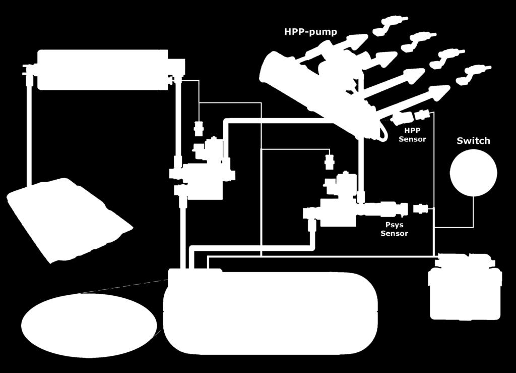
24 System Overview 24


25 Important when installing wiring Always disconnect the battery when installing / servicing the LPG system. Make sure the ignition key is out side the car. Be aware of central door locking, radio / telephone memory code and alarm system. Do not place the main fuse into the fuse holder before having completed the installation of the system. Solder and insulate all electrical connections. Make professional joints using solder and shrink tubing. The wires in the loom are provided with numbers and text. The text on the wire explains the function of the wire. The wire harness is not model specific, therefore is it may be necessary to adjust the length of the wires. Ensure maximum care is taken when connecting wiring. Do not stretch the wiring harness. Never disconnect the AFC connector, unless you have removed the main fuse. Correctly crimping and insulating a cable eye terminal: wire stripper crimping tool hot air gun Application: - Use this application for battery+ and ground connections. - Put the adhesive lined heat shrink tubing over the spot that needs the water tight insulation. - Use a heat gun to shrink the tubing. - Heat the tubing until glue comes out of both ends. - Let the tubing cool down until the glue is solidified. - (information bulletin 254) 25

26 Wiring DLM 26
27 Wiring DLM-2.0 / AFC
28 Flow Chart : System Status : Petrol Gas Fuel Pressure greater than 3 bar? Supply Problem! Lock off valve on Boost Pump open? Gas Fuel Pressure greater than 10 bar? Check power supply and ground of the lock off valve ( supply ). No load or Short error on the petrol supply lock off valve : Replace the Boost Pump. Are the banjo filters extremely polluted? No fault in the Low pressure section! FSU or FRU internal leakage. Replace FSU & FRU. ( call Prins! ) Is there pressure on the gas inlet of the FSU? Replace banjo filters. Replace FSU! Is the pressure at the inlet of the Boost Pump? Replace Boost Pump! Supply Problem! Check petrol pump, petrol error codes, fuses, etc. 28
29 Flow Chart : System Status : Petrol Gas Delay / Petrol Flush / Petrol Gas Boost / Petrol after Flush Gas Fuel Pressure greater than 16 bar? Supply Problem! Lock off valve on Boost Pump open? No fault in the Low Pressure section! Check power supply and ground of the lock off valve ( supply ). No load or Short error on the petrol supply lock off valve : Replace the Boost Pump. Is the Boost Pump active? ( 12V supply on the Boost Pump ) Check the fuse of the Boost Pump! Fuse OK? Replace Boost Pump! Check Boost Pump relay, wiring and control! Replace the fuse! 29
30 Flow Chart : System Status : GAS Fuel System Pressure greater than 11 bar? Supply Problem! Return Problem! Pump Driver Power > 25 Watt? System Pressure drop more then 1 bar during switch over from GAS Return Closed > GAS hot. Pump Driver OK? ( Pump Driver diagnose chart ) Check the tank lock off valve. ( does it open audible? ) Call your importer! Blockage in return? Are multi-restiction valve and banjo filter polluted? Replace the Pump Driver! Check wiring / replace valve. Replace FSU! Replace the entire Fuel Module! Replace banjo filter, clean restriction in fuel Module. Replace FRU! 30
31 Flow Chart : System Status : Gas Hot Fuel Fuel System Pressure greater than 14 bar? Supply Problem! Pump Driver Power > 100 Watt? System Pressure increases more then 2 bar while disconnecting FRU lock off valve? Pump Driver OK? ( Pump Driver diagnose chart ) Check the tank lock off valve. ( does it open audible? ) Call your importer! Blockage in return? Are multi-restiction valve and banjo filter polluted? Replace the Pump Driver! Check wiring / replace valve. Replace FSU! Replace the entire Fuel Module! Replace banjo filter, clean restriction in Fuel Module. Replace FRU! 31
32 Flow Chart : System Status : Gas Supply Control / Gas Return Closed Fuel System Pressure greater than 13.5 bar? Supply Problem! Pump Driver Power > 100 Watt? Call your importer! Pump Driver OK? Pump Driver OK? ( Pump Driver diagnose chart ) Check the tank lock off valve. ( does it open audible? ) Replace the Pump Driver! Check wiring / replace valve. Replace FSU! Replace the entire Fuel Module! 32
33 Flow Chart : Pump Driver Diagnose Pump Driver power circuit PROBLEM! Is the tank valve controlled? ( audible opened during SSH GAS status ) Check by measuring valve supply => ( Battery voltage-2volt ) Pump Driver power circuit OK! Check supply Pump Driver circuit with wiring diagram. Pump Driver feedback signal too Low 130 error code active? Pump Driver feedback signal too High 131 error code active? Check pump driver feedback signal wire ( wire 64. ) for open circuit or short to ground. DLM system shows a tank-empty message on hydraulic gas system status within 10 sec. Check pump driver feedback signal wire ( wire 64. ) for short to supply. Check control circuits to the fuel pump. OK? Info: Resistance fuel < 2 Ohm Replace the entire Fuel Module! 33

34 Direct LiquiMax Gen3 New improved component design: - Fuel Management Unit (Fuel Supply Unit + Fuel Return Unit) - Boost pump - Fuel module - Improved vehicle range ( +10%) - Fuel module with Jet-pump principle - More stable tank-empty behaviour - Improved system diagnosis - Auto diagnose function - Improved calibration stability - New software model for low pressure and high pressure control - Less sensitive to fuel quality and fuel composition variation (Propane / Butane) - Improved filter plan - P/T sensor implemented in Fuel module 34
 Boost pump 2 High pressure components High pressure")
 Pump driver Fuel selector switch Wiring harness Pressure sensor Direct LiquiMax Gen3")
35 1 Low pressure components Tank + Frame + Filler Fuel module (Multi-valve, fittings, fuel pump) Fuel lines: low pressure lines + fittings Fuel Management Unit (FMU) Boost pump 2 High pressure components High pressure pump (OEM) High pressure lines + fittings (OEM) Injector rail (OEM) 3 Electrical components Alternative Fuel Controller (AFC) Pump driver Fuel selector switch Wiring harness Pressure sensor Direct LiquiMax Gen3 components 35

![During the switchover from LPG to petrol, the LPG [remaining] in the fuel](/docs-images/90/103034789/images/36-6.jpg "supply line between the Fuel Management Unit and high pressure pump has to")


36 Boost Pump type 5 The boost pump is installed in line with the petrol supply line. During the switchover from LPG to petrol, the LPG [remaining] in the fuel supply line between the Fuel Management Unit and high pressure pump has to be purged back to the LPG tank. As the LPG supply line pressure is higher than the petrol supply line pressure a boost pump is needed. While switching from LPG to petrol the boost pump will increase the petrol supply line pressure so that the LPG in the fuel supply line will be purged through the return and is fed back to the LPG tank. Increase the gasoline supply pressure New compact light weight design Increased boost pressure Easy mounting system Improved electrical connections Integrated inlet filtering (Banjo-bolt filters no longer necessary) Not compatible with 1st generation type 1 & 2 boost pump! Compatible with 2nd generation type 3 & 4 boost pump! 36


 Integrated")
37 Fuel Management Unit The Fuel Management Unit (FMU) is designed to allow switching between petrol and gas. By controlling the supply lock off valve on the Management Unit the LPG supply to the high pressure pump can be controlled. During LPG mode the return lock off valve on the Management Unit opens the return line to the LPG tank. The return line makes it possible to feed the liquid LPG back to the LPG tank. During petrol operation the fuel return line to the LPG tank will be closed by the lock off valve on the Management Unit. The Fuel Supply and the Fuel Return are both controlled by the AFC. New compact design Combination of FSU + FRU Integrated LPG supply filter (service filter) Integrated permanent inlet filters (Banjo-bolt filters no longer necessary) Integrated Pressure/Temperature sensor 37
 Non Return Valve ( NRV ) Excess")
![flow valve Long life filter inside swirl pot [10 micron] 1. Fuel Module 2. Level indicator 3. Lock-off valve 4. Pressure relief valve 5. Power supply pump 6.](/docs-images/90/103034789/images/38-2.jpg "Fuel return connection 7. Pressure/Temperature sensor 8. Filler hose connection 9. Fuel supply connection 10. LPG pump inside 11. 80% / Level floater 12.")
38 Fuel Module type 3 Function: Provide housing for all fittings Mounting facility for turbine pump Swirl pot prevents vapour suction during dynamic driving Gas tight sealing between tank and fuel module by o-ring Fuel metering 80% fill stop Electric Lock off valve Pressure Relief Valve ( PRV ) Non Return Valve ( NRV ) Excess flow valve Long life filter inside swirl pot [10 micron] 1. Fuel Module 2. Level indicator 3. Lock-off valve 4. Pressure relief valve 5. Power supply pump 6. Fuel return connection 7. Pressure/Temperature sensor 8. Filler hose connection 9. Fuel supply connection 10. LPG pump inside % / Level floater 12. Swirl pot 13. Filter 38

39 DLM-Gen3 Electrical Diagram 39
40 DLM-Gen3 Connector pinout 40
ENGINE DISPLACEMENT 2000 NUMBER OF VALVES 16 ENGINE SET NUMBER
 MANUFACTURER Subaru TYPE Forester ENGINE DISPLACEMENT 2000 NUMBER OF VALVES 16 ENGINE CODE / NUMBER FA20 DIT VEHICLE CATEGORIES M TRANSMISSION AT VERSION Direct LiquiMax-2.1 PETROL ECU MANUFACTURER / CODE
ENGINE DISPLACEMENT NUMBER OF VALVES 16 VEHICLE CATEGORIES
 MANUFACTURER Dacia TYPE Duster ENGINE DISPLACEMENT 1200cc NUMBER OF VALVES 16 ENGINE CODE / NUMBER H5F (TCe125) VEHICLE CATEGORIES M TRANSMISSION MT (6-speed) VERSION AFC-2.1 PETROL ECU MANUFACTURER /
ENGINE DISPLACEMENT NUMBER OF VALVES ENGINE SET NUMBER VEHICLE CATEGORIES. Direct LiquiMax-2.0 PETROL ECU MANUFACTURER / CODE Bosch MED 17.
 MANUFACTURER VOLVO TYPE V60 / V70 T4F ENGINE DISPLACEMENT 1600cc NUMBER OF VALVES 16v ENGINE CODE / NUMBER B4164T2 VEHICLE CATEGORIES M TRANSMISSION MT/AT VERSION Direct LiquiMax-2.0 PETROL ECU MANUFACTURER
Megane Estate ENGINE DISPLACEMENT NUMBER OF VALVES VEHICLE CATEGORIES
 MANUFACTURER Renault TYPE Megane Estate ENGINE DISPLACEMENT 1200cc NUMBER OF VALVES 16v ENGINE CODE / NUMBER H5F (TCe115) VEHICLE CATEGORIES M TRANSMISSION MT(6) VERSION AFC-2.1 PETROL ECU MANUFACTURER
MANUFACTURER Explorer Sport ENGINE DISPLACEMENT NUMBER OF VALVES FIRING ORDER VEHICLE CATEGORIES TRANSMISSION
 MANUFACTURER Ford TYPE Explorer Sport ENGINE DISPLACEMENT 3500cc NUMBER OF VALVES 24v ENGINE CODE / NUMBER 3.5L GTDi Ecoboost FIRING ORDER 1 4 2 5-3 - 6 VEHICLE CATEGORIES M TRANSMISSION AT VERSION AFC-2.1
MANUFACTURER TYPE F-150 ENGINE DISPLACEMENT NUMBER OF VALVES FIRING ORDER VEHICLE CATEGORIES TRANSMISSION
 MANUFACTURER Ford TYPE F-150 ENGINE DISPLACEMENT 3500cc NUMBER OF VALVES 24v ENGINE CODE / NUMBER - OUTPUT 3.5L EcoBoost 2015 365hp FIRING ORDER 1-4-2-5-3-6 VEHICLE CATEGORIES M TRANSMISSION AT VERSION
MAKE OF AUTOMOBILE: TYPE: 508 PISTON DISPLACEMENT: NUMBER OF VALVES: FIRING ORDER: TRANSMISSION TYPE ( MT / AT ) VEHICLE CATEGORIES M or N
 VEHICLE CATEGORIES M or N") MAKE OF AUTOMOBILE: Peugeot TYPE: 508 PISTON DISPLACEMENT: 1600cc NUMBER OF VALVES: 16v ENGINE NUMBER: EP6CDT 115kW FIRING ORDER: 1-3-4-2 TRANSMISSION TYPE ( MT / AT ) MT VEHICLE CATEGORIES M or N M TYPE
MAKE OF AUTOMOBILE: Peugeot TYPE: 508 PISTON DISPLACEMENT: 1600cc NUMBER OF VALVES: 16v ENGINE NUMBER: EP6CDT 115kW FIRING ORDER: 1-3-4-2 TRANSMISSION TYPE ( MT / AT ) MT VEHICLE CATEGORIES M or N M TYPE
MODEL YEAR: 2010 SYSTEM APPROVAL NUMBER ( R115 ) R ENGINE SET NUMBER 349/ (.06 /.07 )
 R ENGINE SET NUMBER 349/ (.06 /.07 )") MAKE OF AUTOMOBILE: TYPE: IX35 PISTON DISPLACEMENT: 2000 NUMBER OF VALVES: 16 ENGINE NUMBER: G4KD TRANSMISSION TYPE ( MT / AT ) MT VEHICLE CATEGORIES M or N M TYPE VSI INJECTOR ( COLOUR ) Orange VERSION
MAKE OF AUTOMOBILE: TYPE: IX35 PISTON DISPLACEMENT: 2000 NUMBER OF VALVES: 16 ENGINE NUMBER: G4KD TRANSMISSION TYPE ( MT / AT ) MT VEHICLE CATEGORIES M or N M TYPE VSI INJECTOR ( COLOUR ) Orange VERSION
MAKE OF AUTOMOBILE: MODEL YEAR: 2004 SYSTEM APPROVAL NUMBER ( R115 ) ENGINE SET NUMBER 336/
 ENGINE SET NUMBER 336/") MAKE OF AUTOMOBILE: TYPE: A4 PISTON DISPLACEMENT: 1800 NUMBER OF VALVES: 20V ENGINE NUMBER: BFB TRANSMISSION TYPE ( MT / AT ) AT VEHICLE CATEGORIES M or N M TYPE VSI INJECTOR ( NUMBER + COLOR ) YELLOW
MAKE OF AUTOMOBILE: TYPE: A4 PISTON DISPLACEMENT: 1800 NUMBER OF VALVES: 20V ENGINE NUMBER: BFB TRANSMISSION TYPE ( MT / AT ) AT VEHICLE CATEGORIES M or N M TYPE VSI INJECTOR ( NUMBER + COLOR ) YELLOW
PISTON DISPLACEMENT: NUMBER OF VALVES: 16. TRANSMISSION TYPE ( MT / AT ) VEHICLE CATEGORIES M or N TYPE VSI INJECTOR ( COLOUR ) VERSION ( LPG / CNG )
 VEHICLE CATEGORIES M or N TYPE VSI INJECTOR ( COLOUR ) VERSION ( LPG / CNG )") MAKE OF AUTOMOBILE: TYPE: Ram PISTON DISPLACEMENT: 5700cc NUMBER OF VALVES: 16 ENGINE NUMBER: 5.7V8 Hemi 290kW TRANSMISSION TYPE ( MT / AT ) AT VEHICLE CATEGORIES M or N M TYPE VSI INJECTOR ( COLOUR )
MAKE OF AUTOMOBILE: TYPE: Ram PISTON DISPLACEMENT: 5700cc NUMBER OF VALVES: 16 ENGINE NUMBER: 5.7V8 Hemi 290kW TRANSMISSION TYPE ( MT / AT ) AT VEHICLE CATEGORIES M or N M TYPE VSI INJECTOR ( COLOUR )
MAKE OF AUTOMOBILE: MODEL YEAR: 2007 SYSTEM APPROVAL NUMBER ( R115 ) R ENGINE SET NUMBER 349/
 R ENGINE SET NUMBER 349/") MAKE OF AUTOMOBILE: KIA TYPE: CARENS PISTON DISPLACEMENT: 2000 NUMBER OF VALVES: 16 ENGINE NUMBER: G4KA TRANSMISSION TYPE ( MT / AT ) MT VEHICLE CATEGORIES M or N M TYPE VSI INJECTOR ( COLOUR ) ORANGE
MAKE OF AUTOMOBILE: KIA TYPE: CARENS PISTON DISPLACEMENT: 2000 NUMBER OF VALVES: 16 ENGINE NUMBER: G4KA TRANSMISSION TYPE ( MT / AT ) MT VEHICLE CATEGORIES M or N M TYPE VSI INJECTOR ( COLOUR ) ORANGE
MAKE OF AUTOMOBILE: ENGINE SET NUMBER 348/
 MAKE OF AUTOMOBILE: TYPE: CIVIC PISTON DISPLACEMENT: 1800 NUMBER OF VALVES: 16 ENGINE NUMBER: R18A TRANSMISSION TYPE ( MT / AT ) MT VEHICLE CATEGORIES M or N M TYPE VSI INJECTOR ( COLOR ) ORANGE VERSION
MAKE OF AUTOMOBILE: MODEL YEAR: 2007 SYSTEM APPROVAL NUMBER ( R115 ) VSI-LPG 10 ENGINE SET NUMBER 364/
 VSI-LPG 10 ENGINE SET NUMBER 364/") MAKE OF AUTOMOBILE: TYPE: FABIA PISTON DISPLACEMENT: 1400 NUMBER OF VALVES: 16 ENGINE NUMBER: BUD TRANSMISSION TYPE ( MT / AT ) MT VEHICLE CATEGORIES M or N M TYPE VSI INJECTOR ( NUMBER + COLOR ) 180/30410
MAKE OF AUTOMOBILE: TYPE: FABIA PISTON DISPLACEMENT: 1400 NUMBER OF VALVES: 16 ENGINE NUMBER: BUD TRANSMISSION TYPE ( MT / AT ) MT VEHICLE CATEGORIES M or N M TYPE VSI INJECTOR ( NUMBER + COLOR ) 180/30410
MAKE OF AUTOMOBILE: PISTON DISPLACEMENT: 1300
 MAKE OF AUTOMOBILE: TYPE: YARIS PISTON DISPLACEMENT: 1300 NUMBER OF VALVES: 16 VVT-I ENGINE NUMBER: 2SZ-FE TRANSMISSION TYPE ( MT / AT ) AT VEHICLE CATEGORIES M or N M TYPE VSI INJECTOR ( NUMBER + COLOR
PISTON DISPLACEMENT: 1200 NUMBER OF VALVES: ENGINE NUMBER: TRANSMISSION TYPE ( MT / AT ) VEHICLE CATEGORIES M or N TYPE VSI INJECTOR (COLOUR )
 VEHICLE CATEGORIES M or N TYPE VSI INJECTOR (COLOUR )") MAKE OF AUTOMOBILE: VOLKSWAGEN TYPE: POLO PISTON DISPLACEMENT: 1200 NUMBER OF VALVES: 8V ENGINE NUMBER: BZG TRANSMISSION TYPE ( MT / AT ) MT VEHICLE CATEGORIES M or N M TYPE VSI INJECTOR (COLOUR ) BLUE
MAKE OF AUTOMOBILE: VOLKSWAGEN TYPE: POLO PISTON DISPLACEMENT: 1200 NUMBER OF VALVES: 8V ENGINE NUMBER: BZG TRANSMISSION TYPE ( MT / AT ) MT VEHICLE CATEGORIES M or N M TYPE VSI INJECTOR (COLOUR ) BLUE
MAKE OF AUTOMOBILE: 316 / 318i E46 NUMBER OF VALVES:
 MAKE OF AUTOMOBILE: TYPE: 316 / 318i E46 PISTON DISPLACEMENT: 1800 2000 cc NUMBER OF VALVES: 16V ENGINE NUMBER: N42B18A / N42B20A TRANSMISSION TYPE ( MT / AT ) MT VEHICLE CATEGORIES M or N M TYPE VSI INJECTOR
MAKE OF AUTOMOBILE: ENGINE SET NUMBER 366/
 MAKE OF AUTOMOBILE: TYPE: SORENTO PISTON DISPLACEMENT: 3300 NUMBER OF VALVES: 24 ENGINE NUMBER: G6DB TRANSMISSION TYPE ( MT / AT ) MT VEHICLE CATEGORIES M or N M TYPE VSI INJECTOR ( NUMBER + COLOR ) 180/30340
MODEL YEAR: 2009 SYSTEM APPROVAL NUMBER ( R115 ) R ENGINE SET NUMBER 350/
 R ENGINE SET NUMBER 350/") MAKE OF AUTOMOBILE: TYPE: PRIORA 2170 / 2172 PISTON DISPLACEMENT: 1600 NUMBER OF VALVES: 16 ENGINE NUMBER: 21126 TRANSMISSION TYPE ( MT / AT ) MT VEHICLE CATEGORIES M or N M TYPE VSI INJECTOR (COLOR )
MAKE OF AUTOMOBILE: TYPE: PRIORA 2170 / 2172 PISTON DISPLACEMENT: 1600 NUMBER OF VALVES: 16 ENGINE NUMBER: 21126 TRANSMISSION TYPE ( MT / AT ) MT VEHICLE CATEGORIES M or N M TYPE VSI INJECTOR (COLOR )
MAKE OF AUTOMOBILE: TYPE: V 70 PISTON DISPLACEMENT: 2521 NUMBER OF VALVES:
 MAKE OF AUTOMOBILE: TYPE: V 70 PISTON DISPLACEMENT: 2521 NUMBER OF VALVES: 20V ENGINE NUMBER: B5254T TRANSMISSION TYPE ( MT / AT ) AT VEHICLE CATEGORIES M or N PASSENGER CAR ( M ) TYPE VSI INJECTOR (COLOUR
MODEL YEAR: SYSTEM APPROVAL NUMBER ( R115 ) R ENGINE SET NUMBER 354/
 R ENGINE SET NUMBER 354/") MAKE OF AUTOMOBILE: MERECEDES TYPE: E200 W211 PISTON DISPLACEMENT: 1796 NUMBER OF VALVES: 16 ENGINE NUMBER: M271 TRANSMISSION TYPE ( MT / AT ) AT VEHICLE CATEGORIES M or N M TYPE VSI INJECTOR ( NUMBER
MAKE OF AUTOMOBILE: MERECEDES TYPE: E200 W211 PISTON DISPLACEMENT: 1796 NUMBER OF VALVES: 16 ENGINE NUMBER: M271 TRANSMISSION TYPE ( MT / AT ) AT VEHICLE CATEGORIES M or N M TYPE VSI INJECTOR ( NUMBER
MODEL YEAR: 2007 SYSTEM APPROVAL NUMBER ( R115 ) R ENGINE SET NUMBER 350/
 R ENGINE SET NUMBER 350/") MAKE OF AUTOMOBILE: TYPE: KALINA 1117/ 1118 / 1119 PISTON DISPLACEMENT: 1600 NUMBER OF VALVES: 8 ENGINE NUMBER: 21114 TRANSMISSION TYPE ( MT / AT ) MT VEHICLE CATEGORIES M or N M TYPE VSI INJECTOR ( NUMBER
MAKE OF AUTOMOBILE: TYPE: KALINA 1117/ 1118 / 1119 PISTON DISPLACEMENT: 1600 NUMBER OF VALVES: 8 ENGINE NUMBER: 21114 TRANSMISSION TYPE ( MT / AT ) MT VEHICLE CATEGORIES M or N M TYPE VSI INJECTOR ( NUMBER
MAKE OF AUTOMOBILE: GRAND CHEROKEE PISTON DISPLACEMENT: 5700 NUMBER OF VALVES: 16
 MAKE OF AUTOMOBILE: TYPE: GRAND CHEROKEE PISTON DISPLACEMENT: 5700 NUMBER OF VALVES: 16 ENGINE NUMBER: 5.7V8 HEMI TRANSMISSION TYPE ( MT / AT ) AT VEHICLE CATEGORIES M or N M TYPE VSI INJECTOR ( NUMBER
MAKE OF AUTOMOBILE: PISTON DISPLACEMENT: 8300 NUMBER OF VALVES: 20 TRANSMISSION TYPE ( MT / AT ) TYPE VSI INJECTOR (COLOR ) VERSION ( LPG / CNG )
 TYPE VSI INJECTOR (COLOR ) VERSION ( LPG / CNG )") MAKE OF AUTOMOBILE: TYPE: PISTON DISPLACEMENT: 8300 NUMBER OF VALVES: 20 ENGINE NUMBER: SRT V10 Viper TRANSMISSION TYPE ( MT / AT ) AT TYPE VSI INJECTOR (COLOR ) YELLOW VERSION ( LPG / CNG ) LPG INJECTION
MAKE OF AUTOMOBILE: TYPE: PISTON DISPLACEMENT: 8300 NUMBER OF VALVES: 20 ENGINE NUMBER: SRT V10 Viper TRANSMISSION TYPE ( MT / AT ) AT TYPE VSI INJECTOR (COLOR ) YELLOW VERSION ( LPG / CNG ) LPG INJECTION
MAKE OF AUTOMOBILE: ENGINE SET NUMBER 337/
 MAKE OF AUTOMOBILE: TYPE: NITRO PISTON DISPLACEMENT: 3700 NUMBER OF VALVES: 12V ENGINE NUMBER: V6 TRANSMISSION TYPE ( MT / AT ) AT VEHICLE CATEGORIES M or N M TYPE VSI INJECTOR ( NUMBER + COLOR ) 180/30330
MAKE OF AUTOMOBILE: PISTON DISPLACEMENT: 2700 NUMBER OF VALVES:
 MAKE OF AUTOMOBILE: DODGE TYPE: JOURNEY PISTON DISPLACEMENT: 2700 NUMBER OF VALVES: 24V ENGINE NUMBER: 2.7V6 EER TRANSMISSION TYPE ( MT / AT ) AT VEHICLE CATEGORIES M or N M TYPE VSI INJECTOR ( COLOR )
MAKE OF AUTOMOBILE: NUMBER : 076/ DATE : Copyright Prins Autogassystemen B.V VERSION NR : B
 MAKE OF AUTOMOBILE: Ford TYPE: Mondeo PISTON DISPLACEMENT: 2000 NUMBER OF VALVES: 16 ENGINE NUMBER: AOBA TYPE VSI INJECTOR ( COLOR ) Yellow MODEL YEAR: 2010 ENGINE SET NUMBER 347/1810500.07 NUMBER : 076/0703201
Universal instructions CNG Tank-sets. MODEL year 2011 SET Number. NUMMER : DATE : Copyright Prins Autogassystemen B.V VERSIE NR : DB
 Universal instructions CNG Tank-sets Make universal MODEL year 2011 SET Number all NUMMER : DATE : 2011-09-12 TABLE OF CONTENTS... 1 Required equipment / tools / materials for installing a complete system...
Prins autogassystemen b.v. Veldhoven
 Prins autogassystemen b.v. Veldhoven MOUNTING INSTRUCTION ENGINE CONVERSION SET MAKE OF AUTOMOBILE: TYPE: ASTRA PISTON DISPLACEMENT: 2000 cc MT NUMBER OF VALVES: 16V ENGINE NUMBER: X20XEV INJECTION SYSTEM:
MAKE OF AUTOMOBILE: MODEL YEAR: SYSTEM APPROVAL NUMBER ( R115 ) E4-115R /-17 / DLM-LPG 01/10 MANUAL NUMBER: 076/ DATE
 E4-115R /-17 / DLM-LPG 01/10 MANUAL NUMBER: 076/ DATE") MAKE OF AUTOMOBILE: HYUNDAI TYPE: ix35 TANK CAPACITY: 74 Liter Fuel Module Stako toroidal TANK LOCATION SPARE WHEEL ROOM MODEL YEAR: 2010 SYSTEM APPROVAL NUMBER ( R115 ) E4-115R-0000-04/-17 / DLM-LPG 01/10
MAKE OF AUTOMOBILE: HYUNDAI TYPE: ix35 TANK CAPACITY: 74 Liter Fuel Module Stako toroidal TANK LOCATION SPARE WHEEL ROOM MODEL YEAR: 2010 SYSTEM APPROVAL NUMBER ( R115 ) E4-115R-0000-04/-17 / DLM-LPG 01/10
MAKE OF AUTOMOBILE: ENGINE SET NUMBER 345/ NUMBER : 076/ DATE : VERSION NR : B
 MAKE OF AUTOMOBILE: TYPE: LOGAN PISTON DISPLACEMENT: 1600 NUMBER OF VALVES: 8 ENGINE NUMBER: K7M 710 TRANSMISSION TYPE ( MT / AT ) MT VEHICLE CATEGORIES M or N ( M ) TYPE VSI INJECTOR ( NUMBER + COLOR
MAKE OF AUTOMOBILE: PISTON DISPLACEMENT: 1600 NUMBER OF VALVES: 16
 MAKE OF AUTOMOBILE: TYPE: MERIVA PISTON DISPLACEMENT: 1600 NUMBER OF VALVES: 16 ENGINE NUMBER: Z16XEP TRANSMISSION TYPE ( MT / AT ) MT VEHICLE TYPE M TYPE VSI INJECTOR ( NUMBER + COLOR ) 180/30430 ORANGE
MAKE OF AUTOMOBILE: MODEL YEAR: 2013 SYSTEM APPROVAL NUMBER ( R115 ) R MANUAL NUMBER: 076/ DATE
 R MANUAL NUMBER: 076/ DATE") MAKE OF AUTOMOBILE: Dacia TYPE: Lodgy TANK CAPACITY: 59 Liter Stako toroidal TANK LOCATION Spare Wheel Room / Underneath MODEL YEAR: 2013 SYSTEM APPROVAL NUMBER ( R115 ) R115-000013 BOOT SET NUMBER 345/070002/A
MAKE OF AUTOMOBILE: Dacia TYPE: Lodgy TANK CAPACITY: 59 Liter Stako toroidal TANK LOCATION Spare Wheel Room / Underneath MODEL YEAR: 2013 SYSTEM APPROVAL NUMBER ( R115 ) R115-000013 BOOT SET NUMBER 345/070002/A
MAKE OF AUTOMOBILE: PISTON DISPLACEMENT: NUMBER OF VALVES: ENGINE NUMBER: TRANSMISSION TYPE ( MT / AT ) VEHICLE CATEGORIES M or N PERSONEN AUTO ( M )
 VEHICLE CATEGORIES M or N PERSONEN AUTO ( M )") MAKE OF AUTOMOBILE: TYPE: WRANGLER PISTON DISPLACEMENT: 4000 cc NUMBER OF VALVES: 12 v ENGINE NUMBER: M3 TJ TRANSMISSION TYPE ( MT / AT ) MT VEHICLE CATEGORIES M or N PERSONEN AUTO ( M ) TYPE VSI INJECTOR
MAKE OF AUTOMOBILE: TYPE: WRANGLER PISTON DISPLACEMENT: 4000 cc NUMBER OF VALVES: 12 v ENGINE NUMBER: M3 TJ TRANSMISSION TYPE ( MT / AT ) MT VEHICLE CATEGORIES M or N PERSONEN AUTO ( M ) TYPE VSI INJECTOR
MAKE OF AUTOMOBILE: MODEL YEAR: 2010 SYSTEM APPROVAL NUMBER ( R115 ) BOOT SET NUMBER 947/
 BOOT SET NUMBER 947/") MAKE OF AUTOMOBILE: FORD TYPE: MONDEO TANK CAPACITY: 61 Liter WvM toroidal TANK LOCATION SPARE WHEEL ROOM MODEL YEAR: 2010 SYSTEM APPROVAL NUMBER ( R115 ) R115-0000** BOOT SET NUMBER 947/1810501 NUMBER:
MAKE OF AUTOMOBILE: FORD TYPE: MONDEO TANK CAPACITY: 61 Liter WvM toroidal TANK LOCATION SPARE WHEEL ROOM MODEL YEAR: 2010 SYSTEM APPROVAL NUMBER ( R115 ) R115-0000** BOOT SET NUMBER 947/1810501 NUMBER:
DieselBlend LPG. a Westport Fuel Systems company
 a Westport Fuel Systems company DieselBlend LPG Prins Autogassystemen B.V., specialized in alternative fuel systems, developed a new dual-fuel system for heavy-duty applications: Prins Dieselblend LPG
Installation Instructions General Motors 8.1 Sequential Vapor Injection (S.V.I.) System 7500/6500 Series Trucks model year.
 System 7500/6500 Series Trucks model year.") Installation Instructions General Motors 8.1 Sequential Vapor Injection (S.V.I.) System 7500/6500 Series Trucks 2003-2005 model year. Technocarb Equipment (2004) Ltd. 4-30435 Progressive Way Abbotsford,
Installation Instructions General Motors 8.1 Sequential Vapor Injection (S.V.I.) System 7500/6500 Series Trucks 2003-2005 model year. Technocarb Equipment (2004) Ltd. 4-30435 Progressive Way Abbotsford,
DATE : VERSION NR :
 DATE : 07032006 VERSION NR : B Table of contents General instructions 2 Introduction 3 Overview VSI system 4 Approval numbers VSI components 4 The ucer 5 The injector rail 6 The filter unit 7 The VSI computer
1998 ENGINE PERFORMANCE. General Motors Corp. - Basic Diagnostic Procedures - 5.7L
 INTRODUCTION 1998 ENGINE PERFORMANCE General Motors Corp. - Basic Diagnostic Procedures - 5.7L The following diagnostic steps will help prevent overlooking a simple problem. This is also where to begin
WORLD LEADER IN ALTERNATIVE FUEL SYSTEMS CALIBRATION PARAMETERS
 WORLD LEADER IN ALTERNATIVE FUEL SYSTEMS CALIBRATION PARAMETERS VSI-2.0 LPG UNIVERSAL KIT Version: Back V2.4 to Parameter 03-2018 Overview Page 1 of 53 Copyright Prins Autogassystemen B.V. 2018 Back to
NCT-1000 Users Manual
 NCT-000 Users Manual NCT 000 KIT 3 6 5 9 0 7 8 0 5 6 7 8 9 3 NCT-000 KIT. TOOL CASE. RAIL PLUG (mm) 5ea ( for spare) 3. RAIL PLUG (mm) 5ea ( for spare). FLASK & HOLDER ea 5. VISIBLE TUBE ea 6. INJECTOR
3.4L V6 SUPERCHARGER 7 TH INJECTOR KIT
 Part Number: 00602-17620-260 00602-17620-261 00602-17620-263 00602-17620-264 00602-17620-274 00602-17620-275 00602-17620-276 Section I Installation Preparation Kit Contents Item # Quantity Reqd. Description
Document ID# Chevrolet Corvette
 Page 1 of 6 Document ID# 610892 2000 Chevrolet Corvette Feedback Print D T C P 0 4 6 2 F u e l L e v e l S e n s o r C i r c u i t L o w V o l t a g e C i r c u i t D e s c r i p t i
Instruction of connection and programming of the VECTOR controller
 Instruction of connection and programming of the VECTOR controller 1. Connection of wiring 1.1.VECTOR Connection diagram Fig. 1 VECTOR Diagram of connection to the vehicle wiring. 1.2.Connection of wiring
Wiring for OMS/Mid-engine layout
 Wiring for OMS/Mid-engine layout Coil connectors Crank sensor Coolant temperature sensor Cam sensor Connector for fuel pump Connector for joining new wiring harness to existing Suzuki wiring will need
Operating and Installation Instructions
 Model Number 40401-c (-sp) Electronic Fuel Pump Operating and Installation Instructions This Product is Patent Pending. Application available upon request CAUTION! This product is to be installed only
DTC P1431 Fuel Level Sensor 2 Performance
 Page 1 of 8 Document ID# 610929 2000 Chevrolet Corvette Feedback Print DTC P1431 Fuel Level Sensor 2 Performance Circuit Description The right fuel level sensor 2, mounted in the rear
SYSTEM OPERATION IMPORTANT CAUTIONS
 SYSTEM OPERATION The system is turned on by placing the gear shift lever in the reverse position. The green light on the cab Control Box will illuminate to indicate the system is operating. When an object
Installation and Operation Guide. Tundra HD 2500 Power Inverter. for the. Webasto BlueCool Truck System
 Installation and Operation Guide Tundra HD 2500 Power Inverter for the Webasto BlueCool Truck System www.tundrainternational.com www.techwebasto.com BCTSP0063A Table of Contents 1. Introduction 4 1.1 Disclaimer.................................................................................
LAMBDA SENSOR CONTROLLER
 LAMBDA SENSOR CONTROLLER INSTALLATION & PROGRAMMING MANUAL version : V1.77 -V1.79 Manufacturer: AC Spółka Akcyjna. 15-182 Białystok, ul. 27 Lipca 64, Poland tel. +48 85 7438148, fax +48 85 653 8649 www.ac.com.pl,
DTC P0341 Camshaft Position (CMP) Sensor Performance
 Sensor Performance") Page 1 of 5 1999 Buick Century Century, Regal VIN W Service Manual Document ID: 345654 DTC P0341 Camshaft Position (CMP) Sensor Performance Circuit Description During cranking, the Ignition Control Module
Page 1 of 5 1999 Buick Century Century, Regal VIN W Service Manual Document ID: 345654 DTC P0341 Camshaft Position (CMP) Sensor Performance Circuit Description During cranking, the Ignition Control Module
LCD EWP /FAN DIGITAL CONTROLLER Installation Instructions
 77 Taras Avenue P.O. Box 363 Altona North Vic 3025 Australia Phone: +61(0)3 9369 1234 Fax: +61(0)3 9369 3456 Email: info@daviescraig.com.au Web: www.daviescraig.com.au LCD EWP /FAN DIGITAL CONTROLLER Installation
Error codes Diagnostic plug Read-out Reset Signal Error codes
 Error codes Diagnostic plug Diagnostic plug: 1 = Datalink LED tester (FEN) 3 = activation error codes (TEN) 4 = positive battery terminal (+B) 5 = ground Read-out -Connect LED tester to positive battery
Nero 6600H/6601H. Installation Guide. Commercial Vehicle Productivity and Security. Antenna Configuration
 Commercial Vehicle Productivity and Security The 6600H/6601H is a versatile and economical GPS tracking beacon designed for fleet management needs in all commercial vehicles. The H designation in the model
CAUTION: CAREFULLY READ INSTRUCTIONS BEFORE PROCEEDING. NOT LEGAL FOR USE OR SALE ON POLLUTION CONTROLLED VEHICLES.
 Twin Tec Installation Instructions for VRFI D Version Fuel Injection Controller CAUTION: CAREFULLY READ INSTRUCTIONS BEFORE PROCEEDING. T LEGAL FOR USE OR SALE ON POLLUTION CONTROLLED VEHICLES. OVERVIEW
HIGH FUEL PRESSURE LINE
 16 07 HIGH FUEL PRESSURE LINE High Pressure Pump Description This pump generates high fuel pressure and is driven by timing chain (radial plunger principle). This pump pressurizes the fuel to approx. 1600
Powertrain DTC Summaries EOBD
 Powertrain DTC Summaries Quick Reference Diagnostic Guide Jaguar X-TYPE 2.0 L 2002.25 Model Year Refer to page 2 for important information regarding the use of Powertrain DTC Summaries. Jaguar X-TYPE 2.0
VERSUS GAS USA 1/1/2013
 GRATEC: ALTERNATIVE FUELS DIVISION USER S MANUAL VERSUS GAS Premium Sequential Systems VERSUS GAS USA 1/1/2013 This manual describes all possible scenarios the user may face as well as the safe operation
Operating Manual OBD Link Connector
 Operating Manual OBD Link Connector OBD Link Connector (OLC) provides the following functions when it is plugged into the car or truck Diagnostic Link Connector (DLC) port: 1. TEST OBD2 PORT BEFORE PLUG
Malfunction Criteria and Threshold Value Adaptive value. Secondary Parameters with Enable Conditions. >50.8 S Engine load 9-45% Delta fuel adaptation
 DTC Error Message P0171 System Too Lean (Bank 1) Diagnostic Procedure Check fuel pump delivery and quantity. Refer to page 126. Check Fuel pressure regulator and residual pressure. Refer to Fuel Injection
General Service Information
 KYMCO MXU 500i/700i Repair Manual Fuel System MXU 700i 3.Fuel System MXU 700i This chapter covers the location and servicing of the fuel system components for the fuel injected KYMCO MXU 700i models. 1.Airbox...
2002 ENGINE PERFORMANCE. Self-Diagnostics - RAV4. Before performing testing procedures, check for any related Technical Service Bulletins (TSBs).
.") 2002 ENGINE PERFORMANCE Self-Diagnostics - RAV4 INTRODUCTION NOTE: Before performing testing procedures, check for any related Technical Service Bulletins (TSBs). To properly diagnosis and repair this
2002 ENGINE PERFORMANCE Self-Diagnostics - RAV4 INTRODUCTION NOTE: Before performing testing procedures, check for any related Technical Service Bulletins (TSBs). To properly diagnosis and repair this
IVTM Installation Manual
 Integrated Vehicle Tire Pressure Monitoring IVTM Installation Manual 2nd edition Copyright WABCO 2006 Vehicle Control Systems An American Standard Company The right of amendment is reserved Version 002/06.06(us)
M-9603-SVT mm Cold Air Kit w/premium Calibration INSTALLATION INSTRUCTIONS
 Please contact the Tech Line for the most current instruction information (800) 367-3788.!!! PLEASE READ THE FOLLOWING INSTRUCTIONS CAREFULLY PRIOR TO INSTALLATION!!! OVERVIEW: This kit is designed for
Overview of operation modes
 Overview of operation modes There are three main operation modes available. Any of the modes can be selected at any time. The three main modes are: manual, automatic and mappable modes 1 to 4. The MapDCCD
Parts and Accessories Installation Instructions
 Parts and Accessories Installation Instructions F 53 7 W Retrofit auxiliary heating system BMW X5 (E 53) with M57 engine (diesel) The installation time is approx..5-4.5 hours (see important information),
BASIC DIAGNOSTIC PROCEDURES
 BASIC DIAGNOSTIC PROCEDURES 2001 Chevrolet Camaro 2001 ENGINE PERFORMANCE Basic Diagnostic Procedures - Cars Except Metro & Prizm MODEL IDENTIFICATION MODEL IDENTIFICATION Body Code (1) Model C... Park
Current Content Edition 55
 Current Content Edition 55 Fundamentals Electrics Essential Electrical Skills Introduction to Electrics 166909 Fundamentals Electrics Essential Electrical Skills Voltage, Current and Resistance 147570
On Board Diagnostics II PCED
 Page 1 of 5 1999 PCED On Board Diagnostics II SECTION 5: Pinpoint Tests HD: Misfire Detection Monitor HD: Introduction HD1 DTC P0301-P0310: CHECK FOR NO LOW FUEL te: Running out of fuel can turn on the
REC-11+ REMOTE RECEIVER UNIT
 Resetting The Programmable Features The installer may quickly and easily return all 17 programmable features back to the factory settings. Changing individual features were explained in detail in the previous
Using the Gratec Gasoline software
 Using the Gratec Gasoline software The Gratec Software is a sophisticated yet user friendly program in which configures the Gratec CNG or LPG system to perform with your vehicle. Software version 2.002
CARM INTERNATIONAL TOWING MODULES
 CARM INTERNATIONAL TOWING MODULES (TA100/200 Instructions Revision = 1) Each Towing Module (if ordered with Loom Pack) is shipped with: A/ These instructions B/ 1 x Towing Control Module C/ 1 x high current
Electronic Ballast EVG 2000-T
 Electronic Ballast EVG 2000-T Operating Manual Table of contents 1 Description 1.1 Advantages of this ballast... 3 1.2 Functional principle... 3 1.3 Energization... 4 1.4 Visualization... 5 1.5 Indications
EG DYNAMIC user manual
 Timing Advance Processor EG DYNAMIC user manual ver. 1.1.0 dated 2012-10-01 This instruction can be also downloaded from: http://www.europegas.pl/en/technical-support/service-manuals Latest software version
ENGINE COOLING GROUP CONTENTS GENERAL INFORMATION SERVICE SPECIFICATIONS COOLANT SEALANT THERMOSTAT...
 14-1 GROUP 14 CONTENTS GENERAL INFORMATION 14-2 SERVICE SPECIFICATIONS 14-2 COOLANT 14-3 SEALANT 14-3 DIAGNOSIS 14-3 INTRODUCTION 14-3 TROUBLESHOOTING STRATEGY 14-3 SYMPTOM CHART 14-3 SYMPTOM PROCEDURES
1993 ENGINE PERFORMANCE Volkswagen Basic Diagnostic Procedures. Cabriolet, Corrado SLC, EuroVan, Fox, Golf, GTI, Jetta, Passat GL, Passat GLX
 Article Text ARTICLE BEGINNING 1993 ENGINE PERFORMANCE Volkswagen Basic Diagnostic Procedures Cabriolet, Corrado SLC, EuroVan, Fox, Golf, GTI, Jetta, Passat GL, Passat GLX INTRODUCTION The following diagnostic
Fuel Management...26 Principle of Operation...32 Workshop Hints...38 Tools and Equipment...42
 Table of Contents MS45 - E85 with M54 Engine Subject Page MS45........................................................2 Objectives of the Module.......................................2 Purpose of the System.........................................3
Manifold QF. Contents. Description. Installation & Setup Guide. Safety 3. Introduction 3. Installation Standards 4. Specifications 5.
 Contents Description Page Safety 3 Introduction 3 Installation Standards 4 Specifications 5 Materials 5 Overall System Configurations 6 Manifold Installation 7 Fixing Unit to Wall 7 Water Connection 8
EVAP system, servicing
 Page 1 of 65 20-130 EVAP system, servicing EVAP system components 1 - Cap nut 10 Nm 2 - Cover 3 - Stud For EVAP canister 15 Nm 4 - Sealing piece 5 - Bleed line To EVAP canister purge regulator valve -
KIA CRT Common Rail Injector Tester User s Manual. Delphi A2 U2 Engine. PIEZO, S & R Engine
 KIA CRT-3500 Common Rail Injector Tester User s Manual PIEZO, S & R Engine Delphi A U Engine Contents. PRODUCT COMPOSITION. INJECTION TEST -. Injection Comparison Test ( Low Pressure Mode ) -. Injection
G - TESTS W/CODES - 2.2L
 G - TESTS W/CODES - 2.2L 1994 Toyota Celica 1994 ENGINE PERFORMANCE Toyota 2.2L Self-Diagnostics Celica INTRODUCTION If no faults were found while performing F - BASIC TESTING, proceed with self-diagnostics.
512 HO M285 Engine (FrechW) Maybach Engine M285
 Maybach Engine M285") 512 HO M285 Engine (FrechW) 08-06-03 Maybach Engine M285 These technical training materials are current as of the date noted on the materials, and may be revised or updated without notice. Always check
512 HO M285 Engine (FrechW) 08-06-03 Maybach Engine M285 These technical training materials are current as of the date noted on the materials, and may be revised or updated without notice. Always check
USER INSTRUCTIONS STRIKER LED USER INSTRUCTIONS
 USER INSTRUCTIONS STRIKER LED USER INSTRUCTIONS 1 DIY TWIN PACK WITH INSTALLATION KIT CONTENTS 2 x Striker LED driving lights 2 x Spot filters 2 x Reversible mount and hardware 1 x User instructions 1
Congratulations on purchasing the Edge Juice/Attitude system for the Dodge Cummins Diesel.
 Getting Started About the Juice Congratulations on purchasing the Edge Juice/Attitude system for the Dodge Cummins Diesel. The Juice/Attitude system features an intelligent module (Juice) that acts as
Fitting Instructions: Street Triple from VIN and Street Triple R from VIN A
 English Fitting Instructions: Street Triple from VIN 560477 and Street Triple R from VIN 560477 A9808113 Thank you for choosing this Triumph genuine accessory kit. This accessory kit is the product of
WirelessAIR Advanced Integrated Remote
 Advanced Integrated Remote Gen 3 Kit 72000 Automatic Leveling Digital On-Board Compressor System MN-772 (021112) ECR 7233 INSTALLATION GUIDE For maximum effectiveness and safety, please read these instructions
REMOVAL AND INSTALLATION
 501-20B-1 REMOVAL AND INSTALLATION 501-20B-1 Occupant Classification Sensor Item Part Number Description 7 61704 Seat track assembly Special Tool(s) 8 Safety belt buckle switch electrical connector (part
AviStart 3000 Installation Manual
 Table of Contents Important Information... 2 Recommended Installation Tools... 2 Recommended Procedures... 2 Main Wiring Diagram... 3 12 Pin Connector... 4 6 Pin Connector... 4 Installation Procedures...5
ARTICLE BEGINNING INTRODUCTION SELF-DIAGNOSTIC SYSTEM RETRIEVING DTCS ENGINE PERFORMANCE Volkswagen Self-Diagnostics - Gasoline
 Article Text ARTICLE BEGINNING 1996 ENGINE PERFORMANCE Volkswagen Self-Diagnostics - Gasoline Cabrio, Golf III, GTI, Jetta III, Passat INTRODUCTION If no faults were found while performing preliminary
ALTERNATOR REQUESTED INFORMATION. Vehicles With Dual Generator [ Engine Mount - LH ] 2007 Ford Pickup 6.0L Eng F350 Super Duty
![ALTERNATOR REQUESTED INFORMATION. Vehicles With Dual Generator [ Engine Mount - LH ] 2007 Ford Pickup 6.0L Eng F350 Super Duty](/thumbs/72/66590437.jpg "ALTERNATOR REQUESTED INFORMATION. Vehicles With Dual Generator [ Engine Mount - LH ] 2007 Ford Pickup 6.0L Eng F350 Super Duty") ALTERNATOR 2007 Ford Pickup 6.0L Eng F350 Super Duty REQUESTED INFORMATION Vehicles With Dual Generator [ Engine Mount - LH ] Fig 1: Rotating Drive Belt Tensioner Clockwise 1. Remove the accessory drive
ALTERNATOR 2007 Ford Pickup 6.0L Eng F350 Super Duty REQUESTED INFORMATION Vehicles With Dual Generator [ Engine Mount - LH ] Fig 1: Rotating Drive Belt Tensioner Clockwise 1. Remove the accessory drive
F - BASIC TESTING Toyota Celica INTRODUCTION PRELIMINARY INSPECTION & ADJUSTMENTS VISUAL INSPECTION MECHANICAL INSPECTION
 F - BASIC TESTING 1994 Toyota Celica 1994 ENGINE PERFORMANCE Toyota 4-Cylinder Basic Diagnostic Procedures Celica INTRODUCTION The following diagnostic steps will help prevent overlooking a simple problem.
TurfDefender Electronic Leak Detector Kit Reelmaster 5000, 6000 and 5010 Series Traction Units
 Form No. 56 586 Rev A TurfDefender Electronic Leak Detector Kit Reelmaster 5000, 6000 and 500 Series Traction Units Model No. 05 Installation Instructions The Installation Instructions for Reelmaster 5000/6000
These instructions were written for reference only and the use of a factory service manual is recommended.
 Introducing the CorkSport High Pressure Fuel Line designed for the MZR DISI. This fuel line is designed to replace the OEM fuel line which are prone to failure at the brazed connection at the rail. The
MFI Pro - Instructional Manual (Toyota 1uzfe) Version 06.01
 Version 06.01") Tel: 011 3971953 - Fax: 011 3978197 - info@gotech.co.za www.got e ch.c o.za MFI Pro - Instructional Manual (Toyota 1uzfe) Version 06.01 Index: Introduction 1 Before You Begin 1 Basic Tools Required 2 Basic
Tel: 011 3971953 - Fax: 011 3978197 - info@gotech.co.za www.got e ch.c o.za MFI Pro - Instructional Manual (Toyota 1uzfe) Version 06.01 Index: Introduction 1 Before You Begin 1 Basic Tools Required 2 Basic
2012 Chevy Truck Equinox FWD L4-2.4L Vehicle > Locations > Components
 2012 Chevy Truck Equinox FWD L4-2.4L Vehicle > Locations > Components 2012 Chevy Truck Equinox FWD L4-2.4L Vehicle > Powertrain Management > Fuel Delivery and Air Induction > Description and Operation
NATEF ENGINE PERFORMANCE CHECKLIST Name Date Period
 NATEF ENGINE PERFORMANCE CHECKLIST Name Period For every task in Engine Performance the following safety requirement must be strictly enforced: Comply with personal and environmental safety practices associated
Powertrain DTC Summaries OBD II
 Powertrain DTC Summaries Quick Reference Diagnostic Guide Jaguar X-TYPE 2.5L and 3.0L 2002 Model Year Revised January, 2002: P0706, P0731, P0732, P0733, P0734, P0735, P0740, P1780 POSSIBLE CAUSES Revised
HYUNDAI CIT Common Rail Injector Tester User s Manual. A, U, D, J, S, R Engine & U-II, A-II Digital Controller
 HYUNDAI CIT-3500 Common Rail Injector Tester User s Manual A, U, D, J, S, R Engine & U-II, A-II Digital Controller Contents. PRODUCT COMPOSITION. INJECTION TEST ) Injection Comparison Test ( Low Pressure
These instructions were written for reference only and the use of a factory service manual is recommended.
 Introducing the CorkSport High Pressure Fuel Line designed for the MZR DISI. This fuel line is designed to replace the OEM fuel line which are prone to failure at the brazed connection at the rail. The
Technical Installation Guide
 Technical Installation Guide ID Technical Document: DT_IS_GAI-005 Rev. Date Review n. Issued by Reviewed/ Approved 0 13/04/2007 First Issue Technical office ROS 1 19/02/2009 Second Issue Technical office
Installation Instructions for the Lingenfelter Gen 6 Camaro Boost-A-Pump (BAP) Kit
 Kit") Installation Instructions for the Lingenfelter Gen 6 Camaro Boost-A-Pump (BAP) Kit PN: L460417316 Lingenfelter Performance Engineering 1557 Winchester Road Decatur, IN 46733 (260) 724-2552 (260) 724-0422
Installation Instructions for the Lingenfelter Gen 6 Camaro Boost-A-Pump (BAP) Kit PN: L460417316 Lingenfelter Performance Engineering 1557 Winchester Road Decatur, IN 46733 (260) 724-2552 (260) 724-0422