PISTON DISPLACEMENT: NUMBER OF VALVES: 16. TRANSMISSION TYPE ( MT / AT ) VEHICLE CATEGORIES M or N TYPE VSI INJECTOR ( COLOUR ) VERSION ( LPG / CNG )
|
|
|
- William Newman
- 5 years ago
- Views:
Transcription
 AT VEHICLE CATEGORIES M or N M TYPE VSI INJECTOR ( COLOUR ) Yellow VERSION ( LPG")

1 MAKE OF AUTOMOBILE: TYPE: Ram PISTON DISPLACEMENT: 5700cc NUMBER OF VALVES: 16 ENGINE NUMBER: 5.7V8 Hemi 290kW TRANSMISSION TYPE ( MT / AT ) AT VEHICLE CATEGORIES M or N M TYPE VSI INJECTOR ( COLOUR ) Yellow VERSION ( LPG / CNG ) LPG INJECTION SYSTEM: MOTOROLA MULTI-POINT INJECTION MODEL YEAR: 2010 SYSTEM APPROVAL NUMBER ( R115 ) R115-***** LOCATION SYSTEM STICKER If applicable : right side, centre door post ENGINE SET NUMBER 337/ NUMBER : 076/ DATE : VERSION NR : B
2 TABLE OF CONTENTS General instructions... 2 Required equipment / tools / materials for installing a complete system... 3 Vehicle check... 3 Base diagram... 4 VSI approval numbers... 5 Mounting and connection points... 6 Mounting the reducer brackets Mounting the reducer brackets Mounting the reducers... 9 Water connections Overpressure connection Petrol injector power supply interruption Overview inlet manifold couplings Bank Mounting the inlet manifold couplings Bank Overview inlet manifold couplings Bank Mounting the inlet manifold couplings Bank VSI injector rail overview Mounting the VSI injector rail Bank Mounting the VSI injector rail Bank Mounting the filter units LPG hoses Mounting the VSI computer Mounting the fuel selection switch ECU location ECU pin outs Electrical connections Injection module connections Electrical connections Electrical connections Checklist after installation Trouble code chart FOR EXPLANATION AND CIRCUIT DIAGRAMS SEE : INSTALLATION MANUAL GENERAL PART 1 / 2 EXPLANATION OF SYMBOLS : = IMPORTANT, CAUTION
3 PAGE 2 076/ General instructions The installation of the system shall be done in accordance with the installation manual provided by Prins Autogassystemen. This manual is based on Dutch regulations, always install the system in accordance to the local regulations. Always download the general manual 1/2 from our website for basic instructions and diagrams. Always disconnect the battery when installing the LPG system. Make sure the ignition key is outside the car. Be aware of central door locking, radio / telephone memory code, alarm system. Do not place the main fuse into the fuse holder before having completed the installation of the VSI system. The VSI computer has to be activated by means of the diagnosis software. In the unlikely event the VSI computer fails, it will automatically switch over to petrol. Never disconnect the VSI computer connector, unless you have removed the main fuse. When installing the VSI wiring harness, ensure that it does not run near any of the ignition components. Solder and insulate all electrical connections. The wires in the loom are provided with numbers and text. The text on the wire explains the function of the wire. The wire harness is not model specific, therefore is it may be necessary to adjust the length of the wires. Ensure maximum care is taken when connecting wiring. Make professional joints using solder and shrink sleeve. Do not stretch the wiring harness. No component of the LPG-system shall be located within 100 mm of the exhaust or similar heat source, unless such components are adequately shielded against heat. Remove any internal burrs, after having shortened the LPG pipe. (This guarantees the maximum flow through the pipe without pollution.) If holes have to be drilled (wear safety glasses) for installing brackets, etc., the drilled holes must always be treated with an anti-corrosion agent, after the chips have been removed ( especially when mounting a exterior filler into body work). After having completed the installation, check the whole system for gas leakage; use a gas leak detection device. Also check for leak of engine coolant, petrol and air. Fitting and maintenance is only allowed by Prins Autogassystemen selected LPG engineers. Failure to follow the instructions in this manual can result in a poor or non-working gas installation or a dangerous situation. For maintenance instructions and filter registration see owner manual. Prins Autogassystemen is not responsible for any damages to people or objects as a result of changes to Prins products. Check our website regularly for diagrams, certificates, updates, info-bulletins and product information. Please fill in the warranty card completely and return it within 8 days after installation. 2
4 PAGE 3 076/ Required equipment / tools / materials for installing a complete system - Complete workshop toolbox ( wrenches, screwdrivers, cutters, pliers, ratchet, sockets ) - Car lift - Portable computer : operating on Windows 98,W2000 or XP. Internal memory : 16 Mb or more Memory HD space : 5MB Screen : 256 colours, advise colours 16 bits or more Com port : 1 free COM port 1 or COM port 2 with a 9 or 25 pins connector - Vehicle fuel system scan tool or OBD scan tool Prins ( part nr. 099/99928 ) - Exhaust gas analyser - Multimeter - Oscilloscope - Prins VSI diagnostic software - Prins VSI serial interface - Prins VSI break out box ( part nr. 080/70090 ) - Torque wrench ( 10Nm ) - Portable light - Assortment drill bits 4 to 12 mm - Assortment cutters ( ø 20, 30, 50, 70 mm ) - Punching tool ø 70 mm - Round file - Portable drill or pneumatic drill - Threading device ( male M6x1, M8x1, M10x1 ) - Pipe-flaring tool ( for 6 and 8 mm copper pipe ) - Air gun - Vacuum cleaner - Hot air gun - Allan spanner for inlet couplings 3,5mm ( part nr. 099//9970 ) - Reducer adjustment tool ( part nr. 099/9960 ) - Molex extraction tool for VSI switch connector ( part nr. 090/9929 ) - Soldering iron, soldering tin - Wire-stripping pliers - Adhesive tape - Adhesive sealant - Thread locking compound - Anti-corrosion agent / black body coating - Gas leak detection device or foam leak spray - Shrink sleeves - Engine coolant Vehicle check - Check the vehicle drivability on petrol - Check the fuel system for error codes ( scan tool ) - Check if the catalytic converter is in good condition ( exhaust gas analyzer ) - Check the condition of the ignition system ( spark plugs, cables, coil ) 3

5 PAGE 4 076/ Base diagram 4


6 PAGE 5 076/ VSI approval numbers Reducer VSI LPG Prins : E4-67R Lock-off valve OMB : E8-67R Lock-off valve Valtek : E4-67R Injector rail Prins : LPG E4-67R CNG E4-110R Filter unit T1 / T2 Prins : LPG E4-67R CNG E4-110R Filter unit Keihin : LPG E4-67R CNG E4-110R Injector Keihin :LPG E4-67R CNG E4-110R Computer VSI- 4 / 8 / 10 Prins: LPG E4-67R CNG E4-110R LPG hoses Tubithor : LPG E13-67R CNG E13-110R Rubia : LPG E4-67R CNG E4-110R
 C : Injector rail J : - interruption petrol injector D : VSI")
 N : + interruption petrol injector R115 approval sticker : Right side centre")
7 PAGE 6 076/ Mounting and connection points A : Reducers H : Engine speed signal RPM ( 40 ) B : Filter unit I : Lambda signal ( ) C : Injector rail J : - interruption petrol injector D : VSI Computer K : Overpressure coupling E : Injection module L : R115 Approval sticker F : Water connections M : grommet G : + ignition ( 13 ) N : + interruption petrol injector R115 approval sticker : Right side centre door post 6

. 7")
8 PAGE 7 076/ Mounting the reducer brackets 1 Secure with original nut (bottom) and M6x30 bolt, washers and nuts (top). 7


washers")
9 PAGE 8 076/ Mounting the reducer brackets 2 Hold bracket to bumper support and mark holes. Drill holes Ø9mm. Mount 2 nd reducer bracket with M8x25 bolts, (spring)washers and nuts. 8


10 PAGE 9 076/ Mounting the reducers Mount Ø5mm overpressure hose to reducers. Mount the reducers on the brackets with M8 nuts and springwashers. Mount LPG-piping with T-piece to reducers. Solder 2 nd reducer plug to cable-wiring. 9
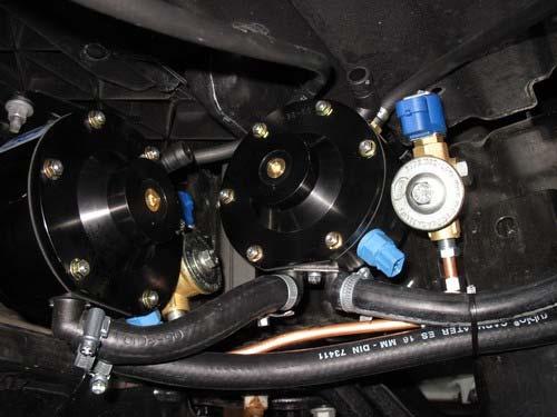
11 PAGE / Water connections 10

.")

12 PAGE / Overpressure connection Mount overpressure coupling to throttle body (see picture). Mount T-piece for overpressure hoses near reducers and connect to overpressure coupling. 11

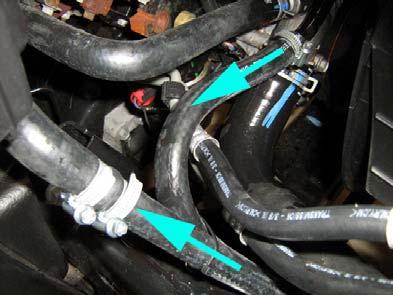
13 PAGE / Petrol injector power supply interruption Remove the inlet manifold. Connect VSI wires 26 & 27. Interrupt the petrol injector power supply ( + ). 12

14 PAGE / Overview inlet manifold couplings Bank 1 13


15 PAGE / Mounting the inlet manifold couplings Bank 1 Remove the inlet manifold. Use a petrol injector to determine were to drill the holes. Drill 8 holes of 5 mm in the inlet manifold. Cut M6x1 thread in these holes. Place the VSI couplings with a lock compound in the inlet manifold. Watch out that the lock compound doesn t come inside the VSI couplings. Connect VSI wires 26 & 27. Interrupt the petrol injector power supply ( + ). Mount the hoses on the VSI couplings and place the inlet manifold back on the engine. 14

16 PAGE / Overview inlet manifold couplings Bank 2 15


17 PAGE / Mounting the inlet manifold couplings Bank 2 Remove the inlet manifold. Use a petrol injector to determine were to drill the holes. Drill 8 holes of 5 mm in the inlet manifold. Cut M6x1 thread in these holes. Place the VSI couplings with a lock compound in the inlet manifold. Watch out that the lock compound doesn t come inside the VSI couplings. Connect VSI wires 26 & 27. Interrupt the petrol injector power supply ( + ). Mount the hoses on the VSI couplings and place the inlet manifold back on the engine. 16

18 PAGE / VSI injector rail overview 17


19 PAGE / Mounting the VSI injector rail Bank 1 18


20 PAGE / Mounting the VSI injector rail Bank 2 19

21 PAGE / Mounting the filter units Filter replacement must be recorded in the service book supplied LPG hoses Length of hose, ø 16 mm reducer -> filter unit Prins = ± 8 cm (2x) Length of hose, ø 5 mm reducer -> Y piece -> inlet manifold = ± 140 cm Length of hose, ø 11 mm filter unit Prins -> filter unit Prins = ± 20 cm Length of hose, ø 11 mm filter unit Prins -> rail B2 = ± 142 cm Length of hose, ø 11 mm filter unit Prins -> rail B1 = ± 115 cm Length of hose, ø 5 mm VSI injector 1 -> manifold coupling = ± 29 cm Length of hose, ø 5 mm VSI injector 2 -> manifold coupling = ± 24 cm Length of hose, ø 5 mm VSI injector 3 -> manifold coupling = ± 17 cm Length of hose, ø 5 mm VSI injector 4 -> manifold coupling = ± 20 cm Length of hose, ø 5 mm VSI injector 5 -> manifold coupling = ± 23 cm Length of hose, ø 5 mm VSI injector 6 -> manifold coupling = ± 20 cm Length of hose, ø 5 mm VSI injector 7 -> manifold coupling = ± 28 cm Length of hose, ø 5 mm VSI injector 8 -> manifold coupling = ± 29 cm Cut the hoses on length. Please observe that there is no damage or fouling to the hoses. 20


22 PAGE / Mounting the VSI computer Never mount the computer upside down or near a heat source 21


23 PAGE / Mount the switch. Mounting the fuel selection switch When mounting the switch, only push on its sides. Pushing the switch in the centre may result in damage to the switch. See general manual for programming the selection switch 22
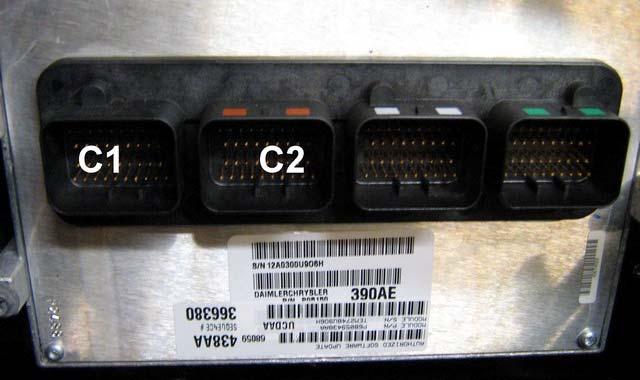
24 PAGE / ECU location 23
25 PAGE / ECU pin outs 24
26 PAGE / Electrical connections Check and measure the wiring in case of changes in the cars wiring colours. Mount filter unit plug to 1 of the 2 filters / Mount ECT plug to 1 of the 2 reducers. Wire number / code Wire colour Connection 50 MAIN GND brown Wire colour: BLACK Wire location: ECU, black connector C1, pos V BAT red Wire colour: RED Wire location: ECU, black connector C1, pos 29. Do not place the fuse in the holder before having completed the installation of the LPG system G INJ OUT 1 Green - white Connector VSI-injector to cylinder G INJ A PLUS red 32 32G INJ OUT 2 Green - white Connector VSI-injector to cylinder G INJ A PLUS red 31 31G INJ OUT 3 Green - white Connector VSI-injector to cylinder G INJ A PLUS red 30 30G INJ OUT 4 Green - white Connector VSI-injector to cylinder G INJ A PLUS red 5 5G INJ OUT 5 Green - white Connector VSI-injector to cylinder G INJ A PLUS red 4 4G INJ OUT 6 Green - white Connector VSI-injector to cylinder G INJ A PLUS red 3 3G INJ OUT 7 Green - white Connector VSI-injector to cylinder G INJ A PLUS red 2 2G INJ OUT 8 Green - white Connector VSI-injector to cylinder G INJ A PLUS red 13 IGNITION + Grey-white Make a connection to + petrol injector, in parallel with the vsi wire 26. Wire colour : RED Wire location : VSI wiring loom, nr.26, petrol injector power supply interruption. Or : Wire colour : BROWN-WHITE, +petrol injector. Wire location : near connector petrol injector. 46 LAMBDA 1-L orange For the measurement of the lambda signal of cylinder bank 1. Connect the wire in parallel to the lambda sensor. Wire colour : light BLUE-dark BLUE Wire location : ECU, orange connector C2, pos LAMBDA 2-R orange-white For the measurement of the lambda signal of cylinder bank 2. Connect the wire in parallel to the lambda sensor. Wire colour : BLUE-GREEN Wire location : ECU, orange connector C2, pos RPM Purple-white For measuring the engine speed. Wire color :GREY-BLUE Wire location : ECU, orange connector C2, pos 34 25


27 PAGE / Injection module connections 26
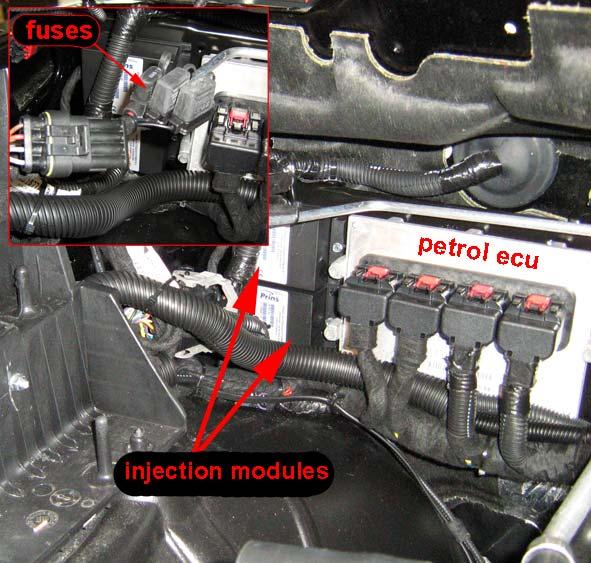
28 PAGE / Electrical connections Check and measure the wiring in case of changes in the cars wiring colours. VSI wire: 54 INJ module red - black Power supply for the simulation of the injector(s). Connect the red - black cable (54) to the loose red cable of the injector simulator(s). For the connection of the injector simulator the control cables of the petrol injectors must be interrupted. Connect the red cables of the module to the injector side and the black cables of the module to the computer side ( with corresponding yellow-white wire ). Do not interchange the red and the black cables, but connect those as a pair to each of the injectors (refer to the injector diagram). Module location: right side petrol ecu. 27
29 PAGE / Electrical connections Check and measure the wiring in case of changes in the cars wiring colours. For measuring the petrol injectors. Connect each yellow / white measuring cable to the position at which the control cables of the petrol injectors have been interrupted (refer to the injector diagram). Attention: Each yellow / white measuring cable corresponds to a specific LPG injector and cylinder number. Do not interchange the cables. Refer to the page 'mounting the injector rail' for the correct cylinder numbers. VSI measure wire nr. : Full colored / Bicolored To interrupt petrol injector wire color / location VSI wire nr. 39 Petrol injector / cyl. 1 Yellow-white Color :brown-yellow Location : ECU, orange connector C2, pos 14 VSI wire nr. 38 Petrol injector / cyl. 2 Yellow-white Color : brown-blue Location : ECU, orange connector C2, pos 13 VSI wire nr. 37 Petrol injector / cyl. 3 Yellow-white Color : brown-light blue Location : ECU, orange connector C2, pos 12 VSI wire nr. 36 Petrol injector / cyl. 4 Yellow-white Color : brown-tan Location : ECU, orange connector C2, pos 11 VSI wire nr. 11 Petrol injector / cyl. 5 Yellow-white Color :brown-orange Location : ECU, orange connector C2, pos 5 VSI wire nr. 10 Petrol injector / cyl. 6 Yellow-white Color : brown-purple Location : ECU, orange connector C2, pos 4 VSI wire nr. 9 Yellow-white Color : brown-yellow Petrol injector / cyl. 7 Location : ECU, black connector C1, pos 5 VSI wire nr. 8 Yellow-white Color : brown-blue Petrol injector / cyl. 8 Location : ECU, black connector C1, pos 4 RED-BLACK YELLOW-WHITE 54 VSI COMPUTER RED RED INJECTOR SIMULATOR BLACK RED RED-WHITE GREEN-WHITE RED - + VSI INJECTOR PETROL INJECTOR interrupt the power supply of each injector 28
30 PAGE / Checklist after installation 1. Connect the serial interface wire and run the VSI diagnosis program. Install the VSI fuse, and program the switch. Turn the ignition key in the accessory position. When working on the car, beware of moving and rotating parts in the engine compartment. 2. When commissioning the LPG system, you must activate the VSI computer with the diagnosis software. When the VSI computer has not been activated, it will keep generating error code 160. To activate the VSI computer, select function F11 (activate ECM). 3. Check whether the program in the VSI computer matches with the car ( dedicated engine set ): Refer with F2 to the box number and car description in the diagnosis software and compare these with the set number. 4. The system will switch over to LPG as soon as the temperature of the coolant (T-ect) becomes higher than the parameter T-min set and when the TSO-cold time is expired. 5. Check all components and connections for any gas leakage ( use a LPG leak detector device or a fluid detection like soap. Caution for moving and rotating parts in the engine compartment! 6. Let the engine run warm on petrol >80 C. Check if the reducer heats up. Check the engine signals, petrol injection time, RPM, ECT, lambda Let the engine run idle on LPG. Adjust the reducer pressure. Refer to the parameter list ( or F2 : ID box) for the idle level value set. Adjust the reducer pressure in such a way that the pressure measured ( P-sys ) equals the idle level value. Turn the socket-head screw at the front of the reducer to adjust the pressure. An error code will be generated whenever the pressure variation is to high. Seal the reducer with the sticker included in the delivery after having adjusted the pressure. 7. Use the diagnosis software to check again all input and output signals. 8. Check the system for error codes and solve these, if required. Check the petrol MMS for EOBD error codes. Place the protection connector on the VSI communication connector. 9. Make a test drive and check the drivability on LPG and petrol. 29
31 PAGE / Trouble code chart Trouble code Definition Check / solution 100 Lambda to long to rich. Check when operating on petrol and LPG that there is good lambda signal movement. 101 Lambda to long to lean. Check when operating on petrol and LPG that there is good lambda signal movement. Check when operating on petrol and LPG that there is good lambda signal movement. 102 Lambda to long to lean during open loop. 110 T-ECT>= 171 C Check if the ECT sensor (blue) in the reducer is connector is connected to ground. 111 T-ECT>= -40 C Check if the ECT sensor (blue) in the reducer has a power connection. 120 T-LPG>= 171 C Check the ground connection of the Pressure/temperature sensor in the filter unit. 121 T-LPG>= -40 C Check the power connection of the Pressure/temperature sensor in the filter unit. 150 Psys<= Low_Level Based on a pressure drop in the system, this can be caused by an empty LPG tank, incorrect solenoid valve, polluted filter or incorrectly adjusted pressure. 160 ECM-VSI not activated Activate the LPG computer with the diagnostic program, using the F11 function key. 180 T-Board >= 90 C LPG computer circuit board to hot, replace the VSI computer in a cooler area. 181 Battery voltage to high Check board voltage / alternator output and condition of the battery VSI injector Injector current to high, check for short circuiting 280 overload VSI injector noload Injector current to low, check for bad connections. 310 Adjusted pressure on idle out of Adjust the idle pressure to the value shown by parameter Idle Level range 311 Programm error during flahing the Check parameter settings, contact Prins Autogassystemen. memory 320 Psys voltage to low Check the ground connection of the Pressure/temperature sensor in the filter unit. 321 Psys voltage to high Check the power connection of the Pressure/temperature sensor in the filter unit. 322 Psys > 3,5 Bar Check the coolant temperature (T-ect) and the reducer for leakage of the first stage. 330 unexpected parameter change Contact Prins Autogassystemen. 340 reducer warms up to slow Check the water connections / circuit. 341 Gas leakage, system pressure is less then Check the system for gasleakage bar after 4 hours when the engine is not running - System switches to LPG but engine stalls immediately. LPG tank empty? Lock-off valves open? - No injection timing on LPG ( 0 Check the injection module. Msec.) - The LPG system switches constantly between LPG and Petrol - Check coolant system for air. - T-ect sensor in the reducer malfunction. - Engine hesitates on high revs, and not running on all cylinders. Engine runs good on idle. Check for kinked or jammed LPG hoses (between VSI injector and couplings). Check for blocked inlet couplings. - Switch LED s don t lit up Check the main fuse of the VSI system Check ignition+ (VSI wire 13) - Fault codes when turning the ignition off ( key out the ignition ) Caused by different switch off times between ignition+ and injector power. Connect VSI wire 13 to the petrol injector feed instead of ignition+. - The orange LED on the switch flashes Activate the LPG computer with the diagnostic program, using the F11 function key. - The LPG system switches to LPG LPG tank empty? but engine stalls immediately - Not running on all cylinders on lpg Check parameter 10, number of cylinders. - No injection times on lpg Check the connections of the injection module. - Injection time falls to 0 msec on Check the injection module. LPG - Check engine while running on LPG, Replace injection module injector circuit malfunction, no lambda control (limb home) - Not starting / running on petrol Check the connections of the injection module. 30
MAKE OF AUTOMOBILE: MODEL YEAR: 2004 SYSTEM APPROVAL NUMBER ( R115 ) ENGINE SET NUMBER 336/
 ENGINE SET NUMBER 336/") MAKE OF AUTOMOBILE: TYPE: A4 PISTON DISPLACEMENT: 1800 NUMBER OF VALVES: 20V ENGINE NUMBER: BFB TRANSMISSION TYPE ( MT / AT ) AT VEHICLE CATEGORIES M or N M TYPE VSI INJECTOR ( NUMBER + COLOR ) YELLOW
MAKE OF AUTOMOBILE: TYPE: A4 PISTON DISPLACEMENT: 1800 NUMBER OF VALVES: 20V ENGINE NUMBER: BFB TRANSMISSION TYPE ( MT / AT ) AT VEHICLE CATEGORIES M or N M TYPE VSI INJECTOR ( NUMBER + COLOR ) YELLOW
MAKE OF AUTOMOBILE: MODEL YEAR: 2007 SYSTEM APPROVAL NUMBER ( R115 ) R ENGINE SET NUMBER 349/
 R ENGINE SET NUMBER 349/") MAKE OF AUTOMOBILE: KIA TYPE: CARENS PISTON DISPLACEMENT: 2000 NUMBER OF VALVES: 16 ENGINE NUMBER: G4KA TRANSMISSION TYPE ( MT / AT ) MT VEHICLE CATEGORIES M or N M TYPE VSI INJECTOR ( COLOUR ) ORANGE
MAKE OF AUTOMOBILE: KIA TYPE: CARENS PISTON DISPLACEMENT: 2000 NUMBER OF VALVES: 16 ENGINE NUMBER: G4KA TRANSMISSION TYPE ( MT / AT ) MT VEHICLE CATEGORIES M or N M TYPE VSI INJECTOR ( COLOUR ) ORANGE
MODEL YEAR: 2010 SYSTEM APPROVAL NUMBER ( R115 ) R ENGINE SET NUMBER 349/ (.06 /.07 )
 R ENGINE SET NUMBER 349/ (.06 /.07 )") MAKE OF AUTOMOBILE: TYPE: IX35 PISTON DISPLACEMENT: 2000 NUMBER OF VALVES: 16 ENGINE NUMBER: G4KD TRANSMISSION TYPE ( MT / AT ) MT VEHICLE CATEGORIES M or N M TYPE VSI INJECTOR ( COLOUR ) Orange VERSION
MAKE OF AUTOMOBILE: TYPE: IX35 PISTON DISPLACEMENT: 2000 NUMBER OF VALVES: 16 ENGINE NUMBER: G4KD TRANSMISSION TYPE ( MT / AT ) MT VEHICLE CATEGORIES M or N M TYPE VSI INJECTOR ( COLOUR ) Orange VERSION
MAKE OF AUTOMOBILE: PISTON DISPLACEMENT: 1300
 MAKE OF AUTOMOBILE: TYPE: YARIS PISTON DISPLACEMENT: 1300 NUMBER OF VALVES: 16 VVT-I ENGINE NUMBER: 2SZ-FE TRANSMISSION TYPE ( MT / AT ) AT VEHICLE CATEGORIES M or N M TYPE VSI INJECTOR ( NUMBER + COLOR
MAKE OF AUTOMOBILE: MODEL YEAR: 2007 SYSTEM APPROVAL NUMBER ( R115 ) VSI-LPG 10 ENGINE SET NUMBER 364/
 VSI-LPG 10 ENGINE SET NUMBER 364/") MAKE OF AUTOMOBILE: TYPE: FABIA PISTON DISPLACEMENT: 1400 NUMBER OF VALVES: 16 ENGINE NUMBER: BUD TRANSMISSION TYPE ( MT / AT ) MT VEHICLE CATEGORIES M or N M TYPE VSI INJECTOR ( NUMBER + COLOR ) 180/30410
MAKE OF AUTOMOBILE: TYPE: FABIA PISTON DISPLACEMENT: 1400 NUMBER OF VALVES: 16 ENGINE NUMBER: BUD TRANSMISSION TYPE ( MT / AT ) MT VEHICLE CATEGORIES M or N M TYPE VSI INJECTOR ( NUMBER + COLOR ) 180/30410
MAKE OF AUTOMOBILE: 316 / 318i E46 NUMBER OF VALVES:
 MAKE OF AUTOMOBILE: TYPE: 316 / 318i E46 PISTON DISPLACEMENT: 1800 2000 cc NUMBER OF VALVES: 16V ENGINE NUMBER: N42B18A / N42B20A TRANSMISSION TYPE ( MT / AT ) MT VEHICLE CATEGORIES M or N M TYPE VSI INJECTOR
MAKE OF AUTOMOBILE: ENGINE SET NUMBER 348/
 MAKE OF AUTOMOBILE: TYPE: CIVIC PISTON DISPLACEMENT: 1800 NUMBER OF VALVES: 16 ENGINE NUMBER: R18A TRANSMISSION TYPE ( MT / AT ) MT VEHICLE CATEGORIES M or N M TYPE VSI INJECTOR ( COLOR ) ORANGE VERSION
MODEL YEAR: SYSTEM APPROVAL NUMBER ( R115 ) R ENGINE SET NUMBER 354/
 R ENGINE SET NUMBER 354/") MAKE OF AUTOMOBILE: MERECEDES TYPE: E200 W211 PISTON DISPLACEMENT: 1796 NUMBER OF VALVES: 16 ENGINE NUMBER: M271 TRANSMISSION TYPE ( MT / AT ) AT VEHICLE CATEGORIES M or N M TYPE VSI INJECTOR ( NUMBER
MAKE OF AUTOMOBILE: MERECEDES TYPE: E200 W211 PISTON DISPLACEMENT: 1796 NUMBER OF VALVES: 16 ENGINE NUMBER: M271 TRANSMISSION TYPE ( MT / AT ) AT VEHICLE CATEGORIES M or N M TYPE VSI INJECTOR ( NUMBER
MAKE OF AUTOMOBILE: GRAND CHEROKEE PISTON DISPLACEMENT: 5700 NUMBER OF VALVES: 16
 MAKE OF AUTOMOBILE: TYPE: GRAND CHEROKEE PISTON DISPLACEMENT: 5700 NUMBER OF VALVES: 16 ENGINE NUMBER: 5.7V8 HEMI TRANSMISSION TYPE ( MT / AT ) AT VEHICLE CATEGORIES M or N M TYPE VSI INJECTOR ( NUMBER
MAKE OF AUTOMOBILE: ENGINE SET NUMBER 366/
 MAKE OF AUTOMOBILE: TYPE: SORENTO PISTON DISPLACEMENT: 3300 NUMBER OF VALVES: 24 ENGINE NUMBER: G6DB TRANSMISSION TYPE ( MT / AT ) MT VEHICLE CATEGORIES M or N M TYPE VSI INJECTOR ( NUMBER + COLOR ) 180/30340
MAKE OF AUTOMOBILE: PISTON DISPLACEMENT: 8300 NUMBER OF VALVES: 20 TRANSMISSION TYPE ( MT / AT ) TYPE VSI INJECTOR (COLOR ) VERSION ( LPG / CNG )
 TYPE VSI INJECTOR (COLOR ) VERSION ( LPG / CNG )") MAKE OF AUTOMOBILE: TYPE: PISTON DISPLACEMENT: 8300 NUMBER OF VALVES: 20 ENGINE NUMBER: SRT V10 Viper TRANSMISSION TYPE ( MT / AT ) AT TYPE VSI INJECTOR (COLOR ) YELLOW VERSION ( LPG / CNG ) LPG INJECTION
MAKE OF AUTOMOBILE: TYPE: PISTON DISPLACEMENT: 8300 NUMBER OF VALVES: 20 ENGINE NUMBER: SRT V10 Viper TRANSMISSION TYPE ( MT / AT ) AT TYPE VSI INJECTOR (COLOR ) YELLOW VERSION ( LPG / CNG ) LPG INJECTION
MAKE OF AUTOMOBILE: PISTON DISPLACEMENT: 2700 NUMBER OF VALVES:
 MAKE OF AUTOMOBILE: DODGE TYPE: JOURNEY PISTON DISPLACEMENT: 2700 NUMBER OF VALVES: 24V ENGINE NUMBER: 2.7V6 EER TRANSMISSION TYPE ( MT / AT ) AT VEHICLE CATEGORIES M or N M TYPE VSI INJECTOR ( COLOR )
MAKE OF AUTOMOBILE: ENGINE SET NUMBER 337/
 MAKE OF AUTOMOBILE: TYPE: NITRO PISTON DISPLACEMENT: 3700 NUMBER OF VALVES: 12V ENGINE NUMBER: V6 TRANSMISSION TYPE ( MT / AT ) AT VEHICLE CATEGORIES M or N M TYPE VSI INJECTOR ( NUMBER + COLOR ) 180/30330
MODEL YEAR: 2009 SYSTEM APPROVAL NUMBER ( R115 ) R ENGINE SET NUMBER 350/
 R ENGINE SET NUMBER 350/") MAKE OF AUTOMOBILE: TYPE: PRIORA 2170 / 2172 PISTON DISPLACEMENT: 1600 NUMBER OF VALVES: 16 ENGINE NUMBER: 21126 TRANSMISSION TYPE ( MT / AT ) MT VEHICLE CATEGORIES M or N M TYPE VSI INJECTOR (COLOR )
MAKE OF AUTOMOBILE: TYPE: PRIORA 2170 / 2172 PISTON DISPLACEMENT: 1600 NUMBER OF VALVES: 16 ENGINE NUMBER: 21126 TRANSMISSION TYPE ( MT / AT ) MT VEHICLE CATEGORIES M or N M TYPE VSI INJECTOR (COLOR )
MODEL YEAR: 2007 SYSTEM APPROVAL NUMBER ( R115 ) R ENGINE SET NUMBER 350/
 R ENGINE SET NUMBER 350/") MAKE OF AUTOMOBILE: TYPE: KALINA 1117/ 1118 / 1119 PISTON DISPLACEMENT: 1600 NUMBER OF VALVES: 8 ENGINE NUMBER: 21114 TRANSMISSION TYPE ( MT / AT ) MT VEHICLE CATEGORIES M or N M TYPE VSI INJECTOR ( NUMBER
MAKE OF AUTOMOBILE: TYPE: KALINA 1117/ 1118 / 1119 PISTON DISPLACEMENT: 1600 NUMBER OF VALVES: 8 ENGINE NUMBER: 21114 TRANSMISSION TYPE ( MT / AT ) MT VEHICLE CATEGORIES M or N M TYPE VSI INJECTOR ( NUMBER
PISTON DISPLACEMENT: 1200 NUMBER OF VALVES: ENGINE NUMBER: TRANSMISSION TYPE ( MT / AT ) VEHICLE CATEGORIES M or N TYPE VSI INJECTOR (COLOUR )
 VEHICLE CATEGORIES M or N TYPE VSI INJECTOR (COLOUR )") MAKE OF AUTOMOBILE: VOLKSWAGEN TYPE: POLO PISTON DISPLACEMENT: 1200 NUMBER OF VALVES: 8V ENGINE NUMBER: BZG TRANSMISSION TYPE ( MT / AT ) MT VEHICLE CATEGORIES M or N M TYPE VSI INJECTOR (COLOUR ) BLUE
MAKE OF AUTOMOBILE: VOLKSWAGEN TYPE: POLO PISTON DISPLACEMENT: 1200 NUMBER OF VALVES: 8V ENGINE NUMBER: BZG TRANSMISSION TYPE ( MT / AT ) MT VEHICLE CATEGORIES M or N M TYPE VSI INJECTOR (COLOUR ) BLUE
MAKE OF AUTOMOBILE: ENGINE SET NUMBER 345/ NUMBER : 076/ DATE : VERSION NR : B
 MAKE OF AUTOMOBILE: TYPE: LOGAN PISTON DISPLACEMENT: 1600 NUMBER OF VALVES: 8 ENGINE NUMBER: K7M 710 TRANSMISSION TYPE ( MT / AT ) MT VEHICLE CATEGORIES M or N ( M ) TYPE VSI INJECTOR ( NUMBER + COLOR
MAKE OF AUTOMOBILE: TYPE: 508 PISTON DISPLACEMENT: NUMBER OF VALVES: FIRING ORDER: TRANSMISSION TYPE ( MT / AT ) VEHICLE CATEGORIES M or N
 VEHICLE CATEGORIES M or N") MAKE OF AUTOMOBILE: Peugeot TYPE: 508 PISTON DISPLACEMENT: 1600cc NUMBER OF VALVES: 16v ENGINE NUMBER: EP6CDT 115kW FIRING ORDER: 1-3-4-2 TRANSMISSION TYPE ( MT / AT ) MT VEHICLE CATEGORIES M or N M TYPE
MAKE OF AUTOMOBILE: Peugeot TYPE: 508 PISTON DISPLACEMENT: 1600cc NUMBER OF VALVES: 16v ENGINE NUMBER: EP6CDT 115kW FIRING ORDER: 1-3-4-2 TRANSMISSION TYPE ( MT / AT ) MT VEHICLE CATEGORIES M or N M TYPE
MAKE OF AUTOMOBILE: TYPE: V 70 PISTON DISPLACEMENT: 2521 NUMBER OF VALVES:
 MAKE OF AUTOMOBILE: TYPE: V 70 PISTON DISPLACEMENT: 2521 NUMBER OF VALVES: 20V ENGINE NUMBER: B5254T TRANSMISSION TYPE ( MT / AT ) AT VEHICLE CATEGORIES M or N PASSENGER CAR ( M ) TYPE VSI INJECTOR (COLOUR
MAKE OF AUTOMOBILE: PISTON DISPLACEMENT: NUMBER OF VALVES: ENGINE NUMBER: TRANSMISSION TYPE ( MT / AT ) VEHICLE CATEGORIES M or N PERSONEN AUTO ( M )
 VEHICLE CATEGORIES M or N PERSONEN AUTO ( M )") MAKE OF AUTOMOBILE: TYPE: WRANGLER PISTON DISPLACEMENT: 4000 cc NUMBER OF VALVES: 12 v ENGINE NUMBER: M3 TJ TRANSMISSION TYPE ( MT / AT ) MT VEHICLE CATEGORIES M or N PERSONEN AUTO ( M ) TYPE VSI INJECTOR
MAKE OF AUTOMOBILE: TYPE: WRANGLER PISTON DISPLACEMENT: 4000 cc NUMBER OF VALVES: 12 v ENGINE NUMBER: M3 TJ TRANSMISSION TYPE ( MT / AT ) MT VEHICLE CATEGORIES M or N PERSONEN AUTO ( M ) TYPE VSI INJECTOR
MAKE OF AUTOMOBILE: PISTON DISPLACEMENT: 1600 NUMBER OF VALVES: 16
 MAKE OF AUTOMOBILE: TYPE: MERIVA PISTON DISPLACEMENT: 1600 NUMBER OF VALVES: 16 ENGINE NUMBER: Z16XEP TRANSMISSION TYPE ( MT / AT ) MT VEHICLE TYPE M TYPE VSI INJECTOR ( NUMBER + COLOR ) 180/30430 ORANGE
MANUFACTURER Explorer Sport ENGINE DISPLACEMENT NUMBER OF VALVES FIRING ORDER VEHICLE CATEGORIES TRANSMISSION
 MANUFACTURER Ford TYPE Explorer Sport ENGINE DISPLACEMENT 3500cc NUMBER OF VALVES 24v ENGINE CODE / NUMBER 3.5L GTDi Ecoboost FIRING ORDER 1 4 2 5-3 - 6 VEHICLE CATEGORIES M TRANSMISSION AT VERSION AFC-2.1
MANUFACTURER TYPE F-150 ENGINE DISPLACEMENT NUMBER OF VALVES FIRING ORDER VEHICLE CATEGORIES TRANSMISSION
 MANUFACTURER Ford TYPE F-150 ENGINE DISPLACEMENT 3500cc NUMBER OF VALVES 24v ENGINE CODE / NUMBER - OUTPUT 3.5L EcoBoost 2015 365hp FIRING ORDER 1-4-2-5-3-6 VEHICLE CATEGORIES M TRANSMISSION AT VERSION
ENGINE DISPLACEMENT 2000 NUMBER OF VALVES 16 ENGINE SET NUMBER
 MANUFACTURER Subaru TYPE Forester ENGINE DISPLACEMENT 2000 NUMBER OF VALVES 16 ENGINE CODE / NUMBER FA20 DIT VEHICLE CATEGORIES M TRANSMISSION AT VERSION Direct LiquiMax-2.1 PETROL ECU MANUFACTURER / CODE
ENGINE DISPLACEMENT NUMBER OF VALVES 16 VEHICLE CATEGORIES
 MANUFACTURER Dacia TYPE Duster ENGINE DISPLACEMENT 1200cc NUMBER OF VALVES 16 ENGINE CODE / NUMBER H5F (TCe125) VEHICLE CATEGORIES M TRANSMISSION MT (6-speed) VERSION AFC-2.1 PETROL ECU MANUFACTURER /
ENGINE DISPLACEMENT NUMBER OF VALVES ENGINE SET NUMBER VEHICLE CATEGORIES. Direct LiquiMax-2.0 PETROL ECU MANUFACTURER / CODE Bosch MED 17.
 MANUFACTURER VOLVO TYPE V60 / V70 T4F ENGINE DISPLACEMENT 1600cc NUMBER OF VALVES 16v ENGINE CODE / NUMBER B4164T2 VEHICLE CATEGORIES M TRANSMISSION MT/AT VERSION Direct LiquiMax-2.0 PETROL ECU MANUFACTURER
Megane Estate ENGINE DISPLACEMENT NUMBER OF VALVES VEHICLE CATEGORIES
 MANUFACTURER Renault TYPE Megane Estate ENGINE DISPLACEMENT 1200cc NUMBER OF VALVES 16v ENGINE CODE / NUMBER H5F (TCe115) VEHICLE CATEGORIES M TRANSMISSION MT(6) VERSION AFC-2.1 PETROL ECU MANUFACTURER
Prins autogassystemen b.v. Veldhoven
 Prins autogassystemen b.v. Veldhoven MOUNTING INSTRUCTION ENGINE CONVERSION SET MAKE OF AUTOMOBILE: TYPE: ASTRA PISTON DISPLACEMENT: 2000 cc MT NUMBER OF VALVES: 16V ENGINE NUMBER: X20XEV INJECTION SYSTEM:
MAKE OF AUTOMOBILE: NUMBER : 076/ DATE : Copyright Prins Autogassystemen B.V VERSION NR : B
 MAKE OF AUTOMOBILE: Ford TYPE: Mondeo PISTON DISPLACEMENT: 2000 NUMBER OF VALVES: 16 ENGINE NUMBER: AOBA TYPE VSI INJECTOR ( COLOR ) Yellow MODEL YEAR: 2010 ENGINE SET NUMBER 347/1810500.07 NUMBER : 076/0703201
Universal instructions CNG Tank-sets. MODEL year 2011 SET Number. NUMMER : DATE : Copyright Prins Autogassystemen B.V VERSIE NR : DB
 Universal instructions CNG Tank-sets Make universal MODEL year 2011 SET Number all NUMMER : DATE : 2011-09-12 TABLE OF CONTENTS... 1 Required equipment / tools / materials for installing a complete system...
Required equipment / tools / materials for installing a complete system. Vehicle check
 2-2017 Table of contents Required equipment / tools / materials for installing a complete system 3 Vehicle check 3 General instructions 4 Tightening moments 5 Direct LiquiMax Gen1 & Gen2 components 6 Approval
DATE : VERSION NR :
 DATE : 07032006 VERSION NR : B Table of contents General instructions 2 Introduction 3 Overview VSI system 4 Approval numbers VSI components 4 The ucer 5 The injector rail 6 The filter unit 7 The VSI computer
MAKE OF AUTOMOBILE: MODEL YEAR: 2010 SYSTEM APPROVAL NUMBER ( R115 ) BOOT SET NUMBER 947/
 BOOT SET NUMBER 947/") MAKE OF AUTOMOBILE: FORD TYPE: MONDEO TANK CAPACITY: 61 Liter WvM toroidal TANK LOCATION SPARE WHEEL ROOM MODEL YEAR: 2010 SYSTEM APPROVAL NUMBER ( R115 ) R115-0000** BOOT SET NUMBER 947/1810501 NUMBER:
MAKE OF AUTOMOBILE: FORD TYPE: MONDEO TANK CAPACITY: 61 Liter WvM toroidal TANK LOCATION SPARE WHEEL ROOM MODEL YEAR: 2010 SYSTEM APPROVAL NUMBER ( R115 ) R115-0000** BOOT SET NUMBER 947/1810501 NUMBER:
MAKE OF AUTOMOBILE: MODEL YEAR: SYSTEM APPROVAL NUMBER ( R115 ) E4-115R /-17 / DLM-LPG 01/10 MANUAL NUMBER: 076/ DATE
 E4-115R /-17 / DLM-LPG 01/10 MANUAL NUMBER: 076/ DATE") MAKE OF AUTOMOBILE: HYUNDAI TYPE: ix35 TANK CAPACITY: 74 Liter Fuel Module Stako toroidal TANK LOCATION SPARE WHEEL ROOM MODEL YEAR: 2010 SYSTEM APPROVAL NUMBER ( R115 ) E4-115R-0000-04/-17 / DLM-LPG 01/10
MAKE OF AUTOMOBILE: HYUNDAI TYPE: ix35 TANK CAPACITY: 74 Liter Fuel Module Stako toroidal TANK LOCATION SPARE WHEEL ROOM MODEL YEAR: 2010 SYSTEM APPROVAL NUMBER ( R115 ) E4-115R-0000-04/-17 / DLM-LPG 01/10
MAKE OF AUTOMOBILE: MODEL YEAR: 2013 SYSTEM APPROVAL NUMBER ( R115 ) R MANUAL NUMBER: 076/ DATE
 R MANUAL NUMBER: 076/ DATE") MAKE OF AUTOMOBILE: Dacia TYPE: Lodgy TANK CAPACITY: 59 Liter Stako toroidal TANK LOCATION Spare Wheel Room / Underneath MODEL YEAR: 2013 SYSTEM APPROVAL NUMBER ( R115 ) R115-000013 BOOT SET NUMBER 345/070002/A
MAKE OF AUTOMOBILE: Dacia TYPE: Lodgy TANK CAPACITY: 59 Liter Stako toroidal TANK LOCATION Spare Wheel Room / Underneath MODEL YEAR: 2013 SYSTEM APPROVAL NUMBER ( R115 ) R115-000013 BOOT SET NUMBER 345/070002/A
MAKE OF AUTOMOBILE: GRAND VOYAGER STOW`N GO MODEL YEAR: NUMBER: 076/ Copyright Prins Autogassystemen B.V DATE:
 MAKE OF AUTOMOBILE: CHRYSLER TYPE: GRAND VOYAGER STOW`N GO TANK CAPACITY: 2X 36Liter Stako toroidal TANK LOCATION FRONT SEAT ROOM MODEL YEAR: NUMBER: 076/3211036 Copyright Prins Autogassystemen B.V. 2008
Installation And Programming Manual of OPTIMA Eco Tec and OPTIMA Pro Tec OBD/CAN
 v1.03 [EN] Installation And Programming Manual of OPTIMA Eco Tec and OPTIMA Pro Tec OBD/CAN ALEX Zambrowska 4A, 16-001 Kleosin Poland tel./fax: +48 85 664 84 40 www.optimagas.pl e-mail: service@optimagas.pl
2002 ENGINE PERFORMANCE. Self-Diagnostics - RAV4. Before performing testing procedures, check for any related Technical Service Bulletins (TSBs).
.") 2002 ENGINE PERFORMANCE Self-Diagnostics - RAV4 INTRODUCTION NOTE: Before performing testing procedures, check for any related Technical Service Bulletins (TSBs). To properly diagnosis and repair this
2002 ENGINE PERFORMANCE Self-Diagnostics - RAV4 INTRODUCTION NOTE: Before performing testing procedures, check for any related Technical Service Bulletins (TSBs). To properly diagnosis and repair this
Powertrain DTC Summaries EOBD
 Powertrain DTC Summaries Quick Reference Diagnostic Guide Jaguar X-TYPE 2.0 L 2002.25 Model Year Refer to page 2 for important information regarding the use of Powertrain DTC Summaries. Jaguar X-TYPE 2.0
Turbocharger system. Note: Observe rules of cleanliness Page Charge air pressure control connection diagram Page 21-2.
 Page 1 of 50 21-1 Turbocharger system Note: Observe rules of cleanliness Page 21-22. Charge air pressure control connection diagram Page 21-2. All hose connections are secured with hose clamps: parts catalog.
WORLD LEADER IN ALTERNATIVE FUEL SYSTEMS CALIBRATION PARAMETERS
 WORLD LEADER IN ALTERNATIVE FUEL SYSTEMS CALIBRATION PARAMETERS VSI-2.0 LPG UNIVERSAL KIT Version: Back V2.4 to Parameter 03-2018 Overview Page 1 of 53 Copyright Prins Autogassystemen B.V. 2018 Back to
Fuel injection system, servicing
 24-1 Fuel injection system, servicing Component locations overview 1 - Oxygen sensor 1 before Three Way Catalyst G39 2 - Oxygen sensor 2 after Three Way Catalyst G130 3 - Engine Coolant Temperature sensor
DIAGNOSTIC TROUBLE CODE CHART HINT:
 DIAGNOSTICS DIAGNOSTIC TROUBLE CODE CHART HINT: SFI SYSTEM (1MZFE) 05241 Parameters listed in the chart may not be exactly the same as your reading due to the type of instrument or other factors. If a
Alternative Fuel Engine Control Unit
 1999 Chevrolet/Geo Cavalier (CNG) Alternative Fuel Engine Control Unit Table 1: AF ECU Function Parameters The (AF ECU) controls alternative fuel engine operation. The control unit monitors various engine
G - TESTS W/CODES - 2.2L
 G - TESTS W/CODES - 2.2L 1994 Toyota Celica 1994 ENGINE PERFORMANCE Toyota 2.2L Self-Diagnostics Celica INTRODUCTION If no faults were found while performing F - BASIC TESTING, proceed with self-diagnostics.
Powertrain DTC Summaries EOBD
 Powertrain DTC Summaries Quick Reference Diagnostic Guide Jaguar S-TYPE V6, V8 N/A and V8 SC 2002.5 Model Year Refer to pages 2 9 for important information regarding the use of Powertrain DTC Summaries.
DTC P0300-P0308. Diagnostic Instructions. DTC Descriptors. Circuit/System Description. Conditions for Running the DTC
 Page 1 of 5 2009 GMC Truck Sierra - 2WD Sierra, Silverado (VIN C/K) Service Manual Engine Engine Mechanical - 4.8L, 5.3L, 6.0L, 6.2L, or 7.0L Description and Operation DTC P0300-P0308 Diagnostic Instructions
Malfunction Criteria and Threshold Value Adaptive value. Secondary Parameters with Enable Conditions. >50.8 S Engine load 9-45% Delta fuel adaptation
 DTC Error Message P0171 System Too Lean (Bank 1) Diagnostic Procedure Check fuel pump delivery and quantity. Refer to page 126. Check Fuel pressure regulator and residual pressure. Refer to Fuel Injection
Preparing and programming of ESGI 2 LPG supply system manual
 Preparing and programming of ESGI 2 LPG supply system manual Part II Instruction of preparing and programming the ESGI system 1 Technical data of the central unit Vs Power supply voltage 0...16V V i_an
PowerJet Sequential Injection INDEX. 1 Introduction 1.1 Features of the Software. 2- Software installation
 INDEX 1 Introduction 1.1 Features of the Software 2- Software installation 3 Open the program 3.1 Language 3.2 Connection 4 Folder General - F2. 4.1 The sub-folder Error visualization 5 Folder Configuration
DIAGNOSTIC TROUBLE CODE CHART
 DIAGNOSTIC TROUBLE CODE CHART 05 35 HINT: As for the vehicle for MEXICO, refer to Repair Manual 2003 COROLLA MATRIX (Pub. No. RM940U). Parameters listed in the chart may not be exactly the same as your
Powertrain DTC Summaries OBD II
 Powertrain DTC Summaries Quick Reference Diagnostic Guide Jaguar X-TYPE 2.5L and 3.0L 2002 Model Year Revised January, 2002: P0706, P0731, P0732, P0733, P0734, P0735, P0740, P1780 POSSIBLE CAUSES Revised
TELORVEK EFI 5.0 Coyote Sequential Fuel Injection System Part # CY-11
 Page #1 TELORVEK EFI 5.0 Coyote Sequential Fuel Injection System Part # CY-11 WIRING INSTRUCTIONS Thank you for purchasing the absolute finest of wiring kits for the Ford Motor Co. Coyote modular engine.
H - TESTS W/O CODES Volvo 960 INTRODUCTION SYMPTOMS SYMPTOM DIAGNOSIS ENGINE PERFORMANCE Volvo Trouble Shooting - No Codes
 H - TESTS W/O CODES 1994 Volvo 960 1994 ENGINE PERFORMANCE Volvo Trouble Shooting - No Codes Volvo; 850, 940, 960 INTRODUCTION Before diagnosing symptoms or intermittent faults, perform steps in appropriate
2.8 Liter VR6 2V Fuel Injection & Ignition, Engine Code(s): AAA m.y
: AAA m.y") 2.8 Liter VR6 2V Fuel Injection & Ignition, Engine Code(s): AAA m.y. 1996-1997 01 - On Board Diagnostic (OBD) On Board Diagnostic (OBD II) Malfunction Indicator Lamp (MIL) On Board Diagnostic (OBD II),
2.8 Liter VR6 2V Fuel Injection & Ignition, Engine Code(s): AAA m.y. 1996-1997 01 - On Board Diagnostic (OBD) On Board Diagnostic (OBD II) Malfunction Indicator Lamp (MIL) On Board Diagnostic (OBD II),
LAMBDA SENSOR CONTROLLER
 LAMBDA SENSOR CONTROLLER INSTALLATION & PROGRAMMING MANUAL version : V1.77 -V1.79 Manufacturer: AC Spółka Akcyjna. 15-182 Białystok, ul. 27 Lipca 64, Poland tel. +48 85 7438148, fax +48 85 653 8649 www.ac.com.pl,
DTC P0171, P0172, P0174, or P0175
 Page 1 of 6 2009 Pontiac G8 G8 Service Manual Document ID: 2076050 DTC P0171, P0172, P0174, or P0175 Diagnostic Instructions Perform the Diagnostic System Check - Vehicle prior to using this diagnostic
DirectMount EXHAUST BRAKES
 DirectMount EXHAUST BRAKES APPLICATION: Fixed Orifice and PRXB Exhaust Brakes 2003 2005 Dodge Trucks with 3.5" & 4" Exhaust and 47RE & 48RE Automatic Transmissions Only Vehicles with an existing air compressor
INDEX 1 Introduction 2- Software installation 3 Open the program 4 General - F2 5 Configuration - F3 6 - Calibration - F5 7 Model - F6 8 - Map - F7
 SET UP MANUAL INDEX 1 Introduction 1.1 Features of the Software 2- Software installation 3 Open the program 3.1 Language 3.2 Connection 4 General - F2 4.1 The sub-folder Error visualization 5 Configuration
Secondary air system. Secondary air system, function/components
 Page 1 of 26 26-41 Secondary air system Secondary air system, function/components The secondary air system permits faster warm-up and thus makes the catalytic converter ready for operation sooner after
ENGINE COOLING GROUP CONTENTS GENERAL INFORMATION SERVICE SPECIFICATIONS COOLANT SEALANT THERMOSTAT...
 14-1 GROUP 14 CONTENTS GENERAL INFORMATION 14-2 SERVICE SPECIFICATIONS 14-2 COOLANT 14-3 SEALANT 14-3 DIAGNOSIS 14-3 INTRODUCTION 14-3 TROUBLESHOOTING STRATEGY 14-3 SYMPTOM CHART 14-3 SYMPTOM PROCEDURES
SAISBM V36W Installation Instructions
 The Original Secondary Air Injection System Bypass Kit SAISBM V36W Installation Instructions All Applicable Toyota/Lexus Vehicles Introduction: The Secondary Air Injection System (SAIS) bypass module is
1998 ENGINE PERFORMANCE. General Motors Corp. - Basic Diagnostic Procedures - 5.7L
 INTRODUCTION 1998 ENGINE PERFORMANCE General Motors Corp. - Basic Diagnostic Procedures - 5.7L The following diagnostic steps will help prevent overlooking a simple problem. This is also where to begin
ELECTRONIC FUEL INJECTION
 Table of Contents ELECTRONIC FUEL INJECTION Section 3B - Troubleshooting and Diagnostics TROUBLESHOOTING AND DIAGNOSTICS Specifications........................... 3B-1 Special Tools...........................
DI 3 ENGINE DIAGNOSTICS DI00H 22 PRE CHECK
 PRECHECK DI3 DI00H22 1. DIAGNOSIS SYSTEM (a) Description When troubleshooting OBD II vehicles, the only difference from the usual troubleshooting procedure is that you connect to the vehicle the OBD II
DIAGNOSTIC TROUBLE CODE CHART
 DIAGNOSTIC TROUBLE CODE CHART HINT: DI231 Parameters listed in the chart may not be exactly the same as your readings due to the type of instrument or other factors. If a malfunction code is displayed
Installation and Operation Guide. Tundra HD 2500 Power Inverter. for the. Webasto BlueCool Truck System
 Installation and Operation Guide Tundra HD 2500 Power Inverter for the Webasto BlueCool Truck System www.tundrainternational.com www.techwebasto.com BCTSP0063A Table of Contents 1. Introduction 4 1.1 Disclaimer.................................................................................
SPN 3227 or Suspect Parameter Number (SPN) and Failure Mode Indicator (FMI) Description
 and Failure Mode Indicator (FMI) Description") SPN 3227 or 3266 Suspect Parameter Number (SPN) and Failure Mode Indicator (FMI) Description SPN FMI Description Possible Causes 3227 4 EGO Bank A Sensor 2 Open or short to ground on Voltage Low signal
SPN 3227 or 3266 Suspect Parameter Number (SPN) and Failure Mode Indicator (FMI) Description SPN FMI Description Possible Causes 3227 4 EGO Bank A Sensor 2 Open or short to ground on Voltage Low signal
NATEF ENGINE PERFORMANCE CHECKLIST Name Date Period
 NATEF ENGINE PERFORMANCE CHECKLIST Name Period For every task in Engine Performance the following safety requirement must be strictly enforced: Comply with personal and environmental safety practices associated
Nero 6600H/6601H. Installation Guide. Commercial Vehicle Productivity and Security. Antenna Configuration
 Commercial Vehicle Productivity and Security The 6600H/6601H is a versatile and economical GPS tracking beacon designed for fleet management needs in all commercial vehicles. The H designation in the model
DIAGNOSTIC TROUBLE CODE DEFINITIONS
 DIAGNOSTIC TROUBLE CODE DEFINITIONS DIAGNOSTIC TROUBLE CODE DEFINITIONS DTC Description P0010 Variable Valve Timing Circuit Malfunction (Bank 1) P0020 Variable Valve Timing Circuit Malfunction (Bank 2)
3.4L V6 SUPERCHARGER 7 TH INJECTOR KIT
 Part Number: 00602-17620-260 00602-17620-261 00602-17620-263 00602-17620-264 00602-17620-274 00602-17620-275 00602-17620-276 Section I Installation Preparation Kit Contents Item # Quantity Reqd. Description
ENGINE COOLING GROUP CONTENTS GENERAL INFORMATION SERVICE SPECIFICATIONS COOLANT SEALANT THERMOSTAT...
 14-1 GROUP 14 CONTENTS GENERAL INFORMATION 14-2 SERVICE SPECIFICATIONS 14-2 COOLANT 14-3 SEALANT 14-3 DIAGNOSIS 14-3 INTRODUCTION 14-3 TROUBLESHOOTING STRATEGY 14-3 SYMPTOM CHART 14-3 SYMPTOM PROCEDURES
Kubota Engine Training: WG1605, spark ignited
 Kubota Engine Training: WG1605, spark ignited WG1605 Engine Training: System Overviews Mechanical Components Electronic Components and Sensors Operation Service Tool Fuel System Overview: Fuel System Overview:
Engine Cranks But Does Not Run
 Page 1 of 5 2000 GMC Truck GMC K Sierra - 4WD Sierra, Silverado, Suburban, Tahoe, Yukon (VIN C/K) Service Manual Engine Engine Controls - 4.8L, 5.3L, and 6.0L Diagnostic Information and Procedures Engine
DTC P0300 Random / Multiple Cylinder Misfire Detected. DTC P0301 Cylinder 1 Misfire Detected. DTC P0302 Cylinder 2 Misfire Detected
 1GR-FE EINE CONTROL SYSTEM SFI SYSTEM 169 DTC P0300 Random / Multiple Cylinder Misfire Detected DTC P0301 Cylinder 1 Misfire Detected DTC P0302 Cylinder 2 Misfire Detected DTC P0303 Cylinder 3 Misfire
ARTICLE BEGINNING INTRODUCTION SELF-DIAGNOSTIC SYSTEM RETRIEVING DTCS ENGINE PERFORMANCE Volkswagen Self-Diagnostics - Gasoline
 Article Text ARTICLE BEGINNING 1996 ENGINE PERFORMANCE Volkswagen Self-Diagnostics - Gasoline Cabrio, Golf III, GTI, Jetta III, Passat INTRODUCTION If no faults were found while performing preliminary
Powertrain DTC Summaries EOBD
 Powertrain DTC Summaries Quick Reference Diagnostic Guide Jaguar X-TYPE 2.5L and 3.0L 2001.5 Model Year Revised January, 2002: P0706, P0731, P0732, P0733, P0734, P0735, P0740, P1780 POSSIBLE CAUSES Revised
Electric wiring kit for towbars / 13-pin / 12 Volt / ISO 11446
 VOLVO V60 /00 >> S60 09/00 >> Part No: Electric wiring kit for towbars / -pin / Volt / ISO 446 This electric kit has to be installed by a professional workshop or a suitable qualified person. The installation
DTC P0300 Random / Multiple Cylinder Misfire Detected. DTC P0301 Cylinder 1 Misfire Detected. DTC P0302 Cylinder 2 Misfire Detected
 1GR-FE EINE CONTROL SYSTEM SFI SYSTEM 171 DTC P0300 Random / Multiple Cylinder Misfire Detected DTC P0301 Cylinder 1 Misfire Detected DTC P030 Cylinder Misfire Detected DTC P0303 Cylinder 3 Misfire Detected
VERSUS Installation manual Contents:
 VERSUS Installation manual Contents: 1. INTRODUCTION - SGI ECU VERSUS... 2 1.1. Initial recommendations... 2 1.2. Scheme no 1: General scheme of VERSUS system installation (4 cyl. engine sample)... 3 2.
Installation Instructions General Motors 8.1 Sequential Vapor Injection (S.V.I.) System 7500/6500 Series Trucks model year.
 System 7500/6500 Series Trucks model year.") Installation Instructions General Motors 8.1 Sequential Vapor Injection (S.V.I.) System 7500/6500 Series Trucks 2003-2005 model year. Technocarb Equipment (2004) Ltd. 4-30435 Progressive Way Abbotsford,
Installation Instructions General Motors 8.1 Sequential Vapor Injection (S.V.I.) System 7500/6500 Series Trucks 2003-2005 model year. Technocarb Equipment (2004) Ltd. 4-30435 Progressive Way Abbotsford,
Technical Installation Guide
 Technical Installation Guide ID Technical Document: DT_IS_GAI-005 Rev. Date Review n. Issued by Reviewed/ Approved 0 13/04/2007 First Issue Technical office ROS 1 19/02/2009 Second Issue Technical office
2002 Buick Rendezvous - AWD
 2002 Buick Rendezvous - AWD DTC P0410 Description The control module activates the secondary air injection (AIR) system by grounding both the pump relay and the vacuum control solenoid control circuits.
EVAP system, servicing
 Page 1 of 65 20-130 EVAP system, servicing EVAP system components 1 - Cap nut 10 Nm 2 - Cover 3 - Stud For EVAP canister 15 Nm 4 - Sealing piece 5 - Bleed line To EVAP canister purge regulator valve -
JACKAROO TIPS Understanding the MIL fault codes on a Jackaroo Turbo Diesel
 JACKAROO TIPS Understanding the MIL fault codes on a Jackaroo Turbo Diesel The Jackaroo, as with all vehicles intended to be supplied to the USA market, (as the Isuzu Trooper) is fitted with OnBoard Diagnostics
ECT Display Driver Installation for AP2 Module
 ECT Display Driver Installation for AP2 Module Overview The ECT Display Driver is a small module with a removable wire harness that mounts behind the driver's foot well cover. All wiring connections are
INTAKE AND EXHAUST GROUP CONTENTS GENERAL INFORMATION SERVICE SPECIFICATION AIR CLEANER
 15-1 GROUP 15 INTAKE AND EXHAUST CONTENTS GENERAL INFORMATION 15-2 SERVICE SPECIFICATION 15-2 DIAGNOSIS 15-2 INTRODUCTION 15-2 TROUBLESHOOTING STRATEGY 15-2 SYMPTOM CHART 15-2 SYMPTOM PROCEDURES 15-3 SPECIAL
Diagnostic Trouble Code (DTC) table
 table") Page 1 of 40 01-19 Diagnostic Trouble Code (DTC) table Note: When malfunctions occur in monitored sensors or components, Diagnostic Trouble Codes (DTCs) are stored in DTC memory with a description of the
Page 1 of 40 01-19 Diagnostic Trouble Code (DTC) table Note: When malfunctions occur in monitored sensors or components, Diagnostic Trouble Codes (DTCs) are stored in DTC memory with a description of the
DIAGNOSIS SYSTEM DESCRIPTION CHECK ENGINE WARNING LIGHT CHECK
 FI146 EFI SYSTEM (3VZE) DIAGNOSIS SYSTEM DESCRIPTION The engine (engine and ECT) ECU contains a builtin, selfdiagnosis system which detects troubles within the engine signal network and flashes the warning
ON-VEHICLE INSPECTION
 Last Modified: 4-26-2007 Service Category: Engine/Hybrid System 1.6 G Section: Engine Mechanical Model Year: 2007 Model: 4Runner Doc ID: RM0000017L8004X Title: 1GR-FE ENGINE MECHANICAL: ENGINE: ON-VEHICLE
DTC P3401, P3425, P3441, or P3449
 Page 1 of 5 2008 Chevrolet Avalanche - 4WD Avalanche, Escalade, Suburban, Tahoe, Yukon VIN C/K Service Manual Document ID: 1914310 DTC,,, or Diagnostic Instructions Perform the Diagnostic System Check
BASIC DIAGNOSTIC PROCEDURES
 BASIC DIAGNOSTIC PROCEDURES 2001 Chevrolet Camaro 2001 ENGINE PERFORMANCE Basic Diagnostic Procedures - Cars Except Metro & Prizm MODEL IDENTIFICATION MODEL IDENTIFICATION Body Code (1) Model C... Park
Chapter. On-Board Diagnostics and Scan Tools
 Chapter 24 On-Board Diagnostics and Scan Tools Objectives After studying this chapter, you will be able to: Discuss the purpose and operation of onboard diagnostic systems. Explain the use of scan tools
DTC P0300 Random / Multiple Cylinder Misfire Detected
 162 DTC P0300 Random / Multiple Cylinder Misfire Detected DTC P0301 Cylinder 1 Misfire Detected DTC P0302 Cylinder 2 Misfire Detected DTC P0303 Cylinder 3 Misfire Detected DTC P0304 Cylinder 4 Misfire
HOWELL INSTALLATION MANUAL. Throttle Body Fuel Injection Harness
 HOWELL ENGINE DEVELOPMENTS, INC. FUEL INJECTION APPLICATIONS INSTALLATION MANUAL Throttle Body Fuel Injection Harness Howell Engine Developments, Inc. 6201 Industrial Way Marine City, MI 48039 Phone: 810-765-5100
Electric wiring kit for towbars / 13-pin / 12 Volt / ISO 11446
 Transit/Tourneo Custom (V6) EURO5 Transit Van/ Chassis (V6) EURO5 Part No: Electric wiring kit for towbars / -pin / Volt / ISO 446 This electric kit has to be installed by a professional workshop or a
DTC Summaries. NipponDenso V12 Engine Management
 DTC Summaries NipponDenso V12 Engine Management OBD II MONITORING CONDITIONS: When testing for DTC reoccurrence, it can be determined if the Service Drive Cycle was of sufficient length by performing a
DTC P0300 Random/Multiple Cylinder Misfire Detected
 EINE (5VZFE) DI301 DIB1V01 DTC P0300 Random/Multiple Cylinder Misfire Detected DTC P0301 Cylinder 1 Misfire Detected DTC P0302 Cylinder 2 Misfire Detected DTC P0303 Cylinder 3 Misfire Detected DTC P0304
DTC P0102 Mass Air Flow (MAF) Sensor Circuit Low Frequency
 Sensor Circuit Low Frequency") Page 1 of 5 1997 Pontiac Grand Prix Grand Prix (VIN W) Service Manual Engine Engine Controls - 3.8L Diagnostic Information and Procedures Document ID: 106986 DTC P0102 Mass Air Flow (MAF) Sensor Circuit
Page 1 of 5 1997 Pontiac Grand Prix Grand Prix (VIN W) Service Manual Engine Engine Controls - 3.8L Diagnostic Information and Procedures Document ID: 106986 DTC P0102 Mass Air Flow (MAF) Sensor Circuit