FITTING INSTRUCTIONS FOR LP0256BK LICENCE PLATE BRACKET DUCATI SCRAMBLER
|
|
|
- Garry Small
- 5 years ago
- Views:
Transcription

1 Page 1 of 19 FITTING INSTRUCTIONS FOR BK LICENCE PLATE BRACKET DUCATI SCRAMBLER THIS KIT CONTAINS THE ITEMS PICTURED AND LABELLED BELOW. DO NOT PROCEED UNTIL YOU ARE SURE ALL PARTS ARE PRESENT. Please note that the way the kit is packed does not necessarily represent the way of mounting to the bike. THE PARTS SHOWN MAY BE REPRESENTATIVE ONLY (FOR CLARITY OF INSTRUCTIONS ONLY). Please note that in cases where kits are packed with rubber washers holding the components onto the bolt the rubber washers should be thrown away! Digital copies of these instructions are available to download from
. (x1) ITEM 2 = M8 x 30mm BUTTON HEAD BOLT.")
.")
 (x1) ITEM 7 = 180mm LONG HEAT SHRINK.")
 ITEM 10 = BLACK SELF-ADHESIVE FOAM (x1) ITEM 11 =")
 (x2) ITEM 13 = INDICATOR")
2 Page 2 of 19 LEGEND ITEM 1 = LICENCE PLATE BRACKET (TB0256). (x1) ITEM 2 = M8 x 30mm BUTTON HEAD BOLT. (x2) ITEM 3 = M8 WASHER (x2) ITEM 4 = M8 NYLOC NUT (x2) ITEM 5 = LICENCE PLATE ILLUMINATOR ASSEMBLY (LA0002). (x1) ITEM 6 = LICENCE PLATE ILLUMINATOR CONNECTOR (CON0014) (x1) ITEM 7 = 180mm LONG HEAT SHRINK. (x1) ITEM 8 = REFLECTOR (x1) ITEM 9 = SMALL CABLE TIES (x1) ITEM 10 = BLACK SELF-ADHESIVE FOAM (x1) ITEM 11 = 20 x 20mm SELF-ADHESIVE BLACK VELCRO PADS ITEM 12 = INDICATOR CONNECTOR (CON0015) (x2) ITEM 13 = INDICATOR ADAPTOR INSERT (I0033) (x4)


3 Page 3 of 19 TOOLS REQUIRED Comprehensive socket/spanner set. Comprehensive Allen key set T40 Torx bit Small amount of adhesive MAXIMUM TORQUE SETTINGS M4 BOLT = 8Nm M5 BOLT = 12Nm M6 BOLT = 15Nm M8 BOLT = 20Nm M10 BOLT = 40Nm Picture 1 Picture 2 Picture 3 Picture 4


4 Page 4 of 19 Picture 5 Picture 6 Picture 7 Picture 8 Picture 9 Picture 10


5 Page 5 of 19 Picture 11 Picture 12 Picture 13 Picture 14 Picture 15 Picture 16


6 Page 6 of 19 Picture 17 Picture 18 Picture 19 Picture 20 Original Indicator Mount Picture 21 Picture 22
, and carefully pull the exhaust silencer out of the exhaust pipe.")
, and carefully pull the brake light assembly rearwards to remove it from the mounting plate.")
, ensuring that the spacers are put to one side ready for re-installation later.")
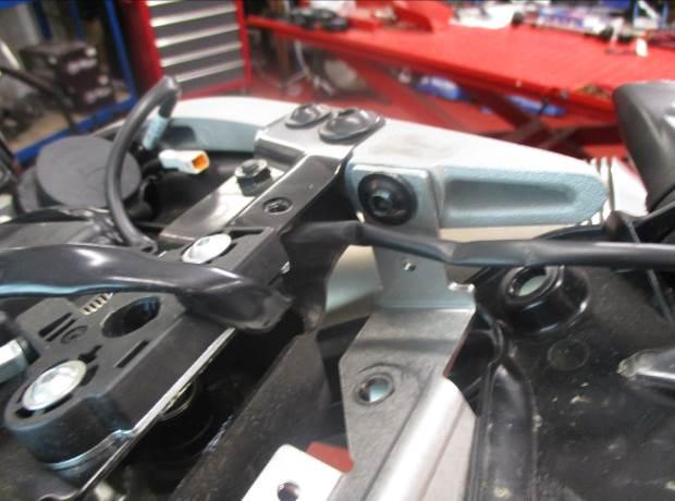
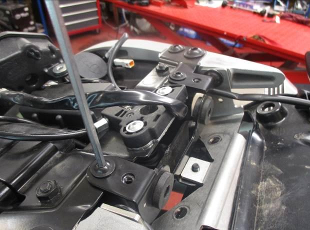
7 Page 7 of 19 Picture 23 Picture 24 Picture 25 Picture 26 FITTING INSTRUCTIONS Remove the seat. Undo the T40 Torx bolt which secures the RH exhaust to the exhaust mount (shown in Picture 1), and carefully pull the exhaust silencer out of the exhaust pipe. Repeat the previous step on the LH exhaust. Remove the two bolts securing the brake light assembly (shown in Picture 2), and carefully pull the brake light assembly rearwards to remove it from the mounting plate. The brake light mounting plate can now be removed, by undoing the three bolts shown in Picture 3. Undo the two bolts securing the exhaust mount (Picture 4) and remove the mount. Remove the two lower bolts securing the upper rear body panel (shown in Picture 5), ensuring that the spacers are put to one side ready for re-installation later. Remove the two upper bolts (shown in Picture 6) securing the upper rear body panel, and carefully remove the panel (shown in Picture 7). Remove the four bolts shown in Picture 8 and be sure to support the plastic undertray to prevent damaging the indicator wires.
8 Page 8 of 19 Trace the licence plate illuminator wire back to its connector and unplug it (shown in Picture 9 and Picture 10). Remove the two bolts securing the licence plate subframe (Picture 11) and ensure that it is being supported. Then carefully remove the subframe from the bike, taking care not to pull or damage any wires. Cut the 200mm long self-adhesive foam into two 100mm long strips and stick them to the top of the tail tidy (Picture 12). Feed the tail tidy through the plastic undertray (as shown in Picture 13) and using the original bolts, secure the tail tidy in place (Picture 14). Re-fit the brake light mounting plate, ensuring that the bottom tab is tucked underneath the tail tidy (Picture 15). NOTE THE TAIL TIDY MAY NEED TO BE ANGLED SLIGHLY IN ORDER TO RE-FIT THE MOUNT PLATE. Secure the brake light mounting plate back in place by using the three original bolts, with the bottom bolt tightened from underneath (Picture 16). Using the two M8 x 30mm button head bolts provided (ITEM 2), along with washers (ITEM 3) and Nyloc nuts (ITEM 4), secure the exhaust mounting plate to the tail tidy. Mount the licence plate illuminator assembly (ITEM 5) to the tail tidy (ITEM 1), using the bolts, nuts and washers provided, please note you will have to fit the light shroud and use a small amount of adhesive to hold it in position. Fit the provided length of heat shrink (ITEM 7) to protect the licence plate illuminator wires. Re-route the licence plate illuminator wiring, following the original wiring layout, using the supplied cable tie (ITEM 9) to neatly route the wires. Connect the licence plate illuminator connector (ITEM 6) to the wiring loom (Picture 19) and connect the two bullet connectors to the licence plate illuminator. Check operation of all lights at this stage (if illumination fails, swap the bullet connectors around). If fitting mini indicators (Ignore this section if using OEM Indicators) Trace the original indicator wires back to the connectors, and disconnect them, noting which is the LH and RH. Carefully remove the original indicators (noting the routing of the wiring), by gently pulling them out of the plastic undertray. Place two indicator adaptor inserts (ITEM 13), either side of the original indicator mount opening and feed the mini indicator wires through the two adaptors. Secure the mini indicator in place using the M8 nut provided with the mini indicator kit (shown in Picture 21). Connect the two indicator connectors (ITEM 12) to the original loom and connect the two bullet connectors to the mini indicators. Check operation of all lights at this stage (if illumination fails, swap the bullet connectors around). NOTE: 1 x set of RGR0001 resistors (available separately) may be required to achieve the correct flash rate. Stick two Velcro pads to the upper rear body panel and plastic undertray, before re-fitting the upper rear body panel (Picture 22 and Picture 23). Re-fit the upper rear body panel, ensuring that the spacers are re-installed for the bottom two mounts (Picture 24 and Picture 25). Carefully re-fit the brake light assembly, and secure in place using the two original bolts. Refit the seat as original and licence plate (it may require drilling). Please check the operation of all lights before riding the motorcycle.
9 Page 9 of 19 IMPORTANT: IF FITTING A FULL-SIZE LICENCE PLATE AND PLACING IT FAR DOWN ON THE LICENCE PLATE HANGER, THERE IS A SMALL CHANCE OF THE LICENCE PLATE HITTING THE BACK WHEEL UNDER HEAVY LOAD AND OVER LARGE BUMPS IN THE ROAD. IT IS YOUR RESPONSIBILITY TO CHECK FOR THIS POSSIBILITY AND TAKE AVOIDING ACTION. FAILURE TO CHECK THIS COULD RESULT IN SERIOUS INJURY. Depending on local laws, attach enclosed reflector (item 8) in an appropriate location ISSUE 1 26/09/2018 (LF) CONSUMER NOTICE The catalogue description and any exhibition of samples are only broad indications of the Products and may make design changes which do not diminish their performance or visual appeal and supplying them in such state shall conform to the order. The Buyer acknowledges no representation or warranty (other than as to title) has been given or will apply to the Products other than those in s order or confirmation and the Buyer confirms it has chosen the Products as being of merchantable quality and suitable for its particular purposes. Where fits the Products or undertakes other services it shall exercise reasonable skill and care and rectify any fault free of charge unless the workmanship has been disturbed. The Buyer is responsible for ensuring that the warranty on the motorcycle is not affected by the fitting of the Products. On return of any defective Products shall at its option either supply a replacement or refund the purchase money but shall not be liable if the Products have been modified or used or maintained otherwise than in accordance with s or manufacturer s instructions and good engineering practice or if the defect arises from accident or neglect. Other than identified above and subject to not limiting its liability for causing death and personal injury, it shall not be liable for indirect or consequential loss and otherwise its liability shall be limited to the amounts paid by the Buyer for the Products or the fitting or service concerned. These terms do not affect the Buyer s statutory rights. RETURNS POLICY (NON-FAULTY GOODS) Returns must be pre-authorised (if not pre-authorised the return will be rejected). Goods may only be returned direct to us if they were purchased direct from us (customer must prove if necessary). Otherwise to be returned to original vendor. Goods must be in re-sellable condition, in the opinion of. All returns are subject to a 25% restocking and handling fee (25% of the gross value exc. P&P at the prevailing price at time of purchase). The customer must pay any and all carriage charges. No returns of discontinued products, unless within 14 days of purchase. This policy does not affect your statutory rights and does not refer to faulty goods.
10 Page 10 of 19 NOTICE DE MONTAGE POUR BK SUPPORT DE PLAQUE DUCATI SCRAMBLER Le kit contient les articles exposés ci-dessous, vérifier que toutes les pièces soient présentes avant de procéder au montage. La façon dont le kit est emballé ne correspond pas forcément à la façon de monter les pièces sur la moto. LES PARTIES PRESENTEES PEUVENT ETRE UNIQUEMENT REPRESENTATIVES (POUR LA CLARTÉ DES INSTRUCTIONS UNIQUEMENT). Notez que si les kits sont emballés avec des rondelles en caoutchouc servant à tenir les composants, ces rondelles doivent être jetées! Notice disponible au téléchargement sur
11 Page 11 of 19 LÉGENDE ARTICLE 1 = SUPPORT DE PLAQUE (TB0256). (x1) ARTICLE 2 = M8 x 30mm BOULON (x2) ARTICLE 3 = M8 RONDELLE (x2) ARTICLE 4 = M8 ÉCROU (x2) ARTICLE 5 = ASSEMBLAGE FEU DE PLAQUE (LA0002). (x1) ARTICLE 6 = CONNECTEUR DE FEU DE PLAQUE (CON0014) (x1) ARTICLE 7 = 180mm LONGEUR DE MANCHON THERMO RÉTRACTABLE (x1) ARTICLE 8 = RÉFLECTEUR (x1) ARTICLE 9 = COLLIERS DE SERRAGE (x1) ARTICLE 10 = MOUSSE AUTOCOLLANTE (x1) ARTICLE 11 = 20 x 20mm PADS EN VELCRO NOIR AUTOCOLLANT ARTICLE 12 = CONNECTEUR DE CLIGNOTANT (CON0015) (x2) ARTICLE 13 = INSERT D ADAPTATEUR DE CLIGNOTANT (I0033) (x4)
12 Page 12 of 19 OUTILS REQUIS Jeu complet de douilles / clés. Jeu de clés Allen Clé Torx T40 Un peu d adhésif VALEURS DE SERRAGE RECOMMANDÉES M4 BOULON = 8Nm M5 BOULON = 12Nm M6 BOULON = 15Nm M8 BOULON = 20Nm M10 BOULON = 40Nm NOTICE DE MONTAGE Enlever le siège. Enlever le boulon T40 Torx qui fixe l échappement droit au support d échappement (voir Photo 1), puis tirer le silencieux d échappement en dehors du pot. Répéter l étape précédente sur l échappement gauche. Enlever les 2 boulons qui fixent l assemblage de feu stop (voir Photo 2), puis tirer l ensemble de feu stop vers l arrière pour l enlever de la plaque de montage La plaque de montage du feu stop peut maintenant être enlevée, en enlevant les 3 boulons indiqués sur la Photo 3. Enlever les 2 boulons qui fixent le support d échappement (Photo 4) puis enlever le support. Enlever les 2 boulons inférieurs qui fixent le panneau de carénage supérieur arrière (voir Photo 5), en veillant à ce que les entretoises soient mises de côté pour être réinstallées plus tard. Enlever les 2 boulons supérieurs (voir Photo 6) qui fixent le panneau de carénage arrière, puis enlever le panneau (voir Photo 7). Enlever les 4 boulons indiqués sur la Photo 8 puis supportez le sous plateau pour éviter d abimer les fils de clignotant. Tracer le fil de feu de plaque jusqu à son connecteur puis débranchez le (voir Photo 9 et Photo 10). Enlever les 2 boulons qui fixent le sous cadre de plaque (Photo 11) en faisant attention à le supporter. Ensuite, enlever le sous-cadre de la moto, en faisant attention à ne pas tirer sur les fils ni à les abîmer. Couper la mousse autocollante de 200mm en 2 pièces de 100mm puis collez les sur le haut du support de plaque (Photo 12). Passer le support de plaque dans le sous plateau en plastique (voir Photo 13) puis fixer le support de plaque à l aide des boulons d origine (Photo 14).
13 Page 13 of 19 Remonter la plaque de montage du feu stop, en veillant à ce que l onglet du bas soit rangé sous le support de plaque (Photo 15). NOTE LE SUPPORT DE PLAQUE DOIT ÊTRE LÉGÈREMENT INCLINÉ POUR QUE VOUS PUISSIEZ Y RÉINSTALLER LA PLAQUE DE SUPPORT. Fixer la plaque de montage de feu stop en place, en utilisant les 3 boulons d origine, avec le boulon du bas serré pas dessous (Photo 16). Utiliser les 2 boulons M8 x 30mm fournis (ARTICLE 2), avec des rondelles (ARTICLE 3) et écrous (ARTICLE 4), fixer la plaque de montage de l échappement sur le support de plaque. Monter l assemblage de feu de plaque (ARTICLE 5) sur le support de plaque (ARTICLE 1), en utilisant les boulons, écrous et rondelles fournis, notez que vous devrez monter le linceul de feu et utiliser un peu d adhésif pour fixer la position. Appliquer le manchon thermos rétractable (ARTICLE 7) sur le fils du feu de plaque afin de les protéger. Route à nouveau les fils de feu de plaque, en suivant le schéma du câblage d origine, et en utilisant le collier de serrage fourni (ARTICLE 9) pour router les fils. Connecter le connecteur de feu de plaque (ARTICLE 6) sur le faisceau de fils (Photo 19) puis connecter les 2 connecteurs au feu de plaque. Vérifiez que tous les feux fonctionnent à ce stade (Si l éclairage échoue, tournez les connecteurs). Si vous montez les mini clignotants (Ignorer cette partie si vous réinstallez les clignotants d origine) Tracer les fils de clignotant d origine jusqu aux connecteurs, puis déconnectez les en notant chaque côté gauche et droit. Enlever délicatement les clignotants d origine (en notant le routage du fil), en les tirant du sous plateau en plastique. Placer 2 inserts d adaptateur de clignotant (ARTICLE 13), de chaque côté du support de clignotant d origine en ouvrant et en passant les fils dans les 2 adaptateurs. Fixer le mini clignotant en place en utilisant l écrou M8 founi avec le kit de mini clignotant (voir Photo 21). Connecter les 2 connecteurs de clignotant (ARTICLE 12) sur le faisceau d origine puis connecter les 2 connecteurs sur les mini clignotants. Vérifiez que tous les feux fonctionnent à ce stade (Si l éclairage échoue, tournez les connecteurs). NOTE : 1 x set de résistances RGR0001 (disponible séparément) peuvent être nécessaires pour obtenir le bon niveau d éclairage. Coller 2 Velcro sur le panneau de carénage arrière supérieur et le sous plateau, avant de remonter le panneau de carénage arrière supérieur (Photo 22 et Photo 23). Remonter le panneau de carénage arrière supérieur, en veillant à ce que les entretoises soient réinstallées sur les 2 supports du bas (Photo 24 et Photo 25). Remonter l assemblage de feu stop puis fixez le en place en utilisant les 2 boulons d origine. Remonter le siège comme à l origine ainsi que la plaque d immatriculation, peut nécessiter un perçage. Tester l ensemble des feux avant de prendre la route. IMPORTANT : Si vous installez une grosse plaque, il y a un risque que la plaque entre en contact avec la roue arrière en cas de choc sur la route (bosse, grosse charge etc..). Il est de votre responsabilité de vérifier que cela ne puisse pas se produire. Ne pas effectuer ces vérifications peut entrainer des dommages ainsi que des blessures graves pour le pilote. Selon les lois locales, attacher le réflecteur rouge (article 8) à l endroit approprié. ISSUE 1 26/09/2018 (LF)
14 Page 14 of 19 CONSUMER NOTICE The catalogue description and any exhibition of samples are only broad indications of the Products and may make design changes which do not diminish their performance or visual appeal and supplying them in such state shall conform to the order. The Buyer acknowledges no representation or warranty (other than as to title) has been given or will apply to the Products other than those in s order or confirmation and the Buyer confirms it has chosen the Products as being of merchantable quality and suitable for its particular purposes. Where fits the Products or undertakes other services it shall exercise reasonable skill and care and rectify any fault free of charge unless the workmanship has been disturbed. The Buyer is responsible for ensuring that the warranty on the motorcycle is not affected by the fitting of the Products. On return of any defective Products shall at its option either supply a replacement or refund the purchase money but shall not be liable if the Products have been modified or used or maintained otherwise than in accordance with s or manufacturer s instructions and good engineering practice or if the defect arises from accident or neglect. Other than identified above and subject to not limiting its liability for causing death and personal injury, it shall not be liable for indirect or consequential loss and otherwise its liability shall be limited to the amounts paid by the Buyer for the Products or the fitting or service concerned. These terms do not affect the Buyer s statutory rights. RETURNS POLICY (NON-FAULTY GOODS) Returns must be pre-authorised (if not pre-authorised the return will be rejected). Goods may only be returned direct to us if they were purchased direct from us (customer must prove if necessary). Otherwise to be returned to original vendor. Goods must be in re-sellable condition, in the opinion of. All returns are subject to a 25% restocking and handling fee (25% of the gross value exc. P&P at the prevailing price at time of purchase). The customer must pay any and all carriage charges. No returns of discontinued products, unless within 14 days of purchase. This policy does not affect your statutory rights and does not refer to faulty goods.
15 Page 15 of 19 MONTAGEANLEITUNG FÜR BK KENNZEICHENHALTER DUCATI SCRAMBLER ALLE KIT-TEILE SIND UNTEN ABGEBILDET UND GEKENNZEICHNET. BEVOR SIE MIT DER MONTAGE BEGINNEN, ÜBERPRÜFEN SIE, DASS ALLE TEILE VORHANDEN SIND. Hinweis: Die Verpackung der Teile stellt nicht die Reihenfolge der Montage dar. DIE UNTEN ABGEBILDETEN TEILE DIENEN LEDIGLICH ZUR ERKLÄRUNG Hinweis für Kits mit Plastikunterlegscheiben an den Schrauben Diese Plastikunterlegscheiben werden nicht für den Einbau benötigt! Eine digitale Version dieser Montageanleitung kann auf folgender Seite heruntergeladen werden:
16 Page 16 of 19 LIEFERUMFANG ARTIKEL 1 = KENNZEICHENHALTER (TB0256) (x1) ARTIKEL 2 = M8 x 30mm INBUSSCHRAUBE (x2) ARTIKEL 3 = M8 UNTERLEGSCHEIBE (x2) ARTIKEL 4 = M8 SELBSTSICHERNDE MUTTER (x2) ARTIKEL 5 = KENNZEICHENBELEUCHTUNG (LA0002) (x1) ARTIKEL 6 = VERBINDUNG FÜR DIE KENNZEICHENBELEUCHTUNG (CON0014) (x1) ARTIKEL 7 = 180mm SCHRUMPFSCHLAUCH (x1) ARTIKEL 8 = RÜCKSTRAHLER (x1) ARTIKEL 9 = KLEINE KABELBINDER (x1) ARTIKEL 10 = SELBSTKLEBENDER SCHAUMSTOFF (SCHWARZ) (x1) ARTIKEL 11 = 20 x 20mm SELBSTKLEBENDE SCHWARZE KLETTBAND-PADS ARTIKEL 12 = VERBINDUNG FÜR DIE BLINKER (CON0015) (x2) ARTIKEL 13 = ADAPTER-EINSATZ FÜR DIE BLINKER (I0033) (x4)
17 Page 17 of 19 SIE BENÖTIGEN FOLGENDES WERKZEUG Steckschlüsselsatz Satz Inbusschlüssel T40 Torx-Einsatz etwas Sekundenkleber MAX. ANZUGSDREHMOMENTE: M4 SCHRAUBE = 8 NM M5 SCHRAUBE = 12NM M6 SCHRAUBE = 15NM M8 SCHRAUBE = 20NM M10 SCHRAUBE = 40NM MONTAGEANLEITUNG Entfernen Sie den Sitz. Lösen Sie die T40 Torx-Schraube, die den rechten Auspuff an der Auspuffhalterung befestigt (siehe Abbildung 1), und ziehen Sie den Schalldämpfer vom Auspuffrohr. Wiederholen Sie diesen Schritt mit dem linken Auspuff. Entfernen Sie die zwei Schrauben, die die Bremslicht-Einheit befestigen (siehe Abbildung 2), und ziehen Sie die Einheit nach hinten, um sie von der Montageplatte zu entfernen. Die Montageplatte für das Bremslicht kann jetzt entfernt werden, indem Sie die drei Schrauben, die in Abbildung 3 abgebildet sind, lösen. Lösen Sie die zwei Schrauben, die die Auspuffhalterung befestigen (Abbildung 4) und entfernen Sie die Halterung. Entfernen Sie die zwei unteren Schrauben, die die obere Heckverkleidung (siehe Abbildung 5) befestigen bitte darauf achten, dass beide Distanzhalter zur Seite gelegt werden, diese werden für den späteren Einbau benötigt. Entfernen Sie die zwei oberen Schrauben (siehe Abbildung 6), die die obere Heckverkleidung befestigen, und entfernen Sie die Verkleidung (siehe Abbildung 7). Entfernen Sie die vier Schrauben, die in Abbildung 8 abgebildet sind stützen Sie dabei die untere Abdeckung, um zu verhindern, dass die Kabel für die Blinker beschädigt werden. Trennen Sie den Stecker für die Kennzeichenbeleuchtung (siehe Abbildungen 9 und 10). Entfernen Sie die zwei Schrauben, die den Hilfsrahmen für den Kennzeichenhalter befestigen (Abbildung 11) den Hilfsrahmen dabei stützen. Entfernen Sie den Hilfsrahmen vom Motorrad bitte darauf achten, dass die Kabel nicht beschädigt oder gezogen werden. Den 200mm selbstklebenden-schaumstoff in zwei 100mm lange Streifen schneiden, und kleben Sie sie oben auf dem Kennzeichenhalter (Abbildung 12). Führen Sie den Kennzeichenhalter durch die untere Abdeckung (wie in Abbildung 13 abgebildet), und den Kennzeichenhalter mit den Originalschrauben in Position befestigen (Abbildung 14).
18 Page 18 of 19 Montieren Sie die Montageplatte für das Bremslicht wieder bitte darauf achten, dass die untere Lasche unter dem Kennzeichenhalter verstaut ist (Abbildung 15). HINWEIS DER KENNZEICHENHALTER MUSS EVENTUELL ETWAS SCHRÄG ANGEWINKELT WERDEN, UM DIE MONTAGEPLATTE WIEDER ANBAUEN ZU KÖNNEN. Sichern Sie die Montageplatte für das Rücklicht wieder in Position mit den drei Originalschrauben die untere Schraube wird von unten festgezogen (Abbildung 16). Benutzen Sie die zwei M8 x 30mm Inbusschrauben vom Kit (Artikel 2), sowie die Unterlegscheiben (Artikel 3) und selbstsichernde Muttern (Artikel 4), um die Auspuff-Montageplatte am Kennzeichenhalter zu befestigen. Die Kennzeichenbeleuchtung-Einheit (Artikel 5) am Kennzeichenhalter (Artikel 1) befestigen mit den Schrauben, Muttern und Unterlegscheiben vom Kit. Hinweis: etwas Sekundenkleber wird benötigt, um die Lichtabdeckung in Position zu befestigen. Den Schrumpfschlauch vom Kit (Artikel 7) anbringen, um die Kabel für die Kennzeichenbeleuchtung zu schützen. Die Verkabelung der Kennzeichenbeleuchtung neu verlegen, unter Berücksichtigung der original Verlegung die mitgelieferten Kabelbinder (Artikel 9) verwenden, um die Kabel ordentlich zu verstauen. Verbinden Sie den Verbinder für die Kennzeichenbeleuchtung (Artikel 6) mit dem Kabelbaum (Abbildung 19) und verbinden Sie die zwei Kabelverbinder mit der Kennzeichenbeleuchtung. Überprüfen Sie nun die Funktion der Beleuchtung (Falls die Beleuchtung nicht funktionieren sollte, tauschen Sie die Kabelverbinder untereinander). Wenn Sie Miniblinker verwenden: (Diese Schritte überspringen, wenn Sie die original Blinker verwenden) Trennen Sie die Verbinder für die original Blinkerkabel bitte die entsprechende Seite (rechts/links) notieren. Entfernen Sie die original Blinker (die Verlegung der Kabel notieren), indem Sie sie vorsichtig aus der unteren Abdeckung ziehen. Die zwei Adapter-Einsätze für die Blinker (Artikel 13) an beiden Seiten der original Öffnung für die Blinkerhalterung anbringen und die Kabel für die Miniblinker durch die zwei Adapter führen. Die Miniblinker in Position befestigen mit der M8 Mutter, die im Miniblinker-Kit enthalten ist (siehe Abbildung 21). Verbinden Sie die zwei Verbindungen für die Blinker (Artikel 12) mit dem original Kabelbaum und verbinden Sie die zwei Kabelverbinder mit den Miniblinkern. Überprüfen Sie nun die Funktion der Beleuchtung (Falls die Beleuchtung nicht funktionieren sollte, tauschen Sie die Kabelverbinder untereinander). HINWEIS: 1 x Satz RGR0001 Widerstände (separat erhältlich) wird eventuell benötigt, um die richtige Blitzgeschwindigkeit zu bekommen. Kleben Sie die zwei Klettband-Pads an der oberen Heckverkleidung und der unteren Abdeckung, bevor Sie die obere Heckverkleidung wieder montieren (siehe Abbildungen 22 und 23). Montieren Sie die untere Heckverkleidung wieder bitte darauf achten, dass die Distanzhalter wieder an den zwei unteren Halterungen montiert werden (Abbildung 24 und Abbildung 25). Montieren Sie die Bremslicht-Einheit wieder und mit befestigen Sie sie mit den zwei original Schrauben. Montieren Sie den Sitz wie ursprünglich wieder sowie das amtliche Kennzeichen (Bohrungen im Kennzeichen evtl. notwendig). Überprüfen Sie die Funktion der kompletten Beleuchtung (Blinker und Kennzeichenhalterbeleuchtung) nochmal vor Gebrauch des Fahrzeuges.
19 Page 19 of 19 WICHTIG: WENN EIN GROSSES KENNZEICHEN ZU WEIT NACH UNTEN MONTIERT WIRD, BESTEHT BEI SCHWEREM LAST ODER DURCH GROSSE BODENWELLEN EIN GERINGES RISIKO, DASS DAS KENNZEICHEN AN DAS HINTERRAD STOSSEN KANN. ES LIEGT IN IHRER VERANTWORTUNG DIES ZU ÜBERPRÜFEN UND, WENN NOTWENDIG, VORZUBEUGENDE MASSNAHMEN ZU ERGREIFEN. DIE NICHTBEACHTUNG DIESES SICHERHEITSHINWEIS KANN ZU SCHWEREN VERLETZUNGEN FÜHREN. Entsprechend der gesetzlichen Vorschriften, den mitgelieferten Rückstrahler (Artikel 8) anbringen. AUSGABE 1 26/09/2018 (LF) CONSUMER NOTICE The catalogue description and any exhibition of samples are only broad indications of the Products and may make design changes which do not diminish their performance or visual appeal and supplying them in such state shall conform to the order. The Buyer acknowledges no representation or warranty (other than as to title) has been given or will apply to the Products other than those in s order or confirmation and the Buyer confirms it has chosen the Products as being of merchantable quality and suitable for its particular purposes. Where fits the Products or undertakes other services it shall exercise reasonable skill and care and rectify any fault free of charge unless the workmanship has been disturbed. The Buyer is responsible for ensuring that the warranty on the motorcycle is not affected by the fitting of the Products. On return of any defective Products shall at its option either supply a replacement or refund the purchase money but shall not be liable if the Products have been modified or used or maintained otherwise than in accordance with s or manufacturer s instructions and good engineering practice or if the defect arises from accident or neglect. Other than identified above and subject to not limiting its liability for causing death and personal injury, it shall not be liable for indirect or consequential loss and otherwise its liability shall be limited to the amounts paid by the Buyer for the Products or the fitting or service concerned. These terms do not affect the Buyer s statutory rights. RETURNS POLICY (NON-FAULTY GOODS) Returns must be pre-authorised (if not pre-authorised the return will be rejected). Goods may only be returned direct to us if they were purchased direct from us (customer must prove if necessary). Otherwise to be returned to original vendor. Goods must be in re-sellable condition, in the opinion of. All returns are subject to a 25% restocking and handling fee (25% of the gross value exc. P&P at the prevailing price at time of purchase). The customer must pay any and all carriage charges. No returns of discontinued products, unless within 14 days of purchase. This policy does not affect your statutory rights and does not refer to faulty goods.
Fitting Instructions for RAD0171BK Radiator Guard YAMAHA MT
 Fitting Instructions for RAD0171BK Radiator Guard YAMAHA MT-07 2014- In This Kit There Should Be 1x Radiator Guard (RAD0171BK). 4x M6 Nyloc Nuts. 4x M6 Washers. 2x 100mm Lengths of self-adhesive Foam.
FITTING INSTRUCTIONS FOR BLP0032SI REAR FOOTREST BLANKING PLATES YAMAHA MT
 FITTING INSTRUCTIONS FOR BLP0032SI REAR FOOTREST BLANKING PLATES YAMAHA MT-07 2014- Please note that the way the kit is packed does not necessarily represent the way of mounting to the bike THE PARTS SHOWN
Fitting Instructions for RAD0141BK Radiator Guard KAWASAKI ZX-6R
 Fitting Instructions for RAD0141BK Radiator Guard KAWASAKI ZX-6R 636 2013 In This Kit There Should Be 1 x Radiator Guard (RAD0141BK) 2 x 100mm Lengths of self-adhesive Foam. 4 x 4mm Cable Ties x 220mm
Fitting Instructions for OCG0014BK Oil Cooler Guard Ducati Monster 1100 / 1100S / 1100EVO & 795/796 '09-
 Fitting Instructions for OCG0014BK Oil Cooler Guard Ducati Monster 1100 / 1100S / 1100EVO & 795/796 '09- In This Kit There Should Be 1x Oil Cooler Guard (OCG0014) 1x M6 x 25mm Long Button Head Bolt 1x
FITTING INSTRUCTIONS FOR CP0404BL/WH NO-CUT AERO CRASH PROTECTORS HUSQVARNA 701 ENDURO/SUPERMOTO 2016-
 FITTING INSTRUCTIONS FOR BL/WH NO-CUT AERO CRASH PROTECTORS HUSQVARNA 701 ENDURO/SUPERMOTO 2016- Page 1 PICTURE A PICTURE B REAR OF BIKE FRONT OF BIKE PICTURE C THIS KIT CONTAINS THE ITEMS PICTURED AND
Fitting Instructions for SRG0034 Radiator Guard Radiator Guard KAWASAKI VERSYS
 Fitting Instructions for SRG0034 Radiator Guard Radiator Guard KAWASAKI VERSYS 650 2015- In This Kit There Should Be 1x Radiator Guard. 1x Spacer. 1 x M6 Bolt. 1x M6 Nut and Washer. 6 x Cable/Zip Ties.
FITTING INSTRUCTIONS FOR PKS0057SI KICKSTAND SHOE MV Augusta F
 FITTING INSTRUCTIONS FOR PKS0057SI KICKSTAND SHOE MV Augusta F4 1000 04- Please note that the way the kit is packed does not necessarily represent the way of mounting to the bike. THE PARTS SHOWN MAY BE
Fitting Instructions for RAD0164 BK/OR Radiator Guard KTM 390 DUKE 2013
 Fitting Instructions for RAD0164 BK/OR Radiator Guard KTM 390 DUKE 2013 In This Kit There Should Be 1x Radiator Guard (RAD0164BK/OR) 4 x Cable/Zip Tie 2x 100mm Lengths of self adhesive Foam To fit the
FITTING INSTRUCTIONS FOR CP0393BL AERO CRASH PROTECTORS SUZUKI GSX-S
 Page1 FITTING INSTRUCTIONS FOR BL AERO CRASH PROTECTORS SUZUKI GSX-S 1000 2015- PICTURE A PICTURE B REAR OF BIKE FRONT OF BIKE PICTURE C THIS KIT CONTAINS THE ITEMS PICTURED AND LABELLED BELOW. DO NOT
FITTING INSTRUCTIONS FOR LP0249BK LICENCE PLATE BRACKET
 FITTING INSTRUCTIONS FOR BK LICENCE PLATE BRACKET Tail Tidy for Ducati Monster 821 '18-, 1200 (S) '17- & 1200R '18- for Ducati Monster 821 (2018) Page 1 THIS KIT CONTAINS THE ITEMS PICTURED AND LABELLED
FITTING INSTRUCTIONS FOR LP0139BK LICENCE PLATE BRACKET HONDA CBR600RR 2013-
 FITTING INSTRUCTIONS FOR LP0139BK LICENCE PLATE BRACKET HONDA CBR600RR 2013- THIS KIT CONTAINS THE ITEMS PICTURED AND LABELLED BELOW. DO NOT PROCEED UNTIL YOU ARE SURE ALL PARTS ARE PRESENT. Please note
Fitting Instructions for DG0016BK DOWNPIPE GRILLE HONDA CBR600RR 2013
 Fitting Instructions for DG0016BK DOWNPIPE GRILLE HONDA CBR600RR 2013 In This Kit There Should Be 1x Downpipe Grille (DG0016BK) Picture 1 Picture 2 Picture 3 Picture 4 Picture 5 Picture 6 TOOLS REQUIRED
In this kit there should be: 1 x Engine Case Cover (ECC0085) 2 x M6x28mm long button head bolts PLEASE READ THESE INSTRUCTIONS FULLY BEFORE STARTING
 2 x M6x28mm long button head bolts PLEASE READ THESE INSTRUCTIONS FULLY BEFORE STARTING") FITTING INSTRUCTIONS FOR ECC0085 LHS WATER PUMP COVER TO FIT ALL WATER COOLED DUCATI S REMOVE REMOVE In this kit there should be: 1 x Engine Case Cover (ECC0085) 2 x M6x28mm long button head bolts PLEASE
FITTING INSTRUCTIONS FOR ECC0085 LHS WATER PUMP COVER TO FIT ALL WATER COOLED DUCATI S REMOVE REMOVE In this kit there should be: 1 x Engine Case Cover (ECC0085) 2 x M6x28mm long button head bolts PLEASE
FITTING INSTRUCTIONS FOR LP0151BK LICENCE PLATE BRACKET HONDA CBR500R/ CB500X and CB500F 2013
 FITTING INSTRUCTIONS FOR LP0151BK LICENCE PLATE BRACKET HONDA CBR500R/ CB500X and CB500F 2013 Page 1 THIS KIT CONTAINS THE ITEMS PICTURED AND LABELLED BELOW. DO NOT PROCEED UNTIL YOU ARE SURE ALL PARTS
Fitting Instructions for RSET14BK Adjustable Rearsets Aprilia RSV4R and Factory ( 09-)
") Fitting Instructions for RSET4BK Adjustable Rearsets Aprilia RSV4R and Factory ( 09-) First remove the original Aprilia rearsests. Install on the gear shaft connector () onto the gear shaft. Then connect
Fitting Instructions for RSET4BK Adjustable Rearsets Aprilia RSV4R and Factory ( 09-) First remove the original Aprilia rearsests. Install on the gear shaft connector () onto the gear shaft. Then connect
FITTING INSTRUCTIONS FOR RSET12BK ADJUSTABLE REARSETS FOR TRIUMPH DAYTONA 675 ( )
") FITTING INSTRUCTIONS FOR RSET12BK ADJUSTABLE REARSETS FOR TRIUMPH DAYTONA 675 (2008-2011) First remove the original Triumph rearsests. Then remove the engine axle and insert it from the otherside (from
FITTING INSTRUCTIONS FOR RSET12BK ADJUSTABLE REARSETS FOR TRIUMPH DAYTONA 675 (2008-2011) First remove the original Triumph rearsests. Then remove the engine axle and insert it from the otherside (from
FITTING INSTRUCTIONS FOR RGH0002BK REAR WHEEL HUGGER YAMAHA FZ8
 FITTING INSTRUCTIONS FOR RGH0002BK REAR WHEEL HUGGER YAMAHA FZ8 THIS KIT CONTAINS THE ITEMS PICTURED AND LABELLED BELOW. DO NOT PROCEED UNTIL YOU ARE SURE ALL PARTS ARE PRESENT. Please note that the way
PICTURE C Please note that the way the kit is packed does not necessarily represent the way of mounting to the bike
 FITTING INSTRUCTIONS FOR BL NO CUT CRASH PROTECTORS BMW S1000R 2014 Page 1 TOWARDS REAR OF BIKE TOWARDS FRONT OF BIKE PICTURE C Please note that the way the kit is packed does not necessarily represent
FITTING INSTRUCTIONS FOR CP0368BL AERO CRASH PROTECTORS DUCATI MONSTER & MONSTER
 Page1 FITTING INSTRUCTIONS FOR BL AERO CRASH PROTECTORS DUCATI MONSTER 1200 14- & MONSTER 821 14- Picture A Picture B THIS KIT CONTAINS THE ITEMS PICTURED AND LABELLED BELOW. DO NOT PROCEED UNTIL YOU ARE
60AZinkenverstellgeräte. 60A Ajusteurs de Fourches
 Parts Manual Ersatzteilliste Manuel de pièces détachées c 60A Fork Positioners 60AZinkenverstellgeräte 60A Ajusteurs de Fourches Last revision: 24/03/2011 cascade Parts Manual - 60A82017 35D Fork Positioner
Werkstattmobil Workshop trolley Poste mobile d atelier
 Technical Furniture Werkstattmobil Workshop trolley Poste mobile d atelier Assembly Instructions Bitte beachten Sie Please read A consulter imperativement Weitere Dokumentation beachten Refer to the other
VWR FOR SIEVING. Test sieve shakers and accessories. Ultrasonic sieving systems. Sample splitters. Test sieves. Standards.
 VWR FOR SIEVING Test sieve shakers and accessories Ultrasonic sieving systems Sample splitters Test sieves Standards Ultrasonic baths Useful accessories Available from P:0800 34 24 66 www.bio-strategy.com
READ AND FOLLOW ALL SAFETY INSTRUCTIONS 1. DANGER RISK OF SHOCK DISCONNECT POWER BEFORE INSTALLATION
 UR Series LED Upgrade Kit Includes: 24" Linear Option IMPORTANT SAFEGUARDS When using electrical equipment, basic safety precautions should always be followed including the following: READ AND FOLLOW ALL
INSTALLATION INSTRUCTIONS LED RETROFIT ASSEMBLY (LRA) Rev F
 Rev F") SAFETY S IMPORTANT SAFETY INFORMATION SUITABLE FOR DRY OR DAMP LOCATIONS. NOT FOR USE WITH PHASE CUT DIMMERS. Risk of shock. Disconnect power before installation. DANGER CONVIENT AUX EMPLACEMENTS HUMIDES.
SAFETY S IMPORTANT SAFETY INFORMATION SUITABLE FOR DRY OR DAMP LOCATIONS. NOT FOR USE WITH PHASE CUT DIMMERS. Risk of shock. Disconnect power before installation. DANGER CONVIENT AUX EMPLACEMENTS HUMIDES.
VersaWall SlimLine 1750
 Index Stick built curtain wall 1 3/4"(44.5mm) profile Mur rideau avec profilé de 1 3/4"(44.5mm) Capped Couvercles à enclenchement Primary components - back sections Composantes principales - traverses
MOONRING 1.5 MOONRING 3
 INSTALLATION INSTRUCTIONS MOONRING 1.5 MOONRING 3 MR1.5 & MR3 Suspended, Ceiling LED n A 1035 22nd Avenue, Unit 1 Oakland, CA 94606 P 510.489.2530 E TalkToUs@alwusa.com W alwusa.com Safety & Warnings!
INSTALLATION INSTRUCTIONS MOONRING 1 LP1/MR1
 INSTALLATION INSTRUCTIONS MOONRING 1 LP1/MR1 Suspended, Ceiling LED n A 1035 22nd Avenue, Unit 1 Oakland, CA 94606 P 510.489.2530 E TalkToUs@alwusa.com W alwusa.com Safety & Warnings! 1. Read all instructions.
Specification Grade Contemporary Wall Mount/Technical Installation Data
 AVAILABLE CONFIGURATIONS RECESSED MOUNT SURFACE MOUNT MOUNTING REQUIREMENTS A. Recessed Mount: Minimum 4-Gang Box, 1-5/8 in. Deep (72.8 Cubic Inches) with 4-Gang Box Cover (20.3 Cubic Inches) B. Surface
INSTRUCTION MANUAL - GUIDE D INSTALLATION H101 SHOWER / DOUCHE 12 / 2017 TUB / BAIGNOIRE
 INSTRUCTION MANUAL - GUIDE D INSTALLATION H101 SHOWER / DOUCHE 12 / 2017 TUB / BAIGNOIRE Please keep this manual and product code number for future reference and for ordering replacement parts if necessary.
Installation Guidelines
 Installation Guidelines 5000-10-0338-MAN CF Moto VERSION A WARNING Please read carefully each part of this document as well as the User Manual prior to assembling, installing and using the Track System.
UB-2 2 Universal Button
 UB-2 2 Universal Button UB-2/LTUL Universal Button with Latching Timer ADA Compliant For UB-2/LTUL the enclosed timer is to be used and installed per the enclosed LT-1UL installation sheet. For access
INSTALLATION INSTRUCTIONS LIGHTPLANE 3.5. LP3.5 Suspended LED. A nd Avenue, Unit 1. CA P E W alwusa.
 Oakland, INSTALLATION INSTRUCTIONS LIGHTPLANE 3.5 LP3.5 Suspended LED A 1035 22nd Avenue, Unit 1 n CA 94606 P 510.489.2530 E TalkToUs@alwusa.com W alwusa.com Safety & Warnings! 1. Read all instructions.
WARNING AVERTISSEMENT
 Installation Guidelines Directives d installation 5000-05-0125-MAN Polaris WARNING Possibility of incompatibility between differential ratios. Before installation on this vehicle, it is *MANDATORY* to
Assembly & operating VIDEOS online at: Les VIDÉOS d assemblage et d opération en ligne au:
 Assembly & operating VIDEOS online at: Les VIDÉOS d assemblage et d opération en ligne au: http://murphycube.com 1A Parts List Liste des piéces Wood Block Block Slats Lattes x 3 Arm (Left Hand) Bras (côté
INSTALLATION INSTRUCTIONS
 INDIGO-CLEAN TECHNOLOGY RETROFIT KIT INSTALLATION INSTRUCTIONS 1 IMPORTANT SAFETY INFORMATION Risk of shock. Disconnect power before installation. DANGER- RISQUE DE CHOC- COUPER L ALIMENTATION AVANT L
Parent s Guide. This guide contains important information. Please keep it for future reference US
 Parent s Guide This guide contains important information. Please keep it for future reference. 91-003324-000 US INTRODUCTION The Stack & Tumble Elephant TM provides a silly twist on the classic ring stacker.
ZAZERI 48" ZAZERI 60"
 Installation alcôve A et installation en coin B Built-in A and corner B installation ZAZERI " ZAZERI 60" ZITTACLEAN " (5 / "~6 /6") (5mm~77mm) 60" (57 7/6"~5 5/" ) (59mm~9mm) "(9 /"~0 /") (75mm~77mm )
MRAD Universal Measuring Arm System For Optical/Magnetic and Fiber Optic Encoders
 Measuring Wheel Meauring Arm Encoder (Absolute or Incremetnal) Spring-loaded, adjustable measuring arm for universal applications Measuring wheels are utilized in combination with encoders to measure material
SCHUTZLEISTEN FÜR STOSSFÄNGER PROTECTIONS PARE-CHOCS KIT CONTENT - STÜCKLISTE - CONTENU - KIT - INHOUD REAR LHS
 TOYOTA HB & DOOR PARTNUMBER : BUMPER PROTECTORS SCHUTZLEISTEN FÜR STOSSFÄNGER PROTECTIONS PARE-CHOCS BUMPER BESCHERMER KIT CONTENT - STÜCKLISTE - CONTENU - KIT - INHOUD PZ1-E0-01 PZ1-E0-0 PZ1-E0-0 FRONT
INSTALLATION INSTRUCTIONS SUPERPLANE 2.5. Suspended. A nd Avenue, Unit 1 Oakland, CA P E W alwusa.
 INSTALLATION INSTRUCTIONS SUPERPLANE 2.5 Suspended A 1035 22nd Avenue, Unit 1 Oakland, CA 94606 P 510.489.2530 E TalkToUs@alwusa.com W alwusa.com SP2.5S - Safety & Warnings! 1. Read all instructions. 2.
Captivate Illuminated Mirror Light
 ENGLISH WARNINGS & SAFETY INFORMATION: PLEASE READ CAREFULLY FRANÇAIS MISES EN GARDE ET SÉCURITÉ: SE IL VOUS PLAÎT LIRE ATTENTIVEMENT WARNING: RISK OF FIRE OR ELECTRIC SHOCK. LUMINAIRE WIRING AND ELECTRICAL
INSTALLATION INSTRUCTIONS LED Canopy Retrofit Kit
 INSTALLATION INSTRUCTIONS LED Canopy Retrofit Kit TRMUNV065ECxyyZ TRAUNV065ECxyyZ Installation Instructions subject to change without notice. Page 1 of 8 1.0 INSTALLATION WARNINGS 1. 2. 3. 4. 5. 6. "THIS
Harbour Clamps. Pinces Portuaires
 Parts Manual Ersatzteilliste Manuel de pièces détachées c E E E Harbour Clamps Hafenklammer Pinces Portuaires S.O. number: 70 cascade Parts Manual - E-HCS0 Introduction This Manual shows the parts breakdown
Diagnostic Test Kit Series P Series WARNING. for Polaris Robotic Cleaners
 Diagnostic Test Kit for Polaris Robotic Cleaners 93 94 95 Series P825 91 Series WARNING H0510700 Rev A The Diagnostic Box and included test cables are to be used solely for diagnosing Polaris Robotic Cleaners.
SR15-6 FLAT DECK MODELS
 SR15-6 FLAT DECK MODELS FLEX WING MOWER Parts Manual (Revised: 01.07.15) IMPORTANT NOTE HERE THE SERIAL NUMBER OF YOUR MACHINE AND ALWAYS QUOTE IT IN ANY COMMUNICATION WITH US OR YOUR DEALER. THIS IS PARTICULARLY
R185A STRAIGHT JACK EZ FIT TYPE. 1 5/8" CORRUGATED CABLE Series : ECO 7/16 TECHNICAL DATA SHEET 1 / 5 MATERIALS. PLATING (µm) COMPONENTS
 COMPONENTS") .. pn ao TECHNICAL DATA SHEET 1 / 5 All dimensions are in mm. COMPONENTS MATERIALS PLATING (µm) BODY CENTER CONTACT OUTER CONTACT INSULATOR GASKET OTHERS PARTS BRASS BRONZE PTFE SILICONE RUBBER BRASS BBR
.. pn ao TECHNICAL DATA SHEET 1 / 5 All dimensions are in mm. COMPONENTS MATERIALS PLATING (µm) BODY CENTER CONTACT OUTER CONTACT INSULATOR GASKET OTHERS PARTS BRASS BRONZE PTFE SILICONE RUBBER BRASS BBR
Cable Cubby 1202 and 1402 Installation Guide
 Cable Cubby 0 and 40 Installation Guide IMPORTANT: Go to www.extron.com for the complete user guide, installation instructions, and specifications. This guide provides instructions for an experienced technician
Letter Band Phonics Jam
 Letter Band Phonics Jam TM Parent s Guide This guide contains important information. Please keep it for future reference. 91-003480-005 US INTRODUCTION Thank you for purchasing the Letter Band Phonics
Troubleshooting Guide
 Troubleshooting Guide Current Revision: June 2009 Table of Contents PAGE IMPORTANT NOTES ------------------------------------------------------------------- 3 20T Main Electrical System --------------------------------------------------------------
FLY BABY U.S.MAIL. Radio control model R/C Flugmodell INSTRUCTION MANUAL MONTAGEANLEITUNG U.S.MAIL VERSION SPECIFICATIONS TECHNISCHE DATEN
 Radio control model R/C Flugmodell INSTRUCTION MANUAL MONTAGEANLEITUNG FLY BABY U.S.MAIL VERSION U.S.MAIL Item No. 1600133 SPECIFITIONS Wingspan 1210mm (49in.) Length 880mm (34.6 in.) Electric Motor (See
. performance increase of up to 10.5 KW and 9 NM*) KIA/STI-1P KIA/STI-BRKT
 KIA/STI-1P KIA/STI-BRKT") Regelmaßige freiwillige Uberwachung DERA Certification BASTUC PRODUCT INFORMATION EDITION 48/17 28.11.17 STINGER 3.3 T-GDI V6 SPORTS EXHAUST By introducing the new Stinger evokes a real Gran Turismo feeling.
Regelmaßige freiwillige Uberwachung DERA Certification BASTUC PRODUCT INFORMATION EDITION 48/17 28.11.17 STINGER 3.3 T-GDI V6 SPORTS EXHAUST By introducing the new Stinger evokes a real Gran Turismo feeling.
Have a Bright Day! Nicholas Harmon President, Verilux, Inc.
 VF02 Dear Customer, Thank you for purchasing the Verilux EasyFlex Deluxe Natural Spectrum Floor Lamp. You have received a quality product, backed by a one year limited warranty. As a Verilux customer,
97Ti, 95Ti, 93T Treadmills Assembly Instructions
 97Ti, 95Ti, 9T Treadmills Assembly Instructions ongratulations... and welcome to the world of The following Parts Identification Listing and the step by step assembly procedures have been assembled to
IMPORTANT SAFEGUARDS When using electrical equipment, basic safety precautions should always be followed including the following:
 ZR-RK Series LED Retrofit Troffer Kit Includes: ZR22RK and ZR24RK Standard and Emergency Luminaires IMPORTANT SAFEGUARDS When using electrical equipment, basic safety precautions should always be followed
General fitting instructions for Whiteline swaybars.
 General fitting instructions for Whiteline swaybars. Redranger Pty Limited 4 Warringah Close, Somersby, NSW 2250 Australia Ph: 61 2 4340 2355 Fax: 61 2 4340 2466 E-mail: sales@whiteline.com.au A.B.N. 99
WARNING AVERTISSEMENT
 Installation Guidelines Directives d installation 5000-05-0125-MAN Polaris WARNING Possibility of incompatibility between differential ratios. Before installation on this vehicle, it is *MANDATORY* to
A1100 GUARDIAN OVERFILL PREVENTION VALVE (with Installation Kit)
") A1100 GUARDIAN OVERFILL PREVENTION VALVE (with 493192 Installation Kit) Assembly and Installation Instructions Important: Read these instructions completely and carefully before attempting to install and
A1100 GUARDIAN OVERFILL PREVENTION VALVE (with 493192 Installation Kit) Assembly and Installation Instructions Important: Read these instructions completely and carefully before attempting to install and
WEAVEBIRD LOOM TROUBLE SHOOTING GUIDE
 1573 Savoie C. P. 4 Plessisville, Qc. G6L 2Y6 TEL: 819-362-7207 FAX: 819-362-2045 www.leclerclooms.com info@leclerclooms.com WEAVEBIRD LOOM TROUBLE SHOOTING GUIDE If you have problems when starting the
A1100 GUARDIAN OVERFILL PREVENTION SYSTEM
 A1100 GUARDIAN OVERFILL PREVENTION SYSTEM (with 493734S collar kit) Assembly and Installation Instructions (includes 566710S paper template) IMPORTANT: Read these instructions completely and carefully
MD-402 MD-412 BROTHER INDUSTRIES, LTD. E. C. Motor NAGOYA, JAPAN. From the library of: Superior Sewing Machine & Supply LLC
 MD-402 MD-412 ( 7 E. C. Motor ) BROTHER NDUSTRES, LTD. NAGOYA, JAPAN Notes for using this parts book. f the symbol is found in the "Parts No." column or the "Assembly No." column, refer to the different
Installation Instructions
 at :: rangehoods. com Call 1-800-667-8721 anywhere in the US and Canada - www.rangehoods.com Installation Instructions ZV950 36" Stainless Steel Vent Hood Monogram. We bring good things to life. GE Monogram
NL-FTPR150, FUNCTIONAL TRAINER ASSEMBLY INSTRUCTIONS
 NL-FTPR50, FUNCTIONAL TRAINER ASSEMBLY INSTRUCTIONS Specifications Weight = 55 lbs Packed in 9 Boxes Box = 44.5" x.5" x 7.5" = 2.22 ft³ = 56 lbs Box 2 = 46.5" x 6" x 6.5" = 2.80 ft³ = 76.5 lbs Box = 78.5"
WARNING: Small parts. Choking and suffocation hazard. Not recommended for children under 36 months. MISE EN GARDE : MISE EN GARDE :
 WARNING: Small parts. Choking and suffocation hazard. Not recommended for children under 36 months. WARNING: Adult assembly required. Keep away from children until assembled. MISE EN GARDE : Petites pièces.
ThermaWall 2600 Primary components - back sections Composantes principales - traverses ou meneaux
 Primary components - back sections Composantes principales - traverses ou meneaux CAPPED DOUBLE GLAZED SYSTEM MULLIONS MENEAUX DU SYSTÈME À COUVERCLES À ENCLENCHEMENT ET À DOUBLE VITRAGE 25759 25754 25774
RECOMMENDED TOOLS AND CHECKERS
 RECOMMENDED TOOLS AND CHECKERS Page RECOMMENDED TOOLS AND CHECKERS........... 2 4 : An impact wrench can be used with tools with this mark. As tools without this mark are meant to be operated manually,
Installation and Maintenance Instructions
 Installation and Maintenance Instructions Limited One Year Warranty T&S warrants to the original purchaser (other than for purposes of resale) that such product is free from defects in material and workmanship
PVC FOOT VALVE SKU: CV4674
 SKU: CV4674 PVC-U Foot Check Valve Socket and BSP PVC-U Fuß Rückschlagventil Sockel und BSP PVC-U Pie válvula de retención del zócalo y BSP PVC-U pied Clapet Socket et BSP PVC Foot Check Valve - Socket
'63 CHEVY IMPALA SS 2 'N 1
 KIT 4278 85427800200 '63 CHEVY IMPALA SS 2 'N 1 While locked in a battle for the top spot in the annual sale races, Chevrolet gave it's popular Impala good-looking angular lines for '63 as well as carrying
Parts Manual Ersatzteilliste Manuel de pièces détachées. Turnafork 33E-TME509. Parts Manual. Last revision 04/12/01
 Parts Manual Ersatzteilliste Manuel de pièces détachées c E E E Turnafork Turnafork Turnafork E-TME09 Last revision 0//0 Parts Manual cascade Introduction This Manual shows the parts breakdown for standard
SOLA SM and SOLA SM 365 Light Engine Instruction Manual
 SOLA SM and SOLA SM 365 Light Engine Instruction Manual Lumencor, Inc. Document Number 57-10003, Rev. A www.lumencor.com Regulatory Models Lumencor utilizes regulatory model names for all certified and
Engine/Moteur 1P70FUA
 Engine/Moteur 1P70FUA 29 21 9 8 15 1 7 2 19 18 1 24 10 28 6 5 4 14 27 16 2 Ref. No./ Réf. Part No./ No. de pièce Description Désignation 1. 951-1068 Fuel Tank Réservoir d essence 2. 951-1069 Flywheel Shroud
TL4121KIT-KTL4121KIT KAWASAKI VERSYS-X 300 (2017)
") TL42KIT-KTL42KIT KAWASAKI VERSYS-X 00 (20) N Descrizione Caratteristiche Codice Quantità Piastra Centrale - Central plate - Platine centrale - Parrilla Central - Platte - Base Central - GLV 2 Cavallotto
TL42KIT-KTL42KIT KAWASAKI VERSYS-X 00 (20) N Descrizione Caratteristiche Codice Quantità Piastra Centrale - Central plate - Platine centrale - Parrilla Central - Platte - Base Central - GLV 2 Cavallotto
En Instruction Manual De Bauanleitung. Fr Manuel de montage
 En Instruction Manual De Bauanleitung Fr Manuel de montage RTR Trophy Truggy Flux En De Fr Jp Vol.1 101874 Every Shock Maintenance Entretien des amortisseurs 4-4 Stoßdämpfer Nach 10 Packs Toutes 10 les
Rectangular Flexible connection duct silencer Filter cassette Electrical duct heater LJ/E
 Rectangular duct fans Caissons de ventilation pour gaines rectangulaires Rechteckige Kanalventilatoren Rektangulær kanalventilator Rectangular ducts fans for ventilation and air conditioning systems, mounted
Assembly Instructions Instrucciones para ensamblar Instructions de montage. Montageanleitungen Montage-instructies
 ssembly Instructions Instrucciones para ensamblar Instructions de montage Montageanleitungen Montage-instructies 3 1 2 4 5 x 2 6 8 7 10 12 x 2 9 11 14 18 17 15 19 16 x 2 Parts and Hardware Partes y Piezas
EA5506. Electrically Actuated Carbon Steel PN16 Ball Valve. Description
 Electrically Actuated Carbon Steel PN16 Ball Valve Direct Mount No Brackets Needed Carbon Steel Body WCB Full Bore DN15-DN100 / 1/2-4" Powerful Electric Actuator Many Optional Extras Offered Seats Description
Cable Cubby 1200 and 1400 Installation Guide
 e NT: R.com for thtion O P IM tron talla w.ex uide, ins ations. o ww Go t te user g specific nd ple com ctions, a u instr 00 and 400 Installation Guide This guide provides instructions for an experienced
Quick Start Guide Expansion Battery Pack UPS-OLEBPR-1 UPS-OLEBPR-2
 Quick Start Guide Expansion Battery Pack UPS-OLEBPR-1 UPS-OLEBPR-2 THANK YOU Thank you for purchasing a UPS-OLEBPR expansion battery pack. Please read these instructions thoroughly before installing this
Index. ThermaWall Thermally broken curtain wall - Capped and SSG 2 1 2"(63.5mm) profile SSG. Capped
 profile SSG. Capped") Thermally broken curtain wall - Capped and SSG 2 2"(63.5mm) profile Mur-rideau à bris thermique - Système VSS ou couvercles à enclenchement. Profilé de 2 2"(63.5mm) Index Capped Couvercles à enclenchement
Thermally broken curtain wall - Capped and SSG 2 2"(63.5mm) profile Mur-rideau à bris thermique - Système VSS ou couvercles à enclenchement. Profilé de 2 2"(63.5mm) Index Capped Couvercles à enclenchement
INSTALLATION GUIDE Works in double and single ended wiring.
 ISTAATIO GUIDE Works in double and single ended wiring. -1- Safety Precautions For your and others safety, please read the precaution carefully before installation: (1). Product should be installed by
* DECAL * DECAL COMANIE * ASSEMBLY CAUTION *ATTENTION D ASSEMBLEE
 KIT 421 8420200 corvette zr-1 The Corvette ZR1 is the most powerful and the fastest of any factory produced Corvette in the year history of Corvette production. The new LS9 engine produces 20 horsepower
Direct Communication Module
 Installation Instructions Direct Communication Module (Catalog Number 1747-DCM) Inside...................................... page For More Information.............................. 3 Hazardous Location
LAL SERIES LED LUMINAIRE
 INSTALLATION, OPERATION & MAINTENANCE DATA SHEET LAL SERIES LED LUMINAIRE CAUTION: LAL SERIES LED LUMINAIRE Before installing, make sure you are compliant with area classifications, failure to do so may
Installation Instructions
 Installation Instructions If you have questions, call 800.GE.CARES or visit our website at: www.monogram.com ZV950 36" Stainless Steel Vent Hood Safety Information BEFORE YOU BEGIN Read these instructions
80PK-8 Type K Thermocouple Pipe Clamp Temperature Probe
 80PK-8 Type K Thermocouple Pipe Clamp Temperature Probe Instruction Sheet WARNING To avoid electrical shock, do not use this probe when voltages exceeding 24V ac or 60V dc are present. The probe is electrically
LUNERA VERTICAL E26 LED FLOODLIGHT LED Replacement for E26 Medium Base Floodlights Type B Ballast Bypassed
 Installation Guide LUNERA VERTICAL E26 LED FLOODLIGHT LED Replacement for E26 Medium Base Floodlights Type B Ballast Bypassed Installation Description The LUNERA VERTICAL E26 LED FLOODLIGHT is a line driven
* ALTERNATIVE ASSEMBLY * ENSEMBLAGE ALTERNATIVE
 KIT 2095 85209500200 '64 1/2 mustang convertible Introduced in the middle of a model year, the very first Mustang was the "19641/2". The original "pony car" began as a industry-wide sensation in 1964,
BARBECUES ADELAÏDE : WOODY - WOODY L - CLASSIC - CLASSIC L & CLASSIC L DELUXE
 ADELAÏDE 2 WOODY ADELAÏDE ADELAÏDE 2 CLASSIC L DELUXE ADELAÏDE ADELAÏDE L ADELAÏDE 3 CLASSIC L ADELAÏDE 3 CLASSIC L DELUXE ADELAÏDE ADELAÏDE ADELAÏDE 4 CLASSIC L DELUXE Grids and griddles : important information
SF 10C SUB Subwoofer Setup Guide
 SF 10C SUB Subwoofer Setup Guide This guide provides instructions for an experienced installer to install the Extron SF 10C SUB subwoofer and to make all connections. The subwoofer typically is installed
LST Solid-State Starter User s Manual TB WOOD S INCORPORATED
 Form 1276A TM LST Solid-State Starter User s Manual TB WOOD S INCORPORATED Chambersburg, Pennsylvania TRADEMARK NOTICE TB Wood s and are registered trademarks of TB Wood s Incorporated. is a trademark
Industrial & Heavy Duty
 Index The Power of Communication Acoustic devices www.fiammcomponents.com/orns 09 21 37 Automotive Passenger Cars & Light Vehicles Truck & Bus Motorbike Industrial & eavy Duty Electromagnetic Air 45 &
Have a bright day! Nicholas Harmon President, Verilux, Inc.
 Model: VF02 Dear Customer, Thank you for purchasing the Verilux EasyFlex Deluxe Natural Spectrum Floor Lamp. You have received a quality product, backed by a one year limited warranty. As a Verilux customer,
Installation Instructions
 Installation Instructions FHEZ10A24 FHEZ17A48 Page 1 of 7 IMPORTANT SAFEGUARDS READ AND FOLLOW ALL SAFETY INSTRUCTIONS. 1. Do not mount near gas or electric heaters. 2. Do not attempt to service the battery.
STRIKE STRIKE STRIKE. JULY 1 st 2015
 69 69 STRIKE STRIKE STRIKE Strike is an innovative system for creating aluminum shelves for cabinets and closets. The no tool assembly joints system allows you to build shelves in just a few minutes. Every
Index. Primary components - back sections Composantes principales - traverses ou meneaux
 Thermally broken Split mullion curtain wall - Capped and SSG 2 /2" (63.5mm) profile. Available in 5 /4"(33.4mm) and 6 5/8"(68.3mm) depths. Mur-rideau à meneaux en deux sections avec bris thermique.vss
MOUNTING INSTRUCTIONS
 NL 2014 EML HARLEY REVERSE GEAR MOUNTING INSTRUCTIONS 1 Index 1 The kit(s) 2 2 Strip the bike 3 3 Remove the gear housing 5 3.a Mechanical clutch 6 3.b Hydraulic clutch 7 4 Mount the reverse gear 11 5
FITTINGS MIT CHEMIESCHUTZSCHICHT FITTINGS WITH CHEMICAL PROTECTION LAYER FITTINGS AVEC BARRIÈRE ANTI- CORROSION ÉPAISSE
 4 FITTINGS MIT CHEMIESCHUTZSCHICHT FITTINGS WITH CHEMICAL PROTECTION LAYER FITTINGS AVEC BARRIÈRE ANTI- CORROSION ÉPAISSE Typ/Type CS-VE/CS-EP PN 10/10 AUS GLASFASERVERSTÄRKTEM VINYLESTERHARZ (VE) ODER
LED DayLite Micro. User Guide Ver
 LED DayLite Micro User Guide Ver. 10.17 CONTENTS Indications for Use... 4 Device Description... 4 Device Diagrams... 5 Directions for Use... 7 Charging the Battery... 6 Using the Headlight... 9 Understanding
AHP Blockzylinder mit langem Hub
 AHP Blockzylinder mit langem Hub AHP Block cylinder with long stroke AHP Vérins blocs avec course longue BRB 0 Wir bringen Qualität in Umlauf We set quality in motion ous faisons avancer la qualité Blockzylinder
Radio control model / RC Flugmodel KAWASAKI. Ki-61 Hien Tony INSTRUCTION MANUAL / MONTAGEANLEITUNG
 Radio control model / RC Flugmodel KAWASAKI Ki-61 Hien Tony INSTRUCTION MANUAL / MONTAGEANLEITUNG SPECIFITIONS Wingspan 1580mm Length 1180mm Electric Motor 870 Watt (PULSAR 60) Glow Engine 7.5cc 2T / 8.5cc