FITTING INSTRUCTIONS FOR LP0249BK LICENCE PLATE BRACKET
|
|
|
- Ashlie Patterson
- 5 years ago
- Views:
Transcription
1 FITTING INSTRUCTIONS FOR BK LICENCE PLATE BRACKET Tail Tidy for Ducati Monster 821 '18-, 1200 (S) '17- & 1200R '18- for Ducati Monster 821 (2018) Page 1 THIS KIT CONTAINS THE ITEMS PICTURED AND LABELLED BELOW. DO NOT PROCEED UNTIL YOU ARE SURE ALL PARTS ARE PRESENT. Please note that the way the kit is packed does not necessarily represent the way of mounting to the bike THE PARTS SHOWN MAY BE REPRESENTATIVE ONLY (FOR CLARITY OF INSTRUCTIONS ONLY)
 (x4). ITEM 5 = COVER (TB0224BK-PART 2) (x1). ITEM 6 = M4x5mm BUTTON HEAD BOLTS (x2). ITEM 7 = M4 WASHERS (x2).")
2 17 Page 2 LEGEND ITEM 1 = MAIN LICENCE PLATE MOUNTING BRACKET (TB0249BK-PART 1) (x1). ITEM 2 = M8x30mm BUTTON HEAD BOLTS (x4). ITEM 3 = MINI INDICATOR ADAPTORS (I0033) (x4). ITEM 4 = MOUNTING SPACERS (S1121) (x4). ITEM 5 = COVER (TB0224BK-PART 2) (x1). ITEM 6 = M4x5mm BUTTON HEAD BOLTS (x2). ITEM 7 = M4 WASHERS (x2). ITEM 8 = LICENCE PLATE ILLUMINATOR ASSEMBLY (LA0002) (x1). ITEM 9 = SELF ADHESIVE CABLE CLIPS (x4). ITEM 10 = RUBBER EDGING SEAL (SRS002) (500mm LONG) (x1). ITEM 11 = 180mm LENGTHS OF HEAT SHRINK (x3). ITEM 12 = LARGE CABLE TIES (x4). ITEM 13 = SMALL CABLE TIES (x8). ITEM 14 = INDICATOR CONNECTORS (CON0004) (x2). ITEM 15 = LICENCE PLATE ILLUMINATOR CONNECTOR (CON0014) (x1). ITEM 16 = REFLECTOR (REFL 1) (x1). ITEM 17 = INFILL PANEL (TB0249BK-PART 2) (x1). Please note that in cases where kits are packed with rubber washers holding the components onto the bolt the rubber washers should be thrown away! TOOLS REQUIRED Set of Metric Allen keys to include 3, 4 and 6mm A/F. Electrical pliers/crimps. Small amount of super glue. 2


3 Page 3 PICTURE 1 PICTURE 2 PICTURE 3 PICTURE 4 PICTURE 5 PICTURE 6 3


4 Page 4 PICTURE 7 PICTURE 8 PICTURE 9 PICTURE 10 PICTURE 11 PICTURE 12 4


5 Page 5 PICTURE 13 PICTURE 14 PICTURE 15 5

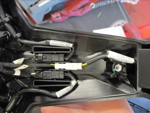
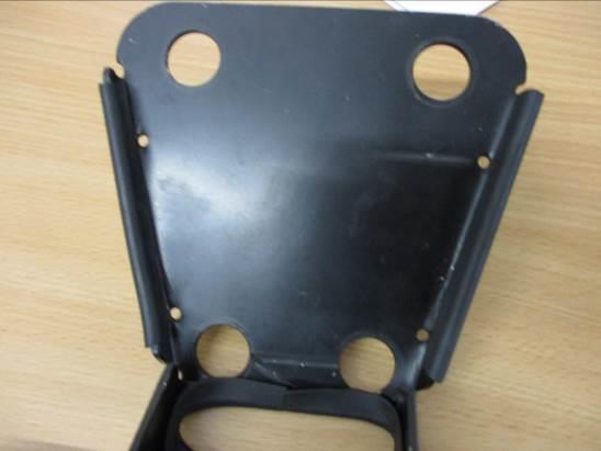
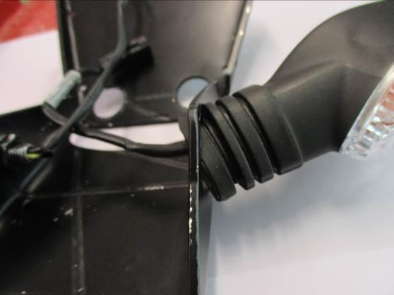
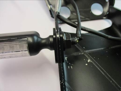
6 PICTURE 16 PICTURE 17 Page 6 PICTURE 18 FITTING INSTRUCTIONS Remove the seat using the keys. Remove the five bolts arrowed in pictures 1 and 2. Remove the plastic cable cover/indicator clamp plate. Remove the four bolts arrowed in picture 3. Carefully lower the original licence plate bracket as shown in picture 4. Disconnect the three wiring plug sockets for the licence plate illuminator and indicators as arrowed in picture 5 (you will have to cut the several cable ties). Remove the four metal spacers as shown in picture 6. Remove the four rubber mounting bushes as shown in picture 7. Fit the four rubber mounting bushes to the new licence plate bracket (item 1) as shown in picture 8. Fit the four metal spacers into the four rubber mounting bushes already fitted to the new licence plate bracket (item 1) as shown in picture 9. Fit the four new mounting spacers (item 4) over the original metal spacers as shown in picture 10 (a small amount of adhesive may be used to keep these spacers in position). Cut the rubber edging strip into suitable lengths and stick in position to the cover (item 5) and the new licence plate bracket (item 1) as arrowed in pictures 11 and 12. Fit the new licence plate illuminator (item 8) to the new licence plate bracket (item 1) as shown in pictures 13 and 14 (please use the provided heat shrink (item 11) to protect the wiring). PLEASE NOTE YOU WILL NEED TO GLUE THE LIGHT SHROUD TO THE LED LICENCE PLATE ILLUMINATOR USING SUPER GLUE. If reusing the original indicators Cut the cable ties securing the wiring and remove the indicator (please note which side it came off). Repeat the above to remove the other indicator (please note the relevant sides). Gently squeeze the indicator stem and push through the shape aperture in the new licence plate bracket (item 1) as shown in picture 15 (a small amount of silicon grease or liquid detergent helps in this process Fit the indicators to the new licence plate bracket (item 1) as they were mounted originally (ensure they are fitted on the correct sides). Route the wiring as original 6
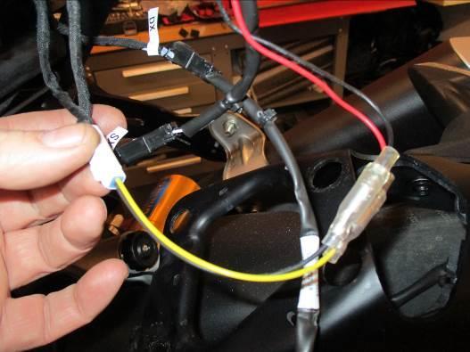
7 Page 7 Reconnect the indicators to the original wiring plug sockets. It is a good idea to check the operation of the licence plate illuminator and indicators at this stage (if the licence plate illuminator fails to light please swap the bullet connectors over). If fitting the mini indicators ( product code RG370=bulb, RG371=LED or RG372 for Aero LED Fit the indicators of choice to the new licence plate bracket (item 1) ( mini indicator product code RG370 for bulb type and RG371 for LED type or RG372 for Aero Style led type) through the holes in one of the indicator adaptors (item 3) so the shaped spigot fits into the bracket then fit another of the indicator adaptors onto the exposed end of the indicator stem and secure and tighten the nut (please use the provided heat shrink (item 11) to protect the wiring) as shown in picture 17. Repeat for the other indicator. Offer this assembly into position as shown in the top pictures. Use the four new button head bolts (items 2) with the original washers to secure the assembly in position. Route the wiring as original. Connect the licence plate illuminator using the supplied wiring connector (item 15) to the original wiring plug socket. Connect the Mini Indicators using the supplied wiring connectors (items 14) to the original wiring plug socket. Plug it into the loom to check at this stage (if operation fails, swap the bullet connections around). (Please use the heat-shrink (item 11) to protect the new indicator wires). It is a good idea at this point to turn the ignition on and check for the correct operation of all lights. Fit the cover (item 5) using the M4 bolts and washers (items 6 and 7). Use the supplied cable ties (items 12 and 13) and self-adhesive cable clips (item 9) to secure and tidy the wiring to the bracket. Remove the two bolts arrowed in picture 18. Position the infill panel (item 17) into the plastic undertray and secure using the original bolts as shown in picture 18 Re-fit the licence plate (it may require drilling). IMPORTANT: IF FITTING A FULL-SIZE LICENCE PLATE AND PLACING IT FAR DOWN ON THE LICENCE PLATE HANGER, THERE IS A SMALL CHANCE OF THE LICENCE PLATE HITTING THE BACK WHEEL UNDER HEAVY LOAD AND OVER LARGE BUMPS IN THE ROAD. IT IS YOUR RESPONSIBILITY TO CHECK FOR THIS POSSIBILITY AND TAKE AVOIDING ACTION. FAILURE TO CHECK THIS COULD RESULT IN SERIOUS INJURY OR DAMAGE. Refit the seat. Depending on local laws, attach enclosed red reflector (item 16) in an appropriate location. Please test the indicators, rear light and licence plate illuminator before riding. Digital copies of these instructions are available to download from GENERAL TORQUE SETTINGS M4 BOLT = 8Nm M5 BOLT = 12Nm M6 BOLT = 15Nm M8 BOLT = 20Nm M10 BOLT = 40Nm ISSUE 1 13/06/2018 (DM) 7
8 Page 8 CONSUMER NOTICE The catalogue description and any exhibition of samples are only broad indications of the Products and may make design changes which do not diminish their performance or visual appeal and supplying them in such state shall conform to the order. The Buyer acknowledges no representation or warranty (other than as to title) has been given or will apply to the Products other than those in s order or confirmation and the Buyer confirms it has chosen the Products as being of merchantable quality and suitable for its particular purposes. Where fits the Products or undertakes other services it shall exercise reasonable skill and care and rectify any fault free of charge unless the workmanship has been disturbed. The Buyer is responsible for ensuring that the warranty on the motorcycle is not affected by the fitting of the Products. On return of any defective Products shall at its option either supply a replacement or refund the purchase money but shall not be liable if the Products have been modified or used or maintained otherwise than in accordance with s or manufacturer s instructions and good engineering practice or if the defect arises from accident or neglect. Other than identified above and subject to not limiting its liability for causing death and personal injury, it shall not be liable for indirect or consequential loss and otherwise its liability shall be limited to the amounts paid by the Buyer for the Products or the fitting or service concerned. These terms do not affect the Buyer s statutory rights. RETURNS POLICY (NON-FAULTY GOODS) Returns must be pre-authorised (if not pre-authorised the return will be rejected). Goods may only be returned direct to us if they were purchased direct from us (customer must prove if necessary). Otherwise to be returned to original vendor. Goods must be in re-sellable condition, in the opinion of. All returns are subject to a 25% restocking and handling fee (25% of the gross value exc. P&P at the prevailing price at time of purchase). The customer must pay any and all carriage charges. No returns of discontinued products, unless within 14 days of purchase. This policy does not affect your statutory rights and does not refer to faulty goods. 8
9 Page 9 NOTICE DE MONTAGE BK SUPPORT DE PLAQUE Ducati Monster 821 '18-, 1200 (S) '17- & 1200R '18- pour Ducati Monster 821 (2018) Le kit contient les articles exposés ci-dessous, vérifier que toutes les pièces soient présentes avant de procéder au montage. La façon dont le kit est emballé ne correspond pas forcément à la façon de monter les pièces sur la moto. LES PARTIES PRESENTEES PEUVENT ETRE UNIQUEMENT REPRESENTATIVES (POUR LA CLARTE DES INSTRUCTIONS UNIQUEMENT
10 Page LÉGENDE ARTICLE 1 = PLAQUE DE FIXATION DE LA PLAQUE D IMMATRICULATION (TB0249BK- PARTIE 1) (x1). ARTICLE 2 = M8x30mm BOULONS (x4). ARTICLE 3 = ADAPTATEURS DE MINI CLIGNOTANT (I0033) (x4). ARTICLE 4 = ENTRETOISES DE FIXATION (S1121) (x4). ARTICLE 5 = CACHE (TB0224BK-PARTIE 2) (x1). ARTICLE 6 = M4x5mm BOULONS (x2). ARTICLE 7 = M4 RONDELLES (x2). ARTICLE 8 = ASSEMBLAGE FEU DE PLAQUE (LA0002) (x1). ARTICLE 9 = CLIPS CÂBLE AUTOCOLLANT (x4). ARTICLE 10 = JOINT DE BORD EN CAOUTCHOUC (SRS002) (500mm DE LONG) (x1). ARTICLE 11 = 180mm LONGUEUR DE MANCHON THERMO RÉTRACTABLE (x3). ARTICLE 12 = COLLIER DE SERRAGES (x4). ARTICLE 13 = PETIT COLLIER DE SERRAGES (x8). ARTICLE 14 = CLIGNOTANTCONNECTORS (CON0004) (x2). ARTICLE 15 = FEU DE PLAQUE CONNECTOR (CON0014) (x1). ARTICLE 16 = REFLECTEUR (REFLECTEUR 1) (x1). ARTICLE 17 = PANNEAU INTERNE (TB0249BK-PART 2) (x1). Notez que si les kits sont emballés avec des rondelles en caoutchouc servant à tenir les composants, ces rondelles doivent être jetées! OUTILS REQUIS Clés Allen 3, 4 et 6mm. Pinces électriques. Un peu de superglue. 10
11 Page 11 NOTICE DE MONTAGE Enlever le siège à l aide des clés. Enlever les 5 boulons, voir photos 1 et 2. Enlever câble cache/plaque de fixation clignotant. Enlever les 4 boulons, voir photo 3. Baisser le support de plaque d origine délicatement, voir photo 4. Déconnecter les 3 prises de fils du feu de plaque et les clignotants, voir photo 5 (vous devrez couper les colliers de serrage). Enlever les 4 entretoises métalliques, voir photo 6. Enlever les 4 buissons de fixation en caoutchouc, voir photo 7. Monter les 4 buissons de fixation en caoutchouc sur le nouveau support de plaque (article 1), voir photo 8. Insérer les 4 entretoises métalliques dans les 4 buissons de fixation en caoutchouc déjà montés sur le nouveau support de plaque (article 1), voir photo 9. Insérer les 4 nouvelles entretoises de fixation (article 4) sur les entretoises métalliques d origine, voir photo 10 (un peu d adhésif peut être utilisé pour fixer la position des entretoises). Couper le bandeau en caoutchouc en longueurs raisonnables puis collez les en position sur le cache (article 5) et le nouveau support de plaque (article 1) voir photos 11 et 12. Monter le nouveau feu de plaque (article 8) sur le nouveau support de plaque (article 1) voir photos 13 et 14 (utiliser la longueur de manchon thermo rétractable (article 11) pour protéger les fils). NOTEZ QUE VOUS DEVREZ COLLER LE LINCEUL DE FEU SUR LE FEU DE PLAQUE À LED EN UTILISANT DE LA SUPER GLUE. Si vous réutilisez les clignotants d origine Couper les colliers de serrage qui fixent le fil puis enlever le clignotant (notez de quel côté il est parti). Répéter l étape du dessus pour enlever l autre clignotant (notez le côté). Tordre légèrement la tige de clignotant puis pousser dans l ouverture du support de plaque (article 1), voir photo 15 (un peu de graisse de silicone ou liquide détergent aide ce process). Monter les clignotants sur le nouveau support de plaque (article 1) en procédant à l inverse de la façon dont ils ont été enlevés (veiller à ce qu ils soient montés du bon côté). Router le fil comme à l origine. Reconnecter les clignotants sur les prises de fil d origine. A ce stade, il est bon de vérifier que le feu de plaque et les clignotants fonctionnent correctement (Si le feu de plaque ne s allume pas, tournez les connecteurs). Si vous montez les mini clignotants ( code produit RG370=ampoule, RG371=LED ou RG372 pour LED latérale Montez les clignotants de votre choix sur le nouveau support de plaque (article 1) ( code produit mini clignotant RG370 pour type ampoule et RG371 pour type LED ou RG372 pour LED latérale) dans les trous d un des adaptateurs de clignotant (article 3) de façon à ce que le robinet se place dans le support puis monter un autre adaptateur de clignotant sur l extrémité de la tige de clignotant puis fixer et serrer l écrou (utiliser la 11
12 Page 12 longueur de manchon thermo rétractable (article 11) pour protéger le fil) voir photo 17. Répéter cela pour l autre clignotant. Monter l ensemble en position comme indiqué sur les photos du dessus. Utiliser les 4 nouveaux boulons (articles 2) avec les rondelles d origine pour fixer l ensemble en position. Router le fil comme à l origine. Connecter le feu de plaque en utilisant le connecteur de fil fourni (article 15) sur la prise de fil d origine. Connecter les mini clignotants en utilisant les connecteurs fournis (articles 14) sur la prise de fil d origine. Branchez la dans le faisceau pour vérifier le fonctionnement (si l éclairage échoue, tournez les connecteurs). (Utiliser la longueur de manchon thermo rétractable (article 11) pour protéger les fils du nouveau clignotant). A ce stade, il est bon de vérifier que le feu de plaque et les clignotants fonctionnent correctement. Monter le cache (article 5) en utilisant les boulons M4 et rondelles (articles 6 et 7). Utiliser les colliers de serrage fournis (articles 12 et 13) et les clips câble autocollants (article 9) pour fixer le fil au support. Enlever les 2 boulons indiqués sur la photo 18. Positionner le panneau interne (article 17) dans le sous plateau plastique puis fixer à l aide des boulons d origine, voir photo 18 Réinstaller le siège et la plaque (peut nécessiter un perçage). IMPORTANT : Si vous installez une grosse plaque, il y a un risque que la plaque entre en contact avec la roue arrière en cas de choc sur la route (bosse, grosse charge etc..). Il est de votre responsabilité de vérifier que cela ne puisse pas se produire. Ne pas effectuer ces vérifications peut entrainer des dommages ainsi que des blessures graves pour le pilote. Remonter le siège. Selon les lois locales, attacher le réflecteur rouge (article 11) à l endroit approprié. Tester le feu de plaque, les clignotants, ainsi que l ensemble des feux avant de prendre la route. Digital copies of these instructions are available to download from GENERAL TORQUE SETTINGS M4 BOULON = 8Nm M5 BOULON = 12Nm M6 BOULON = 15Nm M8 BOULON = 20Nm M10 BOULON = 40Nm ISSUE 1 13/06/2018 (DM) 12
13 Page 13 CONSUMER NOTICE The catalogue description and any exhibition of samples are only broad indications of the Products and may make design changes which do not diminish their performance or visual appeal and supplying them in such state shall conform to the order. The Buyer acknowledges no representation or warranty (other than as to title) has been given or will apply to the Products other than those in s order or confirmation and the Buyer confirms it has chosen the Products as being of merchantable quality and suitable for its particular purposes. Where fits the Products or undertakes other services it shall exercise reasonable skill and care and rectify any fault free of charge unless the workmanship has been disturbed. The Buyer is responsible for ensuring that the warranty on the motorcycle is not affected by the fitting of the Products. On return of any defective Products shall at its option either supply a replacement or refund the purchase money but shall not be liable if the Products have been modified or used or maintained otherwise than in accordance with s or manufacturer s instructions and good engineering practice or if the defect arises from accident or neglect. Other than identified above and subject to not limiting its liability for causing death and personal injury, it shall not be liable for indirect or consequential loss and otherwise its liability shall be limited to the amounts paid by the Buyer for the Products or the fitting or service concerned. These terms do not affect the Buyer s statutory rights. RETURNS POLICY (NON-FAULTY GOODS) Returns must be pre-authorised (if not pre-authorised the return will be rejected). Goods may only be returned direct to us if they were purchased direct from us (customer must prove if necessary). Otherwise to be returned to original vendor. Goods must be in re-sellable condition, in the opinion of. All returns are subject to a 25% restocking and handling fee (25% of the gross value exc. P&P at the prevailing price at time of purchase). The customer must pay any and all carriage charges. No returns of discontinued products, unless within 14 days of purchase. This policy does not affect your statutory rights and does not refer to faulty goods. 13
14 MONTAGEANLEITUNG FÜR BK KENNZEICHENHALTER Kennzeichenhalter für Ducati Monster 821 '18-, 1200 (S) '17- & 1200R '18- sowie für Ducati Monster 821 (2018) Page 14 ALLE KIT-TEILE SIND UNTEN ABGEBILDET UND GEKENNZEICHNET. BEVOR SIE MIT DER MONTAGE BEGINNEN, ÜBERPRÜFEN SIE, DASS ALLE TEILE VORHANDEN SIND. Hinweis: Die Verpackung der Teile stellt nicht die Reihenfolge der Montage dar. DIE UNTEN ABGEBILDETEN TEILE DIENEN LEDIGLICH ZUR ERKLÄRUNG
15 Page LIEFERUMFANG ARTIKEL 1 = KENNZEICHENHALTER (TB0249BK-TEIL 1) (x1) ARTIKEL 2 = M8x30mm INBUSSCHRAUBEN (x4) ARTIKEL 3 = ADAPTER FÜR DIE MINIBLINKER (I0033) (x4) ARTIKEL 4 = DISTANZHALTER FÜR MONTAGE (S1121) (x4) ARTIKEL 5 = ABDECKUNG (TB0249BK-TEIL 2) (x1) ARTIKEL 6 = M4x5mm INBUSSCHRAUBEN (x2) ARTIKEL 7 = M4 UNTERLEGSCHEIBEN (x2) ARTIKEL 8 = KENNZEICHENBELEUCHTUNG (LA0002) (x1) ARTIKEL 9 = SELBSTKLEBENDE KABELCLIPS (x4) ARTIKEL 10 = KANTENSCHUTZ (SRS002) (500mm) (x1) ARTIKEL 11 = 180mm SCHRUMPFSCHLAUCH (x3) ARTIKEL 12 = GROSSE KABELBINDER (x4) ARTIKEL 13 = KLEINE KABELBINDER (x8) ARTIKEL 14 = KABELVERBINDER FÜR DIE BLINKER (CON0004) (x2) ARTIKEL 15 = KABELVERBINDER FÜR DIE KENNZEICHENBELEUCHTUNG (CON0004) (x1) ARTIKEL 16 = RÜCKSTRAHLER (REFL 1) (x1) ARTIKEL 17 = VERKLEIDUNGSTEIL (x1) Hinweis für Kits mit Plastikunterlegscheiben an den Schrauben Diese Plastikunterlegscheiben werden nicht für den Einbau benötigt! SIE BENÖTIGEN FOLGENDES WERKZEUG Satz Inbusschlüssel mit 3, 4 & 6 mm Inbusschlüsseln Elektroniker Zange etwas Sekundenkleber MONTAGEANLEITUNG Entfernen Sie den Sitz (der Schlüssel wird hierfür benötigt). Entfernen Sie die fünf Schrauben, die in den Abbildungen 1 und 2 gekennzeichnet sind. Entfernen Sie die Kabelabdeckung/Klemmplatte aus Kunststoff für die Blinker: Entfernen Sie die vier Schrauben, die in Abbildung 3 gekennzeichnet sind. Vorsichtig den original Kennzeichenhalter herunterlassen siehe Abbildung 4. Trennen Sie die drei Steckverbindungen für die Blinker und die Kennzeichenbeleuchtung wie in Abbildung 5 abgebildet - (die Kabelbinder müssen hierbei durchgeschnitten werden). 15
16 Page 16 Entfernen Sie die vier Metall-Distanzhalter, wie in Abbildung 6 abgebildet. Entfernen Sie die vier Gummitüllen siehe Abbildung 7. Montieren Sie die vier Gummitüllen am neuen Kennzeichenhalter (Artikel 1), wie in Abbildung 8 abgebildet. Montieren Sie die vier Metall-Distanzhalter in den vier bereits am neuen Kennzeichenhalter montierten Gummitüllen siehe Abbildung 9. Montieren Sie die vier neuen Distanzhalter (Artikel 4) auf den original Metall- Distanzhaltern wie in Abbildung 10 abgebildet (etwas Klebestoff darf benutzt werden, um diese Distanzhalter in Position zu fixieren). Den Kantenschutz in passende Längen schneiden und an der Abdeckung (Artikel 5) und am neuen Kennzeichenhalter (Artikel 1) anbringen siehe Abbildungen 11und 12. Montieren Sie die neue Kennzeichenbeleuchtung (Artikel 8) am neuen Kennzeichenhalter (Artikel 1) wie in den Abbildungen 13 und 14 abgebildet (bitte den mitgelieferten Schrumpfschlauch (Artikel 11) verwenden, um die Kabel zu schützen). BITTE BEACHTEN: VOR DER MONTAGE MUSS DIE LICHTABDECKUNG MIT SEKUNDENKLEBER AN DER LED-KENNZEICHENBELEUCHTUNG ANGEKLEBT WERDEN. Wenn Sie die Originalblinker wiederverwenden Die Kabelbinder, die die Verkabelung fixieren durchschneiden und den Blinker entfernen (bitte die entsprechende Seite notieren). Wiederholen Sie diesen Schritt, um den anderen Blinker ebenfalls zu entfernen (die Seite ebenfalls notieren). Den Blinker vorsichtig durch die geformte Öffnung im neuen Kennzeichenhalter (Artikel 1) drücken, wie in Abbildung 15 abgebildet. (die Verwendung von etwas Silikonfett oder Spülmittel hilft bei der Montage). Montieren Sie die Blinker am neuen Kennzeichenhalter (Artikel 1) wie ursprünglich (bitte darauf achten, dass sie an der richtigen Seite angebracht werden). Verlegen Sie die Kabel wir ursprünglich wieder. Verbinden Sie die Blinker mit den original Steckverbindern. Es empfiehlt sich, zum jetzigen Zeitpunkt die Funktion der Beleuchtung (Blinker und Kennzeichenhalter-Beleuchtung) zu überprüfen (falls die Kennzeichenbeleuchtung nicht funktionieren sollte, tauschen Sie die Kabelverbinder untereinander). Wenn Sie Miniblinker montieren ( Artikel-Nr. RG370= mit Glühbirne, RG371=LED oder RG372 für Aero LED Montieren Sie die Blinker Ihrer Wahl am neuen Kennzeichenhalter (Artikel 1) ( Miniblinker Artikel-Nr. RG370 = mit Glühbirne, RG371= LED oder RG372 = Aero LED) einen Blinker an der Öffnung eines Miniblinker-Adapters (Artikel 3) montieren, so dass der Zapfen in die Halterung passt, danach noch einen Adapter am hervorstehenden Ende des Blinkers anbringen und anschließend den Blinker mit einer Mutter befestigen (bitte verwenden Sie den mitgelieferten Schrumpfschlauch (Artikel 11), um die Kabel zu schützen) siehe Abbildung 17. Wiederholen Sie diesen Schritt mit dem zweiten Blinker. Diese Einheit in Position bringen, wie in den oberen Abbildungen abgebildet. Benutzen Sie die vier neuen Inbusschrauben (Artikels 2) zusammen mit den original Unterlegscheiben, um die Einheit in Position zu befestigen. Verlegen Sie die Kabel wie ursprünglich wieder. Den Kabelverbinder (Artikel 15) benutzen, um die Kennzeichenbeleuchtung mit dem original Steckverbinder zu verbinden. Die mitgelieferten Kabelverbinder (Artikel 14) verwenden, um die Miniblinker mit dem original Steckverbinder zu verbinden. Am Kabelbaum anschließen und danach die 16
17 Page 17 Funktion der Blinker und Kennzeichenbeleuchtung überprüfen (wenn sie nicht funktionieren sollte, einfach die Kabelverbinder untereinander tauschen). Bitte den Schrumpfschlauch (Artikel 11) benutzen, um die Kabel zu schützen. Es empfiehlt sich, zu diesem Zeitpunkt die Zündung einzuschalten und die ordnungsgemäße Funktion der kompletten Beleuchtung zu überprüfen. Montieren Sie die Abdeckung (Artikel 5) mit den M4 Schrauben und Unterlegscheiben (Artikel 6 und 7). Benutzen Sie die mitgelieferten Kabelbinder (Artikel 12 und 13) und selbstklebende Kabelclips (Artikel 9), um die Kabel am Kennzeichenhalter zu befestigen. Entfernen Sie die zwei Schrauben, die in Abbildung 18 gekennzeichnet sind. Das Verkleidungsteil (Artikel 17) in der unteren Abdeckung positionieren und mit den Originalschrauben befestigen siehe Abbildung 18 Montieren Sie das amtliche Kennzeichen wieder (Bohrungen im Kennzeichen evtl. notwendig). WICHTIG: WENN EIN GROSSES KENNZEICHEN ZU WEIT NACH UNTEN MONTIERT WIRD, BESTEHT BEI SCHWERER LAST / DURCH GROSSE BODENWELLEN EIN GERINGES RISIKO, DASS DAS KENNZEICHEN AN DAS HINTERRAD STOSSEN KANN. ES LIEGT IN IHRER VERANTWORTUNG DIES ZU ÜBERPRÜFEN UND, WENN NOTWENDIG, VORBEUGENDE MASSNAHMEN ZU ERGREIFEN. DIE NICHTBEACHTUNG DIESES SICHERHEITSHINWEIS KANN ZU SCHWEREN VERLETZUNGEN FÜHREN. Montieren Sie den Sitz wieder. Entsprechend der gesetzlichen Vorschriften, den mitgelieferten Rückstrahler (Artikel 16) anbringen. Überprüfen Sie die Funktion der Beleuchtung (Blinker und Kennzeichenhalter- Beleuchtung) vor Gebrauch des Fahrzeuges. Eine digitale Version dieser Montageanleitung kann auf folgender Seite heruntergeladen werden: MAX. ANZUGSDREHMOMENTE: M4 SCHRAUBE = 8Nm M5 SCHRAUBE = 12Nm M6 SCHRAUBE = 15Nm M8 SCHRAUBE = 20Nm M10 SCHRAUBE = 40Nm AUSGABE 1 13/06/2018 (DM) CONSUMER NOTICE The catalogue description and any exhibition of samples are only broad indications of the Products and may make design changes which do not diminish their performance or visual appeal and supplying them in such state shall conform to the order. The Buyer acknowledges no representation or warranty (other than as to title) has been given or will apply to the Products other than those in s order or confirmation and the Buyer confirms it has chosen the Products as being of merchantable quality and suitable for its particular purposes. Where fits the Products or undertakes other services it shall exercise reasonable skill and care and rectify any fault free of charge unless the workmanship has been disturbed. The Buyer is responsible for ensuring that the warranty on the motorcycle is not affected by the fitting of the Products. On return of any defective Products shall at its option either supply a replacement or refund the purchase money but shall not be liable if the Products have been modified or used or maintained otherwise than in accordance with s or manufacturer s instructions and good engineering practice or if the defect arises from accident or neglect. Other than identified above and subject to not limiting its liability for causing death and personal injury, it shall not be liable for indirect or consequential loss and otherwise its liability shall be limited to the amounts paid by the Buyer for the Products or the fitting or service concerned. These terms do not affect the Buyer s statutory rights. RETURNS POLICY (NON-FAULTY GOODS) Returns must be pre-authorised (if not pre-authorised the return will be rejected). Goods may only be returned direct to us if they were purchased direct from us (customer must prove if necessary). Otherwise to be returned to original vendor. Goods must be in re-sellable condition, in the opinion of. All returns are subject to a 25% restocking and handling fee (25% of the gross value exc. P&P at the prevailing price at time of purchase). The customer must pay any and all carriage charges. No returns of discontinued products, unless within 14 days of purchase. This policy does not affect your statutory rights and does not refer to faulty goods. 17
Fitting Instructions for RAD0171BK Radiator Guard YAMAHA MT
 Fitting Instructions for RAD0171BK Radiator Guard YAMAHA MT-07 2014- In This Kit There Should Be 1x Radiator Guard (RAD0171BK). 4x M6 Nyloc Nuts. 4x M6 Washers. 2x 100mm Lengths of self-adhesive Foam.
Fitting Instructions for RAD0141BK Radiator Guard KAWASAKI ZX-6R
 Fitting Instructions for RAD0141BK Radiator Guard KAWASAKI ZX-6R 636 2013 In This Kit There Should Be 1 x Radiator Guard (RAD0141BK) 2 x 100mm Lengths of self-adhesive Foam. 4 x 4mm Cable Ties x 220mm
FITTING INSTRUCTIONS FOR CP0404BL/WH NO-CUT AERO CRASH PROTECTORS HUSQVARNA 701 ENDURO/SUPERMOTO 2016-
 FITTING INSTRUCTIONS FOR BL/WH NO-CUT AERO CRASH PROTECTORS HUSQVARNA 701 ENDURO/SUPERMOTO 2016- Page 1 PICTURE A PICTURE B REAR OF BIKE FRONT OF BIKE PICTURE C THIS KIT CONTAINS THE ITEMS PICTURED AND
FITTING INSTRUCTIONS FOR BLP0032SI REAR FOOTREST BLANKING PLATES YAMAHA MT
 FITTING INSTRUCTIONS FOR BLP0032SI REAR FOOTREST BLANKING PLATES YAMAHA MT-07 2014- Please note that the way the kit is packed does not necessarily represent the way of mounting to the bike THE PARTS SHOWN
FITTING INSTRUCTIONS FOR CP0393BL AERO CRASH PROTECTORS SUZUKI GSX-S
 Page1 FITTING INSTRUCTIONS FOR BL AERO CRASH PROTECTORS SUZUKI GSX-S 1000 2015- PICTURE A PICTURE B REAR OF BIKE FRONT OF BIKE PICTURE C THIS KIT CONTAINS THE ITEMS PICTURED AND LABELLED BELOW. DO NOT
Fitting Instructions for SRG0034 Radiator Guard Radiator Guard KAWASAKI VERSYS
 Fitting Instructions for SRG0034 Radiator Guard Radiator Guard KAWASAKI VERSYS 650 2015- In This Kit There Should Be 1x Radiator Guard. 1x Spacer. 1 x M6 Bolt. 1x M6 Nut and Washer. 6 x Cable/Zip Ties.
Fitting Instructions for OCG0014BK Oil Cooler Guard Ducati Monster 1100 / 1100S / 1100EVO & 795/796 '09-
 Fitting Instructions for OCG0014BK Oil Cooler Guard Ducati Monster 1100 / 1100S / 1100EVO & 795/796 '09- In This Kit There Should Be 1x Oil Cooler Guard (OCG0014) 1x M6 x 25mm Long Button Head Bolt 1x
FITTING INSTRUCTIONS FOR PKS0057SI KICKSTAND SHOE MV Augusta F
 FITTING INSTRUCTIONS FOR PKS0057SI KICKSTAND SHOE MV Augusta F4 1000 04- Please note that the way the kit is packed does not necessarily represent the way of mounting to the bike. THE PARTS SHOWN MAY BE
Fitting Instructions for RAD0164 BK/OR Radiator Guard KTM 390 DUKE 2013
 Fitting Instructions for RAD0164 BK/OR Radiator Guard KTM 390 DUKE 2013 In This Kit There Should Be 1x Radiator Guard (RAD0164BK/OR) 4 x Cable/Zip Tie 2x 100mm Lengths of self adhesive Foam To fit the
FITTING INSTRUCTIONS FOR LP0151BK LICENCE PLATE BRACKET HONDA CBR500R/ CB500X and CB500F 2013
 FITTING INSTRUCTIONS FOR LP0151BK LICENCE PLATE BRACKET HONDA CBR500R/ CB500X and CB500F 2013 Page 1 THIS KIT CONTAINS THE ITEMS PICTURED AND LABELLED BELOW. DO NOT PROCEED UNTIL YOU ARE SURE ALL PARTS
In this kit there should be: 1 x Engine Case Cover (ECC0085) 2 x M6x28mm long button head bolts PLEASE READ THESE INSTRUCTIONS FULLY BEFORE STARTING
 2 x M6x28mm long button head bolts PLEASE READ THESE INSTRUCTIONS FULLY BEFORE STARTING") FITTING INSTRUCTIONS FOR ECC0085 LHS WATER PUMP COVER TO FIT ALL WATER COOLED DUCATI S REMOVE REMOVE In this kit there should be: 1 x Engine Case Cover (ECC0085) 2 x M6x28mm long button head bolts PLEASE
FITTING INSTRUCTIONS FOR ECC0085 LHS WATER PUMP COVER TO FIT ALL WATER COOLED DUCATI S REMOVE REMOVE In this kit there should be: 1 x Engine Case Cover (ECC0085) 2 x M6x28mm long button head bolts PLEASE
FITTING INSTRUCTIONS FOR LP0139BK LICENCE PLATE BRACKET HONDA CBR600RR 2013-
 FITTING INSTRUCTIONS FOR LP0139BK LICENCE PLATE BRACKET HONDA CBR600RR 2013- THIS KIT CONTAINS THE ITEMS PICTURED AND LABELLED BELOW. DO NOT PROCEED UNTIL YOU ARE SURE ALL PARTS ARE PRESENT. Please note
FITTING INSTRUCTIONS FOR LP0256BK LICENCE PLATE BRACKET DUCATI SCRAMBLER
 Page 1 of 19 FITTING INSTRUCTIONS FOR BK LICENCE PLATE BRACKET DUCATI SCRAMBLER 1100 2018 THIS KIT CONTAINS THE ITEMS PICTURED AND LABELLED BELOW. DO NOT PROCEED UNTIL YOU ARE SURE ALL PARTS ARE PRESENT.
Fitting Instructions for DG0016BK DOWNPIPE GRILLE HONDA CBR600RR 2013
 Fitting Instructions for DG0016BK DOWNPIPE GRILLE HONDA CBR600RR 2013 In This Kit There Should Be 1x Downpipe Grille (DG0016BK) Picture 1 Picture 2 Picture 3 Picture 4 Picture 5 Picture 6 TOOLS REQUIRED
Fitting Instructions for RSET14BK Adjustable Rearsets Aprilia RSV4R and Factory ( 09-)
") Fitting Instructions for RSET4BK Adjustable Rearsets Aprilia RSV4R and Factory ( 09-) First remove the original Aprilia rearsests. Install on the gear shaft connector () onto the gear shaft. Then connect
Fitting Instructions for RSET4BK Adjustable Rearsets Aprilia RSV4R and Factory ( 09-) First remove the original Aprilia rearsests. Install on the gear shaft connector () onto the gear shaft. Then connect
FITTING INSTRUCTIONS FOR RGH0002BK REAR WHEEL HUGGER YAMAHA FZ8
 FITTING INSTRUCTIONS FOR RGH0002BK REAR WHEEL HUGGER YAMAHA FZ8 THIS KIT CONTAINS THE ITEMS PICTURED AND LABELLED BELOW. DO NOT PROCEED UNTIL YOU ARE SURE ALL PARTS ARE PRESENT. Please note that the way
FITTING INSTRUCTIONS FOR RSET12BK ADJUSTABLE REARSETS FOR TRIUMPH DAYTONA 675 ( )
") FITTING INSTRUCTIONS FOR RSET12BK ADJUSTABLE REARSETS FOR TRIUMPH DAYTONA 675 (2008-2011) First remove the original Triumph rearsests. Then remove the engine axle and insert it from the otherside (from
FITTING INSTRUCTIONS FOR RSET12BK ADJUSTABLE REARSETS FOR TRIUMPH DAYTONA 675 (2008-2011) First remove the original Triumph rearsests. Then remove the engine axle and insert it from the otherside (from
PICTURE C Please note that the way the kit is packed does not necessarily represent the way of mounting to the bike
 FITTING INSTRUCTIONS FOR BL NO CUT CRASH PROTECTORS BMW S1000R 2014 Page 1 TOWARDS REAR OF BIKE TOWARDS FRONT OF BIKE PICTURE C Please note that the way the kit is packed does not necessarily represent
FITTING INSTRUCTIONS FOR CP0368BL AERO CRASH PROTECTORS DUCATI MONSTER & MONSTER
 Page1 FITTING INSTRUCTIONS FOR BL AERO CRASH PROTECTORS DUCATI MONSTER 1200 14- & MONSTER 821 14- Picture A Picture B THIS KIT CONTAINS THE ITEMS PICTURED AND LABELLED BELOW. DO NOT PROCEED UNTIL YOU ARE
READ AND FOLLOW ALL SAFETY INSTRUCTIONS 1. DANGER RISK OF SHOCK DISCONNECT POWER BEFORE INSTALLATION
 UR Series LED Upgrade Kit Includes: 24" Linear Option IMPORTANT SAFEGUARDS When using electrical equipment, basic safety precautions should always be followed including the following: READ AND FOLLOW ALL
Specification Grade Contemporary Wall Mount/Technical Installation Data
 AVAILABLE CONFIGURATIONS RECESSED MOUNT SURFACE MOUNT MOUNTING REQUIREMENTS A. Recessed Mount: Minimum 4-Gang Box, 1-5/8 in. Deep (72.8 Cubic Inches) with 4-Gang Box Cover (20.3 Cubic Inches) B. Surface
60AZinkenverstellgeräte. 60A Ajusteurs de Fourches
 Parts Manual Ersatzteilliste Manuel de pièces détachées c 60A Fork Positioners 60AZinkenverstellgeräte 60A Ajusteurs de Fourches Last revision: 24/03/2011 cascade Parts Manual - 60A82017 35D Fork Positioner
VWR FOR SIEVING. Test sieve shakers and accessories. Ultrasonic sieving systems. Sample splitters. Test sieves. Standards.
 VWR FOR SIEVING Test sieve shakers and accessories Ultrasonic sieving systems Sample splitters Test sieves Standards Ultrasonic baths Useful accessories Available from P:0800 34 24 66 www.bio-strategy.com
INSTALLATION INSTRUCTIONS LED RETROFIT ASSEMBLY (LRA) Rev F
 Rev F") SAFETY S IMPORTANT SAFETY INFORMATION SUITABLE FOR DRY OR DAMP LOCATIONS. NOT FOR USE WITH PHASE CUT DIMMERS. Risk of shock. Disconnect power before installation. DANGER CONVIENT AUX EMPLACEMENTS HUMIDES.
SAFETY S IMPORTANT SAFETY INFORMATION SUITABLE FOR DRY OR DAMP LOCATIONS. NOT FOR USE WITH PHASE CUT DIMMERS. Risk of shock. Disconnect power before installation. DANGER CONVIENT AUX EMPLACEMENTS HUMIDES.
R185A STRAIGHT JACK EZ FIT TYPE. 1 5/8" CORRUGATED CABLE Series : ECO 7/16 TECHNICAL DATA SHEET 1 / 5 MATERIALS. PLATING (µm) COMPONENTS
 COMPONENTS") .. pn ao TECHNICAL DATA SHEET 1 / 5 All dimensions are in mm. COMPONENTS MATERIALS PLATING (µm) BODY CENTER CONTACT OUTER CONTACT INSULATOR GASKET OTHERS PARTS BRASS BRONZE PTFE SILICONE RUBBER BRASS BBR
.. pn ao TECHNICAL DATA SHEET 1 / 5 All dimensions are in mm. COMPONENTS MATERIALS PLATING (µm) BODY CENTER CONTACT OUTER CONTACT INSULATOR GASKET OTHERS PARTS BRASS BRONZE PTFE SILICONE RUBBER BRASS BBR
Captivate Illuminated Mirror Light
 ENGLISH WARNINGS & SAFETY INFORMATION: PLEASE READ CAREFULLY FRANÇAIS MISES EN GARDE ET SÉCURITÉ: SE IL VOUS PLAÎT LIRE ATTENTIVEMENT WARNING: RISK OF FIRE OR ELECTRIC SHOCK. LUMINAIRE WIRING AND ELECTRICAL
INSTALLATION INSTRUCTIONS MOONRING 1 LP1/MR1
 INSTALLATION INSTRUCTIONS MOONRING 1 LP1/MR1 Suspended, Ceiling LED n A 1035 22nd Avenue, Unit 1 Oakland, CA 94606 P 510.489.2530 E TalkToUs@alwusa.com W alwusa.com Safety & Warnings! 1. Read all instructions.
IMPORTANT SAFEGUARDS When using electrical equipment, basic safety precautions should always be followed including the following:
 ZR-RK Series LED Retrofit Troffer Kit Includes: ZR22RK and ZR24RK Standard and Emergency Luminaires IMPORTANT SAFEGUARDS When using electrical equipment, basic safety precautions should always be followed
MOONRING 1.5 MOONRING 3
 INSTALLATION INSTRUCTIONS MOONRING 1.5 MOONRING 3 MR1.5 & MR3 Suspended, Ceiling LED n A 1035 22nd Avenue, Unit 1 Oakland, CA 94606 P 510.489.2530 E TalkToUs@alwusa.com W alwusa.com Safety & Warnings!
Werkstattmobil Workshop trolley Poste mobile d atelier
 Technical Furniture Werkstattmobil Workshop trolley Poste mobile d atelier Assembly Instructions Bitte beachten Sie Please read A consulter imperativement Weitere Dokumentation beachten Refer to the other
Have a Bright Day! Nicholas Harmon President, Verilux, Inc.
 VF02 Dear Customer, Thank you for purchasing the Verilux EasyFlex Deluxe Natural Spectrum Floor Lamp. You have received a quality product, backed by a one year limited warranty. As a Verilux customer,
INSTALLATION INSTRUCTIONS LED Canopy Retrofit Kit
 INSTALLATION INSTRUCTIONS LED Canopy Retrofit Kit TRMUNV065ECxyyZ TRAUNV065ECxyyZ Installation Instructions subject to change without notice. Page 1 of 8 1.0 INSTALLATION WARNINGS 1. 2. 3. 4. 5. 6. "THIS
INSTRUCTION MANUAL - GUIDE D INSTALLATION H101 SHOWER / DOUCHE 12 / 2017 TUB / BAIGNOIRE
 INSTRUCTION MANUAL - GUIDE D INSTALLATION H101 SHOWER / DOUCHE 12 / 2017 TUB / BAIGNOIRE Please keep this manual and product code number for future reference and for ordering replacement parts if necessary.
Installation Guidelines
 Installation Guidelines 5000-10-0338-MAN CF Moto VERSION A WARNING Please read carefully each part of this document as well as the User Manual prior to assembling, installing and using the Track System.
INSTALLATION INSTRUCTIONS
 INDIGO-CLEAN TECHNOLOGY RETROFIT KIT INSTALLATION INSTRUCTIONS 1 IMPORTANT SAFETY INFORMATION Risk of shock. Disconnect power before installation. DANGER- RISQUE DE CHOC- COUPER L ALIMENTATION AVANT L
INSTALLATION INSTRUCTIONS SUPERPLANE 2.5. Suspended. A nd Avenue, Unit 1 Oakland, CA P E W alwusa.
 INSTALLATION INSTRUCTIONS SUPERPLANE 2.5 Suspended A 1035 22nd Avenue, Unit 1 Oakland, CA 94606 P 510.489.2530 E TalkToUs@alwusa.com W alwusa.com SP2.5S - Safety & Warnings! 1. Read all instructions. 2.
INSTALLATION INSTRUCTIONS LIGHTPLANE 3.5. LP3.5 Suspended LED. A nd Avenue, Unit 1. CA P E W alwusa.
 Oakland, INSTALLATION INSTRUCTIONS LIGHTPLANE 3.5 LP3.5 Suspended LED A 1035 22nd Avenue, Unit 1 n CA 94606 P 510.489.2530 E TalkToUs@alwusa.com W alwusa.com Safety & Warnings! 1. Read all instructions.
ZAZERI 48" ZAZERI 60"
 Installation alcôve A et installation en coin B Built-in A and corner B installation ZAZERI " ZAZERI 60" ZITTACLEAN " (5 / "~6 /6") (5mm~77mm) 60" (57 7/6"~5 5/" ) (59mm~9mm) "(9 /"~0 /") (75mm~77mm )
UB-2 2 Universal Button
 UB-2 2 Universal Button UB-2/LTUL Universal Button with Latching Timer ADA Compliant For UB-2/LTUL the enclosed timer is to be used and installed per the enclosed LT-1UL installation sheet. For access
VersaWall SlimLine 1750
 Index Stick built curtain wall 1 3/4"(44.5mm) profile Mur rideau avec profilé de 1 3/4"(44.5mm) Capped Couvercles à enclenchement Primary components - back sections Composantes principales - traverses
Cable Cubby 1202 and 1402 Installation Guide
 Cable Cubby 0 and 40 Installation Guide IMPORTANT: Go to www.extron.com for the complete user guide, installation instructions, and specifications. This guide provides instructions for an experienced technician
MRAD Universal Measuring Arm System For Optical/Magnetic and Fiber Optic Encoders
 Measuring Wheel Meauring Arm Encoder (Absolute or Incremetnal) Spring-loaded, adjustable measuring arm for universal applications Measuring wheels are utilized in combination with encoders to measure material
INSTALLATION GUIDE Works in double and single ended wiring.
 ISTAATIO GUIDE Works in double and single ended wiring. -1- Safety Precautions For your and others safety, please read the precaution carefully before installation: (1). Product should be installed by
ELV1abbccd-e. Color Temperature: 30 = 3000K White 35 = 3500K White 40 = 4000K White 45 = 4500K White 50 = 5000K White
 GE Lighting Immersion TM Elite LED Refrigerated Display Lighting End Mullion Lights for Vertical Cases Installation Guide ELV1abbccd-e Prefix: EL = Elite V = Vertical FD = French Door 1 = Generation Light
LUNERA VERTICAL E26 LED FLOODLIGHT LED Replacement for E26 Medium Base Floodlights Type B Ballast Bypassed
 Installation Guide LUNERA VERTICAL E26 LED FLOODLIGHT LED Replacement for E26 Medium Base Floodlights Type B Ballast Bypassed Installation Description The LUNERA VERTICAL E26 LED FLOODLIGHT is a line driven
Parent s Guide. This guide contains important information. Please keep it for future reference US
 Parent s Guide This guide contains important information. Please keep it for future reference. 91-003324-000 US INTRODUCTION The Stack & Tumble Elephant TM provides a silly twist on the classic ring stacker.
NL-FTPR150, FUNCTIONAL TRAINER ASSEMBLY INSTRUCTIONS
 NL-FTPR50, FUNCTIONAL TRAINER ASSEMBLY INSTRUCTIONS Specifications Weight = 55 lbs Packed in 9 Boxes Box = 44.5" x.5" x 7.5" = 2.22 ft³ = 56 lbs Box 2 = 46.5" x 6" x 6.5" = 2.80 ft³ = 76.5 lbs Box = 78.5"
Installation and Maintenance Instructions
 Installation and Maintenance Instructions Limited One Year Warranty T&S warrants to the original purchaser (other than for purposes of resale) that such product is free from defects in material and workmanship
AHP Blockzylinder mit langem Hub
 AHP Blockzylinder mit langem Hub AHP Block cylinder with long stroke AHP Vérins blocs avec course longue BRB 0 Wir bringen Qualität in Umlauf We set quality in motion ous faisons avancer la qualité Blockzylinder
FLY BABY U.S.MAIL. Radio control model R/C Flugmodell INSTRUCTION MANUAL MONTAGEANLEITUNG U.S.MAIL VERSION SPECIFICATIONS TECHNISCHE DATEN
 Radio control model R/C Flugmodell INSTRUCTION MANUAL MONTAGEANLEITUNG FLY BABY U.S.MAIL VERSION U.S.MAIL Item No. 1600133 SPECIFITIONS Wingspan 1210mm (49in.) Length 880mm (34.6 in.) Electric Motor (See
VA-4233-AGx Series Electric Valve Actuators
 Installation Instructions VA-4233 No. 1 Issue Date June 30, 2014 VA-4233-AGx Series Electric Valve Actuators Installation Refer to Figures 2 through 4 for proper actuator orientation before attempting
A1100 GUARDIAN OVERFILL PREVENTION VALVE (with Installation Kit)
") A1100 GUARDIAN OVERFILL PREVENTION VALVE (with 493192 Installation Kit) Assembly and Installation Instructions Important: Read these instructions completely and carefully before attempting to install and
A1100 GUARDIAN OVERFILL PREVENTION VALVE (with 493192 Installation Kit) Assembly and Installation Instructions Important: Read these instructions completely and carefully before attempting to install and
Diagnostic Test Kit Series P Series WARNING. for Polaris Robotic Cleaners
 Diagnostic Test Kit for Polaris Robotic Cleaners 93 94 95 Series P825 91 Series WARNING H0510700 Rev A The Diagnostic Box and included test cables are to be used solely for diagnosing Polaris Robotic Cleaners.
A1100 GUARDIAN OVERFILL PREVENTION SYSTEM
 A1100 GUARDIAN OVERFILL PREVENTION SYSTEM (with 493734S collar kit) Assembly and Installation Instructions (includes 566710S paper template) IMPORTANT: Read these instructions completely and carefully
Have a bright day! Nicholas Harmon President, Verilux, Inc.
 Model: VF02 Dear Customer, Thank you for purchasing the Verilux EasyFlex Deluxe Natural Spectrum Floor Lamp. You have received a quality product, backed by a one year limited warranty. As a Verilux customer,
WARNING AVERTISSEMENT
 Installation Guidelines Directives d installation 5000-05-0125-MAN Polaris WARNING Possibility of incompatibility between differential ratios. Before installation on this vehicle, it is *MANDATORY* to
General fitting instructions for Whiteline swaybars.
 General fitting instructions for Whiteline swaybars. Redranger Pty Limited 4 Warringah Close, Somersby, NSW 2250 Australia Ph: 61 2 4340 2355 Fax: 61 2 4340 2466 E-mail: sales@whiteline.com.au A.B.N. 99
Letter Band Phonics Jam
 Letter Band Phonics Jam TM Parent s Guide This guide contains important information. Please keep it for future reference. 91-003480-005 US INTRODUCTION Thank you for purchasing the Letter Band Phonics
LAVTBYGGENDE BAKMONTERT BESLAG
 Monteringsanvisning: LAVTYGGENE AKMONTERT ESLAG Har du spørsmål eller trenger du hjelp? Ring ar-o Garasjeporter AS på 55 11 42 10 3 mm 3/8" 1/2" 9/16" 3/8" 1/2" 9/16" #2 #2 4mm 8mm 10mm A 5718 5743 5421
. performance increase of up to 10.5 KW and 9 NM*) KIA/STI-1P KIA/STI-BRKT
 KIA/STI-1P KIA/STI-BRKT") Regelmaßige freiwillige Uberwachung DERA Certification BASTUC PRODUCT INFORMATION EDITION 48/17 28.11.17 STINGER 3.3 T-GDI V6 SPORTS EXHAUST By introducing the new Stinger evokes a real Gran Turismo feeling.
Regelmaßige freiwillige Uberwachung DERA Certification BASTUC PRODUCT INFORMATION EDITION 48/17 28.11.17 STINGER 3.3 T-GDI V6 SPORTS EXHAUST By introducing the new Stinger evokes a real Gran Turismo feeling.
(51) Int Cl.: A47C 7/44 ( )
 Int Cl.: A47C 7/44 ( )") (19) TEPZZ 66_986B_T (11) EP 2 661 986 B1 (12) EUROPEAN PATENT SPECIFICATION (45) Date of publication and mention of the grant of the patent: 01.03.2017 Bulletin 2017/09 (51) Int Cl.: A47C 7/44 (2006.01)
(19) TEPZZ 66_986B_T (11) EP 2 661 986 B1 (12) EUROPEAN PATENT SPECIFICATION (45) Date of publication and mention of the grant of the patent: 01.03.2017 Bulletin 2017/09 (51) Int Cl.: A47C 7/44 (2006.01)
Index. Primary components - back sections Composantes principales - traverses ou meneaux
 Thermally broken Split mullion curtain wall - Capped and SSG 2 /2" (63.5mm) profile. Available in 5 /4"(33.4mm) and 6 5/8"(68.3mm) depths. Mur-rideau à meneaux en deux sections avec bris thermique.vss
SF 10C SUB Subwoofer Setup Guide
 SF 10C SUB Subwoofer Setup Guide This guide provides instructions for an experienced installer to install the Extron SF 10C SUB subwoofer and to make all connections. The subwoofer typically is installed
Harbour Clamps. Pinces Portuaires
 Parts Manual Ersatzteilliste Manuel de pièces détachées c E E E Harbour Clamps Hafenklammer Pinces Portuaires S.O. number: 70 cascade Parts Manual - E-HCS0 Introduction This Manual shows the parts breakdown
EA5506. Electrically Actuated Carbon Steel PN16 Ball Valve. Description
 Electrically Actuated Carbon Steel PN16 Ball Valve Direct Mount No Brackets Needed Carbon Steel Body WCB Full Bore DN15-DN100 / 1/2-4" Powerful Electric Actuator Many Optional Extras Offered Seats Description
Cable Cubby 1200 and 1400 Installation Guide
 e NT: R.com for thtion O P IM tron talla w.ex uide, ins ations. o ww Go t te user g specific nd ple com ctions, a u instr 00 and 400 Installation Guide This guide provides instructions for an experienced
RECOMMENDED TOOLS AND CHECKERS
 RECOMMENDED TOOLS AND CHECKERS Page RECOMMENDED TOOLS AND CHECKERS........... 2 4 : An impact wrench can be used with tools with this mark. As tools without this mark are meant to be operated manually,
* DECAL * DECAL COMANIE * ASSEMBLY CAUTION *ATTENTION D ASSEMBLEE
 KIT 421 8420200 corvette zr-1 The Corvette ZR1 is the most powerful and the fastest of any factory produced Corvette in the year history of Corvette production. The new LS9 engine produces 20 horsepower
'63 CHEVY IMPALA SS 2 'N 1
 KIT 4278 85427800200 '63 CHEVY IMPALA SS 2 'N 1 While locked in a battle for the top spot in the annual sale races, Chevrolet gave it's popular Impala good-looking angular lines for '63 as well as carrying
IRIS & SHELL 3443 & 3444
 IRIS & SHELL 3443 & 3444 IRIS 3443 SHELL 3444 The Iris is a softly curved and crisp shape which belies its thick underside. The minimal form provides accent illumination which applies for any indoor or
(51) Int Cl.: H02K 1/27 ( ) H02K 1/32 ( ) H02K 1/20 ( ) H02K 7/18 ( )
 Int Cl.: H02K 1/27 ( ) H02K 1/32 ( ) H02K 1/20 ( ) H02K 7/18 ( )") (19) TEPZZ 4ZZ6 4B_T (11) EP 2 400 634 B1 (12) EUROPEAN PATENT SPECIFICATION (4) Date of publication and mention of the grant of the patent: 02.10.2013 Bulletin 2013/40 (1) Int Cl.: H02K 1/27 (2006.01)
(19) TEPZZ 4ZZ6 4B_T (11) EP 2 400 634 B1 (12) EUROPEAN PATENT SPECIFICATION (4) Date of publication and mention of the grant of the patent: 02.10.2013 Bulletin 2013/40 (1) Int Cl.: H02K 1/27 (2006.01)
Troubleshooting Guide
 Troubleshooting Guide Current Revision: June 2009 Table of Contents PAGE IMPORTANT NOTES ------------------------------------------------------------------- 3 20T Main Electrical System --------------------------------------------------------------
BARBECUES ADELAÏDE : WOODY - WOODY L - CLASSIC - CLASSIC L & CLASSIC L DELUXE
 ADELAÏDE 2 WOODY ADELAÏDE ADELAÏDE 2 CLASSIC L DELUXE ADELAÏDE ADELAÏDE L ADELAÏDE 3 CLASSIC L ADELAÏDE 3 CLASSIC L DELUXE ADELAÏDE ADELAÏDE ADELAÏDE 4 CLASSIC L DELUXE Grids and griddles : important information
SOLA SM and SOLA SM 365 Light Engine Instruction Manual
 SOLA SM and SOLA SM 365 Light Engine Instruction Manual Lumencor, Inc. Document Number 57-10003, Rev. A www.lumencor.com Regulatory Models Lumencor utilizes regulatory model names for all certified and
WARNING AVERTISSEMENT
 Installation Guidelines Directives d installation 5000-05-0125-MAN Polaris WARNING Possibility of incompatibility between differential ratios. Before installation on this vehicle, it is *MANDATORY* to
97Ti, 95Ti, 93T Treadmills Assembly Instructions
 97Ti, 95Ti, 9T Treadmills Assembly Instructions ongratulations... and welcome to the world of The following Parts Identification Listing and the step by step assembly procedures have been assembled to
MD-402 MD-412 BROTHER INDUSTRIES, LTD. E. C. Motor NAGOYA, JAPAN. From the library of: Superior Sewing Machine & Supply LLC
 MD-402 MD-412 ( 7 E. C. Motor ) BROTHER NDUSTRES, LTD. NAGOYA, JAPAN Notes for using this parts book. f the symbol is found in the "Parts No." column or the "Assembly No." column, refer to the different
Cable Cubby 500 and 700 Installation Guide
 e NT: R.com for thtion O P IM tron talla w.ex uide, ins ations. o ww Go t te user g specific nd ple com ctions, a u instr 500 and 700 Installation Guide This guide provides instructions for an experienced
SR15-6 FLAT DECK MODELS
 SR15-6 FLAT DECK MODELS FLEX WING MOWER Parts Manual (Revised: 01.07.15) IMPORTANT NOTE HERE THE SERIAL NUMBER OF YOUR MACHINE AND ALWAYS QUOTE IT IN ANY COMMUNICATION WITH US OR YOUR DEALER. THIS IS PARTICULARLY
Assembly Instructions Instrucciones para ensamblar Instructions de montage. Montageanleitungen Montage-instructies
 ssembly Instructions Instrucciones para ensamblar Instructions de montage Montageanleitungen Montage-instructies 3 1 2 4 5 x 2 6 8 7 10 12 x 2 9 11 14 18 17 15 19 16 x 2 Parts and Hardware Partes y Piezas
Maximum Weight Capacity: Top Glass Shelf: 110 lbs. MODEL E113E ASSEMBLY INSTRUCTIONS. Important! Read all warnings before starting assembly.
 Maximum Weight Capacity: Top Glass Shelf: 110 lbs. MODEL E113E ASSEMBLY INSTRUCTIONS Important! Read all warnings before starting assembly. READ THIS FIRST! Read all of the warnings and cautions contained
PVC FOOT VALVE SKU: CV4674
 SKU: CV4674 PVC-U Foot Check Valve Socket and BSP PVC-U Fuß Rückschlagventil Sockel und BSP PVC-U Pie válvula de retención del zócalo y BSP PVC-U pied Clapet Socket et BSP PVC Foot Check Valve - Socket
Wet Rated Batten LED Luminaire
 Installation Guide Wet Rated Batten LED Luminaire LED Lighting System BEFORE YOU BEGIN Read these instructions completely and carefully. WARNING / AVERTISSEMENT RISK OF ELECTRIC SHOCK Turn power off before
SCHUTZLEISTEN FÜR STOSSFÄNGER PROTECTIONS PARE-CHOCS KIT CONTENT - STÜCKLISTE - CONTENU - KIT - INHOUD REAR LHS
 TOYOTA HB & DOOR PARTNUMBER : BUMPER PROTECTORS SCHUTZLEISTEN FÜR STOSSFÄNGER PROTECTIONS PARE-CHOCS BUMPER BESCHERMER KIT CONTENT - STÜCKLISTE - CONTENU - KIT - INHOUD PZ1-E0-01 PZ1-E0-0 PZ1-E0-0 FRONT
CSD Series Current Devices Split Core
 CSD Series Current Devices Split Core Installation Instructions CSD-CF0A0-1 CSD-CF0J0-1 CSD-CA1G0-1 Part. 24-10345-34, Rev. D Issued March 31, 2014 Supersedes April 5, 2013 Applications The Current Switch
INSTALLATION INSTRUCTION Aether 2 Shallow Recessed Housing
 SAFETY INSTRUCTIONS IMPORTANT: NEVER attempt any work without shutting off the electricity. Read all instructions before installing. System is intended for installation by a qualified electrician in accordance
Installation Instructions
 at :: rangehoods. com Call 1-800-667-8721 anywhere in the US and Canada - www.rangehoods.com Installation Instructions ZV950 36" Stainless Steel Vent Hood Monogram. We bring good things to life. GE Monogram
Rectangular Flexible connection duct silencer Filter cassette Electrical duct heater LJ/E
 Rectangular duct fans Caissons de ventilation pour gaines rectangulaires Rechteckige Kanalventilatoren Rektangulær kanalventilator Rectangular ducts fans for ventilation and air conditioning systems, mounted
Tesafilm / Clear Tape / Ruban adhésif. Mit CA-Kleber verkleben / Use CA-glue / Utiliser de la colle cyano
 Bauanleitung Building Instructions Notice de Montage F3A Nemesis YAK 5 Markierung einzeichnen / Make marking / Marquage Tesafilm / Clear Tape / Ruban adhésif Mit scharfem Messer schneiden / Cut with a
MAXLITE RKT LED Retrofit Kit
 MAXLITE RKT LED Retrofit Kit Description and Intended Use The RKT LED Retrofit Kit is a high performance LED Fixture upgrade kit designed to replace the original components inside 2 x2 and 2 x4 fluorescent
TYPE NO. AS APPROPRIATE
 Victor Products Ltd New York Way New York Industrial Park Newcastle upon Tyne NE27 0QF ENGLAND Tel : +44(0)191 2808000 Fax : +44(0)191 2808080 0518 Making Hazardous Environments Work A42 RANGE OF 250AMP
TYPE 41LA MINING LED LUMINAIRE EXPLOSION PROOF LUMINAIRE WITH FLAMEPROOF PROTECTION (TYPE d)
") Victor Products Ltd New York Way New York Industrial Park Newcastle upon Tyne NE27 0QF ENGLAND Tel : +44(0)191 2808000 Fax : +44(0)191 2808080 0518 Making Hazardous Environments Work TYPE 41LA MINING LED
Victor Products Ltd New York Way New York Industrial Park Newcastle upon Tyne NE27 0QF ENGLAND Tel : +44(0)191 2808000 Fax : +44(0)191 2808080 0518 Making Hazardous Environments Work TYPE 41LA MINING LED
Installation Instructions
 Installation Instructions FHEZ10A24 FHEZ17A48 Page 1 of 7 IMPORTANT SAFEGUARDS READ AND FOLLOW ALL SAFETY INSTRUCTIONS. 1. Do not mount near gas or electric heaters. 2. Do not attempt to service the battery.
Cable Cubby 650 UT Installation Guide
 e NT: RTA.com for thtion O P IM tron talla w.ex uide, ins ations. o ww Go t te user g specific nd ple com ctions, a u instr Cable Cubby 650 UT Installation Guide This guide provides instructions for an
Radio control model / RC Flugmodel KAWASAKI. Ki-61 Hien Tony INSTRUCTION MANUAL / MONTAGEANLEITUNG
 Radio control model / RC Flugmodel KAWASAKI Ki-61 Hien Tony INSTRUCTION MANUAL / MONTAGEANLEITUNG SPECIFITIONS Wingspan 1580mm Length 1180mm Electric Motor 870 Watt (PULSAR 60) Glow Engine 7.5cc 2T / 8.5cc
* ALTERNATIVE ASSEMBLY * ENSEMBLAGE ALTERNATIVE
 KIT 2095 85209500200 '64 1/2 mustang convertible Introduced in the middle of a model year, the very first Mustang was the "19641/2". The original "pony car" began as a industry-wide sensation in 1964,
INSTALLATION INSTRUCTION Bollard Light 12V
 Bollard Light 12V 6611/6621/6631/6641/6651 SAFETY INSTRUCTION IMPORTANT: NEVER attempt any work without shutting off the electricity. Read all instructions before installing. System is intended for installation
M Remote Mounting Kit
 M9203-100 Remote Mounting Kit M9203-100 Part No. 34-636-2308, Rev. A Issued August 29, 2014 Applications IMPORTANT: Use this M9203-100 Remote Mounting Kit only to control equipment under normal operating
OSQ Series IMPORTANT SAFEGUARDS READ AND FOLLOW ALL SAFETY INSTRUCTIONS SAVE THESE INSTRUCTIONS FOR FUTURE REFERENCE. LED Area Light TO INSTALL:
 OSQ Series LED Area Light Direct Pole Mount IMPORTANT SAFEGUARDS When using electrical equipment, basic safety precautions should always be followed including the following: READ AND FOLLOW ALL SAFETY
MANUAL 18ST 18ST FS Version 1.0 Version 1.0
 MANUAL 18ST 18ST FS Version 1.0 Version 1.0 CONGRATULATIONS You have purchased an ANDERSEN premium quality winch. This product is a result of many years of development and experience in producing sailing