Service Guide A-DEC SIMULATORS. Mobile (4810) and Stationary (4820)
|
|
|
- Malcolm Page
- 6 years ago
- Views:
Transcription


1 Service Guide A-DEC SIMULATORS Mobile (4810) and Stationary (4820)
2 A-DEC M OBILE AND STATIONARY SIMULATORS 4810 AND 4820 S ERVICE GUIDE
3 Copyright 2015 A-dec Inc. All rights reserved Crestview Drive, Newberg, OR 97132, USA Printed in USA. A-dec Inc. makes no warranty of any kind with regard to this material, including, but not limited to, the implied warranties of merchantability and fitness for a particular purpose. A-dec, Inc. shall not be held liable for any errors contained herein or any consequential or other damages concerning the furnishing, performance or use of this material. The information in this document is subject to change without notice. If you find any problems in the documentation, please report them to us in writing. A-dec Inc. does not warrant that this document is error-free. No part of this document may be copied, reproduced, altered, or transmitted in any form or by any means, electronic or mechanical, including photocopying, recording, or by any information storage and retrieval system, without prior written permission from A-dec Inc. Publication Number: Revision Date: Rev D Trademarks A-dec, the A-dec logo, A-dec 500, Cascade, Cascade Master Series, Century Plus, Continental, Decade, ICX, Performer, Preference, Preference Collection, Preference ICC, and Radius are registered trademarks in the U.S. Patent and Trademarks office. Preference Slimline and ICV are also trademarks of A-dec Inc. Comments and Feedback Thank you for taking the time to use this manual. We would appreciate any feedback or comments you have about this document. Please mail, , or phone us with your comments. You can reach us at: A-dec Inc. Technical Communications Department 2601 Crestview Drive Newberg, OR Reach us by phone at: techcomm@a-dec.com website:
4 TABLE OF CONTENTS CONTENTS CHAPTER 1: INTRODUCTION Inside This Guide... 2 Document Conventions... 2 Getting Support...3 Customer Service... 3 Serial and Model Numbers... 4 Mobile and Stationary Simulators... 4 Mobile Simulator Lights... 5 Stationary Simulator Lights... 6 Reading Serial Number Labels... 7 Service Tools...8 Recommended Tools... 8 CHAPTER 2: A-DEC MOBILE SIMULATOR Flow Diagrams...12 Mobile Simulator, Self-contained Water, Standard Control Block...13 Mobile Simulator, City Water, Standard Control Block...14 Mobile Simulator, Self-contained Water, Century Plus Block...15 Mobile Simulator, City Water, Century Plus Control Block...16 Illustrated Parts Breakdown Mobile Simulator Utilities Simulator Mounted Mobile Simulator Utilities Bench Mounted Mobile Simulator Vacuum Generator and Muffler Tray Mobile Simulator Lift Cylinder and Casters CHAPTER 3: A-DEC STATIONARY SIMULATOR Flow Diagrams Stationary Simulator, Self-contained Water, Standard Block Stationary Simulator, City Water, Standard Control Block Stationary Simulator, Self-contained Water, Century Plus Block Stationary Simulator, City Water, Century Plus Control Block Illustrated Parts Breakdown Stationary Simulator Vacuum Generator and Muffler Tray Writing Surface Monitor Mount CHAPTER 4: CROSS-SYSTEM FEATURES Overview A-dec Tubing Handpiece Tubing Rev D i
5 Manikins...45 Flow Diagrams...46 Intraoral Light, Standard Control Block...47 Intraoral Light, Century Plus Control Block...48 EA-40LT Electric Micromotor...49 Service/Usage...50 Accessing the Carriage Assembly...50 Using the EA-40LT Electric Micromotor...51 Adjustments and Maintenance...52 Making Handpiece Adjustments...53 Making Syringe Adjustments, Standard Control Block...55 Making Syringe Adjustments, Century Plus Control Block...55 Adjusting the A-dec Dual Voltage Intraoral Light Source...56 Adjusting the Torso Brake (Rotation)...57 Adjusting the Headrest and Back Assembly...58 Illustrated Parts Breakdown...59 Carriage Assembly, Standard Control Block...60 Carriage Assembly, Century Plus Control Block...61 Standard Simulator Control Block Assembly, Two Handpiece...62 Century Plus Simulator Control Block...63 Century Plus Simulator Control Block Manifold...64 Master Toggle Century Plus Control Block Only...65 Handpiece Selector Valve, Two Handpiece...66 Handpiece Selector Valve, Three Handpiece...67 Foot Control Wet/Dry Toggle Valve...68 Foot Control Valve Assembly...69 Autoclavable Syringe...70 Autoclavable HVE Standard Assembly, Central Vacuum...71 Simulator Vacuum Generator Assembly...72 AVS Valve Assembly...73 Vacuum Canister/AVS Lid...74 Torso Brake Parts...76 Air Filter/Regulator and Water Filter/Regulator...78 Air-actuated Water Shutoff Valve...80 Button Valve...82 Handpiece Holder Arms...84 Tray Holder...85 Headrest and Back Assembly...86 Third Hand Kit Watt Power Supply Watt Power Supply Watt Power Supply CHAPTER 5: TROUBLESHOOTING Troubleshooting the Carriage Assembly Troubleshooting the Standard Simulator Control Block Troubleshooting the Century Plus Control Block Troubleshooting the Foot Control Troubleshooting the Autoclavable Syringe Troubleshooting the HVE Valve, Central Vacuum Troubleshooting the Air Vacuum System (AVS) Troubleshooting the Torso Brake Troubleshooting the Mobile Lift Cylinders and Casters CHAPTER 6: DENTAL LIGHTS Adjustments and Maintenance Dental Light Adjustments Light Head Rotation Performer Dental Light Adjustments Flexarm Adjustments for 6300 and Performer Lights Maintaining the 6300 and Performer Dental Light Dental Light Lamp Replacement Performer Dental Light Lamp Replacement Illustrated Parts Breakdown Light Head Performer Light Head Troubleshooting the Dental Light INDEX ii Rev D
6 Introduction 1 INTRODUCTION Welcome to the A-dec Simulator Service Guide. This guide provides a complete review of the A-dec Mobile Simulator, A-dec Stationary Simulator, dental lighting, and cross-system features, including manikin options. This guide is intended for newly trained and seasoned service technicians responsible for installing and maintaining A-dec simulators. The technician should understand the operation of dental equipment, how to use flow diagrams, and how to perform basic maintenance on dental or medical equipment. I NTRODUCTION CONTENTS Figure 1 A-dec Simulators A-dec Stationary Simulator Model 4820 (Shown with optional A-dec 6300 Dental Light and Writing Surface) A-dec Mobile Simulator Model 4810 Inside This Guide page 2 Document Conventions page 2 Customer Service page 3 Serial and Model Numbers page 4 Service Tools page Rev D 1
7 INTRODUCTION Inside This Guide Inside This Guide. Inside this guide you will find the tools, maintenance, adjustments and troubleshooting information for servicing A-dec Simulators and options. WARNING limb. Warnings indicate potential loss of life or This guide contains: Adjustments and maintenance information Flow diagrams for routing and wiring Step-by-step instructions for troubleshooting Part number information on serviceable parts Exploded illustrated parts breakdown of assemblies, showing sequence of assembly Document Conventions A number of items and instructions appear throughout this document. The information contained within these pages uses special formatting, note styles and symbols to help identify important instructions or component status. Formatting Conventions The formatting conventions are designed to make information quick and easy to find and understand. Italic type is used to indicate document names and show emphasis. Bold type indicates new terms or glossary terms, and is used for section headings CAUTION damage. NOTE Part Identification Symbols Cautions indicate potential equipment Notes indicate additional information. The conventions for the serviceable components tables are designed to identify all parts and kits, including ones that are not for sale. Symbols with reference notes are used. Symbol Definition Indicates that the individual part is not available for sale. (These parts are typically part of a kit or larger assembly that is for sale.) * The part belongs to a kit. No symbol Part is for sale Rev D
8 INTRODUCTION Customer Service Introduction G ETTING SUPPORT Customer Service For questions not addressed in this document, contact A-dec Customer Service using contact information for your region. A-dec Schools Customer Service 2601 Crestview Drive P.O. Box 111 Newberg, Oregon Telephone: 1 (800) Fax: (503) Internet: schools@a-dec.com International Customer Service 2601 Crestview Drive Newberg, Oregon Telephone: 1 (503) or 1 (503) Fax: (503) Internet: For a complete list of all A-dec authorized service parts, refer to the A-dec Service Guide (p/n ) and the A-dec Service Parts catalog (p/n ) Rev D 3
9 A-dec Simulators Service Guide INTRODUCTION Serial and Model Numbers Serial and Model Numbers Product serial and model number information can be found on the serial/model number labels. When you contact customer service, the serial number helps identify the product and when it was manufactured. Mobile and Stationary Simulators Table 1 lists the model numbers for the Mobile and Stationary Simulators. Figure 2 shows the serial/model number label location for the simulators. Figure 2 Serial/Model Number Location for Simulators (Mobile Unit Shown) Table 1 Mobile and Stationary Simulator Model Numbers Model Number Model 4810 Model 4820 Description Mobile Simulator Stationary Simulator A (A) Unit Serial/Model label location Rev D
10 A-dec Simulators Service Guide INTRODUCTION Serial and Model Numbers Introduction Mobile Simulator Lights Table 2 lists the part numbers for the Mobile Simulator lights. Figure 3 and Figure 4 show the serial/model number label locations. Table 2 Mobile Simulator Light Part Numbers Part Number Description In-bench Light, 120V Universal Lab Light, single, 120V Universal Lab Light, dual, 120V Universal Lab Light, single, 240V Universal Lab Light, dual, 240V Figure 3 Serial/Model Number Location for the Universal Lab Light Figure 4 Serial/Model Number Location for the In-bench Light A A A A (A) Serial/Model Label Locations (label may be in either location) (A) Serial/Model Label Location (label may be in either location) Rev D 5
11 A-dec Simulators Service Guide INTRODUCTION Serial and Model Numbers Stationary Simulator Lights Table 3 lists the part numbers for the Stationary Simulator lights. Figure 5 shows the serial/model number label locations. Table 3 Stationary Simulator Light Part Numbers Part Number Description A-dec 6300 Dental Light A-dec 6300 Dental Light with call light Performer Light Figure 5 Serial/Model Number Location for Stationary Simulator Light A A (A) Serial/Model Label Location Rev D
12 INTRODUCTION Serial and Model Numbers Introduction Reading Serial Number Labels Use the tables below and Figure 6 to understand the serial/model number information on the label. The REF: number is the model number. The S/N: is the serial number. The first letter of the serial number is the month the product was manufactured (see Table 4). The first digit following the letter is the year the product was manufactured. Table 4 Month Identification Table Letter Month Letter Month A January G July B February H August C March I September D April J October E May K November F June L December Figure 6 Serial Number Label Table 5 Serial/Model Number Identification Table Item Description 1 Model number of the product 2 Month code (see Table 4) 3 Year the product was manufactured Serial/model number identification using the Model 4810 label as an example Rev D 7
13 INTRODUCTION Recommended Tools S ERVICE TOOLS Recommended Tools Table 6 lists the types of tools available from A-dec for servicing A-dec equipment and their recommended use. Table 6 Recommended Tools Tool Task Part Illustration Part Number Drive air pressure gauge Adjusts handpiece drive air pressure, 0-60 psi (4.13 bar). This gauge does not fit the Borden 3-hole coupler Hemostat Troubleshoots or repairs a unit to stop air or water flow through Hex hey set Services or installs A-dec equipment (plastic case included) Loctite Secures threaded fasteners to prevent loosening (Red 271) (Blue 242) O-ring tools Replaces O-rings during quick field repairs (fits the four smallest O-ring sizes) Rev D
14 INTRODUCTION Recommended Tools Introduction Tool Task Part Illustration Part Number Panel mount gauge Checks air/water pressure Can also be used as an inline pressure gauge for testing purposes Silicone lubricant Lubricates internal moving parts such as O-rings, oral evacuator valves, and bushings Sleeve tool Aids in securing 1/4" sleeves and 1/8" uni-clamps Snap ring tool Installs and removes internal and external snap rings (fits all snap rings used in A-dec equipment) stripper Separates the extruded air and water lines in vinyl Umbilical stringer Routes additional or wiring through existing umbilical assemblies (12 [3.66 mm] stringer with threading holes on both ends) Valve test syringe Quickly tests pilot-operated valves; used to apply a static pressure of 5-75 psi ( bar) Rev D 9
15 INTRODUCTION Recommended Tools Rev D
16 2 Mobile Simulator A-DEC MOBILE SIMULATOR The A-dec Mobile Simulator Model 4810 provides a mobile training center for dental students and can be used with a variety of manikins (described on page 45). This chapter includes Mobile Simulator flow diagrams and illustrated parts breakdowns. Figure 7 A-dec Mobile Simulator Model 4810 M OBILE SIMULATOR CONTENTS Flow Diagrams page 12 Illustrated Parts Breakdown page Rev D 11
17 A-DEC MOBILE SIMULATOR Flow Diagrams Flow Diagrams The A-dec Mobile Simulator comes with or without the self-contained water system, with either an air vacuum system (AVS) or a central vacuum, and with either a standard control block or the Century Plus control block. This section includes flow diagrams showing these configurations. M OBILE SIMULATOR FLOW DIAGRAMS Mobile Simulator, Self-contained Water, Standard Control Block page 13 Mobile Simulator, City Water, Standard Control Block page 14 Mobile Simulator, Self-contained Water, Century Plus Block page 15 Mobile Simulator, City Water, Century Plus Control Block page Rev D
18 Mobile Simulator MAX MAX INPUT PWR 24VAC DUAL VOLTAGE CONTROL P/N OUTPUT ADJUST DISCONNECT DIMMER SWITCH WIRES BEFORE ADJUSTING A B A B POWER DIMMER SWITCH Mobile Simulator, Self-contained Water, Standard Control Block A-dec Simulators Service Guide A-DEC MOBILE SIMULATOR Flow Diagrams 30 Mobile Simulator, Self-contained Water, Standard Control Block Lift Cylinders Rev D Handpiece Selector Valve 100 psi Central Vacuum Air Vacuum System (AVS) 1 Autoclavable HVE 7 A-DEC INTRA-ORAL LIGHT SOURCE Handpiece Syringe Optional Intraoral Light Source Control Block Vacuum Canister Solids Collector 3 4 Water Quick Disconnect (QD) Cap Assembly (Self-Contained Water System) Microvalves kg/cm 2 Microvalve Bottle Carriage Brake Torso Brake Air Filter/ Regulator Optional Manifold Air Shut-off Mobile Simulator Self-contained Water Standard Control Block Foot Control Ball Valve (Customer Supplied)
19 psi kg/cm A-dec Simulators Service Guide Mobile Simulator, City Water, Standard Control Block A-DEC MOBILE SIMULATOR Flow Diagrams Mobile Simulator, City Water, Standard Control Block Handpiece Syringe Optional Intraoral Light Source Control Block A B A-DEC INTRA-ORAL OUTPUT ADJUST DISCONNECT DIMMER SWITCH LIGHT SOURCE WIRES BEFORE ADJUSTING DUAL VOLTAGE CONTROL P/N A B MAX MAX INPUT PWR 24VAC DIMMER SWITCH POWER Handpiece Central Vacuum Selector Valve Lift Cylinders Vacuum Canister Air Vacuum System (AVS) Solids Collector Autoclavable HVE Water Quick Disconnect (QD) Microvalves Carriage Brake Torso Brake Air Filter/ Regulator Optional Manifold Air Shut-off Mobile Simulator City Water Standard Control Block Foot Control Water Shut-off Water Filter Regulator Ball Valve (Customer Supplied) Rev D
20 Mobile Simulator, Self-contained Water, Century Plus Block A-DEC MOBILE SIMULATOR Flow Diagrams Mobile Simulator, Self-contained Water, Century Plus Block Open Barbs Lift Cylinders Handpiece Selector Valve Central Vacuum Air Vacuum System (AVS) Solids Collector Autoclavable HVE Mobile Simulator (See page 48 for Handpiece Connections and Intraoral Light Source) Plugged Barbs Water Quick Disconnect (QD) Syringe Handpiece Vacuum Canister Cap Assembly (Self-Contained Water System) Microvalves Master Toggle Bottle Carriage Brake Torso Brake Air Filter/Regulator Optional Manifold Mobile Simulator Self-contained Water Century Plus Control Block Foot Control Air Shut-off Ball Valve (Customer Supplied) Rev D 15
21 Mobile Simulator, City Water, Century Plus Control Block A-DEC MOBILE SIMULATOR Flow Diagrams Mobile Simulator, City Water, Century Plus Control Block Open Barbs Handpiece Selector Valve Central Vacuum Air Vacuum System (AVS) Lift Cylinders Solids Collector Autoclavable HVE (See page 48 for Handpiece Connections and Intraoral Light Source) Plugged Barbs Syringe Water Quick Disconnect (QD) Handpiece Microvalves Vacuum Canister Master Toggle Carriage Brake Air Filter/ Regulator Torso Brake Optional Manifold Mobile Simulator City Water Century Plus Control Block Foot Control Water Shutoff Air Shutoff Water/Filter Regulator Ball Valve (Customer Supplied) Rev D
22 Part Identification Symbols A-DEC MOBILE SIMULATOR Illustrated Parts Breakdown Illustrated Parts Breakdown This section contains illustrated parts breakdowns for items related only to the A-dec Mobile Simulator Model Part Identification Symbols The conventions for the serviceable components tables are designed to identify all parts and kits, including ones that are not for sale. Symbols with reference notes are used. M OBILE SIMULATOR IPB CONTENTS Mobile Simulator Utilities Simulator Mounted page 18 Mobile Simulator Utilities Bench Mounted page 20 Mobile Simulator Vacuum Generator and Muffler Tray page 23 Mobile Simulator Lift Cylinder and Casters page 24 Mobile Simulator Symbol Definition Indicates that the individual part is not available for sale. (These parts are typically part of a kit or larger assembly that is for sale.) * The part belongs to a kit. No symbol Part is for sale Rev D 17
23 Mobile Simulator Utilities Simulator Mounted A-DEC MOBILE SIMULATOR Illustrated Parts Breakdown Mobile Simulator Utilities Simulator Mounted Item Part Number Description Socket head screw Button head screw Nylon washer Button head screw Nut Horizontal gauge Umbilical assembly Lanyard assembly Utility center cover Air filter/regulator assembly Water filter/regulator assembly Rev D
24 Mobile Simulator Utilities Simulator Mounted A-DEC MOBILE SIMULATOR Illustrated Parts Breakdown Figure 8 Utilities with Air Filter/Regulator Self-contained Water Figure 9 Utilities with Water Filter/Regulator City Water 6 Mobile Simulator Simulator Utilities Rev D 19
25 Mobile Simulator Utilities Bench Mounted A-DEC MOBILE SIMULATOR Illustrated Parts Breakdown Mobile Simulator Utilities Bench Mounted Part No: and Item Part Number Description QD, 3/8 Female Umbilical bracket Thumbscrew knob (2) Socket head screw Lock nut 6 P Eye bolt QD Valve, Vacuum Washer, Nylon Barb, 5/8 OD X 3/4 Hose Cable Assembly QD, 1/8 Female QD, 1/4 Female Cover, Umbilical Bracket Rev D
26 Mobile Simulator Utilities Bench Mounted A-DEC MOBILE SIMULATOR Illustrated Parts Breakdown Figure 10 Mobile Simulator Utilities - Bench Mounted Mobile Simulator Air and Electric Only Utilities ( ) Air, Water, and Vacuum Utilities ( ) Rev D 21
27 Mobile Simulator Utilities Bench Mounted A-DEC MOBILE SIMULATOR Illustrated Parts Breakdown Rev D
28 Mobile Simulator Vacuum Generator and Muffler Tray A-DEC MOBILE SIMULATOR Illustrated Parts Breakdown Mobile Simulator Vacuum Generator and Muffler Tray Figure 11 Mobile Simulator Vacuum Generator and Muffler Tray Assembly Part No: Item Part Number Description Screw, socket head Muffler Screw, socket head Vacuum seal Vacuum Generator Screw, button head Mobile Simulator Mobile Simulator base is shown upside down for clarity. The assembly slides out, so there is no need to turn the Simulator over to access the tray assembly Rev D 23
29 Mobile Simulator Lift Cylinder and Casters A-DEC MOBILE SIMULATOR Illustrated Parts Breakdown Mobile Simulator Lift Cylinder and Casters Part No: (Lift Cylinder) and (Casters) Item Part Number Description Screw Nylon washer (package of 10) Hex head screw Retaining ring Spring Bumper Barb 1/8 (package of 10) O-ring (package of 10) U-cup Cylinder Mount Spring retainer Caster (package of 5) Foot control carrier Screw Rev D
30 Mobile Simulator Lift Cylinder and Casters A-DEC MOBILE SIMULATOR Illustrated Parts Breakdown Figure 12 Mobile Simulator Lift Cylinder and Casters Mobile Simulator Mobile Simulator base shown upside down for clarity Rev D 25
31 Mobile Simulator Lift Cylinder and Casters A-DEC MOBILE SIMULATOR Illustrated Parts Breakdown Rev D
32 3 A-DEC STATIONARY SIMULATOR Stationary Simulator The A-dec Stationary Simulator Model 4820 provides a training center for dental students and can be used with a variety of manikins (described on page 45). This chapter includes Stationary Simulator flow diagrams and illustrated parts breakdowns. Figure 13 A-dec Stationary Simulator Model 4820 S TATIONARY SIMULATOR CONTENTS Flow Diagrams page 28 Illustrated Parts Breakdown page Rev D 27
33 A-DEC STATIONARY SIMULATOR Flow Diagrams Flow Diagrams The A-dec Stationary Simulator comes with or without the self-contained water system, with either an air vacuum system (AVS) or a central vacuum, and with either a standard control block or the Century Plus control block. This section includes flow diagrams showing these configurations. S TATIONARY SIMULATOR FLOW DIAGRAMS Stationary Simulator, Self-contained Water, Standard Block page 29 Stationary Simulator, City Water, Standard Control Block page 30 Stationary Simulator, Self-contained Water, Century Plus Block page 31 Stationary Simulator, City Water, Century Plus Control Block page Rev D
34 Stationary Simulator MAX MAX INPUT PWR 24VAC DUAL VOLTAGE CONTROL P/N DIMMER ADJUSTING DISCONNECT WIRES BEFORE SWITCH A B A B POWER DIMMER SWITCH Stationary Simulator, Self-contained Water, Standard Block A-dec Simulators Service Guide A-DEC STATIONARY SIMULATOR Flow Diagrams Stationary Simulator, Self-contained Water, Standard Block Central Vacuum Air Vacuum System (AVS) OUTPUT ADJUST A-DEC INTRA-ORAL LIGHT SOURCE Handpiece Syringe Optional Intraoral Light Source Control Block Handpiece Selector Valve Rev D Vacuum Canister 40 Solids Collector Autoclavable HVE psi Water Quick Disconnect (QD) 6 7 Cap Assembly (Self-Contained Water System) Power Supply Microvalves kg/cm 2 Microvalve Bottle Carriage Brake Torso Brake Air Filter/Regulator Stationary Simulator Self-contained Water Standard Control Block Foot Control Air QD Air shut-off
35 DIMMER SWITCH POWER A B Stationary Simulator, City Water, Standard Control Block A-dec Simulators Service Guide A-DEC STATIONARY SIMULATOR Flow Diagrams Stationary Simulator, City Water, Standard Control Block OUTPUT ADJUST A-DEC INTRA-ORAL LIGHT SOURCE DISCONNECT DIMMER SWITCH WIRES BEFORE ADJUSTING A B DUAL VOLTAGE CONTROL P/N MAX MAX INPUT PWR 24VAC Central Vacuum Air Vacuum System (AVS) Optional Intraoral Light Source Control Block Handpiece Selector Valve Solids Collector Autoclavable HVE Handpiece Syringe Vacuum Canister Microvalves 3 4 kg/cm 2 Carriage Brake Power Supply Torso Brake Foot Control Air Filter/Regulator Stationary Simulator City Water Standard Control Block Water Shut-off Air QD Air Shut-off Water Filter/Regulator Rev D psi
36 psi kg/cm A-dec Simulators Service Guide Stationary Simulator, Self-contained Water, Century Plus Block A-DEC STATIONARY SIMULATOR Flow Diagrams Stationary Simulator, Self-contained Water, Century Plus Block Open Barbs Handpiece Selector Valve Central Vacuum Air Vacuum System (AVS) Solids Collector Autoclavable HVE Stationary Simulator (See page 48 for Handpiece Connections and Intraoral Light Source) Plugged Barbs Control Block Microvalve Vacuum Canister Water Quick Disconnect (QD) Syringe Cap Assembly (Self-Contained Water System) Power Supply Microvalves Master Toggle Bottle Carriage Brake Torso Brake Air Filter/Regulator Stationary Simulator Self-contained Water Century Plus Control Block Foot Control Air QD Air Shut-off Rev D 31
37 Stationary Simulator, City Water, Century Plus Control Block A-DEC STATIONARY SIMULATOR Flow Diagrams Ṡtationary Simulator, City Water, Century Plus Control Block Open Barbs Central Vacuum Air Vacuum System (AVS) Handpiece Selector Valve Solids Collector Autoclavable HVE Plugged Barbs Control Block (See page 48 for Handpiece Connections and Intraoral Light Source) Syringe Vacuum Canister Microvalves Master Toggle Carriage Brake Power Supply Torso Brake Air Filter/Regulator Stationary Simulator City Water Century Plus Control Block Foot Control Water Shut-off Air QD Air Shut-off Water Filter/Regulator Rev D
38 Part Identification Symbols A-DEC STATIONARY SIMULATOR Illustrated Parts Breakdown Illustrated Parts Breakdown This section contains illustrated parts breakdowns for items related only to the A-dec Stationary Simulator Model S TATIONARY SIMULATOR FLOW DIAGRAMS Part Identification Symbols The conventions for the serviceable components tables are designed to identify all parts and kits, including ones that are not for sale. Symbols with reference notes are used. Symbol Definition Indicates that the individual part is not available for sale. (These parts are typically part of a kit or larger assembly that is for sale.) * The part belongs to a kit. No symbol Part is for sale. Stationary Simulator Vacuum Generator and Muffler Tray page 34 Writing Surface page 36 Monitor Mount page 37 Stationary Simulator Rev D 33
39 Stationary Simulator Vacuum Generator and Muffler Tray A-DEC STATIONARY SIMULATOR Illustrated Parts Breakdown Stationary Simulator Vacuum Generator and Muffler Tray Part No: Item Part Number Description Screw, flat head Muffler Screw, button head Vacuum seal Vacuum generator assembly Spacer Standoff Screw, button head Tray Guide Cover Rev D
40 Stationary Simulator Vacuum Generator and Muffler Tray A-DEC STATIONARY SIMULATOR Illustrated Parts Breakdown Figure 14 Stationary Simulator Vacuum Generator and Muffler Tray Assembly Stationary Simulator Stationary Simulator base shown upside down for clarity. There is no need to turn Simulator over to access the tray assembly Rev D 35
41 Writing Surface A-DEC STATIONARY SIMULATOR Illustrated Parts Breakdown Writing Surface Figure 15 Writing Surface Feature This feature is optional. Part No: Item Part Number Description Spring washer Flat washer Thrust washer Thrust needle bearing Special screw Weldment Pivot washers (requires 2 per assembly) Writing Surface Rev D
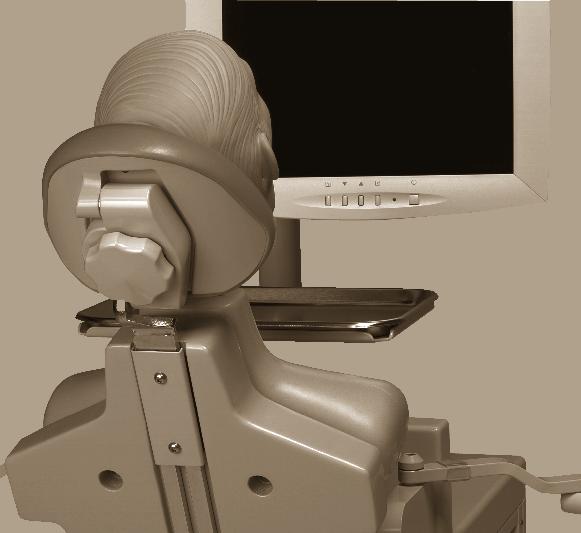
42 Monitor Mount A-DEC STATIONARY SIMULATOR Illustrated Parts Breakdown Monitor Mount The monitor mount is an optional feature. Part No: Figure 16 Monitor Mount Item Part Number Description Mounting plate Screw Pin Washer Bearing Clamp Stationary Simulator Ring Cap Set screw Screw Thrust washer Nut Thrust bearing Clamp cover Screw Screw Arm Rev D 37
43 Monitor Mount A-DEC STATIONARY SIMULATOR Illustrated Parts Breakdown Rev D
44 4 CROSS-SYSTEM FEATURES This section contains information about components and system accessories that pertains to both A-dec Simulator models. C ROSS-SYSTEM FEATURES CONTENTS Cross-System Features Overview A-dec page 41 Handpiece page 44 Manikins page 45 Flow Diagrams Intraoral Light, Standard Control Block page 47 Intraoral Light, Century Plus Control Block page 48 EA-40LT Electric Micromotor page 49 Service/Usage Accessing the Carriage Assembly page 50 Using the EA-40LT Electric Micromotor page 51 Adjustments and Maintenance Making Handpiece Adjustments page 53 Making Syringe Adjustments, Standard Control Block page 55 Making Syringe Adjustments, Century Plus Control Block page 55 Adjusting the A-dec Dual Voltage Intraoral Light Source page 56 Adjusting the Torso Brake (Rotation) page 57 Adjusting the Headrest and Back Assembly page Rev D 39
45 CROSS-SYSTEM FEATURES Illustrated Parts Breakdown Carriage Assembly, Standard Control Block page 60 Carriage Assembly, Century Plus Control Block page 61 Standard Simulator Control Block Assembly, Two Handpiece page 62 Century Plus Simulator Control Block page 63 Master Toggle Century Plus Control Block Only page 65 Century Plus Simulator Control Block Manifold page 64 Handpiece Selector Valve, Two Handpiece page 66 Handpiece Selector Valve, Three Handpiece page 67 Foot Control Wet/Dry Toggle Valve page 68 Foot Control Valve Assembly page 69 Autoclavable Syringe page 70 Autoclavable HVE Standard Assembly, Central Vacuum page 71 Simulator Vacuum Generator Assembly page 72 AVS Valve Assembly page 73 Vacuum Canister/AVS Lid page 74 Torso Brake Parts page 76 Air Filter/Regulator and Water Filter/Regulator page 78 Air-actuated Water Shutoff Valve page 80 Button Valve page 82 Handpiece Holder Arms page 84 Tray Holder page 85 Headrest and Back Assembly page Watt Power Supply page Watt Power Supply page Watt Power Supply page Rev D
46 A-dec Tubing CROSS-SYSTEM FEATURES Overview Overview A-dec Tubing As an option, some simulators come with silicone handpiece tubing. The silicone handpiece tubing uses a European color code for air (blue) and water (green) that differs from the current U.S. standard. Table 7 Silicone Handpiece Tubing Cross Reference Table Color Clear Red Blue Green Function Drive air Exhaust Air coolant Water coolant Table 8 lists functions, descriptions and part numbers. Identify tubing functions by reading the tubing color and tracer markings. Cross-System Features Rev D 41
47 A-dec Tubing CROSS-SYSTEM FEATURES Overview Table 8 A-dec Tubing Identification Function Description Color/Tracer Part Number Chip blower/accessory button Chip blower air - 1/8" OD, brown/ white long dash (10 ) Air coolant signal Air coolant signal air from foot control - 1/8" OD, green/white long dash (10 ) Water coolant signal Water coolant signal air from foot control - 1/8" OD, green/white short dash (10 ) Water Water Supply - 1/8" OD, red (10 ) MADE WITH Unregulated air, master air Continuous, filtered, unregulated air - 1/8" OD from the air filter/regulator to the master On/Off toggle, yellow/ red stripe (10 ) Pilot air Filtered unregulated air controlled by master On/Off toggle - 1/8" OD, yellow/red dash (10 ) Regulated air Continuous, filtered, regulated air - 1/8" OD, yellow (10 ) Rev D
48 A-dec Tubing CROSS-SYSTEM FEATURES Overview Function Description Color/Tracer Part Number Drive air Drive air from foot control to delivery system - 1/4" OD, orange (10 ) Regulated air Supplies regulated air to the foot control - 1/4" OD, yellow (10 ) Water supply Unregulated air Supplies unregulated water from the water supply to the water regulator - 1/4 blue Supplies unregulated air from the shutoff on the Air Manifold to the Air Regulator - 3/8 yellow/black dash (10 ) (10 ) Cross-System Features Rev D 43
49 Surf 6 Handpiece (7') with Terminal Assembly CROSS-SYSTEM FEATURES Handpiece Handpiece Surf 6 Handpiece (7') with Terminal Assembly Figure 17 Handpiece Tubing with Midwest Terminal, 4 hole Figure 20 Handpiece Tubing, fiber optic, 6-pin Vinyl Tubing ; Silicone Tubing Figure 18 Handpiece Tubing, Fiber Optic with Bulb Vinyl Tubing ; Silicone Tubing Figure 21 Cross-section Tubing from the Control Block A B C Vinyl ; Silicone Figure 19 Handpiece Tubing with Borden Terminal, 3 Hole E D (A) Coolant Water; (B) Coolant Air; (C) RIB (Identifier Drive Air Tubing); (D) Exhaust; (E) Drive Air (Ribbed) Vinyl Tubing ; Silicone Tubing Rev D
50 Manikin Part Numbers CROSS-SYSTEM FEATURES Manikins Manikins Figure 23 Frasaco I A-dec Simulator mount and drain kits support the Columbia, Kilgore and Frasaco manikins. Table 9 lists the part numbers. Figure 22 through Figure 26 show the differences. Manikin Part Numbers Table 9 Manikin Part Number Part Number Description Columbia I and Kilgore I, mount and drain kit Frasaco I, mount and drain kit F84J.115 Columbia II, mount kit only Columbia II, drain kit Kilgore II, drain kit Kilgore II, mount kit (supplied with manikin) Frasaco II, mount and drain kit Figure 24 Columbia II Figure 25 Kilgore II Cross-System Features Figure 22 Columbia I and Kilgore I Manikin Drain Assembly Figure 26 Frasaco II Rev D 45
51 CROSS-SYSTEM FEATURES Flow Diagrams Flow Diagrams This section contains illustrated parts breakdowns for items common to both the A-dec Mobile Simulator and the A-dec Stationary Simulator. C ROSS SYSTEM FLOW DIAGRAMS Intraoral Light, Standard Control Block page 47 Intraoral Light, Century Plus Control Block page 48 EA-40LT Electric Micromotor page Rev D
52 Intraoral Light, Standard Control Block CROSS-SYSTEM FEATURES Flow Diagrams Intraoral Light, Standard Control Block The intraoral light is an optional feature. Figure 27 A-dec Dual Voltage Intraoral Light Source and Power Supply Electric Diagram Handpiece Dual Voltage Control (Replace as a Complete Assembly) Voltage Adjustment Controls D E A Cross-System Features B F Control Block Gray Black A B C Gray Green Black Carriage Fiber Optic Wire Assembly Simulator Cable Assembly E D (A) Coolant Water; (B) Coolant Air; (C) RIB (Identifier Drive Air ); (D) Exhaust; (E) Drive Air (Ribbed); (F) Handpiece #2 Drive Air Rev D 47
53 Intraoral Light, Century Plus Control Block CROSS-SYSTEM FEATURES Flow Diagrams Intraoral Light, Century Plus Control Block The intraoral light is an optional feature. H To Selector Valve (See page 66 or page 67) B E G A B C A D F E D (A) Coolant Water; (B) Coolant Air; (C) RIB (Identifier Drive Air ); (D) Exhaust; (E) Drive Air (Ribbed); (F) Fiber Optic Signal; (G) Voltage Adjustment Controls; (H) Second Fiber Optic Position (Optional) Rev D
54 EA-40LT Electric Micromotor CROSS-SYSTEM FEATURES Flow Diagrams EA-40LT Electric Micromotor The EA-40LT electric micromotor is an optional feature. Motor Wire Colors (from left to right) blue black white yellow red orange Motor Coolant (Small Clear) To Handpiece Selector Valve Air Coolant (Blue to Yellow) Control Block Cross-System Features Drive Air (Violet) Tee from Kit Water Coolant (Green to Blue) Pressure Transducer To 24 VAC Power Source Black Black with White Stripe Micromotor Touchpad Foot Control Rev D 49
55 Accessing the Carriage Assembly CROSS-SYSTEM FEATURES Service/Usage Service/Usage This section contains service and usage information for some of the cross-system features. Figure 28 Accessing the Carriage Assembly B C ONTENTS Accessing the Carriage Assembly page 50 Using the EA-40LT Electric Micromotor page 51 C G E Accessing the Carriage Assembly 1. Secure the carriage assembly to the Simulator box using a strong, light rope or a strong, pliable wire. 2. While holding the carriage assembly, remove the six hex screws inside the Simulator box. 3. Slowly tilt the carriage assembly away from the Simulator box. 4. Make sure the rope/wire is installed so that it does not slip when you let go of the carriage assembly. D A D F (A) Carriage Brake Assembly; (B) Rope or Strong, pliable wire; (C) Control Block Cover; (D) Hex Screws; (E) Utilities Bracket; (F) Utilities Cover; (G) Torso Bumper Rev D
56 Using the EA-40LT Electric Micromotor CROSS-SYSTEM FEATURES Service/Usage Using the EA-40LT Electric Micromotor Before Use If your system has the optional micromotor, follow these steps: 1. Check the motor for damage and loose parts before and between uses. 2. Check that air and water coolant spray are set correctly. Install the Motor 1. Position the motor connection tubes with the connection openings on the handpiece. 2. Press the motor and the together until you hear two clicks. 3. If the motor fails to connect, remove it from the. Push back the nut to the stop and repeat steps 1 and Verify that the motor has engaged the securely. The motor and should not separate with a gentle pull. Install the Handpiece WARNING Do not connect or remove the handpiece while the motor is running. Program the Touchpad 1. Press and hold a program key (M1, M2, M3) while adjusting the speed up or down with the + and keys. 2. When the speed value is not changed for more than three seconds, it is stored to that corresponding program key. 3. Press the key to change the motor direction. In clockwise operation, the display is static. In counterclockwise operation, the display flashes. After three seconds, the direction is stored. Changing the motor direction affects all three programs. 4. Change from one program to the other by pressing the program keys, M1, M2 or M3. 5. Press all three program keys at the same time to restore the factory settings. Clean and Disinfect the Motor 1. Wear protective gloves. 2. Remove the handpiece from the motor by pulling the two apart. 3. Carefully wipe the exterior of the micromotor with a soft cloth using only commercially available surface disinfectants or 80% ethyl alcohol. 4. Dry the motor completely. Cross-System Features 1. Push the handpiece onto the motor. If the handpiece is fiber-optic, be sure to line up the notch. 2. Check for a secure hold on the motor. The handpiece should not come off with a gentle pull. Test Run 1. Start the motor by depressing the foot control. 2. If you observe vibrations, unusual noise, heating, smell or leakage, contact A-dec for assistance. Sterilize the Motor 1. Purge the water lines with air. 2. Remove the motor from the by pushing the nut back up to the stop while pulling the motor off the handpiece. 3. Place the motor in sterile goods packaging. 4. Sterilize the motor in a water stream sterilizer with a vacuum for ten minutes at 134 C (273 F). 5. Be sure the motor is dry before removing it from the sterilizer Rev D 51
57 CROSS-SYSTEM FEATURES Adjustments and Maintenance Adjustments and Maintenance This section contains adjustment and maintenance information for some of the cross-system features. C ROSS-SYSTEM ADJUSTMENTS AND M AINTENANCE CONTENTS Making Handpiece Adjustments page 53 Making Syringe Adjustments, Standard Control Block page 55 Making Syringe Adjustments, Century Plus Control Block page 55 Adjusting the A-dec Dual Voltage Intraoral Light Source page 56 Adjusting the Torso Brake (Rotation) page 57 Adjusting the Headrest and Back Assembly page Rev D
58 Making Handpiece Adjustments CROSS-SYSTEM FEATURES Adjustments and Maintenance Making Handpiece Adjustments Figure 29 and Figure 30 shows the handpiece adjustment gauges for the Standard and Century Plus control blocks, and Table 10 defines the icons for these gauges. Figure 29 Handpiece Selections, Standard Control Block B A Table 10 Handpiece Adjustment Icons Icon Description Icon Description Coolant Water Flow Control Coolant Air Flow Control Syringe Air Flow Control Flush F G (A) Coolant Water Flow Control; (B) Coolant Air Flow Control; (C) Drive Air Pressure Flow Controls; (D) Syringe Air Flow Control; (E) Syringe Water Flow Control; (F) High Speed Handpiece; (G) Low Speed Handpiece E D C Drive Air Pressure Flow Controls Syringe Water Flow control High Speed Low Speed Cross-System Features Figure 30 Handpiece Selections, Century Plus Control Block A B C PUSH D (A) Coolant Water Flow Control; (B) Coolant Air Flow Control; (C) Drive Air Pressure Flow Controls; (D) Flush Control Rev D 53
59 Making Handpiece Adjustments CROSS-SYSTEM FEATURES Adjustments and Maintenance Adjust Drive Air Pressure The drive air pressure controls adjusts the drive air pressure to each handpiece. You must adjust the drive air control to meet the handpiece manufacturer s dynamic drive air pressure specification (refer to the documentation that came with your handpiece). To adjust the drive air pressure, use a 3/32" hex key and follow these steps: 1. Attach a handpiece pressure gauge to the handpiece nut, then connect the handpiece to the gauge. 2. Insert the hex key into the drive air control to be adjusted. 3. Move the foot control wet/dry toggle to the Off position (away from the blue dot). 4. Fully depress the foot control disc. 5. Turn the drive air control left until the handpiece is running at slightly above the specified drive air pressure, and then turn the control right until the handpiece runs at the specified drive air pressure. NOTE Do not turn the control left beyond the point where the pressure increases. Doing so allows the control to come completely out of the unit. 6. Repeat steps 1 through 5 for each handpiece. Adjust Coolant Air Flow Use the coolant air flow control and an adjustment key or a 1/8 hex key to adjust the flow of coolant air to the high-speed handpiece. Follow these steps: 1. Insert the key into the coolant air control. 2. Move the wet/dry toggle on the foot control to the Off position (away from the blue dot). 3. Run the handpiece and turn the handpiece coolant air control. A strong flow is recommended. Turn the control right to decrease coolant air flow. Turn it left to increase coolant air flow. Adjust the Coolant Water Flow Use the coolant water flow controls and an adjustment key or a 1/8 hex key to adjust the flow of coolant water to the high speed handpiece. Follow these steps: 1. Insert the key into the coolant water control for the handpiece to be adjusted. 2. Turn the control right until it seats softly. 3. Move the foot control wet/dry toggle to the On position (toward the blue dot). 4. Run the handpiece at medium speed and turn the handpiece coolant water control until a fine mist is visible around the bur. Turn the control right to decrease coolant water flow. Turn it left to increase coolant water flow Rev D
60 Making Syringe Adjustments, Standard Control Block CROSS-SYSTEM FEATURES Adjustments and Maintenance Making Syringe Adjustments, Standard Control Block Adjust Syringe Flow, Standard Control Block Use the syringe flow controls and a 3/32 hex key to adjust water and air flow to the syringe. Follow these steps: 1. Turn the control right to decrease flow. 2. Turn it left to increase flow. NOTE Do not turn the control left beyond the point where the flow increases. Doing so allows the control to come completely out of the unit. Making Syringe Adjustments, Century Plus Control Block Adjust the Syringe Flow, Century Plus Control Block Adjust the syringe air and water flow by turning the appropriate flow control while pressing the air button or water button on the syringe. To adjust them, follow these steps: 1. While facing the flow control, turn the control right to reduce air or water flow. 2. Turn the control left to increase the flow. Adjust the syringe air and water flow to meet the Dental Teams specified requirements. Figure 31 Century Plus Control Block Manifold Cross-System Features A B (A) Syringe Water Flow Control; (B) Syringe Air Flow Control Rev D 55
61 Adjusting the A-dec Dual Voltage Intraoral Light Source CROSS-SYSTEM FEATURES Adjustments and Maintenance Adjusting the A-dec Dual Voltage Intraoral Light Source Adjust the Intraoral Light Source Figure 32 Dual Voltage Intraoral Light Source 1. Set meter to measure Volts DC. 2. Turn the appropriate voltage adjustment control while the handpiece bulb is illuminated. (Refer to your handpiece manufacturer s specified requirements for the correct voltage.) A A-DEC INTRA-ORAL LIGHT SOURCE A B DIMMER SWITCH DUAL VOLTAGE CONTROL P/N POWER OUTPUT ADJUST DISCONNECT DIMMER SWITCH WIRES BEFORE ADJUSTING A B MAX MAX INPUT PWR 24VAC B (A) Dual Voltage Control; (B) Voltage Adjustment Controls Rev D
62 Adjusting the Torso Brake (Rotation) CROSS-SYSTEM FEATURES Adjustments and Maintenance Adjusting the Torso Brake (Rotation) Figure 33 Simulator Torso Brake Assembly and Location Adjust the Torso Brake using a 5/32" and a 3/32" Hex Key 1. Loosen, but do not remove, the torso brake adjustment screw. 2. Loosen, do not remove, the spring tension adjustment screw (so the spring is free). 3. Loosen, do not remove, the setscrew which secures the eccentric pin. To see a complete break down of the parts, refer to Torso Brake Parts on page Rotate the eccentric pin to its loosest position. 5. Turn the spring tension adjustment screw right to remove play on the spring, and then tighten the spring tension adjustment screw two full turns. 6. Depress the torso brake button while rotating the eccentric pin right to the point that any further adjustment causes the clamp to lockup or drag when the assembly is rotated back down. 7. Tighten the setscrew which secures the eccentric pin. 8. Turn the torso brake adjustment screw all the way in until it stops, and then back it out 1-1/4 turns. A B C I H G Cross-System Features Test the Torso Assembly Brake Adjustment The brake assembly should not move with the brake set. The torso assembly should have 14 lb. to 10 lb. drag measured at the ball of the manikin head mount. If the torso assembly moves too freely, increase tension by turning the torso brake adjustment screw left in small increments. If the torso assembly moves with difficulty, decrease tension by turning the torso brake adjustment screw right in small increments. D E F NOTE If necessary, see the Troubleshooting the Torso Brake on page 32 for additional help. A) Set Screws (Manikin Head Mount); (B) Torso Brake Adjustment Screw; (C) Spring Tension Adjustment Screw (for Adjusting Torso Brake Spring Tension); (D) Eccentric Pin; (E) Setscrew (for Securing the Eccentric Pin); (F) Simulator Torso; (G) Torso Brake Assembly; (H) Torso Brake Cylinder; (I) Manikin Head Mount Rev D 57
63 Adjusting the Headrest and Back Assembly CROSS-SYSTEM FEATURES Adjustments and Maintenance Adjusting the Headrest and Back Assembly Figure 34 Headrest Glide Bar Tension Adjustment Adjust the Headrest Glide Bar Tension If your system has the optional headrest and back assembly, you can follow adjust the glide bar tension until the headrest moves freely yet maintains its position. Use a Hex key to adjust the glide bar tension: Turn the screws right to increase friction and hold the headrest more securely. Turn the screws left to decrease friction and allow the headrest to move up and down more freely. Use a hex key to increase or decrease the glide bar tension Rev D
64 Part Identification Symbols CROSS-SYSTEM FEATURES Illustrated Parts Breakdown Illustrated Parts Breakdown C ROSS SYSTEM IPB CONTENTS This section contains illustrated parts breakdowns for items related only to the A-dec Mobile Simulator Model Part Identification Symbols The conventions for the serviceable components tables are designed to identify all parts and kits, including ones that are not for sale. Symbols with reference notes are used. Symbol Definition Indicates that the individual part is not available for sale. (These parts are typically part of a kit or larger assembly that is for sale.) * The part belongs to a kit. No symbol Part is for sale. Carriage Assembly, Standard Control Block page 60 Carriage Assembly, Century Plus Control Block page 61 Standard Simulator Control Block Assembly, Two Handpiece page 62 Century Plus Simulator Control Block page 63 Master Toggle Century Plus Control Block Only page 65 Century Plus Simulator Control Block Manifold page 64 Handpiece Selector Valve, Two Handpiece page 66 Handpiece Selector Valve, Three Handpiece page 67 Foot Control Wet/Dry Toggle Valve page 68 Foot Control Valve Assembly page 69 Autoclavable Syringe page 70 Autoclavable HVE Standard Assembly, Central Vacuum page 71 Simulator Vacuum Generator Assembly page 72 AVS Valve Assembly page 73 Vacuum Canister/AVS Lid page 74 Torso Brake Parts page 76 Air Filter/Regulator and Water Filter/Regulator page 78 Air-actuated Water Shutoff Valve page 80 Button Valve page 82 Handpiece Holder Arms page 84 Tray Holder page 85 Headrest and Back Assembly page Watt Power Supply page Watt Power Supply page Watt Power Supply page 94 Cross-System Features Rev D 59
65 Carriage Assembly, Standard Control Block CROSS-SYSTEM FEATURES Illustrated Parts Breakdown Carriage Assembly, Standard Control Block Figure 35 Carriage Assembly, Standard Control Block Item Part Number Description Carriage brake Clip (Mobile Simulators only) Gas spring Screw Screw Micro valve assembly (self-contained water only) Dual voltage intraoral light source assembly Two-handpiece selector valve Standard control block, two handpiece Cover, controls Rev D
66 Carriage Assembly, Century Plus Control Block CROSS-SYSTEM FEATURES Illustrated Parts Breakdown Carriage Assembly, Century Plus Control Block Figure 36 Carriage Assembly, Century Plus Control Block Item Part Number Description Carriage brake Clip (Mobile Simulators only) Gas spring Screw Screw Micro valve assembly (self-contained water only) Dual voltage intraoral light source assembly Three-handpiece selector valve Block assembly, Century Plus, 2 HP Block assembly, Century Plus, 3 HP Master toggle Cover, controls, upper Cover, controls, lower 1 15 Cross-System Features Rev D 61
67 Standard Simulator Control Block Assembly, Two Handpiece CROSS-SYSTEM FEATURES Illustrated Parts Breakdown Standard Simulator Control Block Assembly, Two Handpiece Part No: Figure 37 Standard Control Block Assembly, Two Handpiece 1 1 Item Part Number Description Flow control screw with O-ring O-ring (package of 10) * Coolant air stem with O-ring * Coolant water stem with O-ring * Diaphragm * Water relay valve assembly * Water valve actuator * Screw, truss head * Screw, socket head * Screw, button head socket * Washer, flat * These parts are included in the Control Block Kit (p/n ) (Install dome side toward diaphragm.) Rev D
68 Century Plus Simulator Control Block CROSS-SYSTEM FEATURES Illustrated Parts Breakdown Century Plus Simulator Control Block Part No: Figure 38 Century Plus Control Bock 9 Item Part Number Description * Drive air flow adjustment screw with O-ring * O-ring, special (package of 10) * Water flow adjustment stem with O-ring * Water valve cartridge, red base * Air bleed cartridge, with O-rings, brass base * Check valve cartridge, with duckbill, blue base * Gasket, molded, side (package of 10) * Diaphragm, top cap,.75 wide x 1.65 long (package of 10) * Nylon washer, flat Cross-System Features 10 & Dry block conversion kit (water valve plug, black base, and check valve plug, black base) * Compression spring,.240 OD x * Control block cap assembly, Century Plus * Actuator, water valve * These parts are included in the Century Plus Control Block Service Kit (p/n ) Rev D 63
69 Century Plus Simulator Control Block Manifold CROSS-SYSTEM FEATURES Illustrated Parts Breakdown Century Plus Simulator Control Block Manifold Part No: Item Part Number Description Syringe Flow Control Barb Spring.21 OD X.71 long O-ring (Package of 10) O-ring (Package of 10) Flush Valve Stem with O rings Coolant Air Stem with O-ring O-ring (Package of 10) Rev D
70 Master Toggle Century Plus Control Block Only CROSS-SYSTEM FEATURES Illustrated Parts Breakdown Master Toggle Century Plus Control Block Only Figure 39 Master Toggle Part No: Item Part Number Description Toggle, surf 4 with pin (fits flush with valve body) Stem with o-rings, 3-way Spring,.300 OD x.400 long * Knurl nut 1 * This part is not included in the Master Toggle assembly (p/n ). Order it separately Cross-System Features Rev D 65
71 Handpiece Selector Valve, Two Handpiece CROSS-SYSTEM FEATURES Illustrated Parts Breakdown Handpiece Selector Valve, Two Handpiece Figure 40 Selector Valve, Two Handpiece Part No: Item Part Number Description Nylon washer (package of 10) Retaining ring E A Spring Ball bearing Barb, 1/8"(package of 10) O-rings (package of 10) B C D (A) Selector Knob; Lube selector knob with Lubriplate lube periodically to prevent sticking; (B) High Speed Handpiece; (C) Low Speed Handpiece (D) Pilot Air Out; (E) Master Air In Rev D
72 Handpiece Selector Valve, Three Handpiece CROSS-SYSTEM FEATURES Illustrated Parts Breakdown Handpiece Selector Valve, Three Handpiece Figure 41 Selector Valve, Three Handpiece Part No: Item Part Number Description Nylon washer (package of 10) Retaining ring Spring Ball bearing Barb, 1/8"(package of 10) O-rings (package of 10) E A B C D Cross-System Features (A) Selector Knob; Lube selector knob with Lubriplate lube periodically to prevent sticking; (B) Handpiece 1; (C) Handpiece 2; (D) Handpiece 3; (E) Pilot Air In Rev D 67
73 Foot Control Wet/Dry Toggle Valve CROSS-SYSTEM FEATURES Illustrated Parts Breakdown Foot Control Wet/Dry Toggle Valve Figure 42 Foot Control Wet/Dry Toggle Valve Part No: Item Part Number Description Foot control toggle valve lever, with pin, pur, Surf Cap spring, wet/dry valve assembly Spring, helical compression,.300 OD x Retainer spring,.600 diameter Holder valve, Surf Pin, dowel,.125 diameter x Setscrew, socket cup point, 6-32 x 3/ way micro valve assembly Rev D
74 Foot Control Valve Assembly CROSS-SYSTEM FEATURES Illustrated Parts Breakdown Foot Control Valve Assembly Part No: Figure 43 Foot Control III Valve Assembly Item Part Number Description Socket head screw * Spring * Spring, helical compression * O-ring (package of 10) Spring cap * Poppet * Spring * Stem with o-rings * Diaphragm (package of 10) Cross-System Features Signal relay valve * FC3 piston * These parts are included in the Foot Control III Service Kit (part number ) Rev D 69
75 Autoclavable Syringe CROSS-SYSTEM FEATURES Illustrated Parts Breakdown Autoclavable Syringe Figure 44 Autoclavable Syringe Part No: Item Part Number Description Nut assembly, syringe, smooth, with O-rings Syringe, Traditional, autoclavable, assembly, with 7' Spacer, syringe nut, with O-ring O-ring, package of Syringe handle, for ambient (cold) water assembly, D-Surf, 7' Screw, 2-56, package of Valve, assembly button, autoclavable, package of Spring, compression, conical, package of Terminal, 2 barb assembly, No-Quick Disconnect O-ring, E,.114 ID x.07 W, package of O-ring, E,.056 ID x.060 W, package of Syringe tip, package of Rev D
76 Autoclavable HVE Standard Assembly, Central Vacuum CROSS-SYSTEM FEATURES Illustrated Parts Breakdown Autoclavable HVE Standard Assembly, Central Vacuum Part No: Figure 45 Autoclavable HVE Assembly 5 Item Part Number Description Body, autoclavable HVE Rotor assembly with O-rings Screen, spring clip, QD, HVE, package of O-ring, E,.489 ID x.070 W, package of O-ring, E,.426 ID x.070 W, package of O-ring,.739 ID x.070 W, package of Tailpiece, QD, short, Surf , 1/2 ID, Tailpiece, standard HVE, with O-ring O-ring,.739 ID x.070 W, package of Standard HVE assembly, over the counter Cross-System Features Rev D 71
77 Simulator Vacuum Generator Assembly CROSS-SYSTEM FEATURES Illustrated Parts Breakdown Simulator Vacuum Generator Assembly Figure 46 Vacuum Generator Assembly (only on units with Simulator AVS) Part No: This assembly is only available on units with the Simulator AVS. 7 Item Part Number Description Screw, socket head Screw, socket head Nylon washer (package of 10) Retainer 1/ Male QD barb 1/ Retainer 1/ Male QD barb 1/4 with O-ring Female QD 1/8, Female QD 1/4, O-ring (package of 10) Body Jet, vacuum Valve cover Diaphragm (package of 10) Air cartridge Optional air cartridge with larger orifice Spacer Stepped piston Rev D
78 AVS Valve Assembly CROSS-SYSTEM FEATURES Illustrated Parts Breakdown AVS Valve Assembly Part No: Figure 47 AVS Valve Assembly (PN ) 4 Item Part Number Description Setscrew, socket cup point (package of 10) (10 ft. length) O-rings (package of 10) O-ring (package of 10) O-ring (package of 10) (10 ft. length) Retainer Rotor AVS body assembly Cross-System Features Rev D 73
79 Vacuum Canister/AVS Lid CROSS-SYSTEM FEATURES Illustrated Parts Breakdown Vacuum Canister/AVS Lid Part No: Drain Valve Assembly Kit ( ) Item Part Number Description Valve stem with O-rings O-rings (package of 10) Drain body Washer Part No: Vacuum Canister Assembly ( ) Part No: Vacuum Canister, AVS ( ) Item Part Number Description O-ring (package of 10) Setscrew (package of 10) O-ring Bottle Mounting block Vacuum canister Nylon washer (package of 10) Barb, 1/8 (package of 10) Item Part Number Description O-ring (package of 10) O-ring (package of 10) Vacuum screen (package of 5) O-ring (package of 10) HVE cap assembly Body, HVE canister Rev D
80 Vacuum Canister/AVS Lid CROSS-SYSTEM FEATURES Illustrated Parts Breakdown Figure 48 Vacuum Canisters Drain Valve Assembly Kit Vacuum Canister, AVS Vacuum Canister, Central Vacuum Cross-System Features 14 Elbow Assembly Rev D 75
81 Torso Brake Parts CROSS-SYSTEM FEATURES Illustrated Parts Breakdown Torso Brake Parts Part No: Item Part Number Description Screw socket head Screw, socket head Nylon washer (package of 10) Hex nut Setscrew Setscrew Retaining ring Pin Spring Lock washer Ball bearing Barb, Restrictor Cylinder end, rotary brake, front Cylinder end, rotary brake, back Piston Diaphragm Modified setscrews Adjuster spring Eccentric Pin Plunger Standoff Link Pin Rev D
82 Torso Brake Parts CROSS-SYSTEM FEATURES Illustrated Parts Breakdown Figure 49 Torso Brake Assembly Cross-System Features Rev D 77
83 Air Filter/Regulator and Water Filter/Regulator CROSS-SYSTEM FEATURES Illustrated Parts Breakdown Air Filter/Regulator and Water Filter/Regulator Common parts to both assemblies: Item Part Number Description Screw, socket head Barb 1/4" (package of 10) O-ring (package of 10) Gasket (package of 10) Filter housing Stud Filter element (package of 6) Socket head screw Washer (package of 10) O-ring (package of 10) Diaphragm (package of 10) Piston with O-ring Barb 1/8 (package of 10) Part No: (Air Filter/Regulator Assembly Only) Item Part Number Description Nut with sleeve, 3/ Barb, 1/ Regulator assembly, air Regulator assembly, preset Regulator assembly, relieving Spring, conical (air regulator only) Adapter, 3/8 poly Body, regulator, white Part No: (Water Filter/Regulator Assembly Only) Item Part Number Description Adapter, 1/4 poly Spring, conical ( for water regulator assembly only) Pipe plug Plug (package of 10) Reducer Regulator assembly, water Nut with sleeve, 1/ Body, regulator, black Rev D
84 Air Filter/Regulator and Water Filter/Regulator CROSS-SYSTEM FEATURES Illustrated Parts Breakdown Figure 50 Air Filter/Regulator and Water Filter/Regulator Air Regulator Assembly ( ) Water Regulator Assembly ( ) Cross-System Features Rev D 79
85 Air-actuated Water Shutoff Valve CROSS-SYSTEM FEATURES Illustrated Parts Breakdown Air-actuated Water Shutoff Valve Part No: (Threaded Shut-off Valve) Item Part Number Description Socket head screw Nipple Nut with sleeve Adapter, 1/4 poly Gasket (package of 10) Regulator assembly, water Part No: (Compression Shut-off Valve) Item Part Number Description Socket head screw Adaptor Nut with sleeve Adaptor Gasket (package of 10) Regulator assembly, water Rev D
86 A-dec Simulators Service Guide Air-actuated Water Shutoff Valve CROSS-SYSTEM FEATURES Illustrated Parts Breakdown Figure 51 Air-actuated Water Shutoff Valves Water Shutoff Valve ( ) Water Shutoff Valve ( ) (Threaded Shut-off Valve) (Compression Shut-off Valve) Cross-System Features Rev D 81
87 Button Valve CROSS-SYSTEM FEATURES Illustrated Parts Breakdown Button Valve Button Valve Prior to November, 2001 Order retrofit upgrade kit F84J.001 for complete assembly. Item Part Number Description Locknut Setscrew Actuator button Plunger way valve Bezel Button Valve After November 2001 Part No: F84J.001* Item Part Number Description Nut, hex Pin, clip Actuator assembly way valve * This assembly does not include the 3-way valve (part number ) Rev D
88 Button Valve After November 2001 CROSS-SYSTEM FEATURES Illustrated Parts Breakdown Figure 52 Button Valve, Brake Actuation, Torso Lift and Rotation Prior to November, 2001* After November, A 4 B 3 2 A 2 C B 5 C 1 Cross-System Features 4 1 (A) Torso Rotation Button; (B) Simulator Torso; (C) Carriage Lift Button *Retrofit kit available. Order F84J.001 upgrade kit, which includes both buttons Rev D 83
89 Handpiece Holder Arms CROSS-SYSTEM FEATURES Illustrated Parts Breakdown Handpiece Holder Arms Part No: (2 Position) and (3 Position) Item Part Number Description Socket head patch screw Tray washer Thrust washer Thrust needle bearing Flat washer Clear Control arm (order with clear installed) 8 - Two position holder bar (order as a special only) 9 - Three position holder bar (order as a special only) Socket cup set screw Socket screw, button head Assistant s holder adaptor Flat washer Arm pin pivot * These parts are included as part of an assembly. Figure 53 Handpiece Holder Arms Rev D
90 Tray Holder CROSS-SYSTEM FEATURES Illustrated Parts Breakdown Tray Holder The tray holder is an optional feature. Part No: Figure 54 Optional Tray Holder 1 Item Part Number Description Tray Holder Hex screw Spring washer Thrust washer Screw Thrust needle bearing Bearing mount Flat washer Tray holder arm Thrust needle bearing Socket head screw Tray washer Cross-System Features Thrust washer Flat washer Flat washer Pivot Rev D 85
91 Headrest and Back Assembly CROSS-SYSTEM FEATURES Illustrated Parts Breakdown Headrest and Back Assembly The headrest is an optional feature. Part No: Figure 55 Optional Headrest and Back Assembly 1 Item Part Number Description Headrest assembly Lock washer (2) Socket screw, button head (2) Chair back Socket head screw (4) Washer (4) Brake plate Brake shoe Spacer (2) Rev D
92 Double Articulating Headrest CROSS-SYSTEM FEATURES Illustrated Parts Breakdown Double Articulating Headrest Part No: Item Part Number Description Screws Glide bar assembly Retaining rings Figure 56 Optional Headrest and Back Assembly 4 Double-Articulating Headrest Assembly 3 Upholstery Options 1 2 Item Part Number Description xx Double-articulating headrest formed upholstery xx Double-articulating headrest plus upholstery Cross-System Features Rev D 87
93 Third Hand Kit CROSS-SYSTEM FEATURES Illustrated Parts Breakdown Third Hand Kit The third hand kit is an optional feature. Part No: Item Part Number Description Flex tube, Washer, plastic Washer, 2.5 OD Washer, thrust Thrust bearing Swivel Spring washer Screw Setscrew Plug Screw Washer, plastic Adaptor Washer, thrust Spring washer Screw Bearing Setscrew Pin Screw Knob Clamp body Rev D
94 Third Hand Kit CROSS-SYSTEM FEATURES Illustrated Parts Breakdown Figure 57 Third Hand Kit Assembly Cross-System Features Rev D 89
95 Third Hand Kit CROSS-SYSTEM FEATURES Illustrated Parts Breakdown Rev D
96 R R 115V A-dec Simulators Service Guide 17 Watt Power Supply CROSS-SYSTEM FEATURES Illustrated Parts Breakdown 17 Watt Power Supply Figure Watt Power Supply, 115V and 230V There are no serviceable parts in the power supply. Replace it with a 25 watt assembly (see page 92). Power supply does not include power cord. Item Part Number Description V power cord BLK BLK/WHT V power cord Simulator wiring harness for Mobile Simulator Voltage Selector Switch Simulator wiring harness for Stationary Simulator 4 17 Watt power supply Part is not for sale. 4 NEWBERG, OR, USA PLUG-IN POWER SUPPLY FOR USE ONLY WITH A-DEC DENTAL EQUIPMENT CAUTION: USE INDOORS ONLY Cross-System Features 17 watt power supply Rev D 91
97 25 Watt Power Supply CROSS-SYSTEM FEATURES Illustrated Parts Breakdown 25 Watt Power Supply Table Watt Power Supply Part Numbers Voltage With Air/Electric Switch Without Air/Electric Switch 100 V V V Table 12 White 6-pin Connector (Dental Light) Pin Voltage Wire Vac Black Vac Gray Table 13 Black 6-pin connector (Handpiece Control) Pin Voltage Wire 1 Ground Green/Yellow 2 0 Vac Black Vac Yellow Rev D
98 25 Watt Power Supply CROSS-SYSTEM FEATURES Illustrated Parts Breakdown Figure Watt Power Supply Cable and Connectors Figure and Vac Power Supply Plumbing (When Air Electric Switch is Provided) D Air Electric Switch (Optional) A Figure Vac Power Supply Plumbing (When Air Electric Switch is Provided) Cross-System Features B D C Air Electric Switches (Optional) (A) Handpiece Control Cable; (B) White 6-pin Connector; (C) Black 6-pin Connector; (D) Air Electric Switch Rev D 93
99 300 Watt Power Supply CROSS-SYSTEM FEATURES Illustrated Parts Breakdown 300 Watt Power Supply Table Watt Power Supply Part Numbers Voltage With Air/Electric Switch Without Air/Electric Switch 100 V l V V Table 15 Black 4-pin Connector (Optional Call Light) Pin Voltage Wire 1 0 Vac Black/White (switched) 3 24 Vac Gray 4 6 Vac Red Table 16 Black 6-pin Connector (Handpiece Control) Pin Voltage Wire 1 Ground Green/Yellow 2 0 Vac Black/White 3 0 Vac Black/White 4 6 Vac Red 5 17 Vac Violet 6 24 Vac Gray Table 17 Red 6-pin Connector (Dental Light) Pin Voltage Wire 1 Ground Green/Yellow 2 0 Vac Black/White 3 15 Vac Green 4 16 Vac Blue 5 17 Vac Violet /12.1 Vac White Table 18 White 6-pin Connector Pin Voltage Wire 1 Ground Green/Yellow 2 0 Vac Black /12.1 Vac White Vac Orange Vac Yellow Vac Yellow Rev D
100 10 A M P 10 A M P 10 A M P 10 A M P 10 A M P 10 A M P A-dec Simulators Service Guide 300 Watt Power Supply CROSS-SYSTEM FEATURES Illustrated Parts Breakdown Figure Watt Power Supplies 100, Vac Power Supply A A B C Air Electric Switch (Optional) B C BLACK BLACK RED B A Vac Power Supply Cross-System Features D WHITE FRONT VIEW C Air Electric Switches (Optional) (A) Black 4-pin Connector (Optional Call Light); (B) Black 6-pin Connector (Handpiece Control); (C) Red 6-pin Connector (Dental Light); (D) White 6-pin Connector (A) Optional Call Light Cable; (B) Handpiece Control Cable; (C) Dental Light Cable Rev D 95
101 300 Watt Power Supply CROSS-SYSTEM FEATURES Illustrated Parts Breakdown Rev D
102 5 TROUBLESHOOTING This section covers troubleshooting information for the Simulator. These tables are not intended to cover every situation, but they do include the most common problems that may be encountered. T ROUBLESHOOTING CONTENTS Troubleshooting the Carriage Assembly page 12 Troubleshooting the Standard Simulator Control Block page 14 Troubleshooting the Century Plus Control Block page 15 Troubleshooting the Foot Control page 24 Troubleshooting the Autoclavable Syringe page 27 Troubleshooting the HVE Valve, Central Vacuum page 28 Troubleshooting the Air Vacuum System (AVS) page 29 Troubleshooting the Torso Brake page 32 Troubleshooting the Mobile Lift Cylinders and Casters page 34 Troubleshooting Rev D 11
103 TROUBLESHOOTING Troubleshooting the Carriage Assembly Troubleshooting the Carriage Assembly Table 7 contains tips and troubleshooting information to assist you in diagnosing the most common carriage assembly problems. This table is not intended to cover every situation, but does include the most common problems that you may encounter. Table 7 Carriage Assembly Troubleshooting Problem Possible Cause Action Simulator carriage is sluggish or halting in lift The air supply is below 80 psi The carriage brake assembly has turned, causing damage to the air supply (clear) Gas spring has lost its charge Check the air supply. If the carriage break assembly has rotated, loosen the two button-head screws and rotate the carriage brake assembly so the air barb is unobstructed. Replace the gas spring Rev D
104 TROUBLESHOOTING Troubleshooting the Carriage Assembly Problem Possible Cause Action Air leaks from the barb The air supply (clear) is damaged Fix the, if it is kinked or cut. The barb is loose Tighten the barb. A B C D E (A) Air Supply ; (B) Barb; (C) Washer; (D) Carriage Brake Assembly; (E) Gas Spring Nylon washer is damaged or worn Replace the nylon washer. Air leaks from the brake cylinder Brake disc O-ring is worn or damaged Replace the brake disc O-ring. Brake disc is worn or damaged Replace the brake disc. Troubleshooting Rev D 13
105 TROUBLESHOOTING Troubleshooting the Standard Simulator Control Block Troubleshooting the Standard Simulator Control Block Table 8 contains tips and troubleshooting information to assist you in diagnosing the most common problems associated with the Standard Simulator control block. This table is not intended to cover every situation, but does include the most common problems that you may encounter. Table 8 Standard Simulator Control Block Troubleshooting Problem Possible Cause Action Air leaks at the syringe air, drive air flow control screws, or coolant air stem Water leaks at the syringe water flow control screw or the coolant water system Water leaks at the control block O-ring is worn or damaged Stem is worn or damaged O-ring is worn or damaged Stem is worn or damaged Control block screws, barbs or washers are loose or damaged Replace the O-ring. Replace the stem. Replace the O-ring. Replace the stem. Follow these steps: 1. Tighten the control block assembly screws. 2. Tighten all barbs and make sure the washers are not damaged. 3. Replace the diaphragm. 4. Replace the stem O-rings. B A C D E F G H (A) Barbs; (B) Assembly Screw; (C) Handpiece #2, Drive Air; (D) Handpiece #1, Drive Air; (E) Air Coolant; (F) Syringe Air; (G) Syringe Water; (H) Water Coolant Rev D
106 TROUBLESHOOTING Troubleshooting the Century Plus Control Block Troubleshooting the Century Plus Control Block Table 9 contains tips and troubleshooting information to assist you in diagnosing the most common carriage assembly problems. This table is not intended to cover every situation, but does include the most common problems that you may encounter. Table 9 Century Plus Control Block Troubleshooting Problem Possible Cause Action Water leaks from the water vent hole (located between the control blocks) Water valve cartridge has failed Replace the water valve cartridge if it is defective. After replacing the cartridge, test the unit. Make sure no water is leaking from the control block. 1. Determine which control block water is leaking water. 2. Exchange the control block water valve cartridge with a known good one. 3. Retest the unit. Make sure no more water is leaking from any point of the control block. If the water valve cartridge is not the problem, go to Coolant water is leaking from one handpiece control block on page 16. A Troubleshooting A D 1 A W D 1 A W D 2 D 1 A W D 2 D 2 (A) Water Vent Hole (as shown in cutout, present on each side of each control block) Rev D 15
107 TROUBLESHOOTING Troubleshooting the Century Plus Control Block Problem Possible Cause Action Coolant water is leaking from one handpiece control block Valve stem or O-ring is worn or defective Water valve cartridge is loose or defective Check valve (flush) cartridge is loose or defective Control block tie bolts are loose or the side gasket may have failed If the water flow adjustment stem is leaking, follow these steps: 1. Remove the valve stem from the block. 2. Inspect the O-ring and the valve stem. 3. Replace all defective parts and test the unit. If the water valve cartridge is leaking, follow these steps: 1. Tighten the cartridge and test the unit. 2. Exchange the cartridge with a known good one and test the unit. 3. Replace the cartridge, if it is defective. If the check valve (flush) cartridge is leaking, follow these steps: 1. Tighten the cartridge and test the unit. 2. Exchange the cartridge with a known good one and test the unit. 3. Replace the cartridge, if it is defective. If the control block bolts are loose, follow these steps: 1. Tighten the tie bolts and test the unit. 2. If these bolts are not loose, the side gasket may have failed. 3. Replace the gasket and retest the unit. A A D 1 W B D 2 A D A W D A W L D W L C D (A) Water Flow Adjustment Stem (on back side); (B) Water Valve Cartridge; (C) Air Bleed Cartridge; (D) Check Valve (Flush) Cartridge; (E) Tie Bolts E L Rev D
108 TROUBLESHOOTING Troubleshooting the Century Plus Control Block Problem Possible Cause Action Coolant water leaks from all handpieces Handpiece flush valve system has failed Follow these steps: 1. Remove the flush valve stem from the control block manifold and inspect the small O-ring and the valve stem. 2. Replace all defective parts and test the unit. A B (A) Small O-ring; (B) Flush Valve Stem Coolant water leaks from one handpiece whether in or out of its holder Coolant water leaks from all wet handpieces when the dry handpiece is used Water valve cartridge has failed Dry block is defective Follow these steps: 1. Exchange the cartridge with a known good one and test the unit. 2. Replace the cartridge if it is defective. 3. Test the unit, and make sure no water is leaking from the control block. If the wet handpieces leak when the coolant water flow control stem is turned completely in to accommodate a dry handpiece, install a Dry Block Conversion Kit (part number ) in the dry handpiece control block. Troubleshooting Rev D 17
109 TROUBLESHOOTING Troubleshooting the Century Plus Control Block Problem Possible Cause Action No coolant water from any of the handpieces Coolant water leaks from all wet handpieces except the one being used Wet/Dry Toggle is off Water is not reaching the control block manifold Control block manifold signal air passage is plugged, to the foot control is crimped, or the foot control relay has failed The Check Valve (Flush) cartridge failed on the handpiece being used Turn the Wet/Dry toggle on the foot control to the On position and test the unit. Press the flush valve stem to see if water is reaching the control block manifold. If no water flows and the unit is not equipped with a Self-contained Water System, check the water filter regulator for proper operation. If the unit is equipped with a Self-contained Water System, follow these steps: 1. Make sure the bottle is filled with water. 2. Verify that the bottle is pressurized by carefully loosening the bottle. A continuous flow of air from the bottle should be heard. If the flow of air stops, air flow to the bottle is restricted. 3. Check the inlet barb on the cap and the to assure they are not plugged. 4. Check the 40 psi pre-regulator on the air filter/regulator assembly for proper operation. Follow these steps: 1. Check to make sure that the coolant water signal is coming from the foot control to the control block manifold. 2. Remove the short dashed green line from the control block manifold and depress the foot control. 3. The control block manifold signal air passage may be plugged. Unplug or replace the manifold. 4. Trace the back to the foot control and check for crimped or failed foot control relay. Remove and replace the Check Valve (Flush) cartridge for the handpiece with a known, good cartridge Rev D
110 TROUBLESHOOTING Troubleshooting the Century Plus Control Block Problem Possible Cause Action No coolant water from one handpiece Coolant water flow control is not properly adjusted Water valve cartridge has failed Refer to Making Handpiece Adjustments on page 53 and page 54, and adjust the coolant water flow. Exchange the cartridge with a known good one and test the unit. A B A D 1 F W D 2 C E D Vent screw on top of the control block is loose or missing Water passage in the block is plugged (A) Vent Screw; (B) Control Block Top Cap Diaphragm; (C) Coolant Water Outlet; (D) Check Valve (Flush) Cartridge; (E) Air Bleed Cartridge; (F) Water Valve Cartridge Tighten or replace the screw and then test the unit. Follow these steps: 1. Turn the unit off, and then remove the water valve cartridge. 2. Momentarily turn the unit on. If the water flows out the bottom of the block from the cartridge position, then the passage between there and the water outlet is plugged. Troubleshooting Rev D 19
111 TROUBLESHOOTING Troubleshooting the Century Plus Control Block Problem Possible Cause Action No drive air at one handpiece Handpiece selector valve is not in the correct position Drive air flow control for the handpiece is not properly adjusted Adjust the selector valve to the correct position and retest the unit. Refer to Making Handpiece Adjustments on page 53 and page 54, and adjust the drive air flow for that handpiece. Holdback signal is pinched or kinked (A) Drive Air Flow Control Stem Follow these steps: 1. Inspect the between the handpiece selector valve and the control block. 2. Inspect the handpiece selector valve for proper operation. 3. Remove any kinks or sharp bends in the and retest the unit. A Rev D
112 TROUBLESHOOTING Troubleshooting the Century Plus Control Block Problem Possible Cause Action Inadequate drive air to all handpieces Air supply to the unit is inadequate Verify that the instrument air supplied to the unit is the minimum required by the handpiece manufacturer, and adjust it, if necessary. The typical requirement for a single high-speed handpiece is 1.5 CFM at 35 psi. The typical requirement for a single low-speed handpiece is 3.0 CFM at 40 psi. Drive air supply is kinked Trace the black dashed orange from the control block manifold back through the unit to the foot control. Straighten any kinks in the and retest the unit. Foot control has failed Check the foot control for proper operation. Check to make sure the outlet barb is unobstructed. If it is obstructed, remove the obstruction, lube the assembly, and retest the unit. Air regulator or pre-regulator failed, or required adjustment Test the air regulator and pre-regulator for proper operation. Replace components, as necessary. A B C Troubleshooting Air filter in the utility module is partially plugged (A) Regulator Assembly; (B) 80 psi Pre-regulator; (C) 40 psi Pre-regulator Replace the air filter, as necessary, and retest the unit. Assemble the filter with the bevelled (stepped) edge toward the manifold Rev D 21
113 TROUBLESHOOTING Troubleshooting the Century Plus Control Block Problem Possible Cause Action Inadequate drive air at one handpiece Drive air flow control for the handpiece is not properly adjusted Refer to Making Handpiece Adjustments on page 53 and page 54, and adjust the drive air flow for that handpiece. Auxiliary drive port (D2) on the control block is leaking A (A) Drive Air Flow Control Stem Tighten the fitting. Replace the washer, if necessary. B A C Control block top cap or diaphragm is leaking Drive air flow control stem is damaged Handpiece exhaust is restricted (A) Control Block Top Cap Diaphragm; (B) Vent Screw; (C) Auxiliary Drive Port (D2) Tighten the top cap screws. If leaking continues, remove the top cap from the control block and inspect the diaphragm for perforations. Replace the diaphragm, if necessary. Remove the drive air flow control stem from the control block. Inspect the O-ring and the stem. Replace any damaged items. Inspect the exhaust and remove any restrictions Rev D
114 TROUBLESHOOTING Troubleshooting the Century Plus Control Block Problem Possible Cause Action No coolant air at one handpiece Inadequate coolant air at all handpieces Inadequate coolant air at one handpiece Handpiece may be plugged or the handpiece may be kinked, pinched, or damaged Coolant air is not properly adjusted Coolant air stem is damaged Foot control is kinked, pinched, or damaged Foot control valve or relay valve in the foot control has failed Handpiece is partially plugged Control block top cap diaphragm has perforated and is leaking Inspect the handpiece to assure that it is not plugged. Inspect the handpiece and be sure that it is not plugged, kinked, or damaged. Replace any damaged handpiece. Refer to Making Handpiece Adjustments on page 53 and page 54, and adjust the coolant water flow. Remove the stem and inspect the stem and the O-ring for damage. Replace all defective parts and test the unit. Relieve any kinks or pinched areas. If the is damaged, it must be replaced. Test and replace components, as needed. Insert a small wire through the air passage in the handpiece terminal to dislodge debris. Replace the diaphragm, if necessary. B A C Troubleshooting All handpieces run while in their holders when the foot control is pressed Unregulated holdback signal air is not present at the control block (A) Control Block Top Cap Diaphragm; (B) Control Block Top Cap; (C) Auxiliary Drive Port (D2) Check the handpiece selector valve for proper operation Rev D 23
115 TROUBLESHOOTING Troubleshooting the Foot Control Troubleshooting the Foot Control Table 10 contains tips and troubleshooting information to assist you in diagnosing the most common foot control problems. This table is not intended to cover every situation, but does include the most common problems that you may encounter. Table 10 Foot Control Troubleshooting Problem Possible Cause Action Audible leakage when foot control is not being used Mounting screws are loose Internal connections are loose Leakage is coming from the exhaust holes on the signal relay valve Parts are defective Leakage is coming from the diaphragm Check to make sure that the mounting screws in the bottom of the base plate to make sure they are tight. If leakage has stopped, then test the unit. Remove the cover and check the internal s for secure connections. Check for leakage from the exhaust holes on the signal relay valve. If there is leakage, do the following: 1. Move the master On/Off toggle to the Off position and bleed the system of air pressure. 2. Inspect the stem and O-rings for debris or defects. 3. Inspect the seat for debris and defects. Replace any defective parts. Lubricate the O-rings, reassemble and test the foot control. Check for leakage round the diaphragm. If there is leakage, tighten the two screws securing the signal relay valve to the foot control valve. If there is still leakage, replace the diaphragm Rev D
116 TROUBLESHOOTING Troubleshooting the Foot Control Problem Possible Cause Action Audible leakage when foot control is in use Diaphragm has failed Check for a failed diaphragm. Tighten the two screws securing the signal relay valve to the foot control valve. If there is still leakage, replace the diaphragm. Leakage is coming from the exhaust holes on the signal relay valve Check for leakage from the exhaust holes on the signal relay valve. If there is leakage, do the following: 1. Move the master On/Off toggle to the Off position and bleed the system of air pressure. 2. Inspect the stem and O-rings for debris or defects. 3. Inspect the seat for debris and defects. Leakage is coming from the exhaust holes on the signal relay valve Check for leakage from the exhaust holes on the signal relay valve. If there is leakage, do the following: 1. Move the master On/Off toggle to the Off position and bleed the system of air pressure. 2. Inspect the stem and O-rings for debris or defects. 3. Inspect the seat for debris and defects. Replace any defective parts. Lubricate the O-rings, reassemble and test the foot control. Parts are defective Inadequate air flow Outlet barb or connections on the signal relay valve are loose Air pressure is low due to obstructions or pinched or parts are defective in the valve assembly Check the outlet barb and on the signal relay valve. Tighten the barb, or replace the. Follow these steps: 1. Check the air pressure. If the air pressure drops by more than 15 psi when the syringe air button and foot control are depressed: Check for pinched foot control. Check for a plugged filter in the air filter/regulator (floor box). Check for an obstructed outlet barb on the signal relay valve. 2. Move the master On/Off toggle to the Off position and bleed the system of air pressure. 3. Remove debris and replace any defective parts in the valve assembly. Lubricate the O-rings, reassemble, and test the foot control. Troubleshooting Rev D 25
117 TROUBLESHOOTING Troubleshooting the Foot Control Problem Possible Cause Action Coolant water continues after releasing the foot control Signal relay valve is sticky or is kinked or plugged Check these in the following order: 1. Check for a sticky signal relay valve. 2. Move the master On/Off toggle to the Off position and bleed the system of air pressure. 3. Remove the signal relay valve, clean it, lube the parts, and reassemble it. 4. Test the foot control. 5. Check for kinked or plugged somewhere between the foot control relay and the control head. Sluggish Foot Control Signal relay valve stem is sticky Follow these steps: 1. Check the valve stem to see if it is sticking. 2. Move the master On/Off toggle to the Off position and bleed the system of air pressure. 3. Remove the signal relay valve, clean it, lube the parts, and reassemble it. 4. Test the foot control Rev D
118 Troubleshooting A-dec Simulators Service Guide TROUBLESHOOTING Troubleshooting the Autoclavable Syringe Troubleshooting the Autoclavable Syringe Table 11 contains tips and troubleshooting information to assist you in diagnosing the most common autoclavable syringe problems. This table is not intended to cover every situation, but does include the most common problems that you may encounter. Table 11 Autoclavable Syringe Troubleshooting Problem Possible Cause Action Air or water is leaking from one of the valve assemblies Air or water is leaking from the syringe tip retainer No air and/or water is issuing from the syringe Valve assembly is worn or damaged Nut assembly is loose or damaged O-rings are worn or damaged Air or water is off or blocked Replace the valve assembly. Check the following: Make sure the syringe nut assembly is properly installed and tightened (use a 5/32 hex key). Replace the syringe nut assembly, if necessary. Replace the O-rings. Follow these steps: 1. Make sure the master On/Off toggle is in the On position. 2. Make sure the air and water supplies are turned on. 3. Check the for kinks or breaks Rev D 27
119 TROUBLESHOOTING Troubleshooting the HVE Valve, Central Vacuum Troubleshooting the HVE Valve, Central Vacuum Table 12 contains tips and troubleshooting information to assist you in diagnosing the most common HVE problems. This table is not intended to cover every situation, but does include the most common problems that you may encounter. Table 12 HVE Troubleshooting Problem Possible Cause Action Water or vacuum is leaking at the HVE Rotary assembly is not installed properly O-rings are worn or damaged Make sure that the rotary assembly is fully inserted into the O-ring groove side of the HVE valve body. Replace the O-rings Rev D
120 Troubleshooting A-dec Simulators Service Guide TROUBLESHOOTING Troubleshooting the Air Vacuum System (AVS) Troubleshooting the Air Vacuum System (AVS) Table 13 contains tips and troubleshooting information to assist you in diagnosing the most common problems with the air vacuum system. This table is not intended to cover every situation, but does include the most common problems that you may encounter. Table 13 Air Vacuum System (AVS) Troubleshooting Problem Possible Cause Action Air leaks at the cap on vacuum generator Air leaks at the vacuum body No vacuum is present, but generator is operating Diaphragm is worn or damaged Vacuum jet O-ring is worn or damaged Screws are loose Air bleed cartridge is worn or damaged Vacuum jet is dirty or damaged Replace the diaphragm. Replace the vacuum jet O-ring. Tighten the screws. Replace the air bleed cartridge. Follow these steps: 1. Clean the vacuum jet. (To access the vacuum generator and muffler tray, remove the screw and slide the tray assembly out from under the Simulator.) 2. If cleaning doesn t fix the problem, replace the vacuum jet Rev D 29
121 TROUBLESHOOTING Troubleshooting the Air Vacuum System (AVS) Problem Possible Cause Action Air is leaking at the vacuum jet Vacuum jet O-ring is worn or damaged Replace the vacuum jet O-ring. Vacuum jet is damaged Replace the vacuum jet. Vacuum generator is noisy Muffler is dirty or damaged Follow these steps: 1. Clean the muffler. (To access the vacuum generator and muffler tray, remove the screw and slide the tray assembly out from under the Simulator.) 2. If cleaning doesn t fix the problem, replace the muffler. Muffler is not properly installed Loosen the cover screw and push muffler towards the generator. Tighten the screw again. A Push Muffler toward Vacuum Generator B (A) Screw; (B) Vacuum Generator Rev D
122 TROUBLESHOOTING Troubleshooting the Air Vacuum System (AVS) Problem Possible Cause Action Vacuum generator does not turn off Holdback air is leaking Follow these steps: 1. Check the AVS handpiece rotor for the O-rings. Replace or lube with silicone, as necessary. A A C B (A) O-ring; (B) Retainer; (C) Rotor 2. Trace the 1/8 holdback tube for leaks at the barbs. Two of the barbs are located on the canister lid and one is on the generator (see figure below). A Holdback air is plugged A (A) Barb Replace the air bleed cartridge in the generator. If the problem returns within three months, it may be necessary to use a larger orifice cartridge (see page 72). Troubleshooting A B (A) Air Bleed Cartridge; (B) Barb Rev D 31
123 TROUBLESHOOTING Troubleshooting the Torso Brake Troubleshooting the Torso Brake Table 14 contains tips and troubleshooting information to assist you in diagnosing the most common problems with torso brake. This table is not intended to cover every situation, but does include the most common problems that you may encounter. Table 14 Torso Brake Troubleshooting Problem Possible Cause Action Torso assembly does not move or is difficult to position Air pressure is off or blocked Follow these steps: 1. Make sure the air compressor is turned on and the pressure is at least 60 psi (80 psi is preferable). If air pressure is acceptable, go to step Make sure the air pressure at the brake is at least 60 psi (80 psi is preferable). Remove the from the brake disc restrictor barb and check the air pressure using a gauge. If the pressure is low, locate the pinched and repair. 3. Check to make sure the restrictor barb is not plugged. If the barb is plugged, replace the restrictor barb. 4. If necessary, adjust the brake; see Adjusting the Torso Brake (Rotation) on page 57. B A C D E (A) Brake Cylinder Cover Screws; (B) Torso Brake Setscrew; (C) Diaphragm; (D) Restrictor Barb; (E) Brake Cover Cylinder Screws Rev D
124 TROUBLESHOOTING Troubleshooting the Torso Brake Problem Possible Cause Action The torso drops The torso assembly is adjustable, but it tends to drop. Torso brake adjustment setscrew is not installed Torso brake adjustment setscrew is not adjusted properly Air pressure is not adjusted properly or blocked or the diaphragm is damaged Air is leaking from the torso assembly is damaged or loose at the restrictor barb Brake cylinder cover is loose Diaphragm is damaged or is incorrectly plumbed at the torso buttons Check to make sure the torso brake setscrew is installed. If not, install the setscrew and follow the brake adjustment instructions on page 57. If the setscrew is installed, check to make sure it is adjusted properly. Rotate to the left to increase tension. Turn the setscrew in small increments; a small turn makes a large change. If this does not work, follow the torso brake adjustment instructions on page 57. Follow these steps: 1. Make sure the air compressor is turned on and the pressure is at least 60 psi (80 psi is preferable). If air pressure is acceptable, go to step Make sure the air pressure at the brake is at least 60 psi (80 psi is preferable). Remove the from the brake disc restrictor barb and check the air pressure using a gauge. If the pressure is low, locate the pinched and repair. 3. Check to make sure the restrictor barb is not plugged. If the barb is plugged, replace the restrictor barb. 4. Press the torso adjustment button and listen for an air leak. If you can hear an air leak, the diaphragm is damaged. Replace the diaphragm. 5. If necessary, adjust the brake; see instructions on page 57. Repair the and/or tighten the restrictor barb. Tighten the brake cylinder cover screws. If air is leaking from the brake cylinder plunger opening, replace the diaphragm. If not, look for incorrectly plumbed at the torso buttons. Troubleshooting Rev D 33
125 TROUBLESHOOTING Troubleshooting the Mobile Lift Cylinders and Casters Troubleshooting the Mobile Lift Cylinders and Casters Table 15 contains tips and troubleshooting information to assist you in diagnosing the most common problems with the mobile lift and cylinder casters. This table is not intended to cover every situation, but does include the most common problems that you may encounter. Table 15 Mobile Lift Cylinders and Casters Troubleshooting Problem Possible Cause Action Unit is difficult to move Casters are worn or damaged Replace one or more casters. Air is leaking at from the barb Barb is loose Tighten the barb. Air (black) is damaged Check the air (black) to the barb is not damaged. If it is, fix or replace it. Nylon washer is worn or damaged Replace the nylon washer. Air is leaking at the lift cylinder Lift seal is worn or damaged Replace the lift seal. A B C (A) Nylon Washers; (B) Barb; (C) Lift Seal Rev D
126 6 DENTAL LIGHTS This section contains information on the dental lights options for the simulators. It provides adjustment and maintenance information, illustrated parts breakdowns, as well as troubleshooting information. Figure and Performer Dental Lights Performer Dental Light D ENTAL LIGHT CONTENTS Adjustments and Maintenance 6300 Dental Light Adjustments page Light Head Rotation page 37 Performer Dental Light Adjustments page 39 Flexarm Adjustments for 6300 and Performer Lights page 41 Maintaining the 6300 and Performer Dental Light page Dental Light Lamp Replacement page 43 Performer Dental Light Lamp Replacement page 44 Illustrated Parts Breakdown 6300 Light Head page 46 Performer Light Head page 47 Troubleshooting the Dental Light page Dental Light Dental Lights Rev D 35
127 DENTAL LIGHTS Adjustments and Maintenance Adjustments and Maintenance This section contains adjustment and maintenance information for the dental lights options. A DJUSTMENTS AND MAINTENANCE CONTENTS 6300 Dental Light Adjustments page Light Head Rotation page 37 Performer Dental Light Adjustments page 39 Flexarm Adjustments for 6300 and Performer Lights page 41 Maintaining the 6300 and Performer Dental Light page Dental Light Lamp Replacement page 43 Performer Dental Light Lamp Replacement page Rev D
128 6300 Dental Light Adjustments DENTAL LIGHTS Adjustments and Maintenance 6300 Dental Light Adjustments Figure 8 Rotation Adjustment The light is preset for proper illumination at 27.6 inches (700 mm) from the black nose piece to the oral cavity. The light has a focal adjustment range between 18" and 31"(460 mm and 790 mm). Focus B A 1. Place a white towel over the chair headrest to represent the oral cavity. 2. Position the light head at the distance normally used when working in the oral cavity (select a distance representative of most procedures). 3. Turn the light ON. 4. Use a large screwdriver to turn the focus adjusting screw until the light, within the borders of the light pattern, is most uniform Light Head Rotation (A) Left/Right Rotation Tension Screw; (B) Diagonal Rotation Tension Screw; (C) Focus Adjusting Screw Figure 9 Left/Right Rotation C The light head needs adjusting if it is difficult to position, moves too easily, or tends to slip out of position. To adjust: Left/Right Rotation (Horizontal) Turn the adjustment screws beginning with the screw at the top of the switch housing: A If the light head moves too easily, or tends to drift out of position, increase the tension by turning the screws right. If the light is difficult to move, loosen the tension by turning the screws left. Dental Lights (A) Top Adjustment Screw Rev D 37
129 6300 Light Head Rotation DENTAL LIGHTS Adjustments and Maintenance Diagonal Rotation (Third Axis) 1. Turn the adjustment screws, beginning with the screw at the bottom of the switch housing: If the light head moves too easily, or tends to drift out of position, increase the tension by turning the screws right. If the light head is difficult to move, loosen the tension by turning the screw left. 2. Tighten the adjustment screw until they are tight to eliminate all movement in the diagonal axis. Up/Down Rotation (Vertical) This adjustment only needs to be made to one side of the light head. To adjust: 1. Loosen the setscrew. 2. Remove the light yoke plug. 3. Use a large flat-blade screwdriver to turn the adjustment screw under the light yoke plug. If the light head moves too easily, or tends to drift out of position, increase the tension by turning the screw right. If the light head is difficult to move, loosen the tension by turning the screw left. 4. Retighten the setscrew, and reinstall the light yoke plug. Figure 10 Diagonal Axis Rotation (A) Bottom Adjustment Screw Figure 11 Up/Down Rotation A B A (A) Setscrew; (B) Light Yoke Plug Rev D
130 Dental Lights A-dec Simulators Service Guide Performer Dental Light Adjustments DENTAL LIGHTS Adjustments and Maintenance Performer Dental Light Adjustments Focus the Light 1. Loosen the focus adjustment screw. Move the bulb socket in or out of the reflector housing until the light is focused. Figure 12 Adjust the Light Head Vertical Tension WARNING To avoid personal injury, be sure that the light has cooled before touching it. 2. Tighten the focus adjustment to fully secure the bulb socket. Adjust the Light Head Vertical Tension 1. Turn Off the dental light. 2. Turn the vertical tension adjustment screw right to increase tension. Turn the adjustment screw left to decrease tension. E A C B D (A) Vertical Tension Adjustment Screw; (B) 5/16 Hex Key; (C) Increase Tension; (D) Decrease Tension; (E) Focus Adjustment Screw Rev D 39
131 Performer Dental Light Adjustments DENTAL LIGHTS Adjustments and Maintenance Adjust the Light Head Horizontal Tension 1. Turn Off the dental light. 2. Turn the horizontal tension adjustment screw right to increase tension. Turn it left to decrease tension. Figure 13 Adjust the Light Head Horizontal Tension B A C (A) Horizontal Tension Adjustment Screw (Use a 5/16 Hex Key); (B) Increase Tension; (C) Decrease Tension Rev D
132 Flexarm Adjustments for 6300 and Performer Lights DENTAL LIGHTS Adjustments and Maintenance Flexarm Adjustments for 6300 and Performer Lights To adjust: 1. Remove the screw and cover from the flexarm. 2. Turn the tension adjustment nut inside the flexarm using a 1/2" open end wrench. 3. Tighten the nut by turning it right, if the flexarm moves too easily, or tends to drift down by itself. 4. Loosen the nut by turning it left, if the arm drifts up. NOTE You must install a travel stop limit kit (P/N ) to limit the upward or downward motion of the flexarm. Figure 14 Flexarm Adjustments Loosen Tighten (A) Adjustment Nut A Dental Lights Rev D 41
133 A-dec Simulators Service Guide Maintaining the 6300 and Performer Dental Light DENTAL LIGHTS Adjustments and Maintenance Maintaining the 6300 and Performer Dental Light Figure 15 Light Shield Cleaning Dental Light Light Shield Cleaning 1. Turn Off the dental light. WARNING To avoid personal injury, be sure that the light has cooled before cleaning it. 2. Remove the light shield. 3. Use a 100% cotton gauze pad or a soft, dry, lint-free cloth to clean the light shield and reflector. If necessary, soak the pad or cloth with water or with a diluted solution of mild dish washing liquid before cleaning. Make certain no residue remains on the surface. C B A (A) Light shield; (B) Reflector; (C) Toggle Do not use abrasives or chlorine (such as household bleach) on the surface of the reflector. These can damage or discolor the reflector surface, impairing the effectiveness. Figure 16 Light Shield Cleaning - Performer Dental Light CAUTION Do not rub heavily, clean the light shield when it is hot, or soak the shield assembly in cleaning solution. Doing so may damage the shield assembly components. Clean the light shield only as instructed. B A (A) Light shield; (B) Reflector Rev D
134 6300 Dental Light Lamp Replacement DENTAL LIGHTS Adjustments and Maintenance 6300 Dental Light Lamp Replacement Figure 17 Remove Lamp from Holder Pull the spare lamp holder from the light head. Remove the lamp from the holder, but do not remove the outer wrapper. Finger oils can affect light performance and severely limit lamp life. If lamp is inadvertently touched, gently clean it with cotton dampened with isopropyl or ethyl alcohol. WARNING To avoid burning fingers, allow the lamp to cool before removing. Never operate the light with the light shield removed. The clear shield minimizes UV light output. The light shield is also protection in the unlikely event that the lamp shatters. A B 1. Turn Off the light, and allow the light to cool. 2. Release the toggles on the light shield and set the shield aside. 3. Use a gauze pad or cloth to protect fingers. Carefully pull the old lamp from its socket and discard. 4. Hold the new lamp in its outer wrapper with the pins facing away, and carefully insert it in the socket. The lamp base is fragile and can break under excess pressure. 5. Remove and discard the outer wrapper, reinstall the light shield, and secure with the toggles. 6. Verify the operation of the light by turning it on and operating it at each intensity setting. CAUTION Use of halogen bulbs other than A-dec P/N (OSRAM HLX 64640, 150W 24V) may result in damage to the bulb socket. (A) Lamp; (B) Holder Figure 18 Insert Lamp (A) New Lamp; (B) Outer Wrapper A B Dental Lights Rev D 43
135 Performer Dental Light Lamp Replacement DENTAL LIGHTS Adjustments and Maintenance Performer Dental Light Lamp Replacement Figure 19 Replacing the Performer Dental Lamp Do not remove the outer wrapper from the new lamp. Finger oils can affect light performance and severely limit lamp life. If lamp is inadvertently touched, gently clean it with cotton dampened with isopropyl or ethyl alcohol. WARNING To avoid burning fingers, allow the lamp to cool before removing. Never operate the light with the light shield removed. The clear shield minimizes UV light output. The light shield is also protection in the unlikely event that the lamp shatters. Install A D C 1. Turn Off the light, and allow the light to cool. 2. Remove the light shield and the bulb cap. 3. Loosen the screws to remove the lamp. Use a gauze pad or cloth to protect your fingers. 4. Disconnect the power wire. 5. Install the new lamp using the outer wrapper, by connecting the power wire and positioning the lamp. Retighten the screws. 6. Discard the outer wrapper. Replace the bulb cap and light shield. 7. Verify the operation of the light by turning it on. (A) Lamp; (B) Bulb Cap; (C) Light Shield; (D) Screws B Rev D
136 Dental Lights A-dec Simulators Service Guide Part Identification Symbols DENTAL LIGHTS Illustrated Parts Breakdown Illustrated Parts Breakdown This section contains illustrated parts breakdowns for dental lights. Part Identification Symbols The conventions for the serviceable components tables are designed to identify all parts and kits, including ones that are not for sale. Symbols with reference notes are used. D ENTAL LIGHT IPB CONTENTS 6300 Light Head page 46 Performer Light Head page 47 Symbol Definition Indicates that the individual part is not available for sale. (These parts are typically part of a kit or larger assembly that is for sale.) * The part belongs to a kit. No symbol Part is for sale Rev D 45
137 6300 Light Head DENTAL LIGHTS Illustrated Parts Breakdown 6300 Light Head Figure Light Head Components Part No: Item Part Number Description Lamp and holder Lamp Holder only Light yoke plug Lamp socket kit Shield bracket assembly, package Pivot stop Intensity switch kit On/off switch kit Switch housing kit Light handle kit Screw Rev D
138 Dental Lights A-dec Simulators Service Guide Performer Light Head DENTAL LIGHTS Illustrated Parts Breakdown Performer Light Head Part No: Figure 21 Performer Light Head Components Item Part Number Description Washer, flat Spring Bearing, thrust Compression bolt Washer, thrust Washer, thrust Toggle switch kit Handle, On/Off switch Bulb socket and insulation volt, 55 Watt halogen bulb Bulb cap assembly Reflector shield Rev D 47
139 DENTAL LIGHTS Troubleshooting the Dental Light Troubleshooting the Dental Light Table 16 contains tips and troubleshooting information to assist in diagnosing the most common dental light problems. This table is not intended to cover every situation, but includes the most common problems that you may encounter. Table 16 Dental Light Troubleshooting Problem Possible Cause Action Light head is loose or difficult to position Flexarm drifts Light intensity is dim, inconsistent, or the color is distorted Unsatisfactory light pattern Light does not function Rotation tension screws are too loose or tight Tension adjustment nut inside the flexarm is too loose or tight Reflector or light shield may be damaged, the intensity switch may be in the wrong position Light is out of focus, reflector or light shield may be damaged No power to the light, defective socket, lamp has failed, or no power to the transformer Adjust the appropriate axis tension Adjust the flexarm counterbalance Follow these steps: 1. Clean the reflector and light shield. 2. Check the intensity switch position. 3. Check the line voltage at the wall. 4. Check the light shield for severe abrasions, and replace if necessary. 5. Check the color of the lamp, replace if discolored. Follow these steps: 1. Focus the light. 2. Check the light shield for severe abrasions, and replace if necessary. 3. Clean the reflector and light shield. Follow these steps: 1. Verify the dental light is connected to a working power source. 2. Ensure all electrical switches are in the On position. 3. Verify the power supply air-electric switch has sufficient air pressure to close. 4. Check for loose connections. 5. Replace the socket, replace the lamp Rev D

140 INDEX Numerics 4810, Mobile Simulator, 1, 4, , Stationary Simulator, 1, 4, dental light, 121, 131, 132 adjusting focus, 123 adjusting the flexarm, 127 adjusting the light head, 123 adjustments and maintenance, 122 cleaning the shield, 128 replacing the lamp, 129 troubleshooting, 134 a A-dec Schools Customer Service, 3 adjustments 6300 dental light, 123 cross-system features, 52 Performer dental light, 125 air filter/regulator, 78 air vacuum system (AVS) lid, 74 mobile, 23 stationary, 34 troubleshooting, 115 vacuum generator assembly, 72 valve assembly, 73 air-actuated water shutoff, 80 autoclavable syringe, 70 adjustments, 55 troubleshooting, 113 AVS, see air vacuum system (AVS) b back and headrest assembly, 86, 87 bench-mounted utilities, mobile simulator, 20 brake, torso, 76 adjustments, 57 troubleshooting, 118 button valve, 82 c carriage assembly Index Rev D 49
Instructions for Use. A-dec 4631 Duo Delivery System and A-dec 4635 Assistant s
 Instructions for Use A-dec 4631 Duo Delivery System and A-dec 4635 Assistant s 85.2643.00 Copyright 2016 A-dec Inc. All rights reserved. A-dec Inc. makes no warranty of any kind with regard to this material,
Assistant s Instrumentation T
 Instructions for Use Assistant s Instrumentation 85.2610.00 T Copyright 2015 A-dec Inc. All rights reserved. A-dec Inc. makes no warranty of any kind with regard to this material, including, but not limited
DECADE 1021 SOLO CHAIR
 Owner's Guide DECADE 1021 SOLO CHAIR 85-2626-00 Warranty A-dec warrants its products against defects in material or workmanship for one year from time of delivery (except for handpieces which have a warranty
Instructions for Use. Cascade 2615 Cart
 Instructions for Use Cascade 2615 Cart 85.0664.00 Copyright 2016 A-dec Inc. All rights reserved. A-dec Inc. makes no warranty of any kind with regard to this material, including, but not limited to, the
A-dec 311, 411, and 511 Dental Chairs Service Reference
 A-dec,, and Dental Chairs Service Reference Copyright Regulatory Information Contents 0 A-dec Inc. All rights reserved. A-dec Inc. makes no warranty of any kind with regard to this material, including,
A-dec 541 Delivery System and 545 Assistant s Instrumentation
 Installation Guide A-dec 541 Delivery System and 545 Assistant s Instrumentation Before You Begin A-dec 545 12 O Clock Assistant s Instrumentation The instructions are the same for installing both the
INSTALLATION INSTRUCTIONS CASCADE 3181 DUO DELIVERY SYSTEM TO PREFERENCECOLLECTION 5580
 R A-DEC INC. 2601 CRESTVIEW DRIVE POST OFFICE BOX 111 NEWBERG, OREGON 97132 USA TELEPHONE (503)-538-9471 DESIGNATED E.U. REPRESENTATIVE: A-DEC DENTAL U.K., LTD. AUSTIN HOUSE 11 LIBERTY WAY ATTLEBOROUGH
A-dec Stools. A-dec 1601 Doctor's Stool A-dec 1621, 1622, and 1626 Assistant's Stools
 Instructions for Use -dec Stools -dec 1601 Doctor's Stool -dec 1621, 1622, and 1626 ssistant's Stools -DEC STOOLS I NSTRUCTIONS FOR USE Copyright 2009 -dec Inc. ll rights reserved. -dec Inc. makes no warranty
A-dec 300 LED Dental Light
 Instructions for Use A-dec 300 LED Dental Light Models 371L 378L A-dec 300 LED Dental Light Instructions for Use Copyright 2018 A-dec Inc. All rights reserved. A-dec Inc. makes no warranty of any kind
Pre-Installation Guide Performer
 Pre-Installation Guide Performer Contents Structural Requirements... 1 Dental Patient Chair Interface Requirement... 1 Utility Requirements... 1 Utility Specifications... 2 Electrical Ratings... 3 Shipping
A-dec O Clock Delivery System
 Installation Guide A-dec 500 12 O Clock Delivery System Before You Begin A-dec 545 12 O Clock Assistant s Instrumentation Before starting the installation: Check with local building and code authorities
DECADE 1021 VAC BACK CHAIR
 Owner's Guide DECADE 1021 VAC BACK CHAIR 85-2625-00 Warranty A-dec warrants its products against defects in material or workmanship for one year from time of delivery (except for handpieces which have
CASCADE CHAIR-MOUNTED HANDPIECE CONTROL WITH CASCADE MASTER SERIES TOUCH PAD
 R A-DEC INC. 2601 CRESTVIEW DRIVE POST OFFICE BOX 111 NEWBERG, OREGON 97132 USA TELEPHONE (503)-538-9471 DESIGNATED E.U. REPRESENTATIVE: A-DEC DENTAL U.K., LTD. AUSTIN HOUSE 11 LIBERTY WAY ATTLEBOROUGH
Radius Cuspidor (for Cascade 1040 or Decade 1011/1021 Chairs)
") INSTALLATION INSTRUCTIONS Radius Cuspidor (for Cascade 1040 or Decade 1011/1021 Chairs) You Will Need: Hex key set Level Large flat head screwdriver Pliers 1/2" and 9/16" wrench Cutters Before Beginning
INSTALLATION INSTRUCTIONS Radius Cuspidor (for Cascade 1040 or Decade 1011/1021 Chairs) You Will Need: Hex key set Level Large flat head screwdriver Pliers 1/2" and 9/16" wrench Cutters Before Beginning
A-dec 351 Assistant s Instrumentation on an A-dec 311/411/511 Dental Chair INSTALLATION GUIDE
 A-dec 351 Assistant s Instrumentation on an A-dec 311/411/511 Dental Chair INSTALLATION GUIDE Contents Before You Begin.......... 2 Install the Rigid Arm....... 3 Connect the Electrical Wires and Data
A-dec Service Guide Edition , 2003
 R Below are the titles of the sections in the 003 edition of the A-dec Service Guide. Click on the title of a section to view it, or click on the bookmarks tab on the left of the window. Both thumbnails
A-dec 500 Delivery Systems
 Instructions for Use A-dec 500 Delivery Systems Models 532, 533, and 542 A-dec 500 Delivery Systems Instructions for Use Copyright 2016 A-dec Inc. All rights reserved. A-dec Inc. makes no warranty of any
A-dec 300 Delivery Systems
 Instructions for Use A-dec 300 Delivery Systems Models 332, 333, 334, 335, and 336 A-dec 300 Delivery Systems Instructions for Use Copyright 2017 A-dec Inc. All rights reserved. A-dec Inc. makes no warranty
Asepsis 21 Delivery Unit
 INSTALLATION INSTRUCTIONS for the Console Mounted TM Asepsis 21 Delivery Unit SECTION I - REQUIREMENTS 1. PHYSICAL REQUIREMENTS... 1 2. ELECTRICAL REQUIREMENTS... 1 3. WATER SUPPLY REQUIREMENTS... 1 4.
A-dec 200 Service Guide Contents
 A-dec 200 Service Guide 1 A-dec 200 Service Guide Contents Overview... 3 Get Support... 3 International Customer Service... 3 Other Sources of Information... 3 Electronic Documentation... 3 A-dec 200 System
INSTRUCTIONS FOR USE. A-dec 311 Dental Chair
 INSTRUCTIONS FOR USE A-dec 311 Dental Chair A-DEC 311 D ENTAL CHAIR I NSTRUCTIONS FOR USE Copyright 2008 A-dec Inc. All rights reserved. A-dec Inc. makes no warranty of any kind with regard to this material,
Loose Components. VetPro 5000 Wall / Cabinet Mount Installation. Applies to Models:
 VetPro 5000 Wall / Cabinet Mount Installation warning Equipment not suitable for use in the presence of a flammable anesthetic mixture. Applies to Models: 8001-001 8001-002 8001-005 8001-006 Loose Components
INTRODUCTION TO SERVICING THE A-dec Handpiece Control Blocks
 INTRODUCTION TO SERVICING THE A-dec Handpiece Control Blocks August, 2017 Presented by Mark Micucci Product Engineer Replacement Parts Industries, Inc. Course Overview The Handpiece Control Block (located
Cascade 3072 Delivery System INSTALLATION GUIDE
 Cascade 3072 Delivery System INSTALLATION GUIDE Getting Started Figure 1. Cascade 3072 Delivery System See the section below that applies to your unit. the Wall............. 1 Preference II 5512 Cabinet......................................
A-dec Dental Lights on an A-dec 300 Base Mount Post INSTALLATION GUIDE
 A-dec Dental Lights on an A-dec 300 Base Mount Post INSTALLATION GUIDE Before You Begin Turn off the power to the system before you begin the installation. DANGER Failure to turn off the power before you
A-dec 570L Dental Light on a Non-DCS System INSTALLATION GUIDE
 A-dec 570L Dental Light on a Non-DCS System INSTALLATION GUIDE Non-DCS LED Dental Light 86.0350.00 Rev B Choose an Installation Guide The manual used to install the light depends on whether the system
A-dec 371L or 571L Dental Light on an A-dec 361, 362, or 363 Support Center INSTALLATION GUIDE
 A-dec 37L or 57L Dental Light on an A-dec 36, 36, or 363 Support Center INSTALLATION GUIDE 37L 57L Before You Begin WARNING Failure to turn off or disconnect the power before you begin this procedure can
The A-dec Difference.
 A-dec 200 The A-dec Difference. The best way to discover what dentists need in a chair and delivery system is to ask. We did. And the A-dec 200 design reflects the way dental teams work, and purposefully
Mounted Instrument Head
 INSTALLATION INSTRUCTIONS for the Asepsis 21 Cabinet TM Mounted Instrument Head SECTION I - REQUIREMENTS 1. PHYSICAL REQUIREMENTS... 1 4. WATER SUPPLY REQUIREMENTS... 1 5. AIR SUPPLY REQUIREMENTS... 1
Wall / Casework Mounted Delivery Systems (Procenter)
") 20 20 0 0 40 40 2 3 0 4 60 60 5 6 7 80 80 00 00 2 3 4 Wall / Casework Mounted Delivery Systems (Procenter) Common Components...004-0859-99 2:00 / FTC Delivery Systems Side Delivery Systems... 004-0886-99
20 20 0 0 40 40 2 3 0 4 60 60 5 6 7 80 80 00 00 2 3 4 Wall / Casework Mounted Delivery Systems (Procenter) Common Components...004-0859-99 2:00 / FTC Delivery Systems Side Delivery Systems... 004-0886-99
forest dental australia affordable excellence + designer friendly
 Component Catalogue 204 table of contents section pages light service items............................................ 2-3 handpiece controls..............................................4 arm systems................................................
Cascade Master Series
 Overview The Cascade Master Series option consists of five components, which control standard chair and delivery system functions. These components include: master touchpad, master 17-watt power supply,
Owner's Guide CASCADE 2671 DUO CART AND CASCADE 3171 DUO WALL-MOUNT
 Owner's Guide CASCADE 2671 DUO CART AND CASCADE 3171 DUO WALL-MOUNT 85.2641.00 ALPHABETICAL EQUIVALENT TO THE NUMERAL OF THE MONTH MANUFACTURED A B C D E F G H I J K L January February March April May
Instructions for Use. Performer. Dental Chair, Delivery System, Assistant s Instrumentation, Support Center with Cuspidor, and Light
 Instructions for Use Performer Dental Chair, Delivery System, Assistant s Instrumentation, Support Center with Cuspidor, and Light Performer Instructions for Use Copyright 2017 A-dec Inc. All rights reserved.
SERVICE PARTS 2013 Q3 A-dec Authorized Dealer Catalog
 SERVICE PARTS 2013 Q3 A-dec Authorized Dealer Catalog Suggested retail prices effective July 2013 Products priced in this catalog are available in the United States and Canada Welcome To The 2013 Genuine
Instructions for Use. A-dec EA-30. Electric Motor System
 Instructions for Use A-dec EA-30 Electric Motor System Copyright 2012 A-dec Inc. All rights reserved. A-dec Inc. makes no warranty of any kind with regard to this material, including, but not limited to,
A-dec 336 Delivery System on an A-dec 411 or 511 Dental Chair INSTALLATION GUIDE
 A-dec 6 Delivery System on an A-dec 4 or 5 Dental Chair INSTALLATION GUIDE Before You Install the 6 Delivery System Install the Rigid Arm A-dec 4 Dental Chair: Follow the instructions for installing the
Owner s Guide PERFORMER III
 Owner s Guide PERFORMER III 85.2638.00 R ALPHABETICAL EQUIVALENT TO THE NUMERAL OF THE MONTH MANUFACTURED A B C D E F G H I J K L January February March April May June July August September October November
Procenter Delivery Mounted on a Free Standing Treatment Console (FTC) Installation
 Installation") Procenter Delivery Mounted on a Free Standing Treatment Console (FTC) Installation Electrical Requirements: 24 VAC, 3.2 Amp 13VAC, 2 Amp Attention These instructions apply to Midmark cabinetry. For other
Procenter Delivery Mounted on a Free Standing Treatment Console (FTC) Installation Electrical Requirements: 24 VAC, 3.2 Amp 13VAC, 2 Amp Attention These instructions apply to Midmark cabinetry. For other
The Belmont Warranty does not cover damage to equipment and upholstery caused by disinfectant solutions. WARRANTY
 Barrier Technique The first choice in the protection of dental equipment should be the use of disposable barrier products. The repeated use of disinfectants on equipment surfaces without the constant removal
Installation Operation Maintenance Troubleshooting Version 1, Oct/09. Palm Beach
 Installation Operation Maintenance Troubleshooting Version 1, Oct/09 1655 Palm Beach Congratulations! All of us at Summit Dental Systems want you to know that your 1655 Palm Beach Cuspidor has been built
1416 Cabinet Unit. Installation Operation Maintenance Troubleshooting Version Dec/17
 Installation Operation Maintenance Troubleshooting Version Dec/17 1416 Cabinet Unit Page 1 of 16 Table of Contents Important Information... 3 Weight & Dimensions... 4 Operator s Instructions... 5 Flow
Procenter Delivery, Console Mounted on an Elevance Chair Installation Guide
 Procenter Delivery, Console Mounted on an Elevance Chair Installation Guide Language of origin: English Equipment Alert Do not remove wraps or packaging from the delivery flex arm assembly until it is
Heavy Duty Miniature Quick-Change Applicator (Side-Feed Type) with Mechanical or Air Feed Systems
 with Mechanical or Air Feed Systems") Heavy Duty Miniature Quick-Change Applicator (Side-Feed Type) with Mechanical or Air Feed Systems Instruction Sheet 408-8040 30 NOV 17 Rev H Ram Assembly Ram Post Locking Screw Stock Drag Drag Release
Heavy Duty Miniature Quick-Change Applicator (Side-Feed Type) with Mechanical or Air Feed Systems Instruction Sheet 408-8040 30 NOV 17 Rev H Ram Assembly Ram Post Locking Screw Stock Drag Drag Release
The A-dec Difference Built for Life
 A-dec 300 The A-dec Difference Built for Life At A-dec, no detail is too small, right down to the bolts that go into our products. That s why we manufacture a large majority of our finished dental equipment
axcs Chair Mounted Unit Installation, Operation and Care Manual
 axcs Chair Mounted Unit Installation, Operation and Care Manual DentalEZ Group 2500 Highway 31 South Bay Minette, AL 36507 Table of Contents Section I Introduction Introduction... 2-3 Specifications...
A-dec 542 Side Delivery System I NSTALLATION GUIDE
 -dec 542 Side Delivery System I NSTLLTION GUIDE This document contains installation instructions for the -dec 542 side delivery system. NOTE Depending on your equipment configuration, some steps in the
INSTRUCTIONS FOR USE CASCADE 2615 CART AND 3175 WALL MOUNT
 INSTRUCTIONS FOR USE CASCADE 2615 CART AND 3175 WALL MOUNT 85.0664.00 R Warranty ALPHABETICAL EQUIVALENT TO THE NUMERAL OF THE MONTH MANUFACTURED A B C D E F G H I J K L January February March April May
The A-dec Difference Built for Life
 A-dec 300 The A-dec Difference Built for Life At A-dec, no detail is too small, right down to the bolts that go into our products. That s why we manufacture a large majority of our finished dental equipment
ISSUED: 14/4/98 CLESTA DTL UNT INST. - 1/11
 ISSUED: 14/4/98 CLESTA DTL UNT INST. - 1/11 SERVICE TRAY SEAT LOWERING SW. PRESET - 3 SWITCH PILOT INDICATOR BACKREST RAISING SW. (OR LAST POSITION) PRESSURE GAUGE BACKREST RECLINING SW. AUTO RETURN SW.
OPERATION and MAINTENANCE INSTRUCTION MANUAL. ADU-12DCE Task Force Deluxe Portable Pneumatic Dental System
 OPERATION and MAINTENANCE INSTRUCTION MANUAL ADU-12DCE Task Force Deluxe Portable Pneumatic Dental System TABLE OF CONTENTS: Package Contents....................i Introduction.........................1
A-dec 2122/2132 Radius System on A-dec 511 Dental Chair I NSTALLATION GUIDE
 -dec 2122/2132 Radius System on -dec 511 ental hair I NSTLLTION GUIE Introduction This document contains instructions for installing an -dec Radius delivery system on an -dec Model 511 chair. This guide
Chair Mounted Unit. Installation, Operation and Care Manual. DentalEZ Group 2500 Highway 31 South Bay Minette, AL 36507
 axcs Basic-Duo Chair Mounted Unit Installation, Operation and Care Manual DentalEZ Group 2500 Highway 31 South Bay Minette, AL 36507 Table of Contents Section I Introduction Introduction... 2 Specifications...3
Flex Work Station Delivery Units Installation Guide
 Flex Work Station Delivery Units Installation Guide Special Tools Level 1/4" Deep Well Socket 3/8" Masonary Bit 9/32" Wood Bit Hammer Drill Remove any packaging from the skid and the floor or wall mount
axcs Magellan CMU Installation, Operation and Care Manual
 axcs Magellan CMU 123456789012 123456789012 123456789012 123456789012 Installation, Operation and Care Manual Table of Contents Section I Introduction Introduction... 2 Specifications... 3 Basic Components...
2006 Dynojet Research, Inc. All Rights Reserved. Spring Applied Air Release (SAAR) Brake Assembly Installation
 Brake Assembly Installation") 2006 Dynojet Research, Inc. All Rights Reserved. This manual is copyrighted by Dynojet Research, Inc., hereafter referred to as Dynojet, and all rights are reserved. This manual, as well as the software
2006 Dynojet Research, Inc. All Rights Reserved. This manual is copyrighted by Dynojet Research, Inc., hereafter referred to as Dynojet, and all rights are reserved. This manual, as well as the software
A-DEC SERVICE PARTS Authorized Dealer Catalog Q2 Edition - View current catalog online
 2018 A-DEC SERVICE PARTS 1.800.547.1883 1.503.538.7478 Within USA/Canada Outside USA/Canada 2018 Authorized Dealer Catalog Q2 Edition - View current catalog online Suggested retail prices effective April
X-Calibur BDS Delivery Systems
 X-Calibur BDS Delivery Systems Table of Contents Page Customer Unit Identification Record 1 General Unit Anatomy 2 Types Of Units 3 Description of Components 5 Control Head Features 5 Cuspidor Features
Simplicity Magellan Unit
 Simplicity Magellan Unit Installation, Operation & Care Manual DentalEZ MAKES YOUR PRACTICE PERFECT Table of Contents Section I Introduction Specifications... 2 Classifications... 2-3 Dimensions... 3 Basic
A-dec LED Dental Light Head on a Demonstration Stand INSTALLATION GUIDE
 A-dec LED Dental Light Head on a Demonstration Stand INSTALLATION GUIDE Introduction Use this installation guide to install an A-dec LED Dental Light Retrofit Kit (28.1924.00 or 28.1925.00) on a custom
COMPONENT WORK SAMPLE 8 Simulated Assembly MAINTENANCE MANUAL. From 1974 to March 15, 2003
 COMPONENT WORK SAMPLE 8 Simulated Assembly MAINTENANCE MANUAL From 1974 to March 15, 2003 Copyright 2008 VALPAR International Corporation P.O. Box 5767 Tucson, Arizona 85703-5767 All rights reserved. No
Simplicity Chair Mounted Unit
 Simplicity Chair Mounted Unit Installation, Operation & Care Manual DentalEZ MAKES YOUR PRACTICE PERFECT Table of Contents Section I Introduction Specifications... 3 Classifications... 3 Dimensions...
The A-dec Difference Built for Life
 A-dec 300 The A-dec Difference Built for Life At A-dec, no detail is too small, right down to the bolts that go into our products. That s why we manufacture a large majority of our finished dental equipment
744A SprAyer Control U S e r M A n U A l
 744A Sprayer Control User MANUAL Table of Contents Product Chapter 1 - Introduction 2 System Configurations... 2 Kit Contents... 4 Control Housing Assembly... 6 Chapter 2 - Installation 7 Mounting Bracket...
Swing Arm Magnifying Lamp
 Owner s Manual & Safety Instructions Save This Manual Keep this manual for the safety warnings and precautions, assembly, operating, inspection, maintenance and cleaning procedures. Write the product s
Installation Instructions: Swing Mounted Units BDS-2575
 Installation Instructions: Swing Mounted Units BDS-2575 X-Calibur Units Installation Instructions for BDS-2575 X-Calibur Dental Units 8-23-10 BDS Swing Mounted Units Installation Time: Approximately 2
Simplicity Hygiene Unit
 Simplicity Hygiene Unit (Magellan Style) Installation, Operation & Care Manual DentalEZ MAKES YOUR PRACTICE PERFECT Table of Contents Section I Introduction Specifications... 3 Classifications... 3 Dimensions...
NEW! SUPPLEMENT I FOR YOUR CATALOG. Visit INTENSITY SWITCH $50.00 POTENTIOMETER $21.
 NEW! SUPPLEMENT I - 2016 FOR YOUR CATALOG Visit WWW.CHAPMAN-HUFFMAN.COM INTENSITY SWITCH 12-620-00 $50.00 Fits ADEC 6300 Wall, Track, Preference and Ceiling Mount dental Lights before serial number D415121
CONTENTS. VIKING PUMP, INC. A Unit of IDEX Corporation Cedar Falls, IA USA SECTION TSM 710.1
 TECHNICAL SERVICE MANUAL industrial heavy duty motor speed pumps SERIES 4076 AND 4176 SIZES hle, ate and ale SECTION TSM 710.1 PAGE 1 of 8 ISSUE B CONTENTS Introduction....................... 1 Safety
Troubleshooting Guide: Elevance Delivery Systems
 Troubleshooting Guide: Elevance Delivery Systems FOR USE BY MIDMARK TRAINED TECHNICIANS Contents Description / Links Troubleshooting Charts ICM Screens Assistant s Unit Instruments (Elevance & European)
Parts Catalog SLICING MACHINES
 Parts Catalog 00N Slicer SLICING MACHINES MODELS: 00N, 0N & 9N -- IMPORTANT! TO EXPEDITE SHIPMENT OF PARTS, ALWAYS SPECIFY MODEL, REV, PART NUMBER, AND SERIAL NUMBER OF SLICER. GLOBE FOOD EQUIPMENT COMPANY
A-dec 200 P RE-INSTALLATION GUIDE
 A-dec 200 P RE-INSTALLATION GUIDE This document contains technical specifications for installing the A-dec 200 equipment line. Contents Structural Requirements...................................................
Table of Contents. Section I Introduction. Section V Operation. Section II Pre-installation. Section VI Care. Section III Installation
 Table of Contents Section I Introduction Classifications... 2 Specifications... 2 Dimensions... 3 Unit Features... 4 Packaging... 5 Section II Pre-installation Utility Service Compartment... 6 Plumbing
ISOBUS Down Force Hydraulics Kinze
 Important Notices Please carefully follow these step-by-step instructions. If you have questions, contact at 515-232-5363 x 1. Direction words (LEFT and RIGHT) are commonly used when describing an installation
PACIFIC Recumbent Height-Adjustable Bath System Parts Breakdown and Assembly Manual
 PACIFIC Recumbent Height-Adjustable Bath System 9700 Parts Breakdown and Assembly Manual Panel 390010-1 Tubs 390011-1 or 390022-1 390748 Revision H 4/1/2014 PENNER PATIENT CARE, INC Box 523 / 101 Grant
Heavy Duty Miniature Quick-Change Applicator (End-Feed Type) with Mechanical or Air-Feed Systems
 with Mechanical or Air-Feed Systems") Heavy Duty Miniature Quick-Change Applicator (End-Feed Type) with Mechanical or Air-Feed Systems Instruction Sheet 408-8039 02 JUN 16 Rev G Ram Post Wire Disc Insulation Disc Insulation Crimper Stripper
Heavy Duty Miniature Quick-Change Applicator (End-Feed Type) with Mechanical or Air-Feed Systems Instruction Sheet 408-8039 02 JUN 16 Rev G Ram Post Wire Disc Insulation Disc Insulation Crimper Stripper
MiTek Machinery Division. Service Bulletin
 MiTek Machinery Division Service Bulletin Machinery Affected: Document: Title: Applies To: Distribution: RoofGlider Press SB198 Redesigned Push Bar Push Bars Manufactured With Gas Spring and Clamp-Style
Evogue Dental Unit IMPORTANT
 Evogue Dental Unit INSTALLATION INSTRUCTIONS IMPORTANT This manual provides installation instructions for the Evogue unit. The instructions contained in this booklet should be thoroughly read and understood
MODEL 5120 Tire Repair Station
 MODEL 5120 Tire Repair Station 00-0049 Installation, Operation & Repair Parts Information Branick Industries, Inc. 4245 Main Avenue P.O. Box 1937 Fargo, North Dakota 58103 REV01182017 P/N: 81-0058G CAUTION
NextGen Cart Delivery Unit
 NextGen Cart Delivery Unit Installation, Operation & Care Manual DentalEZ MAKES YOUR PRACTICE PERFECT Table of Contents Section I Introduction Specifications... 2 Classifications... 2 Dimensions... 3 Features
MODEL G300 BRAKE BLEEDER
 MODEL G300 BRAKE BLEEDER Installation, Operation & Repair Parts Information Branick Industries, Inc. 4245 Main Avenue P.O. Box 1937 Fargo, North Dakota 58103 REV120716 P/N: 81-0035H THIS PAGE INTENTIONALLY
MODEL L/R/EF Sectional Tire Spreader
 MODEL L/R/EF Sectional Tire Spreader Installation, Operation & Repair Parts Information Branick Industries, Inc. 4245 Main Avenue P.O. Box 1937 Fargo, North Dakota 58103 REV08032016 P/N: 81-0195E TABLE
Installation and Operation Manual
 1645 Lemonwood Dr. Santa Paula, CA 93060 USA Toll Free: 1 (800) 253-2363 Tel: 1 (805) 933-9970 rangerproducts.com Ranger Floor Jack Installation and Operation Manual Manual Revision B July 2017 Manual
TECHNICAL SERVICE MANUAL
 Electronic copies of the most current TSM issue can be found on the Viking Pump website at www.vikingpump.com TECHNICAL SERVICE MANUAL industrial heavy duty motor speed pumps SERIES 4076 AND 4176 SIZES
TOYOTA TUNDRA COLD AIR INTAKE Preparation SEQUOIA
 Preparation SEQUOIA 2008 - Part Number: PTR03-34070 (5.7L) PTR03-34072 (4.7L) Kit Contents: 5.7L Item # Quantity Reqd. Description 1 1 Lid: Air Filter 2 1 Inlet Pipe: 5.7L 3 1 Air Filter: TRD Conical 4
Owner s Manual & Safety Instructions
 Owner s Manual & Safety Instructions Save Save This This Manual Keep Keep this this manual manual for for the the safety safety warnings warnings and and precautions, assembly, assembly, operating, inspection,
ETP-5E & ETP-10E ECO-TECH PLUS ELECTRIC CONVECTION STEAMER PARTS AND SERVICE MANUAL
 ETP-5E & ETP-10E ECO-TECH PLUS ELECTRIC CONVECTION STEAMER PARTS AND SERVICE MANUAL EFFECTIVE JANUARY 10, 2018 Superseding All Previous Parts Lists. The Company reserves the right to make substitution
TALCO FIRE SYSTEMS. LSF Start-Up Instructions. 1) IMPORTANT: Inspect the unit for damage. Report any damage to the freight carrier immediately.
 IMPORTANT: Inspect the unit for damage. Report any damage to the freight carrier immediately.") LSF Start-Up Instructions 1) IMPORTANT: Inspect the unit for damage. Report any damage to the freight carrier immediately. 2) PRE-START-UP: Be sure there is water in the pump. Bleed air at all high points
LSF Start-Up Instructions 1) IMPORTANT: Inspect the unit for damage. Report any damage to the freight carrier immediately. 2) PRE-START-UP: Be sure there is water in the pump. Bleed air at all high points
Technical Publications. Winches. Parts Manual. First Edition, First Printing Part No
 Technical Publications Winches Parts Manual First Edition, First Printing Part No. 35503 Genie Industries has endeavored to deliver the highest degree of accuracy possible. However, continuous improvement
Heavy Duty Sprayer Owners Manual Model MS-O
 Heavy Duty Sprayer Owners Manual Model MS-O Table of Contents Warranty 4 Warning 5 Assembly and Preparation 6 Operation 7 Cleaning and Storage 7 Standard Spray Gun & Parts List 8 Trigger Style Spray Gun
Equipment Order Guide
 Equipment Order Guide Effective April 1, 2016 DCI EDGE Equipment Order Guide ORDERING INFORMATION When ordering, please include the following information: DCI requires Doctor, Clinic Name and Address before
IMT Bead Breaker 1000
 Manual Part Number 99903638 IMT Bead Breaker 000 Revised 2050423 Copyright 204 Iowa Mold Tooling Co., Inc. All rights reserved IOWA MOLD TOOLING CO., INC. PO Box 89 Garner, IA 50438 Tel: 64-923-37 FAX:
ATV TRACK KIT. Operator s Manual Installation Instructions Service Instructions Replacement Parts List. Effective Date: October, 2012
 p/n 2258-642 ATV TRACK KIT Operator s Manual Installation Instructions Service Instructions Replacement Parts List Track Assembly Kits (p/n 1436-204) Mounting Assembly Kits (p/n 1436-205) 1436-815) Effective
ASTRO ATS-12 TABBER PARTS MANUAL
 ASTRO ATS-12 TABBER PARTS MANUAL This manual is intended solely for the use and information of Astro Machine Corp., its designated agents, customers, and their employees. The information in this guide
BRAKE SYSTEM Return To Main Table of Contents
 BRAKE SYSTEM Return To Main Table of Contents GENERAL... 2 BRAKE PEDAL... 10 MASTER CYLINDER... 13 BRAKE BOOSTER... 16 BRAKE LINE... 18 PROPORTIONING VALVE... 19 FRONT DISC BRAKE... 20 REAR DRUM BRAKE...
BX88175 Installation Instructions ToadStop II Vacuum Brake System
 BX88175 Installation Instructions ToadStop II Vacuum Brake System Serial No. Customer supplied tools & supplies Utility knife, 12VDC tester, drill & bits: (1/8", 1/4", 5/8 ), ¼ socket drive bit, punch,
Page 1 of 19. Part# /10/2006
 Part# 1002733-01 10/10/2006 This manual contains important information concerning the installation and operation of the gun washers listed above. Read manual thoroughly and keep for future reference INSTRUCTIONS
OnBoard Drum Major Podium
 Assembly and Owner s Manual OnBoard Drum Major Podium CONTENTS CONTENTS................................................................................. 1 SAFETY...................................................................................
GBP784B INSTALLATION TOOL
 GBP784B INSTALLATION TOOL GAGE BILT MADE IN U.S.A. GAGE BILT PRODUCTS CORP. 14500 Barber Drive (586) 771-7664 Warren, Mi 48088 (586) 771-2665 Fax e-mail:solutions@gagebilt.com / www.gagebilt.com TABLE
A-dec 311 Dental Chair and Related Systems
 Pre-Installation Guide A-dec 311 Dental Chair and Related Systems A-dec 311 Dental Chair with 332 Radius -Style Delivery System and 572 Dental Light This document contains technical specifications for