ATV TRACK KIT. Operator s Manual Installation Instructions Service Instructions Replacement Parts List. Effective Date: October, 2012
|
|
|
- Arnold Morton
- 5 years ago
- Views:
Transcription


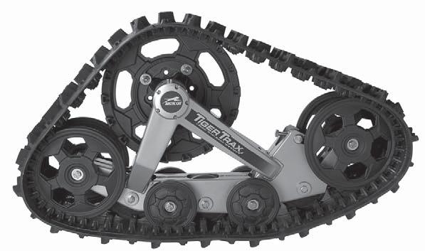
1 p/n ATV TRACK KIT Operator s Manual Installation Instructions Service Instructions Replacement Parts List Track Assembly Kits (p/n ) Mounting Assembly Kits (p/n ) ) Effective Date: October, 2012 SHARE OUR PASSION ṬM
2 LIMITED WARRANTY Arctic Cat Inc. (hereinafter referred to as Arctic Cat) extends a limited warranty on each new Arctic Cat ATV Track Kit sold and initially set up/installed by an authorized Arctic Cat ATV dealer. Arctic Cat warrants that the product is free from defects in materials and workmanship for a period of one (1) year from the date of purchase by the original purchaser. Arctic Cat warrants only the products it manufactures and/or sells and does not warrant that other products will function properly when used with an Arctic Cat ATV or will damage the ATV. Arctic Cat does not assume any liability for incidental or consequential damages. Arctic Cat will repair or replace, at its own option, any parts that are found to be warrantable in material or workmanship. The repair work MUST be done by an authorized Arctic Cat ATV dealer. No transportation charges will be paid by Arctic Cat. Warranty applies only to products which have been properly assembled, adjusted, and operated in accordance with the instructions sent with the product. Warranty does not apply to any product of Arctic Cat that has been subject to alteration, misuse, abuse, improper assembly or installation, normal wear, or normal maintenance. The warranty is validated upon examination of said parts by Arctic Cat or an authorized Arctic Cat ATV dealer. Arctic Cat reserves the right to inspect such parts at its factory for final determination if warranty should apply. In consideration of the foregoing, any implied warranty is limited in duration to the various warranty periods set forth. This warranty gives you specific legal rights, and you may also have other rights which vary from state to state or country to country. Some states do not allow limitations on how long an implied warranty lasts, so the above limitations may not apply to you.

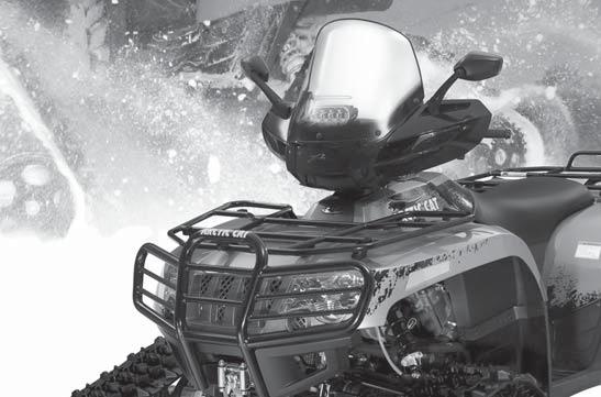
3 NOTE:! The Safety Alert Symbol means ATTENTION! BE ALERT! YOUR SAFETY IS INVOLVED.! WARNING Failure to follow WARNING instructions could result in severe injury or death to the ATV operator, a bystander, or a person inspecting or repairing the ATV.! CAUTION A CAUTION indicates special precautions that must be taken to avoid damage to the ATV and/or the Tracks. A NOTE provides key information to make procedures easier or more clear. Table of Contents Safe Operating Practices... 1 Service Parts... 2 Installation/Adjustment Instructions... 6 Installing New A-Arm Brace... 6 Installing Front Track Kit... 6 Installing Rear Track Kit... 7 Adjusting Front Track... 9 Adjusting Rear Track Installing Snow Deflector Panels Operation Service Maintenance Replacing Track Replacing Sprocket and Main Axle Replacing Wheels (Large) Replacing Wheels (Small External) Replacing Wheels (Small Internal) Replacing Tensioner Pivot Replacing Main Axle Bearing and Seal Replacing Frame Replacing Anti-Rotational Device (Front) Replacing Anti-Rotational Device (Rear) Preparation for Storage Preparation after Storage How to Order Service Parts Owner Registration Safe Operating Practices! WARNING Failure to observe the following safety instructions could result in serious injury and/or death. General Operation NOTE: The track kit raises the center of gravity of the ATV and improves the traction; however, added caution is recommended while operating the vehicle. 1. Read the operating and servicing instructions in this manual carefully. 1 ATV Read the ATV Operator s Manual carefully. 3. Be thoroughly familiar with the controls and the proper use of the ATV with this equipment. 4. Only allow responsible adults, who are familiar with the instructions, to operate the ATV with this equipment. Never allow children to operate the ATV. 5. NEVER CARRY PASSENGERS while operating the ATV with this equipment unless yours is a two-up ATV. 6. When cleaning, repairing, or inspecting, make certain that all moving parts have stopped. Shut off the engine. 7. Exercise extreme caution when crossing over obstacles larger than 30 cm (12 in.). The obstacle may get stuck between the tracks. 8. Beware of hidden and/or underground objects such as logs, branches, and fences. Contact with hidden objects might cause sudden stop of ATV and damage to the tracks. 9. Do not operate the ATV if the tracks have been damaged in any way. Inspect and repair as necessary. 10. Check all fasteners at frequent intervals for tightness to be sure the equipment is in safe operating condition. 11. Maintain or replace safety and instruction labels as necessary.
4 Service Parts Front Track Kit Assembly (p/n ) - Right (p/n ) - Left NOTE: The Qty column reflects the total number of components in both kits. Ref. No. p/n Qty Description Ref. No. p/n Qty Description Track Decal (Right-Side Front) Lock Washer Decal (Left-Side Front) VIN Plaque (Arctic Cat) Decal (Right-Side) Wheel w/o Rubber (5.66-in.) Decal (Left-Side) Wheel (10-in.) Decal (Warning) Wheel w/rubber (5.66-in.) Hex Bolt (1.0 x 20 mm) Sprocket (Arctic Cat) Hex Bolt w/nylon Patch (1.5 x 25 mm) Track Chassis (Right-Side Front) Hex Bolt (1.5 x 100 mm) Track Chassis (Left-Side Front) Hex Bolt (1.75 x 160 mm) Tensioner Pivot Socket Head Cap Screw (0.8 x 16 mm) Wheel Axle (Inside) Socket Head Cap Screw (1.5 x 50 mm) Adjustment Axle (Threaded) Hex Nut Adjustment Axle Hex Nut Bearing Cover Flat Washer Wheel Hub Washer (Fender) Spacer (10.5 mm I.D. x 6 mm) Circlip (Internal) Ball Bearing Seal Ball Bearing Grease Fitting O-Ring Right-Side View 2 ATV-018
5 Rear Track Kit Assembly (p/n ) - Right (p/n ) - Left NOTE: The Qty column reflects the total number of components in both kits. Ref. No. p/n Qty Description Ref. No. p/n Qty Description Track Decal (Right-Side) Lock Washer Decal (Left-Side) Wheel w/o Rubber (5.66-in.) Decal (Warning) Wheel (10-in.) Hex Bolt (1.0 x 20 mm) Wheel w/rubber (5.66-in.) Hex Bolt w/nylon Patch (1.5 x 100 mm) Sprocket (Arctic Cat) Hex Bolt (1.5 x 100 mm) Tensioner Pivot Hex Bolt (1.75 x 160 mm) Wheel Axle (Inside) Socket Head Cap Screw (0.8 x 16 mm) Adjustment Axle (Threaded) Socket Head Cap Screw (1.5 x 50 mm) Adjustment Axle Hex Nut Bearing Cover Hex Nut Wheel Hub Flat Washer Spacer (10.5 mm I.D. x 6 mm) Washer (Fender) Track Chassis (Right-Side - Rear) Circlip (Internal) Track Chassis (Left-Side - Rear) Seal Ball Bearing Grease Fitting Ball Bearing O-Ring Decal (Left-Side Front) Decal (Right-Side Front) Right-Side View ATV-019 3
6 Front Mounting Bracket Kit Assembly (p/n ) - Right (p/n ) - Left NOTE: The Qty column reflects the total number of components in both kits. Ref. No. p/n Qty Description Ref. No. p/n Qty Description Spacer (Thick) - Ball Joint Carriage Bolt (60 mm) Spacer (Thin) - Ball Joint Carriage Bolt (2 3/4 in.) Mount (Right-Side) Hex Nut Mount (Left-Side) Lock Nut (Nylon) Mount Plate (Upper) Lock Nut (Nylon) Plate (Right-Side) - Ball Joint Lock Washer Plate (Left-Side) - Ball Joint Flat Washer Spacer (17 1/2 mm) Ball Joint Frame Bracket * Hex Flange Lock Nut Anti-Rotational Device Bracket * Snow Deflector Panel - Front Hex Bolt (60 mm) * Snow Deflector Panel - Rear Carriage Bolt (50 mm) * Cable Tie * Not shown in illustration Right-Side View ATV
7 Rear Mounting Bracket Kit Assembly (p/n ) - Right (p/n ) - Left NOTE: The Qty column reflects the total number of components in both kits. Ref. No. p/n Qty Description Ref. No. p/n Qty Description Spacer ( mm) Carriage Bolt (60 mm) Bushing Hex Nut Spacer Tube Lock Nut (Nylon) Mount Plate (Upper) Lock Nut (Nylon) Tube (Anti-Rotational) Lock Washer Mount (Right-Side) Flat Washer Mount (Left-Side) Flat Washer (3/4-in. I.D.) Hex Bolt (60 mm) Flat Washer (17 mm I.D.) Right-Side View ATV

8 Installation/Adjustment Instructions NOTE: See an authorized Arctic Cat ATV dealer for the required Clutch Kit (p/n /650/ 700 models) or Clutch Kit (p/n model). 4. Install the front A-arm bracket and the anti-rotational device on the front suspension A-arm using the following procedure. A. Place the mount plate into position on top of the lower A-arm; then install two 60 mm carriage bolts into the top square holes of the plate. Installing New A-Arm Brace (p/n ) NOTE: On Power Steering models, this A-arm brace does not need to be installed. 1. Remove the existing A-arm brace. Retain the cap screw and discard the nut. 2. Remove cap screw from the upper A-arm. Retain the cap screw and discard the nut. 3. Install the new A-Arm Brace. NOTE: The flange faces to the rear of the ATV. ATV-1177A 4. Insert upper suspension cap screw and nut. Tighten hardware removed in steps 1-2 to 35 ft-lb using nut supplied in kit. Installing Front Track Kit NOTE: For a complete illustration and list of components, see page 2 of this manual. This procedure is appropriate for both front wheel kits. 1. Remove the components from the shipping package; then verify that there are no missing or damaged components. See bill of materials for list of parts included in kit. 2. Place the ATV on a flat surface, block the rear wheels (if applicable), and raise the front of the ATV using a support stand.! WARNING Make sure the ATV is solidly supported on the support stand to avoid injury. 3. Remove the front wheel; then remove the front boot guard. Do not discard the boot guard. ATV-1169 B. Insert a 2 3/4-in. carriage bolt into the lower hole of the ball joint plate. C. Place the mount and mount plate into position beneath the lower A-arm; then secure to the mount plate with two 50 mm carriage bolts (inserted from the bottom of the mount), flat washers, and nylon lock nuts. Only fingertighten the nuts at this time. D. Install two 60 mm carriage bolts (inserted from the bottom of the ball joint plate), flat washers, and nylon lock nuts. Only finger-tighten the nuts at this time. E. Install two flat washers and nylon lock nuts onto the two 60 mm carriage bolts (from step A). Only finger-tighten the nuts at this time. F. Tighten all nylon lock nuts to 22 ft-lb using a crisscross pattern. G. Attach the ball joint to the anti-rotational device and lock it in place with the hex nut. 6
, lock washer, flat")


9 ATV-1175 H. Place the thick spacers onto the carriage bolt (from step B); then place the ball joint, thin spacer, and nylon lock nut onto the bolt. Tighten the nylon lock nut to 55 ft-lb. ATV-1171A 7. Rotate the anti-rotational device until the hole in the extremity is aligned with the hole in the frame; then secure with the hex bolt (threads coated with red Loctite #271), lock washer, flat washer, and spacer. Tighten to 31 ft-lb.! CAUTION Do not over-tighten the bolt when installing the device. Some components may deform and may affect security features. 5. At this point, rotate the anti-rotational device toward the center of the ATV to prevent it from interfering when installing the track kit. ATV Install the existing boot guard using existing hardware. Installing Rear Track Kit NOTE: For a complete illustration and list of components, see page 3 of this manual. This procedure is appropriate for both rear wheel kits. ATV Install the front pre-assembled track kit on the front hub; then secure with original lug nuts. Tighten lug nuts to 40 ft-lb. NOTE: For vehicles with aluminum wheels, use nuts from Lug Nut Kit (p/n ).! CAUTION Care must be taken that the front left track kit is installed on the left side and the front right track kit is installed on the right side (see color-coded sticker for proper identification). 1. Remove the components from the shipping package; then verify that there are no missing or damaged components. See bill of material for list of parts included in kit. 2. Place the ATV on a flat surface, block the front wheels (if applicable), and raise the rear of the ATV using a support stand.! WARNING Make sure the ATV is solidly supported on the support stand to avoid injury. 3. Remove the rear wheel; then remove the rear boot guard. Do not discard the boot guard. 7

10 4. Install the rear A-arm bracket and the anti-rotational device on the rear suspension A-arm using the following procedure. A. Place the mount plate into position on top of the lower A-arm; then place the mount beneath the A-arm. ATV-1174 F. Install a 17 mm I.D. flat washer, spacer tube, and bushing onto the anti-rotational tube. Assure the bushing slides over the spacer tube. G. Slide the anti-rotational tube assembly through the hole at the bottom of the mount; then install a bushing, 3/4-in. I.D. flat washer, bushing, 17 mm I.D. flat washer, and nylon lock nut onto the tube. Tighten lock nut securely. ATV-1173 B. Install the two 60 mm carriage bolts into the top square holes of the mount plate through the mount; then secure with flat washers and nylon nuts. Only finger-tighten the nuts at this time. C. Install two 60 mm carriage bolts (inserted from the bottom) through the mount and the mount plate; then secure with the flat washers and nylon nuts. Only finger-tighten the nuts at this time. D. Tighten all nylon nuts to 22 ft-lb using a crisscross pattern. E. Install the hex nut onto the threaded portion of the anti-rotational device tube. ATV-1153B! CAUTION Do not over-tighten the lock nut when installing the device. Some components may deform and may affect security features. 5. Install the rear pre-assembled track kit on the rear hub; then secure with original lug nuts. Tighten lug nuts to 40 ft-lb. NOTE: For vehicles with aluminum wheels, use nuts from Lug Nut Kit (p/n ).! CAUTION Care must be taken that the rear left track kit is installed on the left side and the rear right track kit is installed on the right side (see color-coded sticker for proper identification). 8
, lock washer, flat")
 will raise the rear of the track making turning easier; rotating counterclockwise (screwing out) will lower the rear of the track making")
 between the rear wheel and the ground. ATV-1148 7. Install existing boot guard using existing hardware. Adjusting Front Track NOTE: Adjustments can be made by the ATV owner if qualified to do so.")
11 ATV-1172A 6. Rotate the anti-rotational device until the hole in the extremity is aligned with the hole in the frame; then secure with the hex bolt (threads coated with red Loctite #271), lock washer, flat washer, and spacer. Tighten to 31 ft-lb. ATV-1147A 3. Using a 9/16-in. open end wrench on the notches, rotate the guiding axle to adjust steering effort. NOTE: Rotating the guiding axle clockwise (screwing in) will raise the rear of the track making turning easier; rotating counterclockwise (screwing out) will lower the rear of the track making turning harder. 4. Tighten the jam nut securely. 5. To set vertical distance, use a 17 mm socket and a tape measure. Recommended vertical distance is 18.5 cm (7 3/8 in.) between the rear wheel and the ground. ATV Install existing boot guard using existing hardware. Adjusting Front Track NOTE: Adjustments can be made by the ATV owner if qualified to do so. If the owner does not feel qualified, take the ATV to an authorized Arctic Cat ATV dealer for this service. NOTE: This procedure is appropriate for both front tracks. 1. Place the ATV on a flat surface. 2. To adjust steering effort, use a 3/4-in. open end wrench to loosen the jam nut of the anti-rotational device.! WARNING ATV-1146A If it becomes necessary to unscrew the anti-rotational device ball joint to adjust the track, pay particular attention to the exposed length of the ball joint shaft. If this length exceeds 14 mm (9/16 in.), there will not be enough threads in contact with the sliding rod and loss of control may occur. 9


 when the ATV is on a flat surface. 4.")
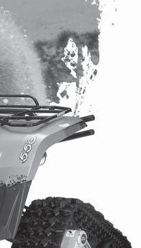
12 Adjusting Rear Track ATV-1145A NOTE: Adjustments can be made by the ATV owner if qualified to do so. If the owner does not feel qualified, take the ATV to an authorized Arctic Cat ATV dealer for this service. ATV-1143A 5. Rotate the adjustment bolt until a track deflection of 19 mm (3/4 in.) at 9 kg (20 lb) force is attained. NOTE: This procedure is appropriate for both rear tracks. 1. Place the ATV on a flat surface. 2. Tighten the 5/8-in. adjustment nuts on both sides of the rubber bushings just to slightly press the rubber bushings against the A-arm bracket. 3. Tighten the 5/8-in. nuts until they jam firmly on the ends of the spacer. Make sure the small wheels are flat on the ground (horizontal). ATV-1142A ATV-1144A NOTE: The nuts must be tightened equally so all of the small wheels stay in contact with the ground (horizontal) when the ATV is on a flat surface. 4. To adjust track tension (deflection), loosen the jam nut on the adjustment pivot.! CAUTION 6. Tighten the jam nut securely. ATV-1176A Do not over-tighten the track or performance loss and/or component damage may occur. Installing Snow Deflector Panels (p/n ) - Front (p/n ) - Rear NOTE: These deflector panels are recommended for use in snow conditions only. 1. Place the front deflector panels in position and secure with cable ties as needed If the ATV does not have rear splash deflectors, install rear deflector panels as shown. Use cable ties as needed.


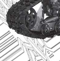
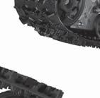
13 Never use solvents to clean the rubber of the tracks. Degradation may occur. Use only water with mild detergent. Periodically apply a good quality grease to the main axles. Remove excess grease from the hub seals. ATV-1149A NOTE: Some ATV s may have rear splash deflectors. In this case, the rear snow deflector panels do not have to be installed. Operation NOTE: Carefully read all items in the Safe Operating Practices section of this manual. An ATV equipped with tracks advances more slowly than when operating on its original wheels; therefore, it moves at a speed approximately 65% that of the speedometer reading.! CAUTION Always have the ATV in 4WD when operating with the track kit. Operating in 2WD will affect performance and may damage the ATV. ATV-1140 NOTE: If the ATV is operated in muddy, wet, or soft terrain conditions. Lubricate the grease points after each use. Periodically lubricate the front anti-rotational device sliding rods: A. Lift the front of the front tracks to compress the anti-rotational device springs. B. Lubricate the sliding rods. Operating in snow conditions may create an ice film on the brake discs. Periodically apply the brakes while operating to remove the ice film. NOTE: See an authorized Arctic Cat ATV dealer for the required Clutch Kit (p/n /700 models) or Clutch Kit (p/n model). Service Maintenance After the initial two hours of operation, check and/or adjust track tension. Daily inspect for loose, damaged, or worn parts and adjust or replace as needed. Periodically check all hardware (especially the wheel lug nuts) to ensure they are tight. Replace any parts that become too worn. Refer to the Service Parts section of this manual for replacement part numbers. Replacing Track ATV-1168 NOTE: This procedure is appropriate for all four tracks. 1. Raise the ATV off the ground using a support stand.! WARNING Make sure the ATV is solidly supported on the support stand to avoid injury. 2. Loosen the jam nut on the tensioner pivot. 11


. 3.")
14 ATV-1167A 3. Loosen the adjustment bolt; then remove the pivot axles. ATV-1142A ATV Rotate the tensioner pivot inward and remove the track. 5. Place the new track in position. NOTE: When installing a track, note the directional arrow. The arrow should be directed toward the front of the ATV when viewing from the top.! CAUTION ATV-1176A Do not over-tighten the track or performance loss and/or component damage may occur. NOTE: After 2-3 hours of operation on a new track, check and/or adjust track tension. Replacing Sprocket and Main Axle NOTE: This procedure is appropriate for all four sprockets and main axles. 1. Raise the ATV off the ground using a support stand.! WARNING Make sure the ATV is solidly supported on the support stand to avoid injury. 2. Remove the track (see Replacing Track sub-section). 3. Remove the bolt and nut securing the anti-rotational device to the frame. ATV Rotate the tensioner pivot outward to its original position. 7. Install the pivot axles; then tighten the adjustment bolt until a track deflection of 19 mm (3/4 in.) at 9 kg (20 lb) force is attained. Tighten the jam nut securely. 12


. Replacing Wheels (Large) ATV-1161 5.")
15 6. Pull the frame assembly straight out and away from the sprocket/main axle assembly. ATV-1162 ATV Remove the four nuts and bolts securing the sprocket to the main axle. Retain all flat washers for assembling purposes. NOTE: At this point, assemble the sprocket/main axle assembly with determined new components. Tighten the new nylon nuts until at least four threads are exposed beyond the nylon portion of the nuts. ATV Using a 3-mm hex key, remove screws securing the bearing cap. Care should be taken not to damage the cap. 8. Press the frame assembly straight onto the sprocket/main axle assembly. 9. Install the axle lock washer; then install the three bolts (threads coated with blue Loctite #242) at the tip of the main axle. Tighten the bolts to 7 ft-lb. NOTE: Lubricate the main axle bearings with a good quality bearing grease. 10. Install the O-ring; then place the bearing cap into position. 11. Using the 3-mm hex key, tighten the bearing cap screws securely. 12. Install the track (see Replacing Track sub-section). Replacing Wheels (Large) ATV Remove the O-ring; then remove the three bolts at the tip of the main axle. Remove the axle lock washer. NOTE: This procedure is appropriate for all four large wheels. 1. Raise the ATV off the ground using a support stand. 2. Remove the tension from the track. 3. Remove the hex bolt and flat washer securing the wheel to the frame. 4. Remove the wheel.! WARNING Make sure the ATV is solidly supported on the support stand to avoid injury. ATV-1160A 13
 at 9 kg (20 lb) force is attained. Tighten the jam nut securely.")

16 5. Place the new wheel into position on the frame; then secure with the hex bolt and flat washer. Tighten to 20 ft-lb. 6. Tighten the track tension adjustment bolt until a track deflection of 19 mm (3/4 in.) at 9 kg (20 lb) force is attained. Tighten the jam nut securely. Replacing Wheels (Small External) NOTE: This procedure is appropriate for all four small external wheels. 1. Raise the ATV off the ground using a support stand.! WARNING Make sure the ATV is solidly supported on the support stand to avoid injury. 2. Remove the tension from the track. 3. Remove the hex bolt and flat washer securing the wheel to the frame. ATV Press downward on the track and slide the wheel down and out. 5. Slide the new wheel into position in the frame; then install the two wheel axles, hex bolt, and nut. Tighten the nut to 20 ft-lb. 6. Tighten the track tension adjustment bolt until a track deflection of 19 mm (3/4 in.) at 9 kg (20 lb) force is attained. Tighten the jam nut securely. Replacing Tensioner Pivot NOTE: This procedure is appropriate for all four tensioner pivots. 1. Raise the ATV off the ground using a support stand.! WARNING Make sure the ATV is solidly supported on the support stand to avoid injury. 4. Remove the wheel. ATV Place the new wheel into position on the frame; then secure with the hex bolt and flat washer. Tighten to 20 ft-lb. 6. Tighten the track tension adjustment bolt until a track deflection of 19 mm (3/4 in.) at 9 kg (20 lb) force is attained. Tighten the jam nut securely. 2. Remove the tension from the track. 3. Remove the large corner wheels. See Replacing Wheels (Large) sub-section. 4. Remove the two nuts and flat washers securing the tensioner pivot to the frame; then remove the pivot. Replacing Wheels (Small Internal) NOTE: This procedure is appropriate for all three small internal wheels. 1. Raise the ATV off the ground using a support stand.! WARNING Make sure the ATV is solidly supported on the support stand to avoid injury. 2. Remove the tension from the track. 3. Remove the hex bolt and nut securing the wheel to the frame; then remove the two wheel axles. ATV Place the new tensioner pivot on the frame and secure with the two nuts and flat washers. 6. Install the large corner wheels. See Replacing Wheels (Large) sub-section. 14

17 7. Tighten the track tension adjustment bolt until a track deflection of 19 mm (3/4 in.) at 9 kg (20 lb) force is attained. Tighten the jam nut securely. Replacing Main Axle Bearing and Seal NOTE: This service can be performed by the ATV owner if qualified to do so. If the owner does not feel qualified, take the ATV to an authorized Arctic Cat ATV dealer for this service. NOTE: This procedure is appropriate for all bearings and seals. 1. Raise the ATV off the ground using a support stand. 2. Remove the tension from the track. 3. Remove the frame assembly away from the sprocket/main axle assembly (see Replacing Sprocket and Main Axle sub-section). 4. Clean excess grease from the bearing housing and hub shaft. 5. Remove the snap ring.! WARNING Make sure the ATV is solidly supported on the support stand to avoid injury. 6. Using an appropriate bearing/seal removing tool, remove the bearing and seal. 7. Using an appropriate bearing installing tool, press the new bearing in place.! CAUTION Assure the bearing is not a sealed-type. If a seal is present, remove it. 8. Using an appropriate seal installing tool, install the new seal making sure the lip of the seal is directed toward the outside. NOTE: Lubricate the main axle bearing with a good quality bearing grease. 11. Tighten the track tension adjustment bolt until a track deflection of 19 mm (3/4 in.) at 9 kg (20 lb) force is attained. Tighten the jam nut securely. Replacing Frame NOTE: This service can be performed by the ATV owner if qualified to do so. If the owner does not feel qualified, take the ATV to an authorized Arctic Cat ATV dealer for this service. NOTE: This procedure is appropriate for all four frames. 1. Raise the ATV off the ground using a support stand.! WARNING Make sure the ATV is solidly supported on the support stand to avoid injury. 2. Remove the tension from the track. 3. Remove the frame assembly away from the sprocket/main axle assembly (see Replacing Sprocket and Main Axle sub-section). 4. Remove all wheels from the frame (see Replacing Wheels sub-sections). 5. Position the new frame; then install all wheels (see Replacing Wheels sub-sections). 6. Install the frame assembly (see Replacing Sprocket and Main Axle sub-section). NOTE: Lubricate the main axle bearing with a good quality bearing grease. 7. Tighten the track tension adjustment bolt until a track deflection of 19 mm (3/4 in.) at 9 kg (20 lb) force is attained. Tighten the jam nut securely. Replacing Anti-Rotational Device (Front) NOTE: This procedure is appropriate for both front devices. 1. Remove the hex bolt, lock washer, flat washer, and spacer securing the devices to the frame. 2. Remove the nut and two ball-joint spacers securing the ball joint to the A-arm bracket. 9. Install the snap ring. ATV-1155A 10. Install the frame assembly (see Replacing Sprocket and Main Axle sub-section). 3. With determined new components, install the ball joint to the A-arm bracket with the two spacers and nut. Tighten the nut to 55 ft-lb. 4. Place the device into position on the frame; then secure with the spacer, flat washer, lock washer, and hex bolt (threads coated with blue Loctite #242). Tighten hex bolt to 31 ft-lb. 15
.")

18 Preparation for Storage 1. Thoroughly clean off any dirt prior to storage. 2. Store on a level location to ensure its stability. 3. Do not put additional weight on the ATV. 4. Store ATV in a clean, dry place. 5. Do not store near a heat source. Preparation after Storage ATV Adjust the front anti-rotational device (see Adjusting Front Track sub-section). Replacing Anti-Rotational Device (Rear) NOTE: This procedure is appropriate for both rear devices. 1. Verify tightening fasteners are secure. 2. Verify that main axles and wheels spin freely. 3. Verify that anti-rotational devices work properly and are adjusted correctly. 4. Verify track tension.! CAUTION If stored for more than four consecutive weeks in a wet place, verify bearings and seals are not damaged. How To Order Service Parts The Service Parts section contains the replacement part numbers of all components of the Track Kits. ATV Remove the self-locking nut from the threaded portion of the anti-rotational device tube. 2. Remove the hex bolt, lock washer, flat washer, and spacer securing the device to the frame. To obtain replacement parts, please contact your Arctic Cat ATV Dealer for service. When ordering parts, please have the following information on hand: Part number you are looking for. Model and serial number of the Track. Quantity required. 3. With determined new components, place the device into position on the frame; then secure with the spacer, flat washer, lock washer, and hex bolt (threads coated in blue Loctite #242). Tighten hex bolt to 31 ft-lb. 4. Adjust the rear anti-rotational device (see Adjusting Rear Track sub-section). 16

19 Owner/Warranty Registration Write the appropriate information in the spaces below. Please keep this information for your own records. Name Address City/Town State/Prov Zip/Postal Code Serial # NOTE: Serial number is located on inside of front right track kit assembly. Date Sold Delivery Checklist: Review the Arctic Cat Limited Warranty with customer. Review with the customer the Safe Operation and Service sections. Review with the customer the periodic lubrication and Maintenance. Review with the customer the daily and periodic inspections. Review with the customer the Service Parts availability. Prior to delivery to the customer, do the following: Record the Serial Number for the Arctic Cat Product. Complete this form which is also available on Cat Tracker and fax form to Make a copy of the registration form for the customer. Give the customer the Operator s Manual and encourage the customer to read the manual. Date Delivered Dealer Signature Customer Signature Date 17
20 NOTES 18
21 NOTES 19
22 NOTES 20
23

24 Printed in U.S.A. Trademarks of Arctic Cat Inc. Thief River Falls, MN p/n
Installation manual. 2 Suspension System. Ford F150 4WD and 2WD. Part # Part # Ford F150 4WD and 2WD
 Installation manual 2 Suspension System 2009-2018 Ford F150 4WD and 2WD Part # 22929 sj12112013rev.03 Part # 22929 2009-2018 Ford F150 4WD and 2WD 2 Suspension System Part # Description Qty. 22909-01 Front
OnBoard Drum Major Podium
 Assembly and Owner s Manual OnBoard Drum Major Podium CONTENTS CONTENTS................................................................................. 1 SAFETY...................................................................................
HIGH RISE POWER ANGLE KIT
 HIGH RISE POWER ANGLE KIT P/N 33-0100 OWNER S MANUAL Application HIGH RISE PUSH TUBE 33-0000 & 34-0000 ATTENTION DEALER: CUSTOMER MUST RECEIVE A COPY OF THIS MANUAL AT THE TIME OF SALE. Before you begin,
CAUTION CAUTION indicates a potentially hazardous situation which, if not avoided, may result in minor or moderate injury.
 Instruction Manual Notes: Page Manual Conventions This manual uses the following symbols to help differentiate between different kinds of information. The safety symbol is used with a key word to alert
Installation manual. Toyota Tundra 4WD & 2WD. 2.5 Suspension kit. Part # Part # Important customer information:
 Installation manual 2007-2016 Toyota Tundra 4WD & 2WD 2.5 Suspension kit Part # 53070 sj11082011rev.03 Part # 53070 2007-2016 Toyota Tundra 4WD & 2WD 2.5 Suspension kit Part # Description Qty. 53070-01
Installation manual. 1.5 front leveling kit. Nissan Titan. Part # Part # Important customer information: Nissan Titan
 Installation manual 1.5 front leveling kit 2004-2015 Nissan Titan Part # 52008 sj071408rev.01 Part # 52008 2004-2015 Nissan Titan 1.5 front leveling kit Part # Description Qty. 52008-01 Front strut spacers
Installation manual Toyota Tundra 4WD & 2WD - 2 front leveling kit Toyota Sequoia 4WD & 2WD - 2 front leveling kit Part # 52070
 Part # 52070 2007-2016 Toyota Tundra 4WD & 2WD 2008-2011 Toyota Sequoia 4WD & 2WD 2 front leveling kit Part # Description Qty. 52070-01 Front strut spacers 2 52070NB Hardware bag 1 52070INST Instruction
Instruction Manual. ATV Plow Tube System
 Instruction Manual ATV Plow Tube System Manual Conventions This manual uses the following symbols to help differentiate between different kinds of information. The safety symbol is used with a key word
Installation manual. 3 suspension system Toyota Tacoma. 4x4 and 2WD PreRunner. Part # Part # Important customer information:
 Installation manual 3 suspension system 2005 2018 Toyota Tacoma 4x4 and 2WD PreRunner Part # 52907 sj11112011rev.05 Part # 52907 2005-2018 Toyota Tacoma 4x4 and 2WD PreRunner 3 suspension system Part #
QUADBOSS UTV STRAIGHT PUSH TUBE OWNER S MANUAL
 PAGE of 6 PART #938 QUADBOSS UTV STRAIGHT PUSH TUBE OWNER S MANUAL This owner s manual covers all aspects of your new push tube including assembly, replacement parts, installation, warranty, and troubleshooting.
2. Remove front wheels.
 1 PARTS DIAGRAM 2 Installation Instructions: (PASSENGER SIDE) 1. Place jack under center of RUV front end and lift until front wheels clear the ground. Be careful to support the RUV properly so that it
Installation manual. 2 front / 1 rear spacer kit Jeep Wrangler JK 2 & 4 door Part # 42005
 Part # 42005 2007-2015 Jeep Wrangler JK 2 & 4 door 2 front / 1 rear spacer kit Parts list: Part # Description Qty. 42005-01 Front coil spring spacers 2 42005-02 Rear coil spring spacers 2 42005INST Instruction
INSTALLATION INSTRUCTIONS
 INSTALLATION INSTRUCTIONS Thank you for purchasing ROLTECTM Electric Hopper Conversion. Agri-Cover, Inc. proudly manufactured this hardware using superior quality materials and workmanship. With proper
IMPORTANT READ ME FIRST
 IMPORTANT READ ME FIRST Thank you for purchasing your Kushlan Mixer. We hope that you will enjoy using it for many years to come. SHOULD YOU REQUIRE ANY SET-UP OR OPERATING ASSISTANCE WITH YOUR PRODUCT,
Owner s Manual. Upper Body Unit. Serial Number Here. Date of Purchase New Hope Road, Raleigh, NC Fusion -
 Revision 1 March 2012 Upper Body Unit Owner s Manual Serial Number Here Date of Purchase www.batcafitness.com 1207 New Hope Road, Raleigh, NC - 919.255.1233 Fusion - www.batcafitness.com 4 Upper Body Station
Instruction Manual. ATV Manual Plow Lift
 Instruction Manual ATV Manual Plow Lift Manual Conventions This manual uses the following symbols to help differentiate between different kinds of information. The safety symbol is used with a key word
Installation manual 3 suspension system Toyota Tacoma 4 x 4 & PreRunner Part # sj rev.03
 Part #: 52904 1995-2004 Toyota Tacoma 4 x 4 & PreRunner 3 suspension system Parts list: Part # Description Qty. 52904-01 Rear brake proportioning valve bracket 1 52907-02 Front pre load spacer 2 52904-03
Installation manual 2 Leveling kit GM x 4. Part # Part # Important customer information: GM x 4
 Installation manual 2 Leveling kit 2007-2008 GM 1500 4 x 4 Part # 12000 sj121007rev.02 Part # 12000 2007-2008 GM 1500 4 x 4 2 leveling system Parts list: Part # Description Qty. 12000-01 Front leveling
Angle Grinder Holder
 Angle Grinder Holder Owner s Manual WARNING: Read carefully and understand all ASSEMBLY AND OPERATION INSTRUCTIONS before operating. Failure to follow the safety rules and other basic safety precautions
Installation manual. Rear traction bars. Ram Ram Part # Part # Important customer information:
 Installation manual Rear traction bars Ram 2500 2003-2013 Ram 3500 2003-2012 Part # 30991 sj12062011rev.01 Part # 30991 2003-2013 Ram 2500, 2003-2012 Ram 3500 Rear traction bars Part # Description Qty.
Airflo MANUFACTURING CO., INC.
 Airflo MANUFACTURING CO., INC. 365 UPPER OAKWOOD AVE, ELMIRA NY 14903 PHONE: 607-733-8284 / FAX: 607-733-0587 OPERATOR & PARTS MANUAL PSV-8L ELECTRIC SPREADER Visit our website at www.air-flo.com Contents
Technical Support Line: (952) Hanover Ave. Lakeville, MN
 Hanover Ave. Lakeville, MN") Technical Support Line: (952) 985-5675 Email: Sales@QA1.net 21730 Hanover Ave. Lakeville, MN 55044 www.qa1.net INSTALLATION INSTRUCTIONS QA1 1967-1979 Mopar A-Body Rear 6 link Conversion System QA1 p/n
Technical Support Line: (952) 985-5675 Email: Sales@QA1.net 21730 Hanover Ave. Lakeville, MN 55044 www.qa1.net INSTALLATION INSTRUCTIONS QA1 1967-1979 Mopar A-Body Rear 6 link Conversion System QA1 p/n
Suspension System RS6582B
 Suspension System RS6582B Tahoe/Yukon READ ALL INSTRUCTIONS THOROUGHLY FROM START TO FINISH BEFORE BEGINNING INSTALLATION IMPORTANT NOTES! WARNING: This suspension system will enhance the off-road performance
IMPORTANT READ ME FIRST
 IMPORTANT READ ME FIRST Thank you for purchasing your Kushlan Mixer. We hope that you will enjoy using it for many years to come. SHOULD YOU REQUIRE ANY SET-UP OR OPERATING ASSISTANCE WITH YOUR PRODUCT,
Installation manual. 3 Suspension Kit Ram WD. Part # Part # Important customer information: 2013 Ram WD
 Installation manual 3 Suspension Kit 2013-2016 Ram 3500 4WD Part # 33118 sj10232013rev.01 Part # 33118 2013 Ram 3500 4WD 3 Suspension Kit Part # Description Qty. 33118-01 Front coil spring spacer 2 33118-02
Installation manual. 3 suspension system Toyota Tacoma. Part # Part # Important customer information: Toyota Tacoma
 Installation manual 3 suspension system 2005 2008 Toyota Tacoma Part # 52907 sj111607rev.02 Part # 52907 2005-2008 Toyota Tacoma 3 suspension system Part # Description Qty. 52907-01 Pre-load spacer 2 52907-02
3 Owner s Manual P E R S O N A L G Y M. Serial Number Here. Date of Purchase
 Revision 5 FEB 2016 P E R S O N A L G Y M Owner s Manual Serial Number Here Date of Purchase www.batcafitness.com 1207 New Hope Road, Raleigh, NC - 919.255.1233 - Fusion www.batcafitness.com 3 Owner s
Installation manual. 3.5 suspension system Chevy / GMC 2500HD / 3500HD With contact overloads Part # 13090
 Part # 13090 2011-2016 Chevy / GMC 2500HD / 3500HD With contact overloads 3.5 suspension system Part # Description Qty. 13085-01 DS & PS Upper control arm 2 13085-02 DS & PS Front upper shock bracket 2
'99-03 CHEVROLET/GMC IFS 4WD 6" SUSPENSION SYSTEM P/N INSTALLATION INSTRUCTIONS
 1/16/04 '99-03 CHEVROLET/GMC IFS 4WD 6" SUSPENSION SYSTEM P/N. 10-41099 INSTALLATION INSTRUCTIONS NOTE: Each Lift Kit and options to Lift Kits are packaged separately. Therefore, installation procedures
Rear Sway Bar for XC90 ( ) 2.5T and T6 ipd mounting kit SBK42
 2.5T and T6 ipd mounting kit SBK42") Dedicated to improving vehicle fun, safety & performance Installation Instructions Rear Sway Bar for XC90 (2003-0) 2.5T and T6 ipd mounting kit SBK2 PI-298 08/06 Thank you for purchasing this anti-sway
Dedicated to improving vehicle fun, safety & performance Installation Instructions Rear Sway Bar for XC90 (2003-0) 2.5T and T6 ipd mounting kit SBK2 PI-298 08/06 Thank you for purchasing this anti-sway
Wheel Horse. 44 Snowthrower. for 5xi Lawn and Garden Tractors. Model No & Up. Operator s Manual
 FORM NO. 8 Rev A Wheel Horse Snowthrower for 5xi Lawn and Garden Tractors Model No. 7966 890050 & Up Operator s Manual IMPORTANT: Read this manual, and your tractor manual, carefully. They contain information
Wheel Horse. 36 Tiller. Model No & Up. Operator s Manual
 FORM NO. 8 9 Rev. A Wheel Horse 6 Tiller for Classic Garden Tractors Model No. 7970 690000 & Up Operator s Manual IMPORTANT: Read this manual carefully. It contains information about your safety and the
Installation manual. Front leveling kit. Part # Part # Important customer information: Ram WD Ram WD
 Installation manual Front leveling kit 2014-2018 Ram 2500 4WD 2013-2018 Ram 3500 4WD Part # 32909 sj10182013rev.02 Part # 32909 2014-2018 Ram 2500 4WD 2013-2018 Ram 3500 4WD Front leveling kit Part # Description
STOP. Broadcast Spreader. Operator's Manual. Model No Safety Assembly Operation Maintenance Parts
 Operator's Manual STOP Broadcast Spreader Model No. 486.2400 DO NOT RETURN TO STORE For Missing Parts or Assembly Questions Call 1-866-56-8388 CAUTION: Before using this product, read this manual and follow
MOTORIZED FOLDING CAMPER WINCH
 OWNER'S MANUAL MOTORIZED FOLDING CAMPER WINCH With 1200lb Lift Capacity The 12 Volt Motorized Folding Camper Winch is used to raise and lower folding campers with the touch of the switch, eliminating hand
Installation Manual. 3 suspension system Toyota Tacoma 4WD & 2WD prerunner. Part # Part # Important customer information:
 Installation Manual 3 suspension system 2005-2018 Toyota Tacoma 4WD & 2WD prerunner Part # 53908 SS03012017 Part # 53908 2007-2018 Toyota Tacoma 4WD & 2WD Prerunner 3 Suspension System (no strut disassembly)
Owner s Manual. Upper Body Unit. Serial Number Here. Date of Purchase New Hope Road, Raleigh, NC Fusion -
 Revision 3 April 2015 Upper Body Unit Owner s Manual Serial Number Here Date of Purchase www.batcafitness.com 1207 New Hope Road, Raleigh, NC - 919.255.1233 Fusion - www.batcafitness.com 4 Upper Body Station
TRACK EXTENSION KIT P/N OWNER S MANUAL ATTENTION DEALER: CUSTOMER MUST RECEIVE A COPY OF THIS MANUAL AT THE TIME OF SALE.
 TRACK EXTENSION KIT P/N 33-0300 OWNER S MANUAL Application PLOW PUSH TUBE NO. 33-0000, 33-0070, 34-0000, 34-0070 ATTENTION DEALER: CUSTOMER MUST RECEIVE A COPY OF THIS MANUAL AT THE TIME OF SALE. Before
Installation manual 3 front / 2 rear suspension system FJ / Runner Part # sj110607rev.03
 Part #: 52000 2007-2014 Toyota FJ / 2003-2009 4Runner 3 front / 2 rear suspension system Parts list: Part # Description Qty. 52907-01 Pre load spacer 2 52907-02 Strut spacer 2 MO3531BK-01 Rear coil spring
Installation manual. 2.5 suspension system. (Except Mega-Cab) Part # Part # Important customer information:
 Part # Part # Important customer information:") Installation manual 2.5 suspension system 2009-2018 Dodge Ram 1500 4WD (Except Mega-Cab) Part # 32102 sj02272013rev.01 Part # 32102 2009-2018 Dodge Ram 1500 4WD (Except Mega-Cab) 2.5 Suspension System
Installation manual 2.5 suspension system 2009-2018 Dodge Ram 1500 4WD (Except Mega-Cab) Part # 32102 sj02272013rev.01 Part # 32102 2009-2018 Dodge Ram 1500 4WD (Except Mega-Cab) 2.5 Suspension System
INSTALLATION INSTRUCTION 88094
 INSTALLATION INSTRUCTION 88094 FOR RANCHO SUSPENSION SYSTEM RS6594B 4WD & 2WD NISSAN TITAN READ ALL INSTRUCTIONS THOROUGHLY FROM START TO FINISH BEFORE BEGINNING INSTALLATION Rev D IMPORTANT NOTES! WARNING:
3 Owner s Manual. Serial Number Here. Date of Purchase New Hope Road, Raleigh, NC Fusion
 Revision 2 Feb. 2013 Owner s Manual Serial Number Here Date of Purchase www.batcafitness.com 1207 New Hope Road, Raleigh, NC - 919.255.1233 - Fusion www.batcafitness.com 3 Owner s Manual Instructions Congratulations
Installation Manual. 3 suspension system Ford F150. Part # Part # Important customer information: Ford F150
 Installation Manual 3 suspension system 2015-2018 Ford F150 Part # 23030 SS08282015 Part # 23030 2015-2018 Ford F150 3 suspension system Part # Description Qty. 23000-01 Driver side upper control arm 1
INSTALLATION INSTRUCTIONS AND OWNER S MANUAL
 INSTALLATION INSTRUCTIONS AND OWNER S MANUAL Thank you for purchasing ADARAC Truck Bed Rack. Agri-Cover, Inc. proudly manufactured this product using superior quality materials and workmanship. With proper
Safety Assembly Operation Service and Adjustment Repair Parts 1602 CORPORATE DRIVE, WARRENSBURG MISSOURI PHONE FAX
 swisherinc.com OWNER S MANUAL MODEL NO. 12019 12019A Blade Mount Adaptor IMPORTANT Read and follow all Safety Precautions and Instructions before operating this equipment. REV 11-283 Safety Assembly Operation
Commercial Pro Plow Combo, 50" ATV
 CHANGING YOUR LANDSCAPE SINCE 1945 swisherinc.com OWNER S MANUAL 19975 Starting Serial #: L215-001001 Commercial Pro Plow Combo, 50" ATV IMPORTANT Read and follow all Safety Precautions and Instructions
INSTALLATION MANUAL TOYOTA TUNDRA 5 SUSPENSION SYSTEM PART # 55905
 PART NUMBER : 55905 1999 2003 TOYOTA TUNDRA 5 SUSPENSION SYSTEM PARTS LIST: Part # Description Qty. 55900-01 Driver Side Spindle 1 55900-02 Passenger Side Spindle 1 55905-03 Rear brake proportioning valve
4331 EUCALYPTUS AVE. CHINO, CA PHONE FAX
 www.fabtechmotorsports.com 4331 EUCALYPTUS AVE. CHINO, CA. 91710 PHONE 909-597-7800 FAX 909-597-7185 FTS22115 Dirt Logic 2.25 Dual Steering Stabilizer System 2000-2004 Ford F250 & F350 4WD PARTS LIST:
m WARNING: READ ALL m WARNING: This unit can be dangerous! Careless or m DANGER: Risk of cut. Keep hands and feet away IMPORTANT! Safety Instructions
 16-Inch Manual Reel Mower with Catcher Model No. MJ500M Form No. SJ-MJ500M-880E A Division of Snow Joe, LLC IMPORTANT! Safety Instructions m WARNING: READ ALL INSTRUCTIONS BEFORE USE. m WARNING: This unit
203 TRANSFER CASE CONVERSION
 203 TRANSFER CASE CONVERSION PN:501 OUR FOUR TRANSFER CASE WEDGES REPLACE THE SPIDER GEARS AND CONNECT THE PLANETARY GEAR AND REAR OUTPUT SHAFT MAKING ONE UNIT. SIMILAR IN DESIGN & FUNCTION TO THE BEST
HF4145 FOLDING MULTI-POSITION WORKOUT BENCH
 HF4145 FOLDING MULTI-POSITION WORKOUT BENCH Note: Both Serial Number and Model Number are Required when Ordering Parts RECORD SERIAL NUMBER HERE CATALOG NUMBER 0406-001 Customer Service (800) 548-5438
(877) MON-FRI 7AM-5PM PST OR WEBSITE: ReadyLIFT.COM **Please retain this document in your vehicle at all times**
 MON-FRI 7AM-5PM PST OR WEBSITE: ReadyLIFT.COM **Please retain this document in your vehicle at all times**") IF your ReadyLIFT product has a damaged or missing part, please contact customer service directly. For warranty issues please return to the place of installation and contact ReadyLIFT. A NEW REPLACEMENT
IF your ReadyLIFT product has a damaged or missing part, please contact customer service directly. For warranty issues please return to the place of installation and contact ReadyLIFT. A NEW REPLACEMENT
STOP SUN SHADE. Operator's Manual. Model No (For Source 247. Tractors)
") Operator's Manual STOP SUN SHADE Model No. 486.242101 DO NOT RETURN TO STORE For Missing Parts or Assembly Questions Call 1-866-576-8388 (For Source 247. Tractors) CAUTION: Before using this product, read
Operator's Manual STOP SUN SHADE Model No. 486.242101 DO NOT RETURN TO STORE For Missing Parts or Assembly Questions Call 1-866-576-8388 (For Source 247. Tractors) CAUTION: Before using this product, read
p.t.o. Slip clutch Read this material before using this product. Failure to do so can result in serious injury. Save this manual.
 p.t.o. Slip clutch 65517 Installation Instructions Distributed exclusively by Harbor Freight Tools. 3491 Mission Oaks Blvd., Camarillo, CA 93011 Visit our website at: http://www.harborfreight.com Read
MANUFACTURING QUALITY LAWN CARE EQUIPMENT SINCE 1945 ASSEMBLY OPERATION SERVICE AND ADJUSTMENT REPAIR PARTS
 MANUFACTURING QUALITY LAWN CARE EQUIPMENT SINCE 1945 Owner s Manual Accessories Mount 2646 Extension Kit 2900 Mount Kit Traxter 7119 IMPORTANT Read and follow all Safety Precautions and Instructions Before
NOTE: Skids and all hardware for the skids are located in the plow blade box.
 Description Item Qty. Part# 0 0 ATV PUSH TUBE AND BLADE MOUNTING INSTRUCTIONS P/N: 0-0 CUSTOMER MUST RECEIVE A COPY OF THIS INSTRUCTION SHEET AT THE TIME OF SALE NOTE: Skids and all hardware for the skids
INSTALLATION MANUAL TOYOTA TACOMA 5 SUSPENSION SYSTEM PART # 54900
 PART NUMBER : 54900 1996 2004 TOYOTA TACOMA 5 SUSPENSION SYSTEM PARTS LIST: Part # Description Qty. 55900-01 Driver Side Spindle 1 55900-02 Passenger Side Spindle 1 54900-01 Rear brake proportioning valve
OWNER S MANUAL Z SERIES TRACKS. Rev. 355_05
 OWNER S MANUAL Z SERIES TRACKS Rev. 355_05 LOEGERING 800-373-5441 15514 37 th Street SE 701-347-5441 Casselton, ND 58012 USA Fax: 701-347-4323 E-Mail: lmi@loegering.com Internet: www.loegering.com Loegering
INSTALLATION INSTRUCTIONS 88518
 INSTALLATION INSTRUCTIONS 88518 For Rancho Suspension Systems RS6518: 2009 FORD F-150 4WD READ ALL INSTRUCTIONS THOROUGHLY FROM START TO FINISH BEFORE BEGINNING INSTALLATION Rev A IMPORTANT NOTES! WARNING:
TABLE OF CONTENTS DESCRIPTION. Safety Instructions & Safety Sign Locations Operating Instructions Assembly Instructions...
 TABLE OF CONTENTS DESCRIPTION PAGE Warranty... 1 Safety Instructions & Safety Sign Locations... 2 Operating Instructions... 3 Assembly Instructions... 5 500 & 600 Snowblower Drawings... 8 500 & 600 Snowblower
PROSPECTOR TRACK MOUNT KIT
 PROSPECTOR TRACK MOUNT KIT P/N 2882109 APPLICATION Verify accessory fitment at Polaris.com. BEFORE YOU BEGIN Read these instructions and check to be sure all parts and tools are accounted for. Please retain
IMPORTANT SAFETY INFORMATION
 Specifications Tricycle Height 26 Front Wheel 5/8 Axle Diameter, 13 Pneumatic Knobby Tire Back Wheels 5/8 Axle Diameter, 10 Pneumatic Knobby Tire Age Range 5 and up Weight Capacity 150 lb. IMPORTANT SAFETY
2010+ Victory Cross Country / Cross Roads Installation Guide Nov 2014
 2010+ Victory Cross Country / Cross Roads Installation Guide Nov 2014 125 Industrial Drive Spearfish, SD 57783 Toll Free 888.3WHEELS w w w. l e h m a n t r i k e s. c o m UNDERSTANDING SAFETY LABELS &
Max IV Rear Axle Replacement For models after Serial Number and all rear splined axle replacements.
 Max IV Rear Axle Replacement For models after Serial Number 19089 and all rear splined axle replacements. 10/8/03 Max IV Snap Ring Rear Axle replacement.doc Tools required: 9/16 Wrench 6 Extension Steel
Installation manual. 2 front leveling kit. (Except Mega-Cab) Part # Part # Important customer information:
 Part # Part # Important customer information:") Installation manual 2 front leveling kit 2014-2018 Dodge Ram 1500 4WD (Except Mega-Cab) Part # 32103 sj02252014rev.01 Part # 32103 2014-2018 Dodge Ram 1500 4WD (Except Mega-Cab) 2 front leveling kit Part
Installation manual 2 front leveling kit 2014-2018 Dodge Ram 1500 4WD (Except Mega-Cab) Part # 32103 sj02252014rev.01 Part # 32103 2014-2018 Dodge Ram 1500 4WD (Except Mega-Cab) 2 front leveling kit Part
Installation Manual. Uniball Upper Control Arm Kit Toyota Tacoma 4x Toyota 4Runner 4x Toyota Tundra 4x4 Part # 50965
 Part # 50965 Uniball upper control arm kit Part # Description Qty. 50965-01 Driver side upper control arm 1 50965-02 Passenger side upper control arm 1 50965-03 Driver side knuckle support bracket 1 50965-04
AXIS Accessory Module Owner's Manual
 Revision 0 June 2018 Accessory Module Owner s Manual Serial Number Here Date of Purchase www.batcafitness.com AXIS Accessory Module Owner's Manual Page Instructions 2 Tools Required/Hardware Sheet 3 AXIS
04 & 14 F FRONT 1.0 REAR LEVELING KIT INSTALLATION
 INSTRUCTION PART NO 15312 KIT NO 3836 04 & 14 F-150 2.0 FRONT 1.0 REAR LEVELING KIT INSTALLATION READ INSTRUCTIONS COMPLETELY THROUGH BEFORE STARTING. FAILURE TO ADHERE TO THE INSTRUCTIONS WILL VOID ANY
Installation manual 2 Front and 1 Rear Lift w/rear shock extension brackets
 Installation manual 2 Front and 1 Rear Lift w/rear shock extension brackets 2016 Nissan Titan XD Part # 52050 SS06072016 Part # 52050 2016 Nissan Titan XD 2 front and 1 rear lift w/rear shock extensions
INSTALLATION INSTRUCTIONS FOR 2008 TOYOTA TUNDRA 4WD 2 1/2" SUSPENSION LIFT KIT PART NUMBER 437 (Patent Pending)
") INSTALLATION INSTRUCTIONS FOR 008 TOYOTA TUNDRA 4WD 1/" SUSPENSION LIFT KIT PART NUMBER 437 (Patent Pending) WARNING!!! READ AND UNDERSTAND ALL INSTRUCTIONS BEFORE PROCEEDING. MAKE SURE THAT YOU HAVE ALL
INSTALLATION INSTRUCTIONS FOR 008 TOYOTA TUNDRA 4WD 1/" SUSPENSION LIFT KIT PART NUMBER 437 (Patent Pending) WARNING!!! READ AND UNDERSTAND ALL INSTRUCTIONS BEFORE PROCEEDING. MAKE SURE THAT YOU HAVE ALL
FRONT DRIVELINE MODIFICATION MAY BE NECESSARY!!!!
 INSTALLATION INSTRUCTIONS FOR 2009 DODGE 2500/3500 4WD & 1500 Mega Cab 6 SUSPENSION SYSTEM PART NUMBER 7206 Requires the following parts (sold separately) for a complete installation: Front Coil Spring
ALL MOUNT UNIVERSAL ATV PLOW MOUNT KIT P/N ASSEMBLY / OWNERS MANUAL. Application PLOW PUSH FRAME NO , or
 ALL MOUNT UNIVERSAL ATV PLOW MOUNT KIT P/N 15-0050 ASSEMBLY / OWNERS MANUAL Application PLOW PUSH FRAME NO. 15-0070, 33-0000 or 33-0070 Before you begin, please read these instructions and check to be
CAB #11670 FOR JOHN DEERE 2320 TRACTOR
 CAB #11670 FOR JOHN DEERE 2320 TRACTOR OPERATION - PARTS LIST - ASSEMBLY IMPORTANT READ THIS MANUAL CAREFULLY AND KEEP FOR FUTURE REFERENCE CAUTION! REMOVE THE VINYL PANELS FOR TRANSPORT IN AN OPEN TRUCK
PARTS LIST INCLUDED IN KIT TORQUE SPECIFICATIONS PRODUCT SAFETY LABEL MUST BE INSTALLED INSIDE CAB IN PLAIN VIEW OF ALL OCCUPANTS.
 INSTALLATION INSTRUCTIONS FOR 2010-15 TOYOTA 4RUNNER SR5 AND SPORT (Non-Air Leveling & Non-X-REAS) AND FOR 2010-14 TOYOTA FJ CRUISER 2WD & 4WD 3 SUSPENSION LIFT KIT PART NUMBER 432 WARNING!!! READ AND
SPECIAL TOOLS REQUIRED:
 INSTALLATION INSTRUCTIONS FOR 2010-15 TOYOTA 4RUNNER WITH XREAS SUSPENSION 3 SUSPENSION LIFT KIT PART NUMBER 432X WARNING!!! READ AND UNDERSTAND ALL INSTRUCTIONS BEFORE PROCEEDING. MAKE SURE THAT YOU HAVE
User s Manual. Table of Contents CAUTION. Model No. MTSC20000
 Model No. MTSC20000 Table of Contents Important Precautions..........2 Limited Warranty..............2 Before You Begin.............3 How to Set Up and Fold the Scooter...............4 How to Operate the
ULTRA WEIGHT DISTRIBUTING HITCH SYSTEM INSTALLATION/OPERATION INSTRUCTIONS
 ULTRA-FAB PRODUCTS, INC. 57985 St. Rd. 19 South, Elkhart, Indiana 46517 ULTRA WEIGHT DISTRIBUTING HITCH SYSTEM ULTRA WEIGHT DISTRIBUTING HITCH SYSTEM INSTALLATION/OPERATION INSTRUCTIONS ITEM # 1 EXPLODED
Flat/Incline/Decline Bench Owner s Manual
 Revision 0 June 2018 Flat/Incline/Decline Bench Owner s Manual Serial Number Here Date of Purchase www.batcafitness.com AXIS F.I.D. Bench Owner's Manual Page Instructions 2 Tools Required/Hardware Sheet
TABLE OF CONTENTS. Warranty Disclaimers Delivery Checklist After Sale Checklist Safety Set Up... 8
 TABLE OF CONTENTS Pickett Equipment Warranty... 2 Warranty Disclaimers... 3 Delivery Checklist... 4 After Sale Checklist... 4 Safety... 5-7 Set Up... 8 Machine Adjustments and Operation... 9 Maintenance
A S S E M B L Y I N S T R U C T I O N S
 A S S E M B L Y I N S T R U C T I O N S Please Do Not Return This Product to the Store! Contact Escalade Sports customer service department at: Phone: 1-888-USA-GOAL Toll-Free! Fax: 1-866-873-3536 Toll-Free!
1000-LB. MOTORCYCLE LIFT TABLE OWNER S MANUAL
 1000-LB. MOTORCYCLE LIFT TABLE OWNER S MANUAL WARNING: Read carefully and understand all ASSEMBLY AND OPERATION INSTRUCTIONS before operating. Failure to follow the safety rules and other basic safety
CAB #11606 FOR John Deere X500, X520, X530, X534, X540
 CAB #11606 FOR John Deere X500, X520, X530, X534, X540 ASSEMBLY INSTRUCTIONS PARTS LIST IMPORTANT READ THIS MANUAL CAREFULLY AND KEEP FOR FUTURE REFERENCE CAUTION! REMOVE THE VINYL PANELS FOR TRANSPORT
INSTALLATION INSTRUCTION 88092
 INSTALLATION INSTRUCTION 88092 FOR RANCHO SUSPENSION SYSTEM RS6592: NISSAN XTERRA & 2WD FRONTIER READ ALL INSTRUCTIONS THOROUGHLY FROM START TO FINISH BEFORE BEGINNING INSTALLATION Rev C IMPORTANT NOTES!
REPAIR PARTS MANUAL MODEL NUMBER PM85 (MFG. ID. NO ) Snow Thrower Rev SR Printed in U.S.A.
 Snow Thrower Rev SR Printed in U.S.A.") MANUAL MODEL NUMBER PM8 (MFG. ID. NO. 990000) Snow Thrower 3 0 8-3 Rev. 0.08.09 SR Printed in U.S.A. AUGER HOUSING / IMPELLER ASSEMBLY SNOW THROWER - MODEL NO. PM8 (990000), PRODUCT NO. 9 9 00-0 3 0 9
MANUAL MODEL NUMBER PM8 (MFG. ID. NO. 990000) Snow Thrower 3 0 8-3 Rev. 0.08.09 SR Printed in U.S.A. AUGER HOUSING / IMPELLER ASSEMBLY SNOW THROWER - MODEL NO. PM8 (990000), PRODUCT NO. 9 9 00-0 3 0 9
Installation manual. Replacement front sway bar end link Dodge Ram Dodge Ram 1500 Part # 30927
 Part # 30927 1998-2012 Dodge Ram 2500-3500 1998-2001 Dodge Ram 1500 Replacement front sway bar end link Part # Description Qty. 30927NB1 Hardware bag 1 30927NB2 Hardware bag 1 30927INST Instruction manual
Installation manual. 4 suspension system Chevy or GMC WD. Part # Part # Important customer information:
 Installation manual 4 suspension system 2014-2018 Chevy or GMC 1500 4WD Part # 14059 sj09052013rev.01 Part # 14059 2014-2018 Chevy or GMC 1500 4WD 4 suspension system Part # Description Qty. 14056-01 Upper
WARRANTY REGISTRATION AND POLICY
 WARRANTY REGISTRATION AND POLICY Buhler Manufacturing products are warranted for a period of twelve (12) months from original date of purchase, by original purchaser, to be free from defects in material
OWNERS MANUAL. Model No LB. TOW SPIKER SPREADER. CAUTION: Read Rules for Safe Operation and Instructions Carefully
 OWNERS MANUAL Model No. 45-03012 175 LB. TOW SPIKER SPREADER CAUTION: Read Rules for Safe Operation and Instructions Carefully Safety Assembly Operation Maintenance Parts the fastest way to purchase parts
Wheel Horse. 48 Snow Blade. Model No & Up. Operator s Manual
 FORM NO. 8 8 Wheel Horse 8 Snow Blade for Classic Graden Tractors Model No. 7950 890000 & Up Operator s Manual IMPORTANT: Read this manual carefully. It contains information about your safety and the safety
NOTICE- THIS K-MEMBER REQUIRES THE USE OF COIL OVER SUSPENSION. K-MEMBER WILL NOT WORK WITH FACTORY STYLE SPRINGS.
 Technical Support Line: (952) 985-5675 Email: Info@QA1.net 21730 Hanover Ave. Lakeville, MN 55044 www.qa1.net INSTALLATION INSTRUCTIONS MUSTANG K-MEMBER P/N MUK11, MUK12, MUK13 NOTICE- THIS K-MEMBER REQUIRES
Installation Manual Ram x4 4 Lift w/upper control arms. Part # Part # 34105
 Installation Manual 2009 2018 Ram 1500 4x4 4 Lift w/upper control arms Part # 34105 ss09172014 Part # 34105 2009-2018 Ram 1500 4x4 4 suspension system w/upper control arms Part # Description Qty. 34105-01
JOHN DEERE 9970 COTTON PICKERS
 PARTS CATALOG FOR Mud Hog System II Rear Wheel Drive FOR JOHN DEERE 9970 COTTON PICKERS Mud Hog Model Numbers Tread Center OEM Aftermarket JD40005 JD47655 82, 90, 94, 106 TUTHILL Drive Systems 9098 West
UTV Universal Stronghold Auto- Latch Double Boot Mount
 UTV Universal Stronghold Auto- Latch Double Boot Mount Product Instructions Part No: 0000 3 3 This Kit includes: Item Qty Part Description Bracket, Stronghold Adjustment Bracket, Bed Side Mount 3 Tube,
Index. Page Number Section
 S H O C K S Index Page Number Section 1-4 GM Front Coil Over Installation 5-7 Front Smooth Body Shock Installation 7-8 Rear Smooth Body Shock Installation 8-11 Custom Coil Over Installation 12 Tuning and
1250 LB. CAPACITY MECHANICAL WHEEL DOLLY
 1250 LB. CAPACITY MECHANICAL WHEEL DOLLY 67287 SET-UP AND OPERATING INSTRUCTIONS Visit our website at: http://www.harborfreight.com Read this material before using this product. Failure to do so can result
CHEVY TRUCK INSTALLATION INSTRUCTIONS KIT SUM
 1988-1994 CHEVY TRUCK INSTALLATION INSTRUCTIONS KIT SUM-7810013 Installation of a body lift will change the center of gravity and the handling characteristics of the vehicle. Because of the higher center
AXIS Kettlebell/Ball Storage Owner's Manual
 Revision 0 June 2018 Kettlebell/Ball Storage Owner s Manual Serial Number Here Date of Purchase www.batcafitness.com AXIS Kettlebell/Ball Storage Owner's Manual Page Instructions 2 Tools Required/Hardware
Walker Loader Bucket OPERATOR S AND PARTS MANUAL
 Walker Loader Bucket OPERATOR S AND PARTS MANUAL Please Read and Save These Instructions For Safety, Read all Safety and Operation Instructions Prior To Operating Machine P/N 6690 TABLE OF CONTENTS Introduction
OWNER S MANUAL. LOEGERING th Street SE Casselton, ND USA Fax:
 OWNER S MANUAL TRAIL BLAZERS and D SERIES TRACKS LOEGERING 800-373-5441 15514 37 th Street SE 701-347-5441 Casselton, ND 58012 USA Fax: 701-347-4323 E-Mail: lmi@loegering.com Internet: www.loegering.com
OPERATIONS MANUAL LEVER CHAIN HOIST
 OPERATIONS MANUAL LEVER CHAIN HOIST IMPORTANT SAFETY INFORMATION Please read, understand and follow all safety information contained in these instructions prior to the use of this hoist. Retain these instructions