A-dec 300 Delivery Systems
|
|
|
- Hubert Casey
- 6 years ago
- Views:
Transcription


1 Instructions for Use A-dec 300 Delivery Systems Models 332, 333, 334, 335, and 336
2 A-dec 300 Delivery Systems Instructions for Use Copyright 2017 A-dec Inc. All rights reserved. A-dec Inc. makes no warranty of any kind with regard to this material, including, but not limited to, the implied warranties of merchantability and fitness for a particular purpose. A-dec Inc. shall not be held liable for any errors contained herein or any consequential or other damages concerning the furnishing, performance or use of this material. The information in this document is subject to change without notice. If you find any problems in the documentation, please report them to us in writing. A-dec Inc. does not warrant that this document is error-free. No part of this document may be copied, reproduced, altered, or transmitted in any form or by any means, electronic or mechanical, including photocopying, recording, or by any information storage and retrieval system, without prior written permission from A-dec Inc. Trademarks and Additional Intellectual Property Rights A-dec, the A-dec logo, A-dec Inspire, Cascade, Century Plus, Continental, Decade, ICX, ICV, Performer, Preference, Preference Collection, Preference ICC, Radius, and reliablecreativesolutions are trademarks of A-dec Inc. and are registered in the United States and other countries. A-dec 500, A-dec 400, A-dec 300, A-dec 200, and EasyFlex are also trademarks of A-dec Inc. None of the trademarks or trade names in this document may be reproduced, copied, or manipulated in any manner without the express, written approval of the trademark owner. Certain touchpad symbols are proprietary to A-dec Inc. Any use of these symbols, in whole or in part, without the express written consent of A-dec Inc., is strictly prohibited. Regulatory Information Regulatory information mandated by agency requirements is provided in the Regulatory Information, Specifications, and Warranty document (p/n ), which is available in the Document Library at Product Service Product service is available through your local authorized A-dec dealer. For service information, or to locate an authorized dealer, contact A-dec at in the USA and Canada or worldwide, or visit Product Models and Versions Covered in This Document Model Versions Description 332 A Delivery System 333 A Delivery System 334 A, B Delivery System 335 A, B Delivery System 336 A Delivery System


3 Content Map Touchpad...6 Tray Holder...17 Master Toggle...2 Flexarm...5, 16, 18 Oil Collector Water Bottle Operate / Adjust... 2 Clean / Maintain...19 Specifications and Warranty Rev G 1


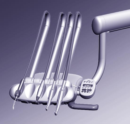
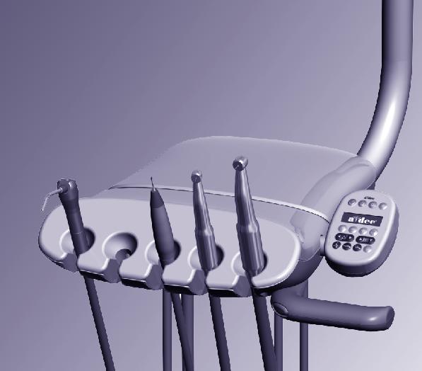
4 A-dec 300 Delivery Systems Instructions for Use Operate / Adjust Operate / Adjust Power On/Off NOTE A-dec recommends that you perform a shock treatment on the dental unit waterlines before you use the system for the first time. For more information, see Waterline Maintenance on page 20. Baseplate Delivery System Master Toggle (A-dec 332 shown) Chair Power Button Master Toggle Use the master toggle to turn on the power, water, and air. The master toggle is normally located on the delivery system, but may instead be located on the support center or floor box on chairs without a delivery system. If there is no power to the system, verify that the chair power button is pushed in. The chair power must be on in order for the master toggle to control system power. When to Turn Off the Power To save energy, turn off the power at the end of the work day and during longer periods of non-use. Status Light Touchpads and the Status Light The A-dec logo on the touchpad illuminates when the system is on and ready for use. If the status light blinks, it may indicate that a safety feature has interrupted chair motion. See Chair Safety Features on page 3 for more information. For complete details on touchpad functionality, please see Touchpad Controls on page 6. 2


5 Chair Safety Features Chair Stop Plate A-dec dental chairs and systems include several features designed to improve safety. Activated stop switches may halt the chair or prevent it from moving. To help ensure uninterrupted chair motion: remove any potential obstructions under the chair and attached modules avoid pressing the foot control disc or lever keep handpieces properly seated in their holders If the Chair Stops Unexpectedly Check the actions listed above to correct the condition. If the downward movement of the chair stopped because of an obstruction, use the touchpad or footswitch to raise the chair and remove the obstruction. Autoclavable Syringe Water Air 2 Clicks To install the A-dec syringe tip, push the tip in until you feel two clicks. Press both buttons simultaneously for the air/water spray. IMPORTANT For detailed instructions on syringe usage, flow adjustment, and maintenance, see the A-dec Syringes Instructions for Use (p/n ) Rev G 3


 Speed + (dry) Run the optional accessory or chip blower.")
6 A-dec 300 Delivery Systems Instructions for Use Operate / Adjust Handpiece Activation and Operation To activate a handpiece, lift it from the holder or pull the whip forward. Use the foot control to perform the desired handpiece operation. Accessory/ Chip Blower Button Wet/Dry Toggle Run/ Speed + Control Operation Procedure Disc Foot Control Run a handpiece. Run a handpiece with or without water coolant. Run the optional accessory or chip blower. Operate the intraoral camera. Press on the disc. Push down to increase speed. Move the wet/dry toggle toward the blue dot for wet operation or away from the blue dot for dry operation. Then press on the disc. Press the accessory/chip blower button.* Press on the disc to capture an image.* Lever Foot Control Run a handpiece with water coolant. Move the lever to the left. Move farther to increase speed. Accessory/ Chip Blower Switch Run a handpiece without water coolant. Move the lever to the right. Move farther to increase speed. Speed + (wet) Speed + (dry) Run the optional accessory or chip blower. Operate the intraoral camera. Press the accessory/chip blower switch.* Move the lever to the left or right to capture an image.* * Contact your authorized A-dec dealer for questions about the operation or configuration of your integrated A-dec accessories. NOTE The lever foot control function can be reversed by a technician (change left direction to dry, right direction to wet). For more details, contact your authorized A-dec dealer. For handpiece coolant adjustments, see page 14. 4
. The brake does not restrict side-to-side movement. To adjust the control head height: 1.")
 To adjust the control head height on systems with manual height adjustment: 1.")
7 Control Head Positioning Flexarm Brake On systems with a counterbalanced flexarm, an integrated brake maintains the vertical position of the control head (with up to 8 lb [3.6 kg] of additional weight). The brake does not restrict side-to-side movement. To adjust the control head height: 1. Press and hold the button to disengage the brake while you position the control head. 2. Release the button to engage the brake. Control Arm Stop Ring Control Arm Stop Tension Setscrews Manual Height Adjustment (336 delivery system only) To adjust the control head height on systems with manual height adjustment: 1. Lift the control arm. NOTE The height adjustment range for the control arm is 5" (127 mm). 2. Slide the stop ring to the desired height groove. 3. Lower the control arm and stop ring into the control arm stop. If the control arm is difficult to lift or rotate, or rotates too freely, use a 3/32" hex key to loosen or tighten the two tension setscrews Rev G 5


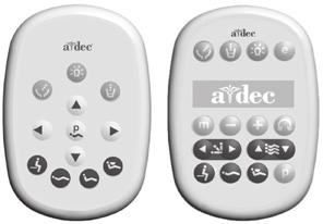
8 A-dec 300 Delivery Systems Instructions for Use Operate / Adjust Touchpad Controls The A-dec touchpad and footswitch control chair movement in the same way. See your dental chair Instructions for Use for detailed information about your footswitch controls. Basic Touchpad Functions Your A-dec 300 system may include a standard or deluxe touchpad, or both. The standard touchpad operates the chair, cuspidor, and dental light functions. The deluxe touchpad adds functions for electric motors and other integrated clinical devices. Both touchpads provide manual and programmable controls. Dental Light Bowl Rinse Cupfill Dental Light Bowl Rinse Cupfill Endodontics/ Electric Motor Controls Manual Chair Controls Programmable Chair Controls Standard Touchpad Deluxe Touchpad 6


9 Touchpad Controls (continued) Standard Touchpad Deluxe Touchpad Press and hold an arrow button until the chair is in the desired position. The horizontal arrows raise and lower the chair back. The vertical arrows raise and lower the chair base. Chair Back Chair Base Standard Touchpad Manual Chair Controls Programmable Chair Controls Deluxe Touchpad Press and release a programmable button to move the chair to a preset position. These buttons are programmed at the factory as follows: Icon Programmable Chair Buttons WARNING Ensure that the patient is positioned safely before using the manual or programmable chair controls. Never leave the patient unattended while the chair is in motion. Always take extra care with small children and patients with limited mobility. To stop the chair at any point during programmed movement, push any chair positioning button on the footswitch or touchpad Rev G Position Factory Setting Entry/Exit Positions the chair for patient entry/exit. Treatment 1 Positions the chair base and back down. Treatment 2 Positions the chair base down and back partially up (standard touchpad only). X-ray/Rinse Moves the chair to either x-ray or rinse position. Press again to move the chair to the previous position. Note: Touchpad symbols are proprietary to A-dec Inc. 7
10 A-dec 300 Delivery Systems Instructions for Use Operate / Adjust Touchpad Controls (continued) Reprogram Entry/Exit, Treatment 1 and 2* Buttons Standard Touchpad To change the factory preset chair positions assigned to the entry/exit and treatment buttons (,, *): Program Button Entry/Exit X-ray/Rinse Treatment 1 Treatment 2 1. Use the manual controls to position the chair as desired. or. One beep indicates that the program2. Press and release ming mode is on. 3. Within five seconds, press the chair position button you wish to reprogram (for example, press ). Three beeps confirm that the new setting is programmed into memory. * Note: The deluxe touchpad does not include a Treatment 2 button. Reprogram X-Ray/Rinse Button Deluxe Touchpad The x-ray/rinse button ( ) is preset to move the chair and patient into an upright position for x-rays or cuspidor access. A second press of returns the chair to the previous position. You can reprogram to function in a similar way to the other programmable chair preset buttons. To change its function: Entry/Exit Treatment 1 Program Button X-ray/Rinse 1. Press and hold or One beep indicates preset button. and at the same time for three seconds. is set as another programmable chair Three beeps confirm that is configured as the x-ray/rinse factory preset (which toggles between the x-ray/rinse and the previous chair position). 2. If you reprogram as another programmable button and want to assign a different chair position, follow the steps outlined in Reprogram Entry/Exit, Treatment 1 and 2* Buttons above. 8

11 Touchpad Controls (continued) Standard Touchpad Deluxe Touchpad Dental Light Program Button Dental Light Dental Light Auto On/Off Feature The auto on/off feature turns the A-dec light on once the chair reaches a preset treatment position. When you press or, the dental light turns off and the chair moves to that preset position. To disable the auto on/off feature, press and hold the program button ( or ) and at the same time for three seconds until you hear one beep. To enable the auto on/off feature, press and hold or and at the same time for three seconds until you hear three beeps. For more information about dental light functions, see your dental light Instructions for Use. Program Button Rev G 9
12 A-dec 300 Delivery Systems Instructions for Use Operate / Adjust Electric Handpiece Settings (deluxe touchpad only) Standard Mode To activate the electric motor, lift the handpiece from the holder. The touchpad screen displays the previous settings used for that handpiece position. Standard mode provides four factory preset speeds for electric motors: Memory Indicator Standard Mode Display Memory Setting m1 Factory Preset Speed 2,000 rpm m2 10,000 rpm Memory Button m3 20,000 rpm m4 36,000 rpm You can reprogram these memory settings with your own specific preset speeds. A total of eight customized settings per handpiece is possible (four in standard mode and four in endodontics mode). To program the handpiece setting: 1. Press or until the rpm setting you want displays on the touchpad screen. 2. Press to save it to memory. One beep sounds. 3. Press to display the m1 through m4 memory settings. When the desired memory setting displays, press. Three beeps confirm the setting. 10

13 Electric Handpiece Settings (deluxe touchpad only) (continued) Memory Indicator Memory Button Endo Mode Button Endo Mode Display Endodontics (Endo) Mode In addition to handpiece speed adjustments, the endo mode allows you to change a number of settings based on the specific file and desired handpiece behavior. Icons on the touchpad screen reflect the settings. NOTE For more information regarding speed and torque limits for a specific file, consult the file manufacturer. To program the handpiece setting: 1. Lift the handpiece from the holder. 2. If the touchpad screen does not display the endo mode, press. 3. To change settings in endo mode, press or. A white reverse video box displays on the touchpad screen. 4. Use the chair positioning buttons to move from setting to setting on the touchpad screen. 5. Use or to change the setting as desired. 6. To set the speed limit, torque limit, or ratio into memory, press. One beep sounds. 7. Press to display the m1 through m4 memory settings. When the desired memory setting displays, press. Three beeps confirm the setting Rev G 11
14 A-dec 300 Delivery Systems Instructions for Use Operate / Adjust Electric Handpiece Settings (deluxe touchpad only) (continued) Endo Mode Touchpad Screen Icons Icon Setting Description Speed Setpoint for file speed limit. For more information, consult your file manufacturer. Endo Mode Button Torque Torque Units Ratio Setpoint for file torque limit. For more information, consult your file manufacturer. Toggles between newton centimeters (N cm) and gram centimeters (g cm). Adjusting this setting for one handpiece changes it for all handpiece settings. Note: 1 N cm = 102 g cm. Sets the handpiece ratio. For more information, consult your handpiece manufacturer. Endo Mode Display Ratio Torque Speed Forward/ Reverse Indicator Auto Mode Indicator Forward/ Reverse Button Auto Modes Auto Stop Auto Reverse Auto Forward Adjusting this setting for one handpiece changes it for all handpiece settings. The auto mode indicator displays inside of the forward/ reverse indicator. When the file reaches the torque limit, the motor shuts off. When the file reaches the torque limit, the motor stops and reverses direction. When the file reaches the torque limit, the motor stops, reverses 3 turns, then changes back to forward again Note: If the file is stuck, the auto forward cycle repeats three times before the motor stops. Forward/Reverse Button The forward/reverse button changes the electric motor s direction. The system defaults to the forward position when you return the motor to the holder or turn off the system. In reverse mode, the screen icon flashes continuously. 12

15 Touchpad Help Messages Help Message The deluxe touchpad screen displays help messages for disabled operations. When a help message appears, record the screen message and the function you were performing in case service is required. For complete details on help messages, see the Regulatory Information, Specifications, and Warranty document (p/n ), which is available in the Document Library at Other Handpiece and Accessory Settings See your authorized A-dec dealer to change any of these handpiece and accessory settings, if applicable: Auto-Off Delay determines how long the handpiece light remains on if the foot control is released. The default setting is 5 seconds. On When Selected specifies whether the handpiece light turns on or remains off when the handpiece is removed from the holder. The default setting is on. On in Endo specifies whether the handpiece light turns on or off when the endo mode is selected. The default setting is off, which is recommended to reduce heat and extend bulb life. Ultrasonic Colors for Acteon ultrasonic instruments, specifies whether color-coded tip categories are on or off. The default is on. Voltage Adjustment allows for customized light output voltage for each handpiece position. The default setting is 3.2 VDC Rev G 13

16 A-dec 300 Delivery Systems Instructions for Use Operate / Adjust Handpiece Coolant Adjustments CAUTION When performing this procedure, do not attempt to completely shut off the water or air flow. The adjustment knobs are not designed to completely shut off flow and can damage the control block if you apply too much force. Air Coolant Adjustment Knob Water Coolant Adjustment Knobs The air coolant knob on your delivery system simultaneously adjusts air flow to all handpiece positions. Each water coolant knob adjusts water flow to a single position. Use the following process to adjust for the desired handpiece coolant atomization: 1. Insert a bur into each handpiece you are adjusting. 2. Turn the air coolant adjustment knob clockwise until coolant flow stops. 3. Lift the handpiece from the holder, or pull the whip forward, and do one of the following: On a disc foot control: flip the wet/dry toggle to water (toward the blue dot) and press the disc all the way down. On a lever foot control: move the lever all the way to the left. 4. Locate the water coolant adjustment knob for the handpiece position you are adjusting and turn it clockwise until coolant flow stops. 5. Slowly turn the water coolant adjustment knob counterclockwise until water droplets are expelled from every water port on the handpiece head. Return the handpiece to the holder. 6. Repeat steps 3 through 5 for each handpiece. 7. To set the air coolant for the system, lift a handpiece from the holder or pull the whip forward. 8. Turn the air coolant adjustment knob counterclockwise until you achieve the desired atomization at the cutting surface of the bur. Disc Foot Control Wet/Dry Toggle Lever Foot Control CAUTION Do not continue turning the air coolant adjustment knob counterclockwise after the air coolant stops increasing. The stem may come out of the control block. 9. If you require more water coolant, increase the water output in step 5 as needed. 14
 attached to the handpiece tubing.")


17 Handpiece Drive Air Adjustments Drive Air Message You can check drive air pressure on the deluxe touchpad screen by pressing and at the same time. For systems with a standard touchpad, and for the most accurate drive air measurement, use a handpiece pressure gauge (A-dec p/n ) attached to the handpiece tubing. To adjust the drive air pressure for each handpiece: Cover Screws 1. Remove the control head cover screws. Remove the cover and locate the drive air pressure controls inside. 2. Lift the handpiece from the holder or pull the whip forward. 3. Do one of the following: On a disc foot control: flip the wet/dry toggle to dry, and press the disc all the way down. On a lever foot control: move the lever all the way to the right. 4. With the handpiece running, check the deluxe touchpad readout or handpiece pressure gauge. 5. Adjust the handpiece drive air pressure to meet the manufacturer s specifications. Turn the control stem clockwise to decrease flow and counterclockwise to increase flow. CAUTION See your handpiece documentation for the drive air pressure specification. Exceeding manufacturer s recommendations increases the risk of damage and may significantly decrease the life of your handpiece components. Wet/Dry Toggle Disc Foot Control Lever Foot Control Rev G 15


18 A-dec 300 Delivery Systems Instructions for Use Operate / Adjust Rotational Adjustments Control Head If the control head is too loose or difficult to rotate, use a 5/32" hex key to adjust the tension screw under the control head. Flexarm If the control head begins to drift right or left, use a 1/8" hex key to adjust the setscrew tension for the flexarm rotation. 16


19 Rotational Adjustments (continued) Traditional System Hex Key Tray Holder If the tray holder rotation is too tight or too loose, use a 9/64" hex key to adjust the tension: 1. Insert the hex key through the mounting bracket. If necessary, rotate the holder or arm until the key slides completely into the mounting bracket. 2. While holding the bracket stationary, turn the tray holder clockwise to increase the tension or counterclockwise to reduce the tension. For Continental -style delivery, there are two adjustment locations: under the control head and under the tray holder. Continental System Hex Key Hex Key Rev G 17


20 A-dec 300 Delivery Systems Instructions for Use Operate / Adjust Vertical Adjustments Flexarm End Cap Spring Tension Rod Button Head Screw 5/16" Socket and Ratchet If the control head falls or rises rapidly when you flip the master toggle to the off position, complete these steps to adjust the flexarm spring tension: 1. Flip the master toggle to the on position. 2. Load the control head for normal use, attaching handpieces and placing a tray on the tray holder. 3. Position the control head so the flexarm is level. 4. Use a 1/8" hex key to loosen the button head screw that secures the end cap farthest from the control head, then pull the cap straight out. 5. Flip the master toggle to the off position. 6. Use a 5/16" socket and ratchet to adjust the flexarm spring tension rod until the control head rises gradually when you flip the master toggle to the off position. If the control head rises rapidly, turn the rod counterclockwise. If the control head falls, turn the rod clockwise. 18


21 Clean / Maintain Handpiece Tubing Use the flush toggle to move a high volume of water through the handpiece tubing. To flush the tubing after each patient: 1. Disconnect the handpieces. 2. Hold all of the handpiece tubing that uses water coolant over a sink, cuspidor bowl, or basin. 3. Hold the flush toggle down for seconds. NOTE Discharge all tubing air and water lines for seconds after each patient. Flush Toggle Oil Collector Service the oil collector on the delivery system once a week for normal usage and more often for heavier use. To service: 1. Unsnap the oil collector cover from the control head and discard the old gauze. Do not remove the foam muffler. 2. Fold a new gauze pad (2" x 2" [51 mm x 51 mm]) into quarters and place it inside the cover. 3. Snap the oil collector cover closed Rev G 19


22 A-dec 300 Delivery Systems Instructions for Use Clean / Maintain Barrier Protection NOTE For proper use and disposal of barriers, see the instructions provided by the barrier manufacturer. A-dec recommends barrier protection for all applicable touch and transfer surfaces. Touch surfaces are areas that come into contact with hands and become potential cross-contamination points during dental procedures. Transfer surfaces are areas that come into contact with instruments and other inanimate objects. In the USA, barriers must be produced under the Current Good Manufacturing Practice (CGMP) as specified by the U.S. Food and Drug Administration (USFDA). For regions outside the USA, refer to the medical device regulations specific to your location. IMPORTANT For recommendations on cleaning and chemical disinfection of touch and transfer surfaces (where barrier protection is not applicable or when barriers are compromised), please see the A-dec Equipment Asepsis Guide (p/n ). Waterline Maintenance Self-Contained Water Bottle A-dec recommends that you perform a shock treatment on the dental unit waterlines before you use the system for the first time. For on-going waterline maintenance, A-dec recommends a three-part protocol: continuous use of A-dec ICX waterline treatment tablets, regular dental unit water monitoring, and shock treatment. IMPORTANT For complete details on how to maintain good water quality in your system, see the Instructions for Use provided with ICX and your self-contained water bottle: A-dec ICX... p/n A-dec Self-Contained Water System... p/n Waterline Maintenance Guide... p/n

23 Utilities and Shutoff Valves Quad Outlet Box Drain Moisture Separator Vacuum Line The utilities for A-dec chair-mounted systems are located in the contoured floor box under your chair. To access, lift the cover up and off the floor box frame. CAUTION When removing or replacing covers, take care not to damage any wiring or tubing. Verify that the covers are secure after replacing them. Manual Water Shutoff Valve Filter Housing O-Ring Filter Beveled Edge Manual Air Shutoff Valve Manual Air Shutoff Valve CAUTION To ensure proper operation, install the filter with the beveled edge facing the manifold. The manual shutoff valves control the air and water to the system. Leave these valves completely open (turned counterclockwise) during normal use to prevent leaks. From the valves, air and water pass through separate filters before entering the pre-regulators. Replace these filters when they become clogged and restrict flow. To check for a clogged air or water filter: 1. Flip the master toggle to the on position. 2. While watching the air pressure gauge, press the syringe air button. If the pressure drops by more than 15 psi, replace the air filter. 3. While watching the cuspidor, press the bowl rinse button. If the water flow fades or stops, replace the water filter. To replace the filter: 1. Flip the master toggle to the off position and close the shutoff valve (turn clockwise). 2. Bleed the system of air and water pressure by operating the syringe buttons until air and water no longer flow. 3. Using a standard screwdriver, remove the filter housing from the water pre-regulator assembly and remove the filter. 4. Replace the filter if it is clogged or discolored. Install the filter with the beveled edge facing the manifold. 5. Open the shutoff valves, flip the master toggle to the on position, and operate the bowl rinse to remove air from the waterline Rev G 21


24 A-dec 300 Delivery Systems Instructions for Use Clean / Maintain Utilities and Shutoff Valves (continued) Filter Housing Water Regulator Water Screen Manual Water Shutoff Valve The manual water shutoff valves include a screen to prevent larger debris from entering the system. Periodically check and replace this screen to ensure unrestricted water flow. To replace the water screen: 1. Flip the master toggle to the off position and close the shutoff valves (turn clockwise). 2. Use a 5/8" or adjustable wrench to loosen the compression nut on the manual water shutoff valve. Then pull the water regulator out of the shutoff valve. 3. Remove the old screen and replace with the new screen. 4. Reposition the water regulator in the manual shutoff valve outlet and tighten the compression nut. 5. Open the manual water shutoff valve (turn counterclockwise) and flip the master toggle to the on position. Check the fittings for leaks. 22

. 4. Replace the bulb. 5.")

25 Bulb for Fiber-Optic Tubing Bulb Silicone Tubing Bulb Vinyl Tubing Handpiece Nut To replace the bulb in your fiber-optic 5-hole silicone or vinyl tubing: 1. Disconnect the handpiece and quick-connector coupling from the tubing. 2. Pull back the metal handpiece nut. 3. Slide back the metal portion of the handpiece terminal (silicone tubing only). 4. Replace the bulb. 5. Reinsert the metal portion of the terminal into the plastic portion (silicone tubing only). 6. Carefully slide the handpiece nut back over terminal. IMPORTANT To replace the bulbs in your handpieces or quick-disconnect couplings, see the instructions that came with your handpieces Rev G 23
, which is available in the Document Library at www.a-dec.com. Minimum Air, Water, and Vacuum Service Requirements Air: 2.5 scfm (71 SL/min) at 80-125 psi (550-860 kpa) minimum Water: 1.")
26 A-dec 300 Delivery Systems Instructions for Use Specifications Specifications Warranty Warranty information is provided in the Regulatory Information, Specifications, and Warranty document (p/n ), which is available in the Document Library at Minimum Air, Water, and Vacuum Service Requirements Air: 2.5 scfm (71 SL/min) at psi ( kpa) minimum Water: 1.5 gpm (5.7 L/min) at 60±20 psi (410±140 kpa) minimum Vacuum: (wet): 9 scfm (255 SL/min) at 10±2 inches of Hg (34±7 kpa) minimun (dry): 12 scfm (340 SL/min) at 4.5±1 inches of Hg (16±3.5 kpa) minimum IMPORTANT For electrical specifications, identification of symbols, and other regulatory requirements, see the Regulatory Information, Specifications, and Warranty document (p/n ), which is available in the Document Library at NOTE Specifications are subject to change without notice. Requirements may vary depending on your location. For more information, contact your authorized A-dec dealer. 24
27
28 A-dec Headquarters 2601 Crestview Drive Newberg, Oregon United States Tel: within USA/CAN Tel: outside USA/CAN Fax: A-dec Australia Unit Ricketty Street Mascot, NSW 2020 Australia Tel: within AUS Tel: +61.(0) outside AUS A-dec China A-dec (Hangzhou) Dental Equipment Co., Ltd. 528 Shunfeng Road Qianjiang Economic Development Zone Hangzhou , Zheijiang, China Tel: within China Tel: outside China A-dec United Kingdom EU Authorized Representative Austin House, 11 Liberty Way Nuneaton, Warwickshire CV11 6RZ England Tel: 0800.ADEC.UK ( ) within UK Tel: +44.(0) outside UK ÍvÈ.ÇÂ È.009Î Rev G Copyright 2017 A-dec Inc. All rights reserved. IFUcov5
A-dec 500 Delivery Systems
 Instructions for Use A-dec 500 Delivery Systems Models 532, 533, and 542 A-dec 500 Delivery Systems Instructions for Use Copyright 2016 A-dec Inc. All rights reserved. A-dec Inc. makes no warranty of any
Instructions for Use. A-dec 4631 Duo Delivery System and A-dec 4635 Assistant s
 Instructions for Use A-dec 4631 Duo Delivery System and A-dec 4635 Assistant s 85.2643.00 Copyright 2016 A-dec Inc. All rights reserved. A-dec Inc. makes no warranty of any kind with regard to this material,
A-dec 300 LED Dental Light
 Instructions for Use A-dec 300 LED Dental Light Models 371L 378L A-dec 300 LED Dental Light Instructions for Use Copyright 2018 A-dec Inc. All rights reserved. A-dec Inc. makes no warranty of any kind
Assistant s Instrumentation T
 Instructions for Use Assistant s Instrumentation 85.2610.00 T Copyright 2015 A-dec Inc. All rights reserved. A-dec Inc. makes no warranty of any kind with regard to this material, including, but not limited
Instructions for Use. Cascade 2615 Cart
 Instructions for Use Cascade 2615 Cart 85.0664.00 Copyright 2016 A-dec Inc. All rights reserved. A-dec Inc. makes no warranty of any kind with regard to this material, including, but not limited to, the
Instructions for Use. Performer. Dental Chair, Delivery System, Assistant s Instrumentation, Support Center with Cuspidor, and Light
 Instructions for Use Performer Dental Chair, Delivery System, Assistant s Instrumentation, Support Center with Cuspidor, and Light Performer Instructions for Use Copyright 2017 A-dec Inc. All rights reserved.
A-dec 200 Service Guide Contents
 A-dec 200 Service Guide 1 A-dec 200 Service Guide Contents Overview... 3 Get Support... 3 International Customer Service... 3 Other Sources of Information... 3 Electronic Documentation... 3 A-dec 200 System
A-dec 541 Delivery System and 545 Assistant s Instrumentation
 Installation Guide A-dec 541 Delivery System and 545 Assistant s Instrumentation Before You Begin A-dec 545 12 O Clock Assistant s Instrumentation The instructions are the same for installing both the
Pre-Installation Guide Performer
 Pre-Installation Guide Performer Contents Structural Requirements... 1 Dental Patient Chair Interface Requirement... 1 Utility Requirements... 1 Utility Specifications... 2 Electrical Ratings... 3 Shipping
A-dec O Clock Delivery System
 Installation Guide A-dec 500 12 O Clock Delivery System Before You Begin A-dec 545 12 O Clock Assistant s Instrumentation Before starting the installation: Check with local building and code authorities
INSTRUCTIONS FOR USE. A-dec 311 Dental Chair
 INSTRUCTIONS FOR USE A-dec 311 Dental Chair A-DEC 311 D ENTAL CHAIR I NSTRUCTIONS FOR USE Copyright 2008 A-dec Inc. All rights reserved. A-dec Inc. makes no warranty of any kind with regard to this material,
A-dec 311, 411, and 511 Dental Chairs Service Reference
 A-dec,, and Dental Chairs Service Reference Copyright Regulatory Information Contents 0 A-dec Inc. All rights reserved. A-dec Inc. makes no warranty of any kind with regard to this material, including,
A-dec 542 Side Delivery System I NSTALLATION GUIDE
 -dec 542 Side Delivery System I NSTLLTION GUIDE This document contains installation instructions for the -dec 542 side delivery system. NOTE Depending on your equipment configuration, some steps in the
The A-dec Difference.
 A-dec 200 The A-dec Difference. The best way to discover what dentists need in a chair and delivery system is to ask. We did. And the A-dec 200 design reflects the way dental teams work, and purposefully
Instructions for Use. A-dec EA-30. Electric Motor System
 Instructions for Use A-dec EA-30 Electric Motor System Copyright 2012 A-dec Inc. All rights reserved. A-dec Inc. makes no warranty of any kind with regard to this material, including, but not limited to,
DECADE 1021 SOLO CHAIR
 Owner's Guide DECADE 1021 SOLO CHAIR 85-2626-00 Warranty A-dec warrants its products against defects in material or workmanship for one year from time of delivery (except for handpieces which have a warranty
A-dec 371L or 571L Dental Light on an A-dec 361, 362, or 363 Support Center INSTALLATION GUIDE
 A-dec 37L or 57L Dental Light on an A-dec 36, 36, or 363 Support Center INSTALLATION GUIDE 37L 57L Before You Begin WARNING Failure to turn off or disconnect the power before you begin this procedure can
The A-dec Difference Built for Life
 A-dec 300 The A-dec Difference Built for Life At A-dec, no detail is too small, right down to the bolts that go into our products. That s why we manufacture a large majority of our finished dental equipment
The A-dec Difference Built for Life
 A-dec 300 The A-dec Difference Built for Life At A-dec, no detail is too small, right down to the bolts that go into our products. That s why we manufacture a large majority of our finished dental equipment
A-dec 351 Assistant s Instrumentation on an A-dec 311/411/511 Dental Chair INSTALLATION GUIDE
 A-dec 351 Assistant s Instrumentation on an A-dec 311/411/511 Dental Chair INSTALLATION GUIDE Contents Before You Begin.......... 2 Install the Rigid Arm....... 3 Connect the Electrical Wires and Data
The A-dec Difference Built for Life
 A-dec 300 The A-dec Difference Built for Life At A-dec, no detail is too small, right down to the bolts that go into our products. That s why we manufacture a large majority of our finished dental equipment
A-dec Dental Lights on an A-dec 300 Base Mount Post INSTALLATION GUIDE
 A-dec Dental Lights on an A-dec 300 Base Mount Post INSTALLATION GUIDE Before You Begin Turn off the power to the system before you begin the installation. DANGER Failure to turn off the power before you
Owner's Guide CASCADE 2671 DUO CART AND CASCADE 3171 DUO WALL-MOUNT
 Owner's Guide CASCADE 2671 DUO CART AND CASCADE 3171 DUO WALL-MOUNT 85.2641.00 ALPHABETICAL EQUIVALENT TO THE NUMERAL OF THE MONTH MANUFACTURED A B C D E F G H I J K L January February March April May
Owner s Guide PERFORMER III
 Owner s Guide PERFORMER III 85.2638.00 R ALPHABETICAL EQUIVALENT TO THE NUMERAL OF THE MONTH MANUFACTURED A B C D E F G H I J K L January February March April May June July August September October November
CASCADE CHAIR-MOUNTED HANDPIECE CONTROL WITH CASCADE MASTER SERIES TOUCH PAD
 R A-DEC INC. 2601 CRESTVIEW DRIVE POST OFFICE BOX 111 NEWBERG, OREGON 97132 USA TELEPHONE (503)-538-9471 DESIGNATED E.U. REPRESENTATIVE: A-DEC DENTAL U.K., LTD. AUSTIN HOUSE 11 LIBERTY WAY ATTLEBOROUGH
Cascade 3072 Delivery System INSTALLATION GUIDE
 Cascade 3072 Delivery System INSTALLATION GUIDE Getting Started Figure 1. Cascade 3072 Delivery System See the section below that applies to your unit. the Wall............. 1 Preference II 5512 Cabinet......................................
Instructions for Use. A-dec EA-53 Electric Motor
 Instructions for Use A-dec EA-53 Electric Motor A-dec EA-53 Electric Motor Instructions for Use Copyright 2014 A-dec Inc. All rights reserved. A-dec Inc. makes no warranty of any kind with regard to this
INSTALLATION INSTRUCTIONS CASCADE 3181 DUO DELIVERY SYSTEM TO PREFERENCECOLLECTION 5580
 R A-DEC INC. 2601 CRESTVIEW DRIVE POST OFFICE BOX 111 NEWBERG, OREGON 97132 USA TELEPHONE (503)-538-9471 DESIGNATED E.U. REPRESENTATIVE: A-DEC DENTAL U.K., LTD. AUSTIN HOUSE 11 LIBERTY WAY ATTLEBOROUGH
A-dec 311 Dental Chair and Related Systems
 Pre-Installation Guide A-dec 311 Dental Chair and Related Systems A-dec 311 Dental Chair with 332 Radius -Style Delivery System and 572 Dental Light This document contains technical specifications for
A-dec 336 Delivery System on an A-dec 411 or 511 Dental Chair INSTALLATION GUIDE
 A-dec 6 Delivery System on an A-dec 4 or 5 Dental Chair INSTALLATION GUIDE Before You Install the 6 Delivery System Install the Rigid Arm A-dec 4 Dental Chair: Follow the instructions for installing the
Service Guide A-DEC SIMULATORS. Mobile (4810) and Stationary (4820)
 and Stationary (4820)") Service Guide A-DEC SIMULATORS Mobile (4810) and Stationary (4820) A-DEC M OBILE AND STATIONARY SIMULATORS 4810 AND 4820 S ERVICE GUIDE Copyright 2015 A-dec Inc. All rights reserved. 2601 Crestview Drive,
Service Guide A-DEC SIMULATORS Mobile (4810) and Stationary (4820) A-DEC M OBILE AND STATIONARY SIMULATORS 4810 AND 4820 S ERVICE GUIDE Copyright 2015 A-dec Inc. All rights reserved. 2601 Crestview Drive,
Legendary A-dec Reliability
 A-dec 500 Legendary A-dec Reliability You can count on A-dec equipment to work when you do. Innovative Engineering Legendary A-dec reliability starts with our design philosophy create innovative, feature-rich
A-dec 200 P RE-INSTALLATION GUIDE
 A-dec 200 P RE-INSTALLATION GUIDE This document contains technical specifications for installing the A-dec 200 equipment line. Contents Structural Requirements...................................................
The A-dec Difference. You can count on A-dec products to work consistently so you can stay focused on what matters most: the patient.
 A-dec 400 The A-dec Difference You can count on A-dec products to work consistently so you can stay focused on what matters most: the patient. Eliminate downtime. Keep ownership costs low. Expect lasting
A-dec Stools. A-dec 1601 Doctor's Stool A-dec 1621, 1622, and 1626 Assistant's Stools
 Instructions for Use -dec Stools -dec 1601 Doctor's Stool -dec 1621, 1622, and 1626 ssistant's Stools -DEC STOOLS I NSTRUCTIONS FOR USE Copyright 2009 -dec Inc. ll rights reserved. -dec Inc. makes no warranty
The A-dec Difference 5 YEAR WARRANTY. You can count on A-dec products to work consistently so you can stay focused on what matters most: the patient.
 A-dec 400 The A-dec Difference You can count on A-dec products to work consistently so you can stay focused on what matters most: the patient. Eliminate downtime. Keep ownership costs low. Expect lasting
Asepsis 21 Delivery Unit
 INSTALLATION INSTRUCTIONS for the Console Mounted TM Asepsis 21 Delivery Unit SECTION I - REQUIREMENTS 1. PHYSICAL REQUIREMENTS... 1 2. ELECTRICAL REQUIREMENTS... 1 3. WATER SUPPLY REQUIREMENTS... 1 4.
INSTRUCTIONS FOR USE CASCADE 2615 CART AND 3175 WALL MOUNT
 INSTRUCTIONS FOR USE CASCADE 2615 CART AND 3175 WALL MOUNT 85.0664.00 R Warranty ALPHABETICAL EQUIVALENT TO THE NUMERAL OF THE MONTH MANUFACTURED A B C D E F G H I J K L January February March April May
DECADE 1021 VAC BACK CHAIR
 Owner's Guide DECADE 1021 VAC BACK CHAIR 85-2625-00 Warranty A-dec warrants its products against defects in material or workmanship for one year from time of delivery (except for handpieces which have
A-dec 570L Dental Light on a Non-DCS System INSTALLATION GUIDE
 A-dec 570L Dental Light on a Non-DCS System INSTALLATION GUIDE Non-DCS LED Dental Light 86.0350.00 Rev B Choose an Installation Guide The manual used to install the light depends on whether the system
Legendary A-dec reliability
 A-dec 500 Legendary A-dec reliability You can count on A-dec equipment to work when you do. Innovative engineering Legendary A-dec reliability starts with our design philosophy create innovative, feature-rich
Mounted Instrument Head
 INSTALLATION INSTRUCTIONS for the Asepsis 21 Cabinet TM Mounted Instrument Head SECTION I - REQUIREMENTS 1. PHYSICAL REQUIREMENTS... 1 4. WATER SUPPLY REQUIREMENTS... 1 5. AIR SUPPLY REQUIREMENTS... 1
Loose Components. VetPro 5000 Wall / Cabinet Mount Installation. Applies to Models:
 VetPro 5000 Wall / Cabinet Mount Installation warning Equipment not suitable for use in the presence of a flammable anesthetic mixture. Applies to Models: 8001-001 8001-002 8001-005 8001-006 Loose Components
A-dec 2122/2132 Radius System on A-dec 511 Dental Chair I NSTALLATION GUIDE
 -dec 2122/2132 Radius System on -dec 511 ental hair I NSTLLTION GUIE Introduction This document contains instructions for installing an -dec Radius delivery system on an -dec Model 511 chair. This guide
A-dec Service Guide Edition , 2003
 R Below are the titles of the sections in the 003 edition of the A-dec Service Guide. Click on the title of a section to view it, or click on the bookmarks tab on the left of the window. Both thumbnails
Radius Cuspidor (for Cascade 1040 or Decade 1011/1021 Chairs)
") INSTALLATION INSTRUCTIONS Radius Cuspidor (for Cascade 1040 or Decade 1011/1021 Chairs) You Will Need: Hex key set Level Large flat head screwdriver Pliers 1/2" and 9/16" wrench Cutters Before Beginning
INSTALLATION INSTRUCTIONS Radius Cuspidor (for Cascade 1040 or Decade 1011/1021 Chairs) You Will Need: Hex key set Level Large flat head screwdriver Pliers 1/2" and 9/16" wrench Cutters Before Beginning
Simplicity Chair Mounted Unit
 Simplicity Chair Mounted Unit Installation, Operation & Care Manual DentalEZ MAKES YOUR PRACTICE PERFECT Table of Contents Section I Introduction Specifications... 3 Classifications... 3 Dimensions...
axcs Chair Mounted Unit Installation, Operation and Care Manual
 axcs Chair Mounted Unit Installation, Operation and Care Manual DentalEZ Group 2500 Highway 31 South Bay Minette, AL 36507 Table of Contents Section I Introduction Introduction... 2-3 Specifications...
A-dec LED Dental Light Head on a Demonstration Stand INSTALLATION GUIDE
 A-dec LED Dental Light Head on a Demonstration Stand INSTALLATION GUIDE Introduction Use this installation guide to install an A-dec LED Dental Light Retrofit Kit (28.1924.00 or 28.1925.00) on a custom
X-Calibur BDS Delivery Systems
 X-Calibur BDS Delivery Systems Table of Contents Page Customer Unit Identification Record 1 General Unit Anatomy 2 Types Of Units 3 Description of Components 5 Control Head Features 5 Cuspidor Features
Troubleshooting Guide: Elevance Delivery Systems
 Troubleshooting Guide: Elevance Delivery Systems FOR USE BY MIDMARK TRAINED TECHNICIANS Contents Description / Links Troubleshooting Charts ICM Screens Assistant s Unit Instruments (Elevance & European)
Instructions For Use VATEA. Endodontic Irrigation Device
 Instructions For Use VATEA Endodontic Irrigation Device VATEA Irrigation System Instructions for use 1. Indications for use The VATEA system is intended to be attached to dental handpieces to deliver irrigation
INTRODUCTION TO SERVICING THE A-dec Handpiece Control Blocks
 INTRODUCTION TO SERVICING THE A-dec Handpiece Control Blocks August, 2017 Presented by Mark Micucci Product Engineer Replacement Parts Industries, Inc. Course Overview The Handpiece Control Block (located
: 1250 gpm in the deck mode : 800 gpm while operating in the ground base - Dual Inlet : 1000 gpm while operating in the ground base - Single Inlet
 APOLLO HI-RISER MONITOR STYLE 3433/3431 INSTALLATION, OPERATING, AND MAINTENANCE INSTRUCTIONS The following is intended to provide the basic instructions for installation, operation and maintenance of
Installation Operation Maintenance Troubleshooting Version 1, Oct/09. Palm Beach
 Installation Operation Maintenance Troubleshooting Version 1, Oct/09 1655 Palm Beach Congratulations! All of us at Summit Dental Systems want you to know that your 1655 Palm Beach Cuspidor has been built
Cascade Master Series
 Overview The Cascade Master Series option consists of five components, which control standard chair and delivery system functions. These components include: master touchpad, master 17-watt power supply,
Simplicity Hygiene Unit
 Simplicity Hygiene Unit (Magellan Style) Installation, Operation & Care Manual DentalEZ MAKES YOUR PRACTICE PERFECT Table of Contents Section I Introduction Specifications... 3 Classifications... 3 Dimensions...
1416 Cabinet Unit. Installation Operation Maintenance Troubleshooting Version Dec/17
 Installation Operation Maintenance Troubleshooting Version Dec/17 1416 Cabinet Unit Page 1 of 16 Table of Contents Important Information... 3 Weight & Dimensions... 4 Operator s Instructions... 5 Flow
OPERATION and MAINTENANCE INSTRUCTION MANUAL. ADU-12DCE Task Force Deluxe Portable Pneumatic Dental System
 OPERATION and MAINTENANCE INSTRUCTION MANUAL ADU-12DCE Task Force Deluxe Portable Pneumatic Dental System TABLE OF CONTENTS: Package Contents....................i Introduction.........................1
Galaxy Wall / Cabinet Mounted Unit
 Galaxy Wall / Cabinet Mounted Unit Installation, Operation & Care Manual DentalEZ MAKES YOUR PRACTICE PERFECT Table of Contents Section I Introduction Introduction... 2 Basic Components... 2 Classification...
Regulatory Information and
 Regulatory Information and Introduction A-dec products. The information contained here supersedes regulatory information included in any other document that came with your A-dec product. Equipment Alterations
User s Manual. Table of Contents CAUTION. Model No. MTSC20000
 Model No. MTSC20000 Table of Contents Important Precautions..........2 Limited Warranty..............2 Before You Begin.............3 How to Set Up and Fold the Scooter...............4 How to Operate the
STYLE 3463 FireFox. With Position Feedback Potentiometer
 STYLE 3463 FireFox INSTALLATION, OPERATING and MAINTENANCE INSTRUCTIONS With Position Feedback Potentiometer The following is intended to provide the basic instructions for installation, operating and
( Versions Available)
") STYLE 494 ELECTRIC LADDER PIPE INSTALLATION, OPERATING AND MAINTENANCE INSTRUCTIONS ( Versions Available) The following is intended to provide the basic instructions for installation, operating and maintenance
STYLE 494 ELECTRIC LADDER PIPE INSTALLATION, OPERATING AND MAINTENANCE INSTRUCTIONS ( Versions Available) The following is intended to provide the basic instructions for installation, operating and maintenance
Simplicity Magellan Unit
 Simplicity Magellan Unit Installation, Operation & Care Manual DentalEZ MAKES YOUR PRACTICE PERFECT Table of Contents Section I Introduction Specifications... 2 Classifications... 2-3 Dimensions... 3 Basic
STYLE 3462 FORESTRY BUMPER MONITOR INSTALLATION, OPERATING and MAINTENANCE INSTRUCTIONS
 STYLE 3462 FORESTRY BUMPER MONITOR INSTALLATION, OPERATING and MAINTENANCE INSTRUCTIONS The following is intended to provide the basic instructions for installation, operating and maintenance of the 3462
Mirage Dental Delivery Unit Model 2000 / 2015 Installation Instructions
 Mirage Dental Delivery Unit Model 2000 / 2015 Installation Instructions 851 S. Lawson St. City Of Industry, CA 91748 P626-810-4337 Fax 626-810-4245 REV. 1-1-13 Each Mirage delivery unit will contain the
SERVICE PARTS 2013 Q3 A-dec Authorized Dealer Catalog
 SERVICE PARTS 2013 Q3 A-dec Authorized Dealer Catalog Suggested retail prices effective July 2013 Products priced in this catalog are available in the United States and Canada Welcome To The 2013 Genuine
Equipment Order Guide
 Equipment Order Guide Effective April 1, 2016 DCI EDGE Equipment Order Guide ORDERING INFORMATION When ordering, please include the following information: DCI requires Doctor, Clinic Name and Address before
04979, 04980, 04981, 04982, 04983, 04984, 39054, 39055, 39056, 39057, 39225, 81459,
 Hydraulic Bottle Jacks 04979, 04980, 04981, 04982, 04983, 04984, 39054, 39055, 39056, 39057, 39225, 81459, 82132. These instructions accompanying the product are the original instructions. This document
Mirage Dental Delivery Unit MSP3500/3550 Installation Instructions
 ! Mirage Dental Delivery Unit MSP3500/3550 Installation Instructions TPC 851 S. Lawson St. City Of Industry, CA 91748 P626-810-4337 Fax 626-810-4245 REV. 1-1-13 Table on Contents: Page GENERAL INFORMATION
forest dental australia affordable excellence + designer friendly
 Component Catalogue 204 table of contents section pages light service items............................................ 2-3 handpiece controls..............................................4 arm systems................................................
3-in-1 Electric Jack, Impact Wrench & Air Compressor
 Item No. : 7010 3-in-1 Electric Jack, Impact Wrench & Air Compressor User s Manual We are constantly improving our products so specifications are subject to change without notice. Visit our website for
5000TOC Sensor Service Manual
 Part No. 84449 5000TOC Sensor Service Manual This document contains proprietary information, which is protected by copyright. All rights are reserved. No part of this document may be photocopied (other
Chair Mounted Unit. Installation, Operation and Care Manual. DentalEZ Group 2500 Highway 31 South Bay Minette, AL 36507
 axcs Basic-Duo Chair Mounted Unit Installation, Operation and Care Manual DentalEZ Group 2500 Highway 31 South Bay Minette, AL 36507 Table of Contents Section I Introduction Introduction... 2 Specifications...3
2006 Dynojet Research, Inc. All Rights Reserved. Spring Applied Air Release (SAAR) Brake Assembly Installation
 Brake Assembly Installation") 2006 Dynojet Research, Inc. All Rights Reserved. This manual is copyrighted by Dynojet Research, Inc., hereafter referred to as Dynojet, and all rights are reserved. This manual, as well as the software
2006 Dynojet Research, Inc. All Rights Reserved. This manual is copyrighted by Dynojet Research, Inc., hereafter referred to as Dynojet, and all rights are reserved. This manual, as well as the software
The Belmont Warranty does not cover damage to equipment and upholstery caused by disinfectant solutions. WARRANTY
 Barrier Technique The first choice in the protection of dental equipment should be the use of disposable barrier products. The repeated use of disinfectants on equipment surfaces without the constant removal
Dynojet Research, Inc. All Rights Reserved. Air Fuel Ratio Module Installation and User Guide.
 2014-2015 Dynojet Research, Inc. All Rights Reserved.. This manual is copyrighted by Dynojet Research, Inc., hereafter referred to as Dynojet, and all rights are reserved. This manual, as well as the software
MOOG Medical Devices Group Curlin 6000 Series Ambulatory Infusion Pump PATIENT GUIDE
 MOOG Medical Devices Group Curlin 6000 Series Ambulatory Infusion Pump PATIENT GUIDE TABLE OF CONTENTS Introduction...2 Important keys...2 Installing/Changing the Batteries...3 Preparing Your Therapy...4
User Manuel. Titan Hummer XL
 User Manuel Titan Hummer XL Dear User, Tzora Active Systems Ltd. thanks you for choosing the Titan Hummer-XL and wishes you safe and enjoyable journeys. For proper operation and to maintain the scooter
STYLE 9300 FLOW/PRESSURE METER INSTALLATION & OPERATING INSTRUCTIONS
 STYLE 9300 FLOW/PRESSURE METER INSTALLATION & OPERATING INSTRUCTIONS INTRODUCTION The Style 9300 Flow/Pressure Meter from Akron is designed to offer reliable and accurate service with an easy to install,
Service Manual CDFI1000P CDFI500P
 Service Manual Model Part Number CDFI1000P 6909660100 CDFI500P 6909660200 IMPORTANT SAFETY INFORMATION: Always read this manual first before attempting to service this cassette. For your safety, always
Brake System H TX, H2.0TXS [B475]; H TX [B466] Safety Precautions Maintenance and Repair
![Brake System H TX, H2.0TXS [B475]; H TX [B466] Safety Precautions Maintenance and Repair](/thumbs/86/93834005.jpg "Brake System H TX, H2.0TXS [B475]; H TX [B466] Safety Precautions Maintenance and Repair") HMM180001 Brake System H1.5-1.8TX, H2.0TXS [B475]; H2.5-3.5TX [B466] Safety Precautions Maintenance and Repair When lifting parts or assemblies, make sure all slings, chains, or cables are correctly fastened,
HMM180001 Brake System H1.5-1.8TX, H2.0TXS [B475]; H2.5-3.5TX [B466] Safety Precautions Maintenance and Repair When lifting parts or assemblies, make sure all slings, chains, or cables are correctly fastened,
LS Series. Remix Shaft Installation Instructions REQUIRED TOOLS PARTS WORK SAFELY! PREPARATION/SAFETY PROCEDURES
 REQUIRED TOOLS LS Series Remix Shaft Installation Instructions /8", /6", /2" Allen Wrenches Snap Ring Pliers (Light Duty) /" Combination Wrench Loctite #22 Blue /" Socket w/ /8" Ratchet Electric Drill
Asepsis 21 Delivery Systems
 Asepsis Delivery Systems Chair Mounted Floor Mounted Side / Rear Cart Serial Number Prefixes: PJ, PK, PL, PM, UA, UC, UK, UW & V Service and Parts Manual NOTE: Sterling Grey painted parts are no longer
Air Fuel Ratio Module and AFR-4 Pump Assembly Installation and User Guide.
 2007-2012 Dynojet Research, Inc. All Rights Reserved.. This manual is copyrighted by Dynojet Research, Inc., hereafter referred to as Dynojet, and all rights are reserved. This manual, as well as the software
Procenter Delivery, Console Mounted on an Elevance Chair Installation Guide
 Procenter Delivery, Console Mounted on an Elevance Chair Installation Guide Language of origin: English Equipment Alert Do not remove wraps or packaging from the delivery flex arm assembly until it is
Owner s Manual Nitrate Series Salt Based Filter System
 Owner s Manual Nitrate Series Salt Based Filter System Page 2 Copyright 2012 Enviro Water Solutions Inc. All rights reserved. All information contained herein is the property of Pelican Water Systems.
Level-Up (Towable) System
 System") Level-Up (Towable) System OWNER'S MANUAL Rev: 12.21.2017 Page 1 Level-Up Towable Owner's Manual TABLE OF CONTENTS System and Safety Information 2 Introduction 3 Touch Pad Diagram 3 Prior to Operation 4
Level-Up (Towable) System OWNER'S MANUAL Rev: 12.21.2017 Page 1 Level-Up Towable Owner's Manual TABLE OF CONTENTS System and Safety Information 2 Introduction 3 Touch Pad Diagram 3 Prior to Operation 4
System 3 ZB1PS Device Chassis. Operator s Manual
 System 3 ZB1PS Device Chassis Operator s Manual System 3 ZB1PS Operator's Manual Copyright 2007 Tucker-Davis Technologies, Inc. (TDT). All rights reserved. No part of this manual may be reproduced or transmitted
3-PHASE SMART CONTROLLER STP-SCIIIC INSTALLATION GUIDE
 3-PHASE SMART CONTROLLER STP-SCIIIC INSTALLATION GUIDE The information in this publication is provided for reference only. While every effort has been made to ensure the reliability and accuracy of the
VANGUARD Dental Unit 1
 1 VANGUARD Dental Unit Vanguard 2 The New Vanguard Unit The exciting new Ritter Vanguard Dental Unit is German-engineered to integrate electronic technology with smooth hydraulic movement. It is Ritter
Operator s Manual. Automatic Electric Jack Leveling. The leveling system shall only be operated under the following conditions:
 Operator s Manual with Automatic Leveling Touchpad #140-1226 Control Box #140-1224 co Copyright PowerGear 1/07 #82-L0368 Rev. 0D Contents Before You Level Your Coach 1 Caution 1 Leveling System Operating
Field Service Bulletin
 Field Service Bulletin CNG High Pressure Filter Maintenance ENP-114 Rev. E: July 12, 2017 1. Introduction The Agility Fuel Solutions high pressure filter is designed to catch contaminants that may be introduced
Owner s Manual. Calcite ph Neutralizer
 Owner s Manual Page 2 Copyright 2012 Enviro Water Solutions Inc. All rights reserved. All information contained herein is the property of Pelican Water Systems. Pelican Water Systems makes no warranty
HYDRAULIC LEVELING SYSTEMS OPERATIONS MANUAL (For systems with touch pad part number , , , , or no number at all)
") HYDRAULIC LEVELING SYSTEMS OPERATIONS MANUAL (For systems with touch pad part number 500089, 500105, 500210, 500456, 500535 or no number at all) Visit us on the web at www.powergearus.com 82-L0040-01 Rev.
HYDRAULIC LEVELING SYSTEMS OPERATIONS MANUAL (For systems with touch pad part number 500089, 500105, 500210, 500456, 500535 or no number at all) Visit us on the web at www.powergearus.com 82-L0040-01 Rev.
Installation Operation Maintenance Troubleshooting Version2.1. Feb/09. Led II
 Installation Operation Maintenance Troubleshooting Version2.1. Feb/09 Led II INDEX Safety Regulation 3 Components 4 User s Guide 9 Product Installation 10 Operation Method 11 Maintenance and Repair 13
Heavy Duty Miniature Quick-Change Applicator (Side-Feed Type) with Mechanical or Air Feed Systems
 with Mechanical or Air Feed Systems") Heavy Duty Miniature Quick-Change Applicator (Side-Feed Type) with Mechanical or Air Feed Systems Instruction Sheet 408-8040 30 NOV 17 Rev H Ram Assembly Ram Post Locking Screw Stock Drag Drag Release
Heavy Duty Miniature Quick-Change Applicator (Side-Feed Type) with Mechanical or Air Feed Systems Instruction Sheet 408-8040 30 NOV 17 Rev H Ram Assembly Ram Post Locking Screw Stock Drag Drag Release
Performer Delivery System (Performer I Chair - International, and Performer III Chair)
") Performer elivery System (Performer I hair - International, and Performer III hair) I NSTLLTION UI Introduction This document contains installation instructions for the Performer elivery System (Performer
Performer elivery System (Performer I hair - International, and Performer III hair) I NSTLLTION UI Introduction This document contains installation instructions for the Performer elivery System (Performer
Model 2008 I Battery Operated Irrigation Timer with 3/4 in. Anti-Siphon Valve
 i n s t r u c t i o n m a n u a l Model 2008 I Battery Operated Irrigation Timer with 3/4 in. Anti-Siphon Valve Features Weekly or cyclical programming 4 start times per day in weekly program Irrigation