Installation and Operating Instructions
|
|
|
- Megan Jordan
- 5 years ago
- Views:
Transcription

1 204-07_Aus_Type :12 Uhr Seite 1 Trailer Couplings Installation and Operating Instructions Fitting / Operation / Maintenance / Repair Automatic Trailer Coupling Type 101 AUS Range of application: These installation and operating instructions apply to automatic trailer coupling RINGFEDER type 101 AUS. Type 101 AUS is approved to connect with drawbar eyes 50 according to DIN and drawbar eyes D50 in accordance with the EU directive 94/20 and ECE55-01 as well as drawbar eyes ISO 1102 and in addition with heavy duty drawbar eyes 50 having a correspondingly high D-value. Summary: Fitting Operation Maintenance Repair /2007
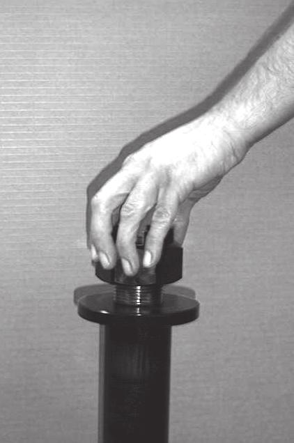
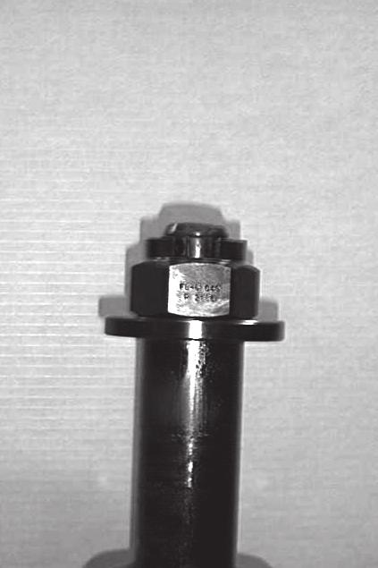
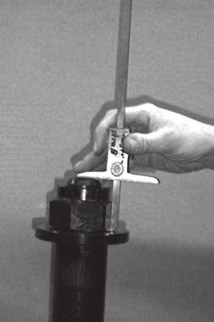
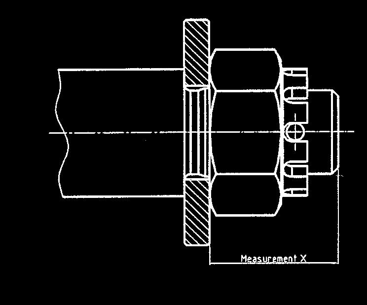
2 204-07_Aus_Type :12 Uhr Seite 2 Installation 1. Remove castle nut (42). 2. Pull tension washer (40), rubber spring (36) and bar guide (38) from the drawbar (1). 3. Fit bar guide (38) contrary to the driving direction to the inner face of the rear drawbeam. Caution: Max thickness of the drawbeam: 35 mm! 4. Tighten the bar guide (38) together with the drawbeam using 4 bolts grade 8.8 and 4 safety nuts grade 8. The heads of the screws have to be mounted on the side of the coupling head (outer side of the drawbeam). Under screws and nuts you have to use washers DIN 125, hardness min 200HV. Bolt length: bolt shank + washer thickness + nut length + at least 2 threads Flange Design d2 Thread Tightening Torque Wrench Size e1xe2 [mm] [mm] (standard thread) [mm] 160 x 100 Ø 21 M Nm Fit tension washer (40) without any other components of the towing device to the bar guide (1) and fully tighten the castle nut (42) by hand. Measure the dimension X (see figures 1 4). Remove castle nut (42) and tension washer (40) again. 6. Fit the coupling head assembly including the front rubber spring (36) and thrust washer (37) to the bar guide (38). If required, regrease drawbar (1) and contact surfaces of thrust washer (37) and bar guide (38). Caution: Never grease the rubber spring! 7. Fit the rear rubber spring (36) and tension washer (40). Caution: Never grease the rubber spring! 8. Grease the contact surfaces of the castle nut (42) and tension washer (40). Screw on and tighten the castle nut (42) until the previously measured dimension X is reached again and secure by means of a cotter pin (43). Min. tightening torque of the castle nut M45x3: 700 Nm using a wrench or nut with a wrench size of 70 mm. To reach the dimension X and the next hole position for the cotter pin even higher tightening torques may be required. Caution: Always tighten to the next hole position. 9. Fit and push on the protective plastic cap (44) carefully. 10. Straighten the coupling. 11. For a retro-fit please refer to the relevant statutory regulations. 2
3 204-07_Aus_Type :12 Uhr Seite 3 Figures 1-4 3

.")
4 204-07_Aus_Type :12 Uhr Seite 4 Operation 1. The trailer coupling is closed and secured, resp. coupled that is to say the towing eye is inserted, the coupling bolt in its lower position, the safety device is engaged, the safety bar/bolt locates over the coupling bolt, the securing knob is in its internal engaged position. 2. Releasing and opening of the trailer coupling: The coupling can only be opened when the coupling jaw is in the central position or in the lateral end positions. To release the trailer coupling the securing knob is pulled out and turned ahead until it has reached its external engaged position. The trailer coupling now is released (Fig. 1). To open the coupling the hand lever is moved to its upper end position and then released. This will cause the coupling bolt to lift up and the towing eye may be extended. Due to the extension of the towing eye the coupling mechanism is again released and thus the coupling repeatedly closed and secured. 3. Opening the trailer coupling to couple the towing eye: To open the trailer coupling proceed as described under item 2 above. The coupling lever is in its upper end position, the coupling is set ready for its next engagement. When inserting the towing eye, the coupling mechanism is released by lifting the coupling bolt. The coupling closes automatically, which means that the coupling bolt is inserted through the towing eye bush in its lower position in the guide bush. The safety device is engaged, that is to say that the safety bar/bolt locates over the coupling bolt, the securing knob is in its internal engaged position, the coupling is closed and secured, the towing eye is engaged (Fig. 2). Check that after each coupling process the safety device is fully engaged. If the securing knob is not in its internal engaged position, the trailer coupling is unsecured and the whole procedure must be repeated. Fig. 1 Fig. 2 Trailer coupling Trailer coupling disengaged/uncoupled closed and secured 4
5 204-07_Aus_Type :12 Uhr Seite 5 Service and maintenance It is most important to always realize that the trailer coupling is a safety part and be handled as such. Regular service, maintenance and lubrication is a prerequisite for a safe and long-term troublefree service-life. The degree of loading and thus the wear of a trailer coupling also depend on the type of trailers, the loads, roads and climatic conditions. The wear limits given under safety check must not be fallen short of ( for example coupling bolt diameter) nor exceeded (for example bore hole diameter bottom guide bush). If daily inspection of the vehicle in operation shows that the function of the trailer coupling has been impaired or strong signs of wear are sensible it is imperative that a safety check as described below be carried out immediately and, if necessary, the specific wearing parts be exchanged. In order to limit the degree of wear on the coupling bolt and drawbar eye bush these components must always be kept clean and lubricated. In case of hard running of the coupling mechanism the coupling head has to be lubricated over the tapered grease nipple (5). The trailer coupling should as far as possible not be cleaned by a steam cleaner (high pressure cleaner). If this cannot be avoided the trailer coupling itself should be closed beforehand. After such cleaning the bearings of the coupling body should be greased with WD40 or a similar high-grade permanent lubricant. After that also the coupling bolt is to be greased and the coupling head be lubricated over the tapered grease nipple (5). Safety check On its safety check the trailer coupling is to be inspected as described below: Functional check by repeatedly opening and closing the coupling. 1. Clean coupling bolt (23) and measure its smallest outside diameter in the bulged area. Wear limit of coupling bolts (in accordance with ISO-standard) 50 mm bolt couplings: 46,5 mm Should the wear limit be reached the coupling bolt and the pertaining locking springs (25), included in the delivery of the coupling bolt have to be replaced by new ones. 2. Measure axial play of the coupling bolt (23). For this purpose close the trailer coupling and push the coupling bolt from underneath upward by means of an appropriate tool. If the axial play should exceed 5 mm the hand lever/locking lever assembly has to be replaced. 3. Control clearance of the coupling bolt (23) in the bottom guide bush (6). The maximum admissible clearance must not exceed 2,5 mm. If necessary, the coupling bolt plus pertaining locking springs (25) or the bottom guide bush, resp. or both have to be replaced by new ones. Control max. diameter of the bottom guide bush (6) in the area of the coupling bolt seat e.g. by means of a slide gauge. Admissible inner dia: max. 36,5 mm Should the wear limit be reached the bottom guide bush has to be replaced by a new one. 5
6 204-07_Aus_Type :12 Uhr Seite 6 4. Control bearing clearance of the drawbar (1) in the drawbar guide (38). Should the clearance between drawbar shaft and bearing bush (39) exceed 1 mm the plastic bearing bushes (39) in the bar guide (38) have to be replaced. Together with these also the rubber springs (36) should be replaced by new ones. 5. Control wear of the wear plate (7). The wear plate should be kept cleanest possible and free from grease, as grease consolidates dust and thereby the wear considerably increases due to the abrasive effect in trailer operation. If the wear plate shows strong signs of wear and tear (4 mm and more) it has to be replaced by a new one. 6. Control axial play (longitudinal play) of the bearing. For this purpose vigorously move the drawbar (not the guiding funnel of the mouth) back and forth in longitudinal direction using both hands. There must not be any axial play (longitudinal play) between the drawbar (1) and the bar guide (38), otherwise the rubber springs (36) have to be replaced. When replacing the rubber springs, at the same time the plastic bearing bushes (39) in the bar guide (38) have to be exchanged as well. 7. Control pivot bearing of the coupling body (3) for longitudinal play. maximum admissible longitudinal play at the upper bearing: 1 mm maximum admissible longitudinal play at the lower bearing: 1 mm When the maximum admissible bearing clearances have been reached the trailer coupling must be repaired. 8. Control coupling body (3) for smooth running. For this purpose move coupling body with the trailer coupling closed to the right and to the left. In case of stiffness the bearings of the coupling body have to be roughly cleaned and greased with WD 40 or a similar high-grade permanent lubricant so that the coupling mouth is smoothly running. By the force of the return spring the coupling body must automatically return / recoil into its central position. Important note: To fix the castellated nut with a cotter pin attend to always using new, corrosion-resisting cotter pins. Moreover, when replacing component parts of the trailer coupling only original RINGFEDER spare parts are to be used, since otherwise a safe performance cannot be safeguarded and every guarantee ceases. Pivot bearings of the coupling body (7,8) max. 4mm
7 204-07_Aus_Type :12 Uhr Seite 7 Repair Disassembly from the vehicle 1. Remove protecting cap (44) (fig. 1). 2. Remove cotter pin (43) (fig. 2). 3. Unscrew castellated nut (42) (fig. 3). 4. Completely pull out coupling head from the bar guide (38) (fig. 4). 5. Remove tension washer (40) and rubber spring (36) from the bar guide (38). 6. Remove thrust washer (37) and rubber spring (36) from the drawbar shaft (fig. 4). Stripping down of the coupling head 1. Detach and remove fastening parts (32 34 and (9) of the top cap (26) (fig. 5). 2. Disassemble locking springs (25) and coupling bolt (23) including lifting sleeve (24) (fig. 6/7). 3. Remove wear plate (7) from the coupling mouth. 4. Detach hexagonal screws (14) at the tab washer (12) (fig. 8). 5. Remove tab washer (12) and return spring (11) (fig. 8). 6. Remove bottom guide bush (6) (fig. 9). 7. Remove coupling body (3) with the remaining fitted parts from the drawbar (1) (fig. 10). 8. Remove top guide bush (2) (fig. 11). Assembly of the coupling head 1. Drive in top guide bush (2) to the drawbar (1) (fig. 11). 2. Fit coupling body (3) on to the drawbar (1) (fig. 10). 3. Grease bottom guide bush (6) and drive through coupling mouth into the draw bar. (The threaded holes of the bottom guide bush must be transverse to the longitudinal axis of the coupling) (fig. 9). 4. Insert return spring (11) (fig. 8). 5. Screw on tab washer (12) (fig. 8). 6. Insert wear plate (7) in coupling mouth and screw up. 7. Insert coupling bolt (23) including lifting sleeve (24) the way that the axis of the pin (24) is transverse to the longitudinal axis of the coupling (fig. 7). 8. Insert locking springs (25) (fig.6). 9. Fill in new grease into the housing. 10. Refit top cap (26) and screw up (fig. 6). 11. Slip on rubber spring (36) and thrust washer (37) to the drawbar (1) (fig. 5). 12. Grease drawbar shaft. Assembly to the vehicle: 1. Grease bearing surface of the thrust washer (37) on the bar guide (38). 2. Fit tension washer (40) without any other components of the towing device to the bar guide (1) and fully tighten the castellated nut (42) by hand. Measure the dimension X (see figures 1 4). Remove castellated nut (42) and tension washer (40) again. 3. Fit the complete coupling head assembly to the bar guide (38) (fig. 4). 4. Slip on rubber spring (36) and tension washer (40) to the drawbar shaft. 5. Screw on castellated nut (42) and tighten according to "fitting instructions - item 8" (fig. 3). 7
8 204-07_Aus_Type :12 Uhr Seite 8 6. Drive in new cotter pin (43) and secure properly (fig. 2). 7. Slip on protecting cap (44) (fig. 1). 8. If necessary, adjust coupling head horizontally to the vehicle by using a lever. Caution: Never grease the rubber springs! Important Note: To fix the castellated nut with a cotter pin attend to always using new, corrosion-resisting cotter pins. Moreover, when replacing component parts of the trailer coupling only original RINGFEDER spare parts are to be used, since otherwise a safe performance cannot be safeguarded and every guarantee ceases. 8
9 204-07_Aus_Type :12 Uhr Seite 9 9
10 204-07_Aus_Type :12 Uhr Seite 10 10


11 204-07_Aus_Type :12 Uhr Seite 11 Trailer Couplings A certified company in accordance with DIN EN ISO 9001:2000 and ISO TS 16949:2002 and DIN EN ISO 14001:1996 VBG GROUP TRUCK EQUIPMENT GMBH Oberschlesienstr. 15 D Krefeld Postfach/ POB D Krefeld Phone +49 (0) Facsimile +49 (0) info@ringfeder.de 11


12 :12 Uhr Seite 12 Trailer Couplings _Aus_Type 101
RINGFEDER. Automatic Trailer Couplings for connecting to 40 mm drawbar eyes according to DIN Type 604/ 605/ 6041/ 6051/ 6061.
 RINGFEDER DE 03 08 99 00 Prospekt Prospect Automatic Trailer Couplings for connecting to 40 mm drawbar eyes according to DIN 74054 Type 604/ 605/ 6041/ 6051/ 6061 Type 6051 Automatic Trailer Couplings
Installation and Operation Instructions RINGFEDER Type 2050 AM RINGFEDER Type 2050 AP
 Installation and Operation Instructions RINGFEDER Type 2050 AM RINGFEDER Type 2050 AP 22.10.2003 10069125 Type 2050 AM General RINGFEDER Type 2050 AM, part no.: 14994532 RINGFEDER Type 2050 AP, part no.:
RINGFEDER 5055-NZ. Automatic Trailer Coupling
 Automatic Trailer Coupling RINGFEDER 5055-NZ also with distance control and remote indicator for heavy duty centre axle trailers using 50 mm drawbar eyes EC type approval according to class C 50-X in compliance
WAP disc brake technology. Assembly, operating and maintenance instructions
 WAP disc brake technology Assembly, operating and maintenance instructions Number MA-025 Date 22.07.2010 1 Please read this operating and service manual before starting the vehicle. It forms part of the
Series Type ROi400 DE EN FR. Montage- und Betriebsanleitung Installation and operating instructions Instructions de montage et d utilisation
 Montage- und Betriebsanleitung Installation and operating instructions Instructions de montage et d utilisation DE EN FR Member of JOST-World Modellreihe Series Type ROi400 Vollautomatische Anhängekupplung
Safety check e Safety and function test...to be kept in the cab
 Safety check 38-123305e 2008-12-15 Safety and function test...to be kept in the cab Warning! Never put your fingers into the coupling mouth due to the danger of them being crushed. An open coupling always
We make life easier for users through
 SPARE PARTS 00 We make life easier for users through the constant development of better systems with high operational reliability and long service life. Couplings, manual, automatic and power-assisted,
Hook coupling UN 76 Installation,operating and maintenance instructions
 Hook coupling UN 76 Installation,operating and maintenance instructions E S ORL DI I S T E M I D I T R A I N O Registration of the installation and the maintenance operations Vehicle data: Type: Registration
Technical Description Edition 2007 Mounting, maintenance and repair of propshafts with flanged universal joints
 Technical Description Edition 2007 Mounting, maintenance and repair of propshafts with flanged universal joints 1. Recommendations Assembly, disassembly, maintenance and repair of propshafts should be
Für Modellreihen / for Series / pour les séries
 Montage- und Betriebsanleitung Installation and operating instructions Instructions de montage et d utilisation D F Member of JOST-World Für Modellreihen / for Series / pour les séries RO i850 B RO i860
3 Axles and brakes. 3.1 Function and construction of the axles Construction Function
 3 Axles and brakes 3.1 Function and construction of the axles 3.1.1 Function Each wheel has an independent suspension system in the axle body (1), so that individual wheel suspension is provided. The swinging
Series Type Модельный ряд ROi500
 Montage- und Betriebsanleitung Installation and operating instructions Instructions de montage et d utilisation Инструкция по монтажу и эксплуатации Member of JOST-World DE EN FR Рус Modellreihe Series
We make life easier for users through
 SPARE PARTS 0 We make life easier for users through the constant development of better systems with high operational reliability and long service life. Couplings, manual, automatic and power-assisted,
Автоматическое тягово-сцепное устройство
 Montage- und Betriebsanleitung Installation and operating instructions Monterings- och driftanvisning Monterings- og bruksanvisningen Инструкция по монтажу и эксплуатации DE SV NO RU Modellreihe Series
Manuelle Kugelkupplung Non-automatic ball coupling Attelage à boule verrouillage manuel
 Montage- und Betriebsanleitung Installation and operating instructions Instructions de montage et d utilisation D F Member of JOST-World Für Modellreihen for Series pour les séries RO i825 B Manuelle Kugelkupplung
1988 Chevrolet Pickup V SUSPENSION - FRONT (4WD)' 'Front Suspension - "V" Series 1988 SUSPENSION - FRONT (4WD) Front Suspension - "V" Series
' 'Front Suspension - V Series 1988 SUSPENSION - FRONT (4WD) Front Suspension - V Series") 1988 SUSPENSION - FRONT (4WD) Front Suspension - "V" Series DESCRIPTION NOTE: Vehicle serial numbers used in this article has been abbreviated for common reference to Chevrolet and GMC models. Chevrolet
1988 SUSPENSION - FRONT (4WD) Front Suspension - "V" Series DESCRIPTION NOTE: Vehicle serial numbers used in this article has been abbreviated for common reference to Chevrolet and GMC models. Chevrolet
Repair Manual VW 02J gearbox. INA GearBOX
 Repair Manual VW 02J gearbox INA GearBOX Special tools Pipe section, 50 mm: Press fitting of synchronizer body for third/fourth gear. Assembly of support bearing for input and output shaft. Part number:
Hydraulic Motors. Radial Piston Motors with fixed displacement Series RM...X Vg = 250 cm³/u cm³/u. Repair manual. Doc.-No.
 Hydraulic Motors Radial Piston Motors with fixed displacement Series RM...X Vg = 250 cm³/u - 900 cm³/u Doc.-No. HM3-005 UK Seite 2 Table of contents 1. General... 3 2. Dismantling the distributor unit...
SUSPENSION - FRONT Infiniti G20 DESCRIPTION ADJUSTMENTS & INSPECTION SUSPENSION Front G20
 SUSPENSION - FRONT 1992 Infiniti G20 1991-92 SUSPENSION Front G20 DESCRIPTION G20 uses a 4-wheel independent multi-link suspension system. Transverse links are connected to bottom of steering knuckle.
RINGFEDER Locking Assemblies. Catalogue. RfN For high torques & axial loads
 RINGFEDER Locking Assemblies GB 03 04 Catalogue RfN 7014 For high torques & axial loads RINGFEDER Locking Assemblies RfN 7014 Please note that our guarantee refers to our products only. Because of the
SUSPENSION - FRONT Toyota Celica DESCRIPTION ADJUSTMENTS & INSPECTION WHEEL ALIGNMENT SPECIFICATIONS & PROCEDURES WHEEL BEARING
 SUSPENSION - FRONT 1988 Toyota Celica FRONT SUSPENSION Toyota DESCRIPTION Vehicles are equipped with front wheel drive and independent MacPherson strut front suspension. Suspension consists of vertically
***Be sure that the loaded trailer weight does not exceed 24,000 lbs. or the vertical load rating does not exceed 6000 lbs.
 April 2006 INSTALLATION INSTRUCTIONS MODEL NO. 70680 07068 24K 5th Wheel with Heavy Duty EZ-ROLLER For use on shortbed P/U applications US Pat. No. 6247720 PARTS INCLUDE: 1. 1675-07 Head Assembly (1) 15.
LuK Repair Solution for manual transmissions. Disassembly and assembly Special tool/failure diagnosis VW 02J
 LuK Repair Solution for manual transmissions Disassembly and assembly Special tool/failure diagnosis VW 02J The content of this brochure shall not be legally binding and is for information purposes only.
Installation and Operational Instructions for EAS - HTL housed overload clutch Sizes 01 3 Type 490._24.0
 Please read these Operational Instructions carefully and follow them accordingly! Ignoring these Instructions may lead to malfunctions or to clutch failure, resulting in damage to other parts. Contents:
Pistons and connecting rods, disassembling and assembling
 Page 1 of 9 13-53 Pistons and connecting rods, disassembling and assembling 1 - Nut for connecting rod bolt 30 Nm (22 ft lb) + additional 1/4 turn (90 ) Always replace connecting rod bolt -13- Grease thread
1. General Description
 General Description 1. General Description A: SPECIFICATION Front Rear Model Wheel arch height (Tolerance: +12 mm 24 mm ( +0.47 in 0.94 in)) mm (in) 376 (14.8) Camber (Tolerance: 0 45 Differences between
Montage- und Betriebsanleitung Installation and operating instructions Instructions de montage et d utilisation. Member of JOST-World
 Montage- und Betriebsanleitung Installation and operating instructions Instructions de montage et d utilisation D F Member of JOST-World Modellreihe / Series / Type RO i59339 / RO i59343 RO i59344 / RO
Turning Point Pin Box. by Trailair OWNER'S MANUAL
 Turning Point Pin Box by Trailair OWNER'S MANUAL TABLE OF CONTENTS Product and Safety Information 2 Preparation 3 Tow Rating Weights Check 3 Cab and Bed Clearance Check 3 Operation 3 Conventional Transport
LIMITED SLIP DIFFERENTIAL INSTALLATION
 Installation of the limited slip gear can be done with axle out of car or with car lifted to gain access from underneath. Refer to repair manual for proper lifting instructions if car is to be lifted.
RO Automatic trailer coupling. Repair instructions. 5KPVM02000 Towing Hitch Automatic Rockinger RO244A
 utomatic trailer coupling Repair instructions 5KPVM02000 Towing Hitch utomatic Rockinger RO244 5KPVM02010 Towing Hitch utomatic Rockinger foot operated RO244L Contents 1 General Validity and application
LL SerieS SeLf Steer AxLe Kingpin BeAringS removal & replacement
 LL Series Self steer Axle Kingpin Be a r i n g s Removal & Replacement December 2010 Remove the axle. Take off the hubs and brake parts, see the handbooks for the corresponding rigid axles. Take off the
Drive pinion and ring gear,
 Page 1 of 38 39-166 Drive pinion and ring gear, adjusting General notes: Drive pinion and ring gear must be very carefully adjusted to ensure long service life and smooth running. At the factory, drive
Power Transmission. Installation and Operating Instructions for Integrated Freewheels FXRV and FXRT. E e.
 Power Transmission Installation and Operating Instructions for Schaberweg 30-34 Telephone +49 6172 275-0 61348 Bad Homburg Telefax +49 6172 275-275 Germany www.ringspann.com mailbox@ringspann.com Issue:
Workshop Manual. Chapter 1 Towball couplings
 Workshop Manual Chapter 1 Towball couplings Workshop Manual Chapter 2 Overrun Devices Workshop Manual Chapter 3 Axles and Brakes Workshop Manual Chapter 4 Height Adjustable Overrun Devices and Hitches
Spare parts a
 -0a Spare parts Coupling equipment 00 We make life easier for users through the constant development of better systems with high operational reliability and long service life. Couplings, manual, automatic
Pneumatic Axial Die Grinder also for Underwater Use Type , 0050
 M a s c h i n e n f a b r i k G m b H Pneumatic Axial Die Grinder also for Underwater Use Type 1 5077 0010 0020, 0050 Illustration can differ from the original Repair Manual and Compiled: 18.07.11 150770010_0020_0050_Inst_en_Version_00
Locking Assemblies & Locking Elements
 US 12 2010 Locking Assemblies & Locking Elements Partner for performance www.ringfeder.com A Global Presence For You The RINGFEDER POWER TRANSMISSION GMBH was founded in 1922 in Krefeld, Germany to fabricate
Sisu S-Cam Drum Brakes
 Sisu S-Cam Drum Brakes (For hub reduction rear axles since 1992) Maintenance Manual Sisu Axles, Inc. Autotehtaantie 1 P.O. Box 189 FIN-13101 Hämeenlinna Finland Phone int + 358 204 55 2999 Fax int + 358
Operating / Assembly Instructions Type A and CS Coupling
 Page: 1 of 14 Subject Index 1. Technical Data 2. Hints 2.1. General Hints 2.2. Warning and Safety Hints. 2.3. General Hints to Danger. 2.4. Proper use. 3. Storage. 4. Assembly. 4.1. Coupling components.
Repair Manual. General Pump is a member of the Interpump Group. Ref Rev.A 09-13
 Repair Manual General Pump is a member of the Interpump Group 8 INDEX 1. INTRODUCTION..................................................Page 3 2. REPAIR GUIDELINES..............................................Page
REPAIR MANUAL. Version 02/11/01 CD ZF GETRIEBE GMBH SAARBRÜCKEN
 REPAIR MANUAL 6 HP-26 Version CD ZF GETRIEBE GMBH SAARBRÜCKEN subject to alterations Copyright 2002 all rights reserved and published by ZF Getriebe GmbH, Saarbrücken, Department MKTD No part of this manual
2007 Pontiac G BRAKES Disc Brakes - G6
 REAR DISC BRAKE PADS REPLACEMENT Removal Procedure CAUTION: Refer to Brake Dust Caution. 1. Inspect the fluid level in the brake master cylinder reservoir. 2. If the brake fluid level is midway between
STEERING SYSTEM - MANUAL RACK & PINION
 STEERING SYSTEM - MANUAL RACK & PINION 1993 Nissan Sentra 1993 STEERING Nissan Manual Rack & Pinion NX, Sentra DESCRIPTION & OPERATION Steering gear assembly is a manual rack and pinion type. Unit is mounted
For advanced drive technology CLAMPEX. Shaft-hub-connection. KTR Precision joints CLAMPEX
 technology CLAMPEX Shaft-hub-connection CLAMPEX KTR Precision joints 227 technology Table of contents Page Brief information 228 Selection and calculation 25-255 CLAMPEX -Selection Shaft diameter = d 0
SUSPENSION - REAR Toyota Celica DESCRIPTION ADJUSTMENTS & INSPECTION WHEEL ALIGNMENT SPECIFICATIONS & PROCEDURES WHEEL BEARING
 SUSPENSION - REAR 1988 Toyota Celica REAR SUSPENSION Toyota IRS DESCRIPTION The Toyota Independent Rear Suspension (IRS) system utilizes MacPherson struts, which fasten to axle carrier and wheel housing.
Front mechanical suspensions
 FRONT MECHANICAL SUSPENSIONS 9 PRINT 603.43.351/D Front mechanical suspensions Page DESCRIPTION... 11 ARTICULATED QUADRILATERAL SUSPENSION WITH TRANSVERSE LEAF SPRING... 11 SPECIFICATIONS AND DATA... 12
DISC BRAKE/DUAL MASTER CYLINDER CONVERSION. Tools, Equipment and Supplies Needed:
 Please take the time to read the enclosed instructions carefully. If you have any questions, call our Product Assistance personnel for clarification. It is important to note that these instructions contain
Spare Parts List Hydraulic Cutter
 Spare Parts List Hydraulic Cutter CombiCutter CC 4000 CC 4000 002582 Valid from: 07/2002 GB Spare Parts List Hydraulic Cutter CombiCutter CC 4000 Atlas Copco Construction Tools GmbH Atlas Copco Construction
Tools, Equipment and Supplies Needed:
 153-162 DISC BRAKE/DUAL MASTER CYLINDER CONVERSION Please take the time to read the enclosed instructions carefully. If you have any questions, call our Product Assistance personnel for clarifi cation.
Guide units. For toolmaking, fixture manufacturing and machine engineering
 Guide units For toolmaking, fixture manufacturing and machine engineering Guide units in compliance with DIN, ISO and STEINEL standards or according to your specifications Guide pillars Guide and pillar
Front seats. j a t CAUTION! Before beginning repairs on the electrical system: Obtain the anti-theft radio security code. Switch the ignition off.
 j a t Front seats 72-1 CAUTION! Before beginning repairs on the electrical system: Obtain the anti-theft radio security code. Switch the ignition off. Search Advanced Search Disconnect the battery Ground
FRONT AXLE AND SUSPENSION FA 1
 FRONT AXLE AND SUSPENSION FA1 FRONT AXLE AND SUSPENSION FA2 FRONT AXLE AND SUSPENSION Troubleshooting TROUBLESHOOTING Problem Possible cause Remedy Page Wanders/pulls Tires worn or improperly inflated
1984 Dodge W250 PICKUP
 1984 Dodge W250 PICKUP Submodel: Engine Type: V8 Liters: 5.2 Fuel Delivery: CARB Fuel: GAS Dana 44 MODELS THROUGH 1984 2. Raise and safely support the vehicle, then remove the wheel hub and bearings as
HGM-E LSHT Wheel Motor Service and Repair Manual
 HGM-E LSHT Wheel Motor Service and Repair Manual BLN-52198 January 2018 Table Of Contents Foreword... 1 How to use this manual... 2 General Instructions... 2 General Description... 2 Tools... 3 Torques...
AL-KO SIDE LIFT JACK HANDBOOK FOR THE 1000KG SIDE LIFT JACK FOR CARAVANS WITH A MAXIMUM GROSS WEIGHT OF 2000KG
 AL-KO SIDE LIFT JACK HANDBOOK FOR THE 1000KG SIDE LIFT JACK FOR CARAVANS WITH A MAXIMUM GROSS WEIGHT OF 2000KG CONTENTS 3 WARNINGS & TECHNICAL INFORMATION 4 FITMENT OF JACK BRACKETS 7 OPERATING INSTRUCTIONS
Final drive gear set, recommended sequence for adjusting
 Page 1 of 31 39-148 Final drive gear set, recommended sequence for adjusting If the pinion shaft and ring gear have to be readjusted, the following sequence is recommended for maximum efficiency: 1.) Determine
DRIVE AXLE Volvo 960 DESCRIPTION & OPERATION AXLE IDENTIFICATION DRIVE AXLES Volvo Differentials & Axle Shafts
 DRIVE AXLE 1994 Volvo 960 1994 DRIVE AXLES Volvo Differentials & Axle Shafts 960 DESCRIPTION & OPERATION All 960 station wagon models use type 1041 rear axle assembly. All 960 4-door models use type 1045
CLUTCH CONTENTS SERVICE DIAGNOSIS. (a) Worn or damaged disc assembly. (b) Grease or oil on disc facings. (c) Improperly adjusted cover assembly.
 Worn or damaged disc assembly. (b) Grease or oil on disc facings. (c) Improperly adjusted cover assembly.") CLUTCH CONTENTS -GROUP 6 Page CLUTCH HOUSING ALIGNMENT... 6 CLUTCH PEDAL FREE PLAY 1 CLUTCH RELEASE BEARING 5 CLUTCH RELEASE FORK... 5 CLUTCH SERVICING 2 PILOT BUSHING CRANKSHAFT TO TRANSMISSION DRIVE
CLUTCH CONTENTS -GROUP 6 Page CLUTCH HOUSING ALIGNMENT... 6 CLUTCH PEDAL FREE PLAY 1 CLUTCH RELEASE BEARING 5 CLUTCH RELEASE FORK... 5 CLUTCH SERVICING 2 PILOT BUSHING CRANKSHAFT TO TRANSMISSION DRIVE
Assembly Instructions
 Drive Technology \ Drive Automation \ System Integration \ Services *2450452_0617* Assembly Instructions Didactics - Gear Unit Technology Helical Gear Unit R57F AD2 Edition 06/2017 2450452/EN SEW-EURODRIVE
10.Front Differential (APTRAC Type Limited Slip Differential)
") 10.Front Differential (APTRAC Type Limited Slip Differential) A: GENERAL The limited slip differential (LSD) automatically limits the differential action and distributes torque to the left and right wheels
10.Front Differential (APTRAC Type Limited Slip Differential) A: GENERAL The limited slip differential (LSD) automatically limits the differential action and distributes torque to the left and right wheels
KLINGER Piston Valves KVN DN PN 16 I/III with valve ring KX-GT Modul
 Page 1 Assembly Instructions and Handling Regulations for KLINGER Piston Valves KVN DN 65 150 PN 16 I/III with valve ring KX-GT Modul DN 125-150 1 Body 2 Bonnet 3 Hand wheel 4 Piston 5 Lantern bush 8 Threaded
 heet: 1 of 22 Backlash-free, torsionally stiff and maintenance-free coupling Type with setscrew Type with clamping hubs Type KN (Taper hubs) Type M with setscrew Type M with clamping hubs Type PI 11-3379-883
This file is available for free download at
 This file is available for free download at http://www.iluvmyrx7.com This file is fully text-searchable select Edit and Find and type in what you re looking for. This file is intended more for online viewing
Spare Tire Access Guide (2) Plastic Plugs for License Plate on Trailer Plug Bracket Trailer Plug Bracket
 Plastic Plugs for License Plate on Trailer Plug Bracket Trailer Plug Bracket") LDB-CSIL55-RB PARTS LIST: 1 LD1 Bumper Assembly 12 14mm x 28mm OD x 2.5mm Flat Washers 1 Driver/left Frame Bracket 6 14mm Nylon Lock Nuts 1 Passenger/right Frame Bracket 4 12-1.75mm x 35mm Hex Bolts 1
LDB-CSIL55-RB PARTS LIST: 1 LD1 Bumper Assembly 12 14mm x 28mm OD x 2.5mm Flat Washers 1 Driver/left Frame Bracket 6 14mm Nylon Lock Nuts 1 Passenger/right Frame Bracket 4 12-1.75mm x 35mm Hex Bolts 1
Maintenance Information
 16573370 Edition 2 February 2014 Air Grinder 99V Series Maintenance Information Save These Instructions Product Safety Information WARNING Failure to observe the following warnings, and to avoid these
Type Operating Instructions. Bedienungsanleitung Manuel d utilisation
 2/2-way angle seat control valve 2/2-Wege-Schrägsitzregelventil Vanne de réglage à siège incliné 2/2 voies Operating Instructions Bedienungsanleitung Manuel d utilisation We reserve the right to make technical
QUICK-ACTING JAW CHANGE SYSTEM
 QUICK-ACTING JAW CHANGE SYSTEM The RÖHM key bar chucks with quick-acting jaw change system convince in two ways. On the one hand the jaws can be quickly and easily turned, changed or offset over the entire
SAE STANDARD BOLT ASSEMBLY NUMBER 60020_IR4 INSTALLATION AND OPERATIONS MANUAL
 SAE STANDARD BOLT ASSEMBLY NUMBER 60020_IR4 INSTALLATION AND OPERATIONS MANUAL CONTENTS Important! Read Carefully... 1 Safety and Warnings... 2 Warning Rotating Equipment Hazard... 2 Warning Pinch Point
JSK 34. Installation and operating instructions
 JSK 34 EN Installation and operating instructions Table of contents 1 Explanation of symbols... 3 2 Safety information... 4 2.1 Safety information for operation... 4 2.2 Safety information for installation...
2006 MINI Cooper SUSPENSION Wheels & Tires - Repair Instructions - Cooper (1.6L) R50/W10 & Cooper S
 R50/W10 & Cooper S") WHEELS 2002-05 SUSPENSION Wheels & Tires - Repair Instructions - Cooper (1.6L) R50/W10 & Cooper S 36 10 300 REMOVING OR INSTALLING FRONT OR REAR WHEEL NOTE: For Special Tool identification, see WHEEL AND
WHEELS 2002-05 SUSPENSION Wheels & Tires - Repair Instructions - Cooper (1.6L) R50/W10 & Cooper S 36 10 300 REMOVING OR INSTALLING FRONT OR REAR WHEEL NOTE: For Special Tool identification, see WHEEL AND
Assembly Instructions and Handling Regulations for KLINGER. Piston Valves KVN DN VI,VIII and Regulating Piston KVRLN DN , PN 40 VI, VIII
 Page 1 Assembly Instructions and Handling Regulations for KLINGER Piston Valves KVN DN 65-200 VI,VIII and Regulating Piston KVRLN DN 65-200, PN 40 VI, VIII pressure released type with valve ring KX-GT
EXTRACT of chapter XXXIV coupling devices (version of ) ANNEX XXXIV Requirements on mechanical couplings
 ANNEX XXXIV Requirements on mechanical couplings") EXTRACT of chapter XXXIV coupling devices (version of 18.09.2013) ANNEX XXXIV Requirements on mechanical couplings Definitions specific to this Annex Mechanical coupling between tractor and towed vehicle
EXTRACT of chapter XXXIV coupling devices (version of 18.09.2013) ANNEX XXXIV Requirements on mechanical couplings Definitions specific to this Annex Mechanical coupling between tractor and towed vehicle
TECHNICAL INFORMATION
 TECHNICAL INFORMATION Model No. Description CONCEPT AND MAIN APPLICATIONS Specification HR2800, HR2810, HR2811F HR2810T, HR2811FT Rotary Hammers 28mm (1-1/8") HR2800 series models have been developed as
BA 46 BA 46-ASME BA 47 BA 47-ASME BAE BAE ASME BAE BAE ASME
 Continuous Blowdown Valve BA 46 BA 46-ASME BA 47 BA 47-ASME BAE 46... BAE 46...-ASME BAE 47... BAE 47...-ASME BA 46 / BA 46-ASME, PN 40/CL 150/300, DN 15-DN 50 BA 47 / BA 47-ASME, PN 63/CL 600, DN 25,
Operating Instructions Flexdip CYA112
 BA00432C/07/EN/13.13 71207066 Products Solutions Services Operating Instructions Wastewater assembly About this document Safety messages The structure, signal words and safety colors of the signs comply
ARTICLE BEGINNING DESCRIPTION ADJUSTMENTS & INSPECTION SUSPENSION Rear. Golf III
 Article Text ARTICLE BEGINNING 1995-96 SUSPENSION Rear Golf III DESCRIPTION Suspension uses control arms and axle beam for stabilization. Control arms and axle beam are combined as one unit. Brake drums
Mechanical Sliding Caliper Disc Brake. Type PAN 19-1 Assembly and Maintenance Instructions
 WABCO Mannheim Mechanical Sliding Caliper Disc Brake Type PAN 19-1 Assembly and Maintenance Instructions WABCO Radbremsen GmbH Postfach 71 02 63 D-68222 Mannheim Bärlochweg 25 D-68229 Mannheim +49 (0)6
Operating Instruction
 Operating Instruction Drive element LEWA - ecosmart type LCA with manual stroke adjustment, motor mounted vertically Table of contents 1 General information / safety 1.1 Important preliminary information
Removing and installing trim panel
 Removing and installing trim panel vw-wi://rl/a.en-gb.a03.5106.29.wi::31914802.xml?xsl=3 1. oldal, összesen: 1 oldal Removing and installing trim panel Removing Carefully prise out trim panel -1- in direction
TABLE OF CONTENTS 0. Section 08 SUSPENSION Subsection 01 (TABLE OF CONTENTS)
") Subsection 0 (TABLE OF CONTENTS) TABLE OF CONTENTS 0 FRONT SUSPENSION... 08-0-, SHOCKS ABSORBER... 08-0-, UPPER A-ARM... 08-0- 3, LOWER A-ARM... 08-0-, BALL JOINT... 08-0-5 REAR SUSPENSION... 08-03-, REAR
Subsection 0 (TABLE OF CONTENTS) TABLE OF CONTENTS 0 FRONT SUSPENSION... 08-0-, SHOCKS ABSORBER... 08-0-, UPPER A-ARM... 08-0- 3, LOWER A-ARM... 08-0-, BALL JOINT... 08-0-5 REAR SUSPENSION... 08-03-, REAR
3M Overhaul Service Kit
 SERVICE INSTRUCTIONS FOR 3M 12,000 RPM 3 in. (77 mm) RANDOM ORBITAL SANDERS 3M Overhaul Service Kit The part number 20346, 3M Overhaul Service Kit, contains all the replacement parts that naturally wear
Hydraulic Impact Wrench Type
 M a s c h i n e n f a b r i k G m b H Hydraulic Impact Wrench Type 6 1520 0010 Illustration can differ from the original Operation and Maintenance Manual 615200010_en_Version_03 Page 1 of 19 TECHNICAL
For advanced drive technology CLAMPEX. Shaft-Hub-Connection. KTR Precision Joints CLAMPEX
 technology CLAMPEX Shaft-Hub-Connection CLAMPEX KTR Precision Joints 07 technology Table of contents Page Brief information 09 Selection and calculation -5 CLAMPEX -Selection Shaft diameter = d 0 10 0
Drawbars. Installation and operating instructions
 EN Installation and operating instructions 1 Explanation of symbols... 3 2 Safety information... 2.1 Safety information for installation... 2.2 Safety information for maintenance... EN Table of contents
DB4604 GMR-SD and GMR40-SD Disc Brake Caliper - Spring Applied, Air Released
 DB464 GMR-SD and GMR4-SD Disc Brake Caliper - Spring Applied, Air Released Nominal dimensions given. For specific dimensions please contact Twiflex Limited. For GMR Mk 2 caliper details see DB 364 Air
It is advised that the jack head should have a large area to spread the load.
 6. MAINTENANCE 6.1 JACKING POINTS FOR TRAILER Jacking Point Jacking Point Jacking Point NO JACKING POINT It is advised that the jack head should have a large area to spread the load. Issue : - Maint/WS,01
Support legs. Installation and operating instructions
 Support legs Installation and operating instructions Table of contents 1 Explanation of symbols... 3 2 Assembly... 4 3 Operation... 5 4 Servicing and testing... 8 2 MUB 013 001 M01 (REV--) 11/2016 Support
CAMOPLAST MOUNTING KIT, RANGER 900 P/N
 CAMOPLAST MOUNTING KIT, RANGER 900 P/N 2879621 Application RANGER 900 XP MY13 AND NEWER Before you begin, read these instructions and check to be sure all parts and tools are accounted for. Please retain
Hydraulic Motors. Radial Piston Motors Precision drives with fixed displacement RM 80N... - RM 250N... series Vg = 80 ccm/rev ccm/ccm
 Hydraulic Motors Radial Piston Motors Precision drives with fixed displacement RM 80N... - RM 250N... series Vg = 80 ccm/rev - 250 ccm/ccm Repair Manual Doc.-No. HM3-013 UK Seite 2 Table of contents 1.
Page 1 of 8 Mar 20, 2013
 Page 1 of 8 Mar 0, 013 Installation to be performed by a qualified technician. Reference Instructions B1816 Single Piston Caliper Kit B185 Medium Duty -Piston Caliper Strange Ultra & Directional Four Piston
1991 TRANSMISSION SERVICING Automatic Transmission. Mitsubishi: Eclipse, Galant, Mirage, Montero, Pickup, Precis, 3000GT
 Article Text ARTICLE BEGINNING 1991 TRANSMISSION SERVICING Automatic Transmission Mitsubishi: Eclipse, Galant, Mirage, Montero, Pickup, Precis, 3000GT IDENTIFICATION MITSUBISHI AUTOMATIC TRANSMISSION APPLICATIONS
E/ECE/324/Rev.1/Add.54/Rev.2/Amend.1 E/ECE/TRANS/505/Rev.1/Add.54/Rev.2/Amend.1
 28 October 2016 Agreement Concerning the Adoption of Uniform Technical Prescriptions for Wheeled Vehicles, Equipment and Parts which can be Fitted and/or be Used on Wheeled Vehicles and the Conditions
GMR-S and GMR40-S Disc Brake Caliper - Spring Applied, Air Released
 (GMR) 9 (GMR) ø GMR-S and GMR-S Disc Brake Caliper - Spring Applied, Air Released DB Nominal dimensions given. For specific dimensions please contact Twiflex Limited. For GMR Mk caliper details see DB
E L L I O T T 14M, 18M & 24M. Contents OPERATORS INSTRUCTION HANDBOOK FOR THE HIGH SPEED SHAPING MACHINES MODELS. Also COMPONENT PARTS LIST.
 OPERATORS INSTRUCTION HANDBOOK FOR THE E L L I O T T HIGH SPEED SHAPING MACHINES MODELS 14M, 18M & 24M Also COMPONENT PARTS LIST Contents Page Slinging 2 Examination 2 Cleaning 2 Installation 3 Foundation
1. General Description
 1. General Description A: SPECIFICATIONS Whole system Gearbox Pump (Power steering system) Working fluid (Power steering system) NON-TURBO TURBO Model SEDAN and Others OUTBACK WRX STi Minimum turning radius
WARNING. Indicates a hazardous situation which, if not avoided, could result in death or serious injury. WARNING
 Floating QRS Short Shaft Conversion (Kit P/N 860 200 832) The following symbols may be used in this document: WARNING Indicates a hazardous situation which, if not avoided, could result in death or serious
Timing Chain, Balancer Shaft, Replace (Z 22 SE)
") Page 1 of 34 Timing Chain, Balancer Shaft, Replace (Z 22 SE) Remove 1. Open the bonnet. 2. Disconnect the battery. 3. Open the engine cover (1). 4. Detach the engine cover. 6 bolts (2) and (3) 5. Release
Page 1 of 34 Timing Chain, Balancer Shaft, Replace (Z 22 SE) Remove 1. Open the bonnet. 2. Disconnect the battery. 3. Open the engine cover (1). 4. Detach the engine cover. 6 bolts (2) and (3) 5. Release
FRP Ball Valves INSTALLATION & MAINTENANCE MANUAL
 FRP Ball Valves INSTALLATION & MAINTENANCE MANUAL FRP BALL VALVES TABLE OF CONTENTS MAINTENANCE AND INSTALLATION INSTRUCTIONS 1. 2. 2.1 2.2 2.3 2.4 GENERAL...Page 1 HANDLING...1 Receiving and Storing...1
Common position by FR and CEMA on mechanical couplings for towed vehicles 28/9/2015
 Common position by FR and CEMA on mechanical couplings for towed vehicles 28/9/2015 ANNEX XXXIV Requirements on mechanical couplings 1. Definitions For the purposes of this Annex: 1.1. Mechanical coupling
Installation and Maintenance Instructions for Grinnell GRP Pneumatic Rack and Pinion Actuators
 FLOW CONTROL for Introduction The Grinnell GRP Pneumatic Actuator is a compact, rack & pinion design, conforming to Grinnell standard or direct mount standards or EN ISO 5211 mounting configuration, depending