Hydraulic Motors. Radial Piston Motors Precision drives with fixed displacement RM 80N... - RM 250N... series Vg = 80 ccm/rev ccm/ccm
|
|
|
- Jeffery Harrison
- 5 years ago
- Views:
Transcription


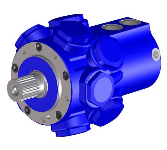

1 Hydraulic Motors Radial Piston Motors Precision drives with fixed displacement RM 80N... - RM 250N... series Vg = 80 ccm/rev ccm/ccm Repair Manual Doc.-No. HM3-013 UK
2 Seite 2 Table of contents 1. General Dismantling the distributor parts Dismantling the drive unit parts Removal of stuffing Setting the taper roller bearings Assembly the drive unit parts Assembly the distributor parts Measurement and adjustment table Starting-up Radial Piston Motor with 2nd shaft end (instrument shaft) Dismantling the instrument shaft- distributor peg Assembly the instrument shaft- distributor peg...7
3 1. General Radial Piston Motor Seite For dismantling / assembly the highest possible degree of cleanliness must be ensu red. Do not use fibrous cleaning rags or cotton waste. Do not carry out works of this nature in workshops, where metal cutting or grinding work is carried out where there is excessive dust. 1.2 lf the motor is opened or disconnected from its inlet / outlet pipes the escaping oil must be collected. 1.3 Appropriate jacking of the motor facilitates dismantling. 1.4 Ensure that dismantled parts, in particular all sliding surfaces and sealing elements, are not contaminated or damaged. 1.5 A table covered with clean oiled paper is recommended for depositing dismantled parts. 1.6 Lifting gear is required. - RM 80N Kgs. up to RM 250N Kgs. 1.7 The following spares lists are in explanation to this repair manual: for RM 80N No. RM 50.79, for RM 125N No. RM 50.21, for RM 160N No. RM and for RM 250N No. RM Dismantling the distributor parts 2.1 Jack the motor in a vertical position with the driveshaft pointing downwards. 2.2 Remove the allen-type screws (45). 2.3 Remove the cover plate (47). 2.4 Remove lockwasher (43.7) using two strong screwdrivers, whereby the bush (46) must be depressed by approx. 1 mm, so that the lockwasher is free of axial pressure and can be eased out with two srcewdrivers. 2.5 The bush (46) can be extracted by fitting two M8 srews in the tapped holes provided and pulling the bush by the screws. The seals could be damaged and must in each case be replaced prior to fitting. 2.6 The pressure pad (43.2) with spring (44) and seals (56.1 and 56.2) is in most cases located centrally in the bush and is removed at the same time. Note: All faces of the interior, the bush and the pressure pad are sealing surfaces and must not show any scoring (do not damage). 2.7 Extract distributor eccentric (43.1) together with roller cage and cylindrical rollers. 2.8 Control inner ring (41.1) and control outer ring (42) with seals (55.1/55.21, 57.1/57.2), spring disk (43.4) and ball valve (41.2/41.3) to be removed completely. 2.9 Damage to the distributor (40) occurs only rarely. As special tools and experience is required, please return this item to our works for repair. 3. Dismantling the drive unit parts 3.1 Jack up the motor with driveshaft upward (collect leaking oil).
4 Seite Loosen and remove the bearing cover screw (26). Clean the screw thread from fixing adhesive Loctite or Omnifit (screws are glued). Torque as per table on page Evenly press out the bearing cover (21) by screwing two screws (26) into the opposite threaded holes. 3.4 The Shaft Seal (51.3) with wiper (51.1) can now be replaced and, if required, the spacer ring (51.2). 3.5 Now the stuffings have to be disassembled as per Remove the adapter plates (23). 3.7 The crankshaft (10) can now be removed vertically. For this purpose, an eyebolt as per table on page 9 is fitted into the thread on the crankshaft, by which the crankshaft is carefully extracted. When extracting the crankshaft (10), the polygonring (32) and the taper roller bearings will be removed together with the crankshaft. 4 Removal of Stuffing 4.1 Slacken and remove the stuffings (22), using a SW 70 hexagon ringspanner. Remove O-ring (54). 4.2 Remove disc spring (33) and spiral spring (34). 4.3 Do not mix up the pistons (31) vis-a-vis the motor housing bores, mark with remova ble paint, if required. 4.4 Manually remove piston (31) from bore. Replace sealing ring (59) at bottom of piston only if required. Remark: The outside diameter of the sealing washer (59) is larger than the diameter of the piston drill hole. For a proper mounting of this seal use a tube with a cone inside. 5. Setting the taper roller bearings 5.1 Before setting the taper roller bearings, disassemble the piston according to ( ) and draw out the crankshaft The setting of the taper roller bearings is carried out by selecting suitable alignment disc (23). The alignment disc consists layers of aluminium foil, glued to each other by adhesive. The bearing play of the taper roller bearings can be reduced by removing individual discs so that a higher frictioal torque is obtained at the crank shaft. 5.3 Insert the rear taper roller bearing (25) into the motor housing (20). Carefully insert the crankshaft into the rear taper roller bearing of the motor housing. Fit the front roller bearing (24) onto the crankshaft (10). Insert the alignment disc (23) into the motor housing and insert the bearing cover (21) over the crankshaft into the motor housing. Secure with 4 screws (26). Fit a hexagon head screw into the thread in the crankshaft. Apply a torque wrench and slowly rotate the crankshaft using the torque wrench. Do not lubricate bearing tracks. lf the bearings are set correctly, the torque wrench must show a torque as per table on page 9. The bearing play can be reduced by removing some of the foils from the alignment disc (23).
5 5.4 After setting the bearings, again dismantle the crankshaft. Seite 5 6. Assembly the drive unit parts Assembly is carried out in reverse order. 6.1 Fit taper roller bearing (25) into the motor housing. 6.2 Fit the crankshaft according to 3.6 in reverse order. 6.3 Fit the bearing (24) with the crankshaft. 6.4 Clean the threads in the motor case with a fat solvent and wet the first turns with Loctite or Omnifit. 6.5 Assemble the bearing cover (21) with O-ring (52) and alignment disc (23) as prepared under Check the shaft sealing ring. lf required, fit new shaft sealing ring (51.3) and new wiper (51.3) to the bearing cover (21). Do not forget the distance ring (51.2) between the shaft sealing ring (51.3) and the wiper ring (51.1). Note: Uniformly press in the shaft sealing ring on the circumference of the outer ring of the shaft sealing ring (if required, use suitable tube); twisting will destroy the shaft sealing ring. The spaces between the shaft sealing ring (51.3) and the wiper ring (51.1) and also under the shaft sealing ring (51.3) are to be filled with acid-free grease. 6.7 Fit the bearing cover (21) with outer race of the taper roller bearing (25) and shaft sealing ring (51.3), distance ring (51.2) and wiper ring (51.1). Avoid damage to the sealing lip. lf required, use protective sleeve. 6.8 Fit the allen-type screws (26). Uniformly tighten the screws of the bearing cover. Torque as per table on page The assembly of pistons and stuffings ensues in reverse order - see Assembly the distributor parts Assembly of the control unit in reverse order to dismantling - see Jack motor with the shaft end pointing downwards. 7.2 Renew all seals of the control unit. 7.3 Fit completely assembled control ring (items 41.1, 41.2, 41.3, 42, 55.1, 55.2, 57.1, 57.2) and according to 7.5 push eccentrically towards the centre axis. 7.4 Assemble the roller cage (43.5) with the eccentric (43.1). Assemble the cylindrical roller (43.6) in the cage (43.5). Push this assembled unit over the crankshaft. 7.5 Care should be taken when assembling the distributor eccentric (43.1), that the upmost point of the distributor eccentric is pushed upwards by 90 to the crankshaft eccentric, (10) to the left of the upmost point of the crankshaft eccentric on the square section of the crankshaft. The upmost point of the crankshaft eccentric is marked by means a punch mark on the face of the square sectionof the control spigot of the crankshaft (when viewed in the direction of the distributor).
6 Seite 6 This method of assembly of the distri butor provides right-hand rotation, with the flow passing from port 2 to 1. (See catalogue sheet for further details). 7.6 Determination of the upmost point of the distributor eccentric. Upmost point of the crankshaft eccentric Upmost point of the distributor eccentric Upmost point of the control spigot 7.7 Determination of the upmost point of the crankshaft eccentric. 7.8 In the case of all motors with a splined shaft a punch mark on the face of the take-off shaft points in the direction of the upmost point of the eccentric on the crankshaft (10). Eccentric direction when viewed from the shaft end. Motos with splined shaft and involute splined shaft (acc. DIN 5480) Motors with cylindrical shaft with key acc. DIN 6885 Punch mark At the motor with cylindrical drive shaft, type Z, the feather key lies on the drive shaft and opposite to the eccentric peask point of the crankshaft (10). 8. Measurement and adjustment table Torque [Nm] RM 80N RM 125N RM 160N RM 250N Remarks Screws (26) Bearing cover Plugs (22) Plugs Screws (45) End cover Bearing setting 0,5-2,5 0,5-2,5 0,5-2,5 0,5-2,5 Threaded hole Crankshaft / hollow shaft M 16 (M 10) M 16 (M 10) M 16 (M 10) M 16 (M 10) Final strength after Recommended self-hardening plastics: Loctite 270 ~12 h Omnifit 80 M Rot ~24 h Eye bolt DIN 580 suitable for Transport 9. Starting-up 9.1 The motor leakage oil connection is to be positioned so that the casing always remains full of hydraulic fluid. 9.2 The motor must be filled with hydraulic fluid via a leakage fluid connection before starting-up.
7 Seite Leakage from the radial piston motor must be returned to the tank separately from runback and from other users, to avoid retained pressure. 9.4 The leakage pressure measured directly at the leakage fluid connection should not exceed 1 bar. 9.5 The entire hydraulic system should be completely vented to ensure faultless operation of the motor. 9.6 When starting-up the motor, do not operate immediately at maximum pressure and / or maximum speed, but allow newly fitted parts time to settle or run in. Recommendation for the first hours of operation: Pressure approx bar Speed approx rpm Optimum running properties only occur after a running-in phase of approx hours. 10. Radial Piston Motor with 2nd shaft end (instrument shaft) 10.1 The motor with instrument shaft is identified in the type designation by the prefix M Parts (43.3, 44, 45, 47, 49.1, 49.2, 49.3 and 63) are identical for all motors with instrument shaft from RM 80N... M, RM 125N... M, RM 160N... M, and RM 250N... M. 11. Dismantling the instrument shaft- distributor peg 11.1 The motor is placed on a stand with the take-off shaft pointing downwards The hexagon socket screws are removed from the end-cover (47) The end-cover (47) together with the shaft sealing ring (63) and the bearing (49.2) are withdrawn from the motor housing with the aid of an M6 tap Remove spring (44) and spring retainer (43.3) from the instrument shaft (49.1) Now dismantle the remaining components of the distributor assembly, given under 2.4 to Assembly of the intrument shaft- distributor peg 12.1 Procedure is the reverse sequence of that for dismantling, whereby all seals, and possibly the bearing (49.2) have to be replaced The instrument shaft (49.1) is shrink-fitted into the crankshaft (10) and additionally secu red by means of a pin (49.3) In the event of replacement, a crankshaft (10) together with instrument shaft (49.1), should be ordered as a complete unit, or the detailed assembly instructions for the crankshaft-instrument shaft should be ordered.


 Offshore technology Printing and")

8 DUESTERLOH has been developing fluid technology products for more than 100 years. The drives, controls and hydraulic power units from Hattingen are appreciated throughout the world for their complete reliability; including under extreme conditions. The owner-managed company s own development and construction department and the wide range of products cater for distinctive flexibility and customer-orientation. Products Hydraulic radial piston motors Hydraulic axial piston motors Hydraulic high precision motors Pneumatic motors Pneumatic starters Hydraulic and pneumatic controls Hydraulic power units Designing controls and hydraulic power units specific to the customer is our company s major strength. Vast product diversity is also available for standardized products. Industrial areas of application Machine tools Smelting and rolling mill equipment Foundry machines Testing machines Shipbuilding (diesel engines) Offshore technology Printing and paper technology Vehicle construction Manipulators Environmental technology Mining equipment Materials handling equipment Düsterloh Fluidtechnik GmbH Im Vogelsang 105 D Hattingen Tel.: Fax: info@duesterloh.de Internet: Certified acc. to ISO 9001
Hydraulic Motors. Radial Piston Motors with fixed displacement Series RM...X Vg = 250 cm³/u cm³/u. Repair manual. Doc.-No.
 Hydraulic Motors Radial Piston Motors with fixed displacement Series RM...X Vg = 250 cm³/u - 900 cm³/u Doc.-No. HM3-005 UK Seite 2 Table of contents 1. General... 3 2. Dismantling the distributor unit...
Multiple disc brakes. pressure released and spring operated multiple disc brakes series LBD T brake. Installation- operating instructions
 Multiple disc brakes pressure released and spring series LBD T brake = 50 Nm - 6300 Nm for dry or wet operation as well as for hardly combustible hydraulic fluids HFA, HFB, HFC and HFD Installation- operating
Pneumatic-Motors Accessories catalog DMO - PMW pneumatic gearwheel motors and spur gear motors
 Pneumatic-Motors Accessories catalog DMO - PMW pneumatic gearwheel motors and spur gear motors Dok.-Nr. M1-009 UK Contents accessories catalog Page 2 Designation... page Contents... 02 Ball valve PN 25...
HYDRAULIC-MOTORS. Radial Piston Motors with fixed displacement RM...X series V g = 250 cm 3 /rev cm 3 /rev
 s with fixed displacement RM...X series V g = 250 cm 3 /rev - 900 cm 3 /rev HYDRAULIC-MOTORS Catalogue No. HM1-015E RM 250X - RM 900X Page 2 Features: many displacements for all applications very high
Pneumatic Motors. Pneumatic Motors PMW PMW 530. Installation- operating instructions. Katalog-Nr.: A UK
 Pneumatic Motors Pneumatic Motors PMW 160 - PMW 530 Installation- operating instructions Katalog-Nr.: Contents PMW 160 - PMW 530 Page 2 Contents Designation... Page Transportation- and storing instructions...
Hydraulic Rotary Hammer Drill
 M a s c h i n e n f a b r i k G m b H Hydraulic Rotary Hammer Drill Type 2 2406 0010 Techn. Doc. No. 262 Illustration can differ from the original Repair Manual and Spare Parts List 224060010_Inst_en_Version_06.doc
Drive pinion and ring gear,
 Page 1 of 38 39-166 Drive pinion and ring gear, adjusting General notes: Drive pinion and ring gear must be very carefully adjusted to ensure long service life and smooth running. At the factory, drive
Standard Parts for Mould Making
 Standard Parts for Mould Making Index Your Production Partner 4-5 Guide Elements Locating units, round 8 Locating units, flat 8 Compensation Discs 9 Adjusting washers 9 Ejector rods 10 Centering sleeves
Dismantling and assembling transmission
 27-640 Dismantling and assembling transmission Operation number of the operation texts and work units or standard texts and flat rates: 27-4010 P27-5367-61 Control pressure cable (98) Slacken, remove and
Repair Manual and Spare Parts List
 Pneumatic Drive Unit Type Techn. Doc. No. 352 and Accessories for Pipe Cutting Machine Darstellung kann vom Original abweichen Repair Manual and 580027000_Inst_en_Version_02 Repair General In general,
Repair Manual and Spare Parts List
 Hydraulic Drive Unit Type Techn. Doc. No. 362 and Accessories for Pipe Cutting Machine Darstellung kann vom Original abweichen Repair Manual and 580067000_Inst_en_Version_03 Repair General In general,
SAI GM Series Piston Hydraulic Motor Crankshaft Design Radial Piston Motors
 SAI GM Series Piston Hydraulic Motor Crankshaft Design Radial Piston Motors www.chinawinches.cn (Dimension: inch) Brief Performance Table of Sai GM Series Piston Hydraulic Motor (Full range GM05- GM9 series)
Maintenance Instructions
 General Note These instructions contain information common to more than one model of Bevel Gear Drive. To simplify reading, similar models have been grouped as follows: GROUP 1 Models 11, 0, 1,, (illustrated),,
Pneumatic Angle Grinder also for Underwater Use Type
 M a s c h i n e n f a b r i k G m b H Pneumatic Angle Grinder also for Underwater Use Type 1 4311 0050 Illustration can differ from the original Repair Manual and Spare Parts List Compiled: 22.06.11 143110050_Inst_en_Version_00
GROUP 9 BOOM, ARM AND BUCKET CYLINDER
 GROUP 9 BOOM, ARM AND BUCKET CYLINDER 1. REMOVAL AND INSTALL 1) BUCKET CYLINDER (1) Removal Expand the arm and bucket fully, lower the work equipment to the ground and stop the engine. Operate the control
1988 Chevrolet Pickup V SUSPENSION - FRONT (4WD)' 'Front Suspension - "V" Series 1988 SUSPENSION - FRONT (4WD) Front Suspension - "V" Series
' 'Front Suspension - V Series 1988 SUSPENSION - FRONT (4WD) Front Suspension - V Series") 1988 SUSPENSION - FRONT (4WD) Front Suspension - "V" Series DESCRIPTION NOTE: Vehicle serial numbers used in this article has been abbreviated for common reference to Chevrolet and GMC models. Chevrolet
1988 SUSPENSION - FRONT (4WD) Front Suspension - "V" Series DESCRIPTION NOTE: Vehicle serial numbers used in this article has been abbreviated for common reference to Chevrolet and GMC models. Chevrolet
1984 Dodge W250 PICKUP
 1984 Dodge W250 PICKUP Submodel: Engine Type: V8 Liters: 5.2 Fuel Delivery: CARB Fuel: GAS Dana 44 MODELS THROUGH 1984 2. Raise and safely support the vehicle, then remove the wheel hub and bearings as
General repair instructions
 Page 1 of 10 00-10 The maximum possible care, cleanliness and proper tools are essential to ensure satisfactory and successful transmission repairs. The usual basic safety precautions also apply when carrying
Husqvarna Hedgetrimmers 325HS/ 325HE/ 325HDA. Workshop manual
 Husqvarna Hedgetrimmers 325HS/ 325HE/ 325HDA Workshop manual 101 90 73-26 2 Workshop Manual Hedge trimmers Supplement for models 325HS, 325HE,325HDA Contents 1. Starter 5 2. Ignition system 7 3. Fuel system
MANUAL TRANSAXLE Return to Main Table of Contents
 MANUAL TRANSAXLE Return to Main Table of Contents GENERAL... 2 MANUAL TRANSAXLE CONTROL... 12 SHIFT LEVER ASSEMBLY... 14 MANUAL TRANSAXLE... 15 MANUAL TRANSAXLE ASSEMBLY... 17 FIFTH SPEED SYNCHRONIZER
REEDSTER 125cc. versions: F1 - F2 - F3 - F4 OVERHAULING MANUAL
 REEDSTER 125cc versions: F1 - F2 - F3 - F4 OVERHAULING MANUAL 07/11/07 21/01/2009 1 INDEX Page 1. - REEDSTER 125cc ENGINE DISASSEMBLY 1 2. - CRANKSHAFT DISASSEMBLY / ASSEMBLY 13 2.1 - CRANKSHAFT DISASSEMBLY
INSTALLATION, OPERATION AND MAINTENANCE MANUAL FOR T40 Mk. 2 DISC BRAKE CALIPER M1492
 INSTALLATION, OPERATION AND MAINTENANCE MANUAL FOR T40 Mk. 2 DISC BRAKE CALIPER AMENDMENT AND ISSUE RECORD Amendment Number Issue Date Issued by - 01 A.D. (i) INDEX PAGE 1 Installation 1 1.1 General description
Hydraulic Angle Grinder for Underwater Use Type
 M a s c h i n e n f a b r i k G m b H Hydraulic Angle Grinder for Underwater Use Type 1 1585 0010 Illustration can differ from the original Repair Manual and Spare Parts List Compiled: 18.01.13 115850010_Inst_en_Version_03
ORIGA SYSTEM PLUS Guides, Brakes and Valves for Modular Linear Drive Systems OSP Appendix to the Operating Instructions
 ORIGA SYSTEM PLUS Guides, Brakes and Valves for Modular Linear Drive Systems OSP Appendix to the Operating Instructions TAll personnel who have anything to do with the OSP fitted with guides, brakes or
Oil pan, oil strainer and valve body, removing and installing
 Page 1 of 44 38-1 Oil pan, oil strainer and valve body, removing and installing WARNING! Do not run engine with the oil pan removed or without ATF filling and do not tow vehicle. Notes: Always replace
INSTRUCTION MANUAL AND PARTS LIST FOR SERIES 8L-630J AND 630M WARNING
 INSTRUCTION MANUAL AND PARTS LIST FOR SERIES 8L-630J AND 630M WARNING READ CA-l AND TIDS INSTRUCTION MANUAL PRIOR TO INSTALLATION, OPERATION OR MAINTENANCE WARNING This Instruction Manual and General Instructions
25-1 PROPELLER SHAFT CONTENTS GENERAL INFORMATION... 2 SEALANT... 2 SERVICE SPECIFICATIONS... 2 SPECIAL TOOL... 2 LUBRICANT... 2 PROPELLER SHAFT...
 25-1 PROPELLER SHAFT CONTENTS GENERAL INFORMATION... 2 SERVICE SPECIFICATIONS... 2 LUBRICANT... 2 SEALANT... 2 SPECIAL TOOL... 2 PROPELLER SHAFT... 3 25-2 PROPELLER SHAFT - General Information/Service
Final drive gear set, recommended sequence for adjusting
 Page 1 of 31 39-148 Final drive gear set, recommended sequence for adjusting If the pinion shaft and ring gear have to be readjusted, the following sequence is recommended for maximum efficiency: 1.) Determine
Technical Description Edition 2007 Mounting, maintenance and repair of propshafts with flanged universal joints
 Technical Description Edition 2007 Mounting, maintenance and repair of propshafts with flanged universal joints 1. Recommendations Assembly, disassembly, maintenance and repair of propshafts should be
Operating and Maintenance Instructions. Abteilung TB, Schell Seite 1 8 SERIES 56
 Abteilung TB, Schell Seite 1 8 These instructions supersede all earlier instructions, in particular BWS 109-0 till BWS 109-3. For applications in areas with explosion hazard it is obligatory to observe
TRANSMISSION 6.7 GENERAL HOME. See Figure The transmission is a five-speed constantmesh type housed in an extension of the crankcase.
 TRANSMISSION 6.7 GENERAL See Figure 6-45. The transmission is a five-speed constantmesh type housed in an extension of the crankcase. Mainshaft Neutral Mainshaft st Gear b06x6x Countershaft 4 Out 5 Countershaft
FRICTIONAL CONNECTIONS CATALOGUE
 FRICTIONAL CONNECTIONS CATALOGUE Reprinting and all other forms of copying, not even partially, is prohibited without permission from Stüwe. Maschinenfabrik GmbH & Co. KG Production: Studio Salewski GmbH,
Pull out clutch E snap ring and withdraw complete clutch pack of clutch E. 6 HP 26 ZF Getriebe GmbH Saarbrücken CD
 Press down cup spring in the mandrel press with assembly bracket 5x46 002 566 and remove snap ring with suitable pliers. Take out planet carrier and cup spring. Take the O-ring seal off the planet carrier.
Type 2000, 2002, 2012
 Replacement of valve and seal set Conversion of control function Service Manual We reserve the right to make technical changes without notice. Technische Änderungen vorbehalten. Sous réserve de modifications
2006 MINI Cooper SUSPENSION Wheels & Tires - Repair Instructions - Cooper (1.6L) R50/W10 & Cooper S
 R50/W10 & Cooper S") WHEELS 2002-05 SUSPENSION Wheels & Tires - Repair Instructions - Cooper (1.6L) R50/W10 & Cooper S 36 10 300 REMOVING OR INSTALLING FRONT OR REAR WHEEL NOTE: For Special Tool identification, see WHEEL AND
WHEELS 2002-05 SUSPENSION Wheels & Tires - Repair Instructions - Cooper (1.6L) R50/W10 & Cooper S 36 10 300 REMOVING OR INSTALLING FRONT OR REAR WHEEL NOTE: For Special Tool identification, see WHEEL AND
T-400 Portable Irrigation Machine Maintenance & Repair Manual
 T-400 Portable Irrigation Machine Maintenance & Repair Manual A. Inspection of external leakage 1. Deep - groove ball bearing and rotary shaft lip seal on turbine shaft 1.1 Leakage on relief well In
Mechanical Sliding Caliper Disc Brake. Type PAN 19-1 Assembly and Maintenance Instructions
 WABCO Mannheim Mechanical Sliding Caliper Disc Brake Type PAN 19-1 Assembly and Maintenance Instructions WABCO Radbremsen GmbH Postfach 71 02 63 D-68222 Mannheim Bärlochweg 25 D-68229 Mannheim +49 (0)6
disc brake axle with WABCO calipers
 1 2 disc brake axle with WABCO calipers 3 4 disc brake axle with WABCO calipers 5 6 disc brake axle with WABCO calipers IMT axles are supplied as non-cambered and are within the limits of a 2 minute negative
MANUAL INDEX. Page 1. LEOPARD 125cc ENGINE DISASSEMBLY CRANKSHAFT DISASSEMBLY/ ASSEMBLY CRANKSHAFT DISASSEMBLY 8
 MANUAL INDEX Page 1. LEOPARD 125cc ENGINE DISASSEMBLY 1 2. - CRANKSHAFT DISASSEMBLY/ ASSEMBLY 8 2.1- CRANKSHAFT DISASSEMBLY 8 2.2- CRANKSHAFT ASSEMBLY 10 3. LEOPARD 125cc ASSEMBLY 13 4. - CHECK CYLINDER
Front Hub and Disc (4WD Model)
") 4C 8 DRIVE SHAFT SYSTEM Disassembled View Front Hub and Disc (4WD Model) 411RW001 Legend (1) Bolt (2) Cap (3) Snap Ring and Shim (4) Hub Flange (5) Lock Washer and Lock Screw (6) Hub Nut (7) Outer Bearing
4C 8 DRIVE SHAFT SYSTEM Disassembled View Front Hub and Disc (4WD Model) 411RW001 Legend (1) Bolt (2) Cap (3) Snap Ring and Shim (4) Hub Flange (5) Lock Washer and Lock Screw (6) Hub Nut (7) Outer Bearing
1. General Description
 General Description 1. General Description A: SPECIFICATION Front Rear Model Wheel arch height (Tolerance: +12 mm 24 mm ( +0.47 in 0.94 in)) mm (in) 376 (14.8) Camber (Tolerance: 0 45 Differences between
Bearing Handling. 15. Bearing Handling Bearing storage Installation
 15. Bearing Handling Bearings are precision parts and, in order to preserve their accuracy and reliability, care must be exercised in their handling. In particular, bearing cleanliness must be maintained,
BOTTOM END SERVICE TOOLS SERVICE PRODUCTS ENGINE, CVT AND GEARBOX Subsection 10 (BOTTOM END)
") BOTTOM END SERVICE TOOLS Description Part Number Page CRANKCASE SUPPORT MAG/PTO... 529 036 031... 151 CRANKSHAFT LOCKING BOLT... 529 035 617... 154 DRIVE SHAFT OIL SEAL INSTALLER... 529 036 028... 143
BOTTOM END SERVICE TOOLS Description Part Number Page CRANKCASE SUPPORT MAG/PTO... 529 036 031... 151 CRANKSHAFT LOCKING BOLT... 529 035 617... 154 DRIVE SHAFT OIL SEAL INSTALLER... 529 036 028... 143
FRONT AXLE AND SUSPENSION FA 1
 FRONT AXLE AND SUSPENSION FA1 FRONT AXLE AND SUSPENSION FA2 FRONT AXLE AND SUSPENSION Troubleshooting TROUBLESHOOTING Problem Possible cause Remedy Page Wanders/pulls Tires worn or improperly inflated
REPAIR MANUAL 5 HP - 30 ZF GETRIEBE GMBH SAARBRÜCKEN
 REPAIR MANUAL 5 HP - 30 ZF GETRIEBE GMBH SAARBRÜCKEN Impressum: Verantwortlich für den Inhalt Abteilung MKTD, ZF Getriebe GmbH, Saarbrücken Druck: HAGER PAPPRINT GmbH, Gedruckt in der BRD Published by
BRAKE E
 8-1 GENERAL...8-2 SPECIFICATIONS...8-6 COMPONENTS...8-7 FRONT BRAKE...8-12 DISASSEMBLY INSPECTION REASSEMBLY (Pn1, Cu2 3 TON SERIES)...8-12 DISASSEMBLY INSPECTION REASSEMBLY (Pn2 3 TON SERIES)...8-17 BRAKE
Engine Dismantle and Assemble ( )
") Engine Dismantle and Assemble ( 34 8) Special Tools 5 053 Slide hammer 47 Vibration damper remover 47 5053 00 Splined head socket, cylinder head bolts 87 Mounting stand with geared drive 00 059C Installer
Engine Dismantle and Assemble ( 34 8) Special Tools 5 053 Slide hammer 47 Vibration damper remover 47 5053 00 Splined head socket, cylinder head bolts 87 Mounting stand with geared drive 00 059C Installer
Maintenance Information
 45528270 Edition 1 June 2007 Barring Motor T480 Series Maintenance Information Save These Instructions WARNING Always wear eye protection when operating or performing maintenance on this Barring Motor.
CHAPTER 7 TRANSMISSION (MFO6S)
") 1 page INDEX1 Model SG1J (MF06S) TRANSMISSION 7-1 7-142E-07 CHAPTER 7 TRANSMISSION (MFO6S) Model SG1J 1 Models FE, FF and SG2J 1 Model FD 7 TROUBLESHOOTING...7-2 SPECIAL TOOLS...7-5 REMOVAL...7-7 GEAR
1 page INDEX1 Model SG1J (MF06S) TRANSMISSION 7-1 7-142E-07 CHAPTER 7 TRANSMISSION (MFO6S) Model SG1J 1 Models FE, FF and SG2J 1 Model FD 7 TROUBLESHOOTING...7-2 SPECIAL TOOLS...7-5 REMOVAL...7-7 GEAR
Engine Dismantle and Assemble ( )
") Engine Dismantle and Assemble (2 34 8) Special Tools 2-036A Remover for pilot bearing 2-37 Oil seal installer/aligner 237 2036A 2-044A Installer/Aligner, Pilot Bearing/Clutch Plate 244 2-44 Inlet manifold
Engine Dismantle and Assemble (2 34 8) Special Tools 2-036A Remover for pilot bearing 2-37 Oil seal installer/aligner 237 2036A 2-044A Installer/Aligner, Pilot Bearing/Clutch Plate 244 2-44 Inlet manifold
TABLE OF CONTENTS 0 FRONT DRIVE , WHEEL HUB , WHEEL HUB BEARING , KNUCKLE
 Subsection 01 (TABLE OF CONTENTS) TABLE OF CONTENTS 0 FRONT DRIVE... 06-02-1 1, WHEEL HUB... 06-02-2 2, WHEEL HUB BEARING... 06-02-2, KNUCKLE... 06-02- FINAL DRIVE... 06-0-1 1, DRIVE CHAIN... 06-0-2 2,
REPAIR INSTRUCTION - MP4120-SWS/MP4124-SWS
 Disassembly sequence REPAIR INSTRUCTION - MP4120-SWS/MP4124-SWS 1. With a 27mm wrench, remove the three discharge plugs (#48) and three inlet plugs (#42A) from the manifold (#43). 2. Inspect the plug o-rings
Valvetrain, servicing
 Page 1 of 51 15-32 Valvetrain, servicing Note: Cylinder heads with small cracks between the valve seats that are less than 0.3 mm (0.012 in.) wide and/or between one valve seat and only the first 4 threads
Installation and Operating Instructions for EAS -NC clutch Type 45_. _. _ Sizes 02 and 03
 Table of contents: Please read and observe this Operating Instruction carefully! A possible malfunction or failure of the clutch and any damage may be caused by not observing it. Page 1: - Table of contents
Rotary Valve Maxflo + 60 and 80 Opening type NT
 Rotary Valve Maxflo + 60 and 80 Opening type NT TECHNICAL MANUAL 1- INSTALLATION 1.1 - Valve pipe-work layout 1.2 - Specification check 1.3 - Installing the valve in the piping 1.4 - Connection to control
AUTOMATIC TRANSAXLE AUTOMATIC TRANSAXLE SYSTEM... COMPONENT PARTS...
 SYSTEM....... COMPONENT PARTS.................... OIL PUMP.............................. DIRECT CLUTCH........................ FORWARD CLUTCH..................... SECOND BRAKE........................ UNDERDRIVE
DRIVE AXLE Nissan 240SX DESCRIPTION & OPERATION AXLE RATIO & IDENTIFICATION AXLE SHAFT & BEARING R & I DRIVE SHAFT R & I
 DRIVE AXLE 1990 Nissan 240SX 1990 DRIVE AXLES Rear Axle - R200 240SX, 300ZX DESCRIPTION & OPERATION The axle assembly is a hypoid type gear with integral carrier housing. The pinion bearing preload adjustment
REPAIR MANUAL. Version 02/11/01 CD ZF GETRIEBE GMBH SAARBRÜCKEN
 REPAIR MANUAL 6 HP-26 Version CD ZF GETRIEBE GMBH SAARBRÜCKEN subject to alterations Copyright 2002 all rights reserved and published by ZF Getriebe GmbH, Saarbrücken, Department MKTD No part of this manual
HKS 700E. Service Manual June Ver. 2.04
 HKS 700E Service Manual 009 June Ver..04 HKS CO.,LTD 78 KITAYAMA FUJINOMIYA SHIZUOKA JAPAN 48-09 TEL +8(0)544-54-78 FAX +8(0)544-54-40 hks_aviation@hks-power.co.jp http://www.hks-power.co.jp/hks_aviation/
REPAIR MANUAL. W 390 MS torque converter a
 REPAIR MANUAL W 390 MS 449 75 606a Subject to technical changes Copyright by ZF This documentation is protected by copyright. Any reproduction and dissemination in whatever form also in adapted, paraphrased
TRANSMISSION 6.7 GENERAL HOME. See Figure The transmission is a five-speed constantmesh type housed in an extension of the crankcase.
 TRANSMISSION 6.7 GENERAL See Figure 6-46. The transmission is a five-speed constantmesh type housed in an extension of the crankcase. b06x6x Neutral st Gear Mainshaft Mainshaft 4 5 4 5 Countershaft Out
Front Fork Disassembling and Assembling RM-Z250L6. KAYABA Pneumatic Spring Front Fork PSF2
 Front Fork Disassembling and Assembling RM-Z250L6 KAYABA Pneumatic Spring Front Fork PSF2 RM-Z250L6 Front Fork Disassembling 1. Release air Release the air pressure by pressing the air valve with a screwdriver.
Hydraulic Reciprocating Saw
 Hydraulic Reciprocating Saw Type 5 1220 0050 Darstellung kann vom Original abweichen Repair Manual and Spare Parts List Compiled: 29.04.11 www.csunitec.com Page 1 of 16 REPAIR INSTRUCTION Do not disassemble
PACKING, HANDLING, TRANSPORTING AND STORING MOTORS
 PACKING, HANDLING, TRANSPORTING AND STORING MOTORS Make sure that the shaft of the motor is not loaded in any way and is protected from knocks. Axial loads or shocks may easily damage the bearings inside
MULTI CROSS RILLO. Highly flexible tyre coupling with taper bushings
 MULTI CROSS RILLO Highly flexible tyre coupling with taper bushings Maschinenfabrik Dipl.-Ing. Herwarth Reich GmbH Vierhausstr. 53 D-44807 Bochum P.O. Box 10 20 66 D-44720 Bochum Tel.: +49 / (0)234 / 959
Accessories, spare parts and measuring equipment
 Accessories, spare parts and measuring equipment The broad range of accessories, spare parts and measuring equipment represents a useful addition to the range of actual clamping tools and offers spare
5-3. ENGINE BOTTOM END
 BOTTOM END ENGINE DRIVE SHAFT 5-3-1 CRANKCASE Remover: 560012 Installer: 560011 Remover: 560014 Installer: 560013 CRANKSHAFT 5-3-2 WATER PUMP, OIL PUMP Installer: 560025 Remover: 560024 Installer: 560003
Assembly of the spring roller bracket
 Assembly of the spring roller bracket Table of content 1 ProtoMat S63/S103... 2 1.1. Subassembly of the spring roller bracket S63/S103... 2 1.1.1. Assembly steps and pre-adjustment... 2 1.2. Assembly of
Servicing front brakes
 46-1 Servicing front brakes C54 brake caliper, servicing Special tools and workshop equipment required VAG 1331 Torque wrench (or equivalent) VAG 1410 Torque wrench (or equivalent) VAG 1869/2 Brake pedal
Amarillo PUMP DRIVES (250 HP THROUGH 350 HP) INSTRUCTIONS FOR REPAIRING MODELS 250, 300, and 350
 INSTRUCTIONS FOR REPAIRING MODELS 250, 300, and 350") Amarillo PUMP DRIVES (250 HP THROUGH 350 HP) INSTRUCTIONS FOR REPAIRING MODELS 250, 300, and 350 Amarillo Right Angle Pump Drives, if properly installed and maintained, should provide years of service
Amarillo PUMP DRIVES (250 HP THROUGH 350 HP) INSTRUCTIONS FOR REPAIRING MODELS 250, 300, and 350 Amarillo Right Angle Pump Drives, if properly installed and maintained, should provide years of service
15. Bearing Handling Storage Fitting A-97
 15. Bearing Handling Bearings are precision parts, and in order to preserve their accuracy and reliability, care must be exercised in their handling. In particular, bearing cleanliness must be maintained,
1. introduction 3 2. Wheel bearing special features 4 3. Wheel bearing units from an economical point of view 5
 Motor chassis Service Technical BROCHuRE Wheel Bearing Repair Solutions for Light Commercial Vehicles CONTENT 1. introduction 3 2. Wheel bearing special features 4 3. Wheel bearing units from an economical
SECTION 5B MANUAL TRANSMISSION TABLE OF CONTENTS
 SECTION 5B MANUAL TRANSMISSION TABLE OF CONTENTS General Description and Operation... 5B-2 Shift Lever... 5B-2 Transmission Assembly... 5B-2 Specifications... 5B-3 Diagnostic Information and Procedures...
HGM-E LSHT Wheel Motor Service and Repair Manual
 HGM-E LSHT Wheel Motor Service and Repair Manual BLN-52198 January 2018 Table Of Contents Foreword... 1 How to use this manual... 2 General Instructions... 2 General Description... 2 Tools... 3 Torques...
Guides, Brakes and Valves
 Guides, Brakes and Valves Operating Instructions ORIGA SYSTEM PLUS Appendix to the Operating Instructions OSP-P / OSP-E Guides, Brakes and Valves OSP-P / OSP-E Content 1 Foreword to the Operating Instructions
Maintenance Information
 Form 16573321 Edition 1 July 2004 Air Grinder Series 61H Maintenance Information Save These Instructions Always wear eye protection when operating or performing maintenance on this tool. Always turn off
Pneumatic Axial Die Grinder also for Underwater Use Type , 0050
 M a s c h i n e n f a b r i k G m b H Pneumatic Axial Die Grinder also for Underwater Use Type 1 5077 0010 0020, 0050 Illustration can differ from the original Repair Manual and Compiled: 18.07.11 150770010_0020_0050_Inst_en_Version_00
SUSPENSION AND AXLE SA 1 SUSPENSION AND AXLE
 SA1 SA2 Troubleshooting TROUBLESHOOTING Problem Possible cause Remedy Front Page Rear Wanders/pulls Tires worn or improperly inflated Wheel alignment incorrect Hub bearing worn Front or rear suspension
FRP Ball Valves INSTALLATION & MAINTENANCE MANUAL
 FRP Ball Valves INSTALLATION & MAINTENANCE MANUAL FRP BALL VALVES TABLE OF CONTENTS MAINTENANCE AND INSTALLATION INSTRUCTIONS 1. 2. 2.1 2.2 2.3 2.4 GENERAL...Page 1 HANDLING...1 Receiving and Storing...1
Disassembling and assembling transmission
 27-640 Disassembling and assembling transmission Preceding work: Removing and installing transmission with torque converter (27-600). Operation number of operation texts and operation values or standard
4-50 BRAKES AND STEERING CLUTCHES
 4-50 BRAKES AND STEERING CLUTCHES Disassembly of bevel gear crown WARNING Lift and handle all heavy items with a hoist of appropriate capacity. Make sure that all parts are held by appropriate slings and
OVERHAUL. 1. INSPECT 1ST GEAR THRUST CLEARANCE (a) Using a feeler gauge, measure the 1st gear thrust clearance.
 Using a feeler gauge, measure the 1st gear thrust clearance.") 41135 OVERHAUL 4108901 1. INSPECT 1ST GEAR THRUST CLEARANCE (a) Using a feeler gauge, measure the 1st gear thrust clearance. 0.10 0.40 mm (0.0039 0.0157 in.) C68252 2. INSPECT 2ND GEAR THRUST CLEARANCE
41135 OVERHAUL 4108901 1. INSPECT 1ST GEAR THRUST CLEARANCE (a) Using a feeler gauge, measure the 1st gear thrust clearance. 0.10 0.40 mm (0.0039 0.0157 in.) C68252 2. INSPECT 2ND GEAR THRUST CLEARANCE
SALES DIVISION NETWORK TECHNICAL INFORMATION WORKSHOP MANUAL MOTOR ENGINE
 SALES DIVISION NETWORK TECHNICAL INFORMATION WORKSHOP MANUAL MOTOR ENGINE CONTENTS CHARACTERISTICS... 5 Engine markings... 5 TIGHTENING TORQUES... 5 SPECIAL TOOLS... 6 IDENTIFICATION... 7 Differences between
Servicing the Tool. Service Kit SERVICE KIT. For all servicing we recommend the use of the service kit (part number (S)).
).") Servicing the Tool Service Kit For all servicing we recommend the use of the service kit (part number 07900-04750(S)). SERVICE KIT ITEM PART Nº DESCRIPTION Nº OFF ITEM PART Nº DESCRIPTION Nº OFF 07900-00002
Servicing the Tool Service Kit For all servicing we recommend the use of the service kit (part number 07900-04750(S)). SERVICE KIT ITEM PART Nº DESCRIPTION Nº OFF ITEM PART Nº DESCRIPTION Nº OFF 07900-00002
PAN 17 MECHANICAL SLIDING CALLIPER DISC BRAKE ASSEMBLY AND MAINTENANCE INSTRUCTIONS
 PAN 17 MECHANICAL SLIDING CALLIPER DISC BRAKE ASSEMBLY AND MAINTENANCE INSTRUCTIONS PAN 17 MECHANICAL SLIDING CALLIPER DISC BRAKE Assembly and Maintenance Instructions 2nd edition This publication is
OVERHAUL MANUAL 28/09/05 mod. A 1 MAN-044 ING
 OVERHAUL MANUAL 28/09/05 mod. A 1 INDEX Page 1. - PARILLA X30 125cc RL TaG ENGINE DISASSEMBY 1 2. - CRANKSHAFT DISASSEMBLY/ ASSEMBLY 10 2.1- CRANKSHAFT DISASSEMBLY 10 2.2- CRANKSHAFT ASSEMBLY 12 3. - PARILLA
Safety Precautions Certain service procedures may require the vehicle/machine to be disabled (wheels raised off ground, work function disconnected, et
 Service Manual ASM 3 1 -F11 F11-5 through -250 Catalog 9129 8205-02 Februari 2001, GB Safety Precautions Certain service procedures may require the vehicle/machine to be disabled (wheels raised off ground,
Installation and Operating Instruction for Brake Caliper HW 150 HFA and HW 180 HFA E e
 Installation and Operating Instruction for Brake Caliper HW 150 HFA and HW 180 HFA E 09.736e Schaberweg 30-38 Phone +49 6172 275-0 61348 Bad Homburg Fax +49 6172 275-275 Germany www.ringspann.com info@ringspann.com
Quick Reference Guide: Technical Data SAF-axles with air suspension system. IMS Limited
 Quick Reference Guide: Technical Data SAF-axles with air suspension system IMS Limited IMS Limited is a key distributor for a range of premium products aimed at the commercial vehicle market and is the
Guide units. For toolmaking, fixture manufacturing and machine engineering
 Guide units For toolmaking, fixture manufacturing and machine engineering Guide units in compliance with DIN, ISO and STEINEL standards or according to your specifications Guide pillars Guide and pillar
BRAKE SYSTEM Nissan 240SX DESCRIPTION BRAKE BLEEDING * PLEASE READ FIRST * BLEEDING PROCEDURES ADJUSTMENTS BRAKE PEDAL HEIGHT SPECS TABLE
 BRAKE SYSTEM 1990 Nissan 240SX 1990 BRAKE SYSTEMS Nissan Disc & Drum Axxess, Maxima, Pathfinder, Pickup, Pulsar NX, Sentra, Stanza, 240SX, 300ZX DESCRIPTION All brake systems are hydraulically operated
MA-CFB_BEARING /2014 RZR VZR TZR RER
 Belt Driven Centrifugal Fans with deep groove ball bearing, self-aligning bearing or swivel-joint roller bearing (Translation of the Original) MA-CFB_BEARING 4.3 /204 RZR VZR TZR RER Deep groove ball bearing
Pneumatic Corner Drill
 Maschinenfabrik GmbH Pneumatic Corner Drill Type 2 1602 0030 Illustration can differ from the original Operation and Maintenance Manual Compiled: 31.07.08 216020030_en.doc Page 1 of 12 TECHNICAL SPECIFICATION
6200 Series. Specifications. Fluid End Power End Models 6211, 6212, 6221, & 6222 Models 6241 & 6242 Part Material Part Material Part Material
 5.2018.12.i 6200 Series Specifications The Flomore 6200 Series Pump line consists of a series of basic pump options all developed from a modular power unit. All units are pneumatically driven positive
HYDRAULICS. TX420 & & lower. Hydraulic Tandem Pump Removal. 4. Remove the LH side panel (Fig. 0388).
.") TX420 & 425 240000299 & lower 4. Remove the LH side panel (Fig. 0388). Hydraulic Tandem Pump Removal Note: Cleanliness is a key factor in a successful repair of any hydraulic system. Thoroughly clean all
TX420 & 425 240000299 & lower 4. Remove the LH side panel (Fig. 0388). Hydraulic Tandem Pump Removal Note: Cleanliness is a key factor in a successful repair of any hydraulic system. Thoroughly clean all
I. TWO-STROKE MECHANICAL EN- GINE PARTS
 I. TWO-STROKE MECHANICAL EN- GINE PARTS 1. UNIBLOCK ENGINES (AV520-600-750-125) a) INTRODUCTION Fig. 1 shows the short block. Fig. 2 shows an exploded view of the engine. As may be seen the momoblock is
Transmission, disassembling and assembling
 Page 1 of 27 34-43 Transmission, disassembling and assembling Disassembly sequence Page 34-55. Transmission overview 1-1st gear 2-2nd gear 3-3rd gear 4-4th gear 5-5th gear 6 - Reverse gear Removing and
SECTION H STEERING. Section Description Page No. H.1 GENERAL DESCRIPTION 3 H.2 STEERING WHEEL 3 H.3 INNER COLUMN 5 H.
 SECTION H STEERING Section Description Page No. H.1 GENERAL DESCRIPTION 3 H.2 STEERING WHEEL 3 H.3 INNER COLUMN 5 H.4 OUTER COLUMN 5 H.5 STEERING UNIT LOCK STOPS 6 H.6 STEERING UNIT 6 H.7 STEERING ARMS
Char-Lynn Hydraulic Motor. Repair Information Series. April, 1997
 Char-Lynn Hydraulic Motor April, 1997 Repair Information Geroler Motors 002 00 004 Parts Drawing 1 See Note 2 Page 1 22 1 9 1-1/4 Split Flange Ports 8 7 6 5 B 1 See Note 2 Page 2 24 4 14 19 20 15 1 18
a. remove counterbalance valves, travel motors and travel drives
 * For further information, contact Caterpillar Service Technology Group. Start By: a. remove counterbalance valves, travel motors and travel drives 1. Remove the counterbalance valve. See, "Disassemble