DYNATECH PROGRESSIVE SAFETY GEAR PR-2500-UD (V.50)
|
|
|
- Elijah Newman
- 5 years ago
- Views:
Transcription
1 DYNATECH PROGRESSIVE SAFETY GEAR PR-2500-UD (V.50) INSTRUCTIONS FOR USE AND MAINTENANCE
2 - 1 -
3 - 2 -
4 - 3 -
5 - 4 -
6 - 5 -
7 - 6 -
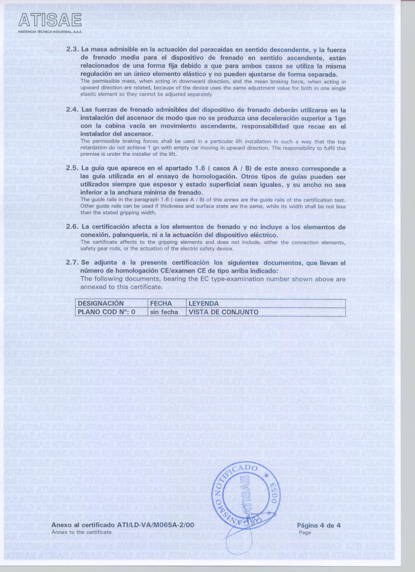
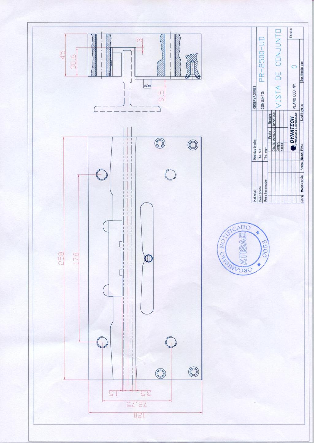
8 INSTRUCTIONS FOR USE AND MAINTENANCE 1. GENERAL INDICATIONS. 2. SAFETY GEAR INSTALLATION TO THE SLING MAKER TO THE INSTALLER. 3. USE AND MAINTENANCE. 3.1 GUIDE RAILS GUIDE RAILS WITH A GRIPPING WIDTH OF 25mm OR GREATER GUIDE RAILS WITH A GRIPPING WIDTH OF 20mm. 3.2 SPEED GOVERNOR. 3.3 RANGE OF USE GUIDE RAILS WITH A GRIPPING WIDTH OF 25mm OR GREATER GUIDE RAILS WITH A GRIPPING WIDTH OF 20mm. 3.4 FRICTION PARTS REPLACEMENT. 3.5 MAINTENANCE CLEANING CORROSION. 4. GENERAL DRAWING
9 1.-GENERAL INDICATIONS. Each supplied set of safety gears has been regulated at the factory according to the required use characteristics: Total weight (P+Q) and the guide rail thickness. These characteristics, the EC type examination number and the serial number are shown on the protection plates attached to the safety gear boxes. It is absolutely forbidden: a) To combine and install safety gear boxes with different serial numbers. b) To use a set of safety gears for installations with different characteristics to the ones shown on the protection plates of their safety gear sets. c) To intervene on any safety gear component. DYNATECH DYNAMICS & TECHNOLOGY, S.L. will not be responsible of any damages caused by the unobservance of any point of these general indications. 2.-SAFETY GEAR INSTALLATION. The Standard requires that the safety gear installation must be done including a security contact of type AC - 15 or DC - 13 according to EN TO THE SLING MAKER: The fixing holes for the safety gear must be made in the sling sides according to the dimensions and positions shown in the enclosed safety gear drawings, making sure the guide rail axis center to the sling beams
10 Once the safety gear is well placed and its roller trains are attached to the driving bars, it should be checked that both trains act synchronized in accordance to the driving bar commands. The sling maker is responsible for the proper location of the safety gear on the sling as well as the adjustment checking and synchronized working of the driving bar. The pin of the train, in its rest position, must be at the central point of the protection plates. Rest position - 9 -
11 Downwards engagement Upwards engagement
12 As a suggestion for the safety gear fixing to the sling, the tightening torque of 8.8 M12 screws is Nm and 111 Nm for those of Remark: The rollers for the downwards engagement marked with a D letter, must remain always at the lower part of the safety gear. The letters which rollers are distinguished with can be appreciated at first view trough the long hole of the protection plates TO THE INSTALLER: During the installation at the well, first of all, the guide rails must be introduced in the grooves of the safety gear housings. Then the position of the guide rail in the housing is adjusted as follows: the side of the guide rail, 1.5 mm from the brake block, the guide head, 3mm from the bottom of the groove (see drawings). For these adjustments the sliders will be handled without modifying the position of the safety gear in the sling because the sling maker
13 must have properly fixed the safety gear in its final position. For the correct safety gear acting, the distances mentioned here above must be strictly respected by the installer. To make easy the adjustment at work of the distances between the faces of the guide rails and the parts of the safety gears which are opposite the guide rail, it will be possible to use plates which will allow the emplacement of the guide rail in its correct position in the grooves of the safety gear. The plates must be removed once the adjustment operation has finished. Remark: The installer must be sure that the sling maker has situated the rollers for the downwards engagement, marked with a D letter, at the lower part of the safety gear
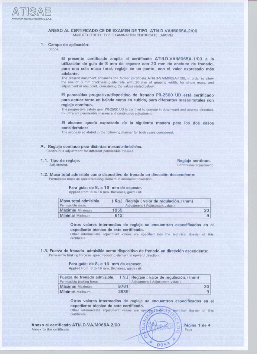
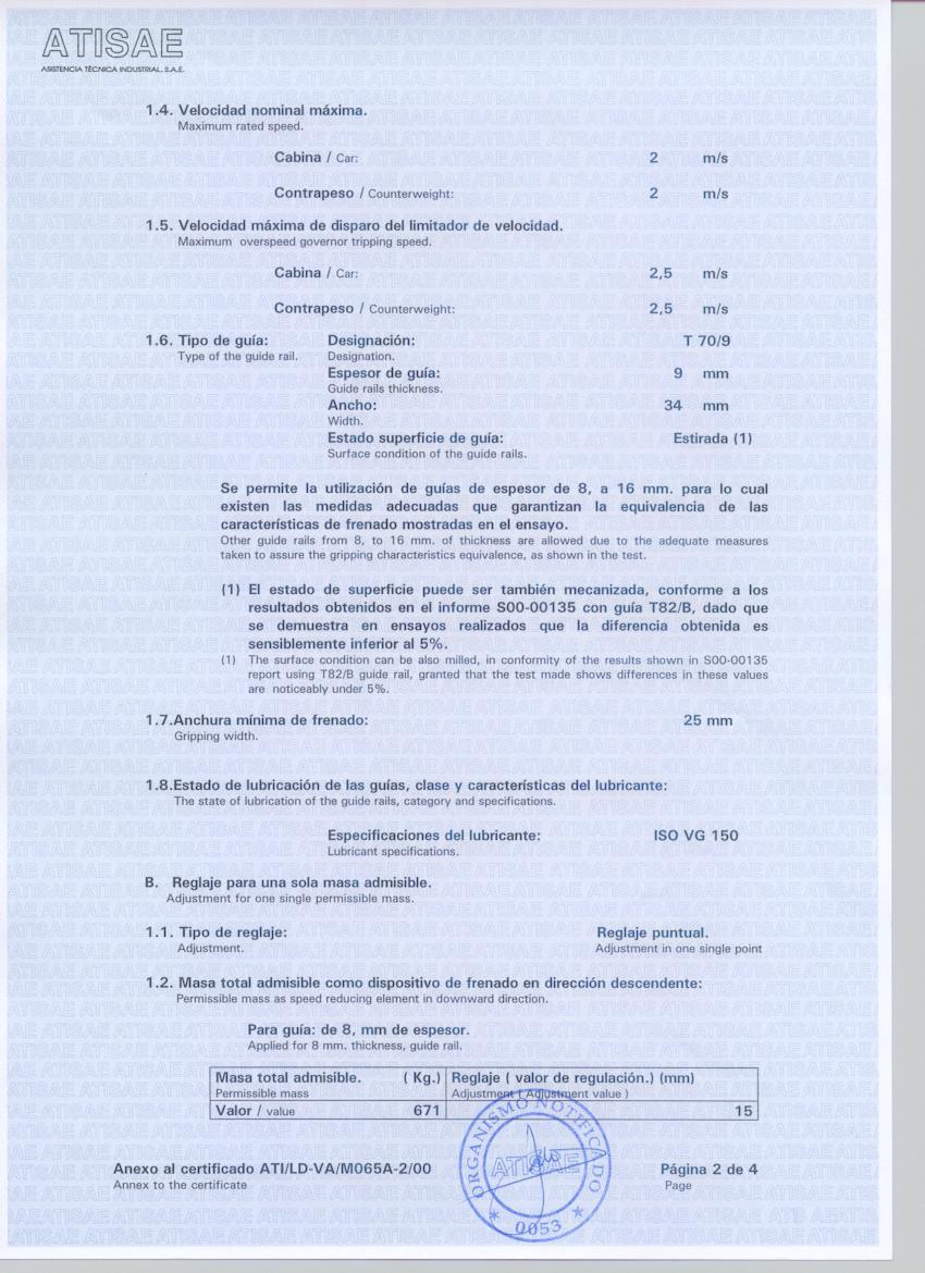
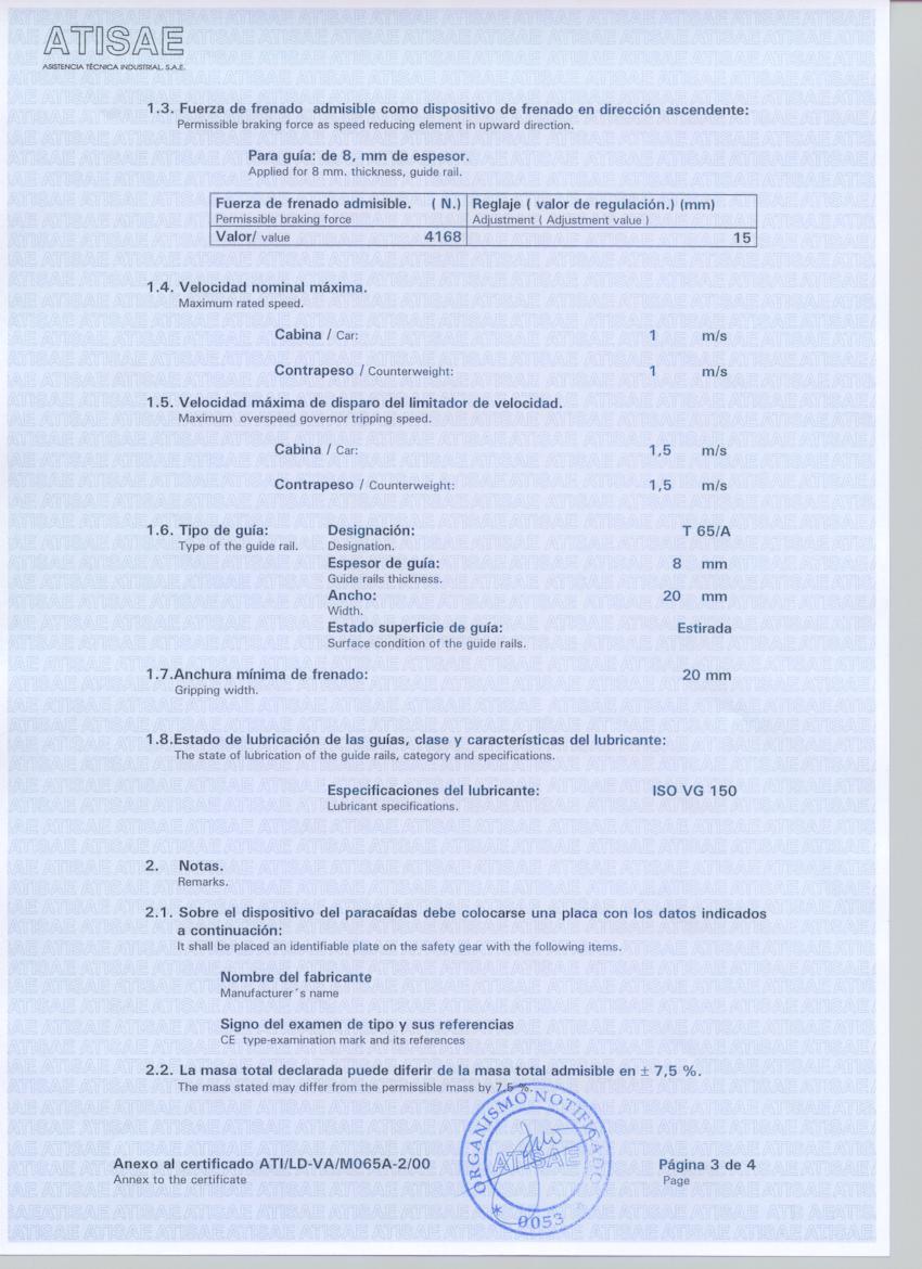
14 3.-USE AND MAINTENANCE. The non-fulfilment of the following prescriptions may produce deceleration values and breaking distances which could not be in accordance with the Standard. 3.1-GUIDE RAILS: GUIDE RAILS WITH A GRIPPING WIDTH OF 25mm OR GREATER. a) The guide rails used can be either the cold-drawn or the planed type. The admissible tolerances for the guide rails thickness are between 0 and mm. b) The progressive safety gear PR-2500-UD can be used with this type of guide rails until a nominal speed of 2m/s and the governor response maximum speed is 2.5 m/s. c) If after the safety gear performance you find scratched guide zones placed within a distance of less than 1 meter between them, it is recommended to substitute the affected guide parts. d) The guide rails must be lubricated with ISO VG 150 oil lubricant. e) Admissible widths of guiderail: 7 16 mm GUIDE RAILS WITH A GRIPPING WIDTH OF 20mm.(for example T 65/A) a) The guide rails used can be either the cold-drawn or the planed type. The admissible tolerances for the guide rails thickness are between 0 and mm. b) The progressive safety gear PR-2500-UD can be used with this type of guide rails until a nominal speed of 1m/s and the governor response maximum speed is 1.5 m/s
15 c) If after the safety gear performance you find scratched guide zones placed within a distance of less than 1 meter between them, it is recommended to substitute the affected guide parts. d) The guide rails must be lubricated with ISO VG 150 oil lubricant. 3.2-SPEED GOVERNOR: The speed governor rope tension has to be big enough to warrant, during the governor performance, a traction of 300 Nm at least in the connection point of the safety gear driving bar. 3.3-RANGE OF USE: GUIDE RAILS WITH A GRIPPING WIDTH OF 25mm OR GREATER. Here below the standard P+Q board is shown. The nominal values are those of the central line. -7'5% P+Q '5%
16 GUIDE RAILS WITH A GRIPPING WIDTH OF 20mm.(for example T 65/A) -7'5% 621 P+Q '5% FRICTION PARTS REPLACEMENT: The friction parts, brake shoes and rollers, can support three free fall upwards performances and three downwards performances, as it is exposed in the Standard EC typeexamination criteria. Anyway, after having intervene in a real situation it is recommended to replace the friction parts. In that case, contact Dynatech or its nearest distributor, in order to know the procedure to be followed. In order to obtain a better control, the maintenance person may have a register of the safety gear performances. The safety gear serial number should be written in its register as well as each and every acting. It is not necessary the braking parts replacement, caused by normal inspection tests, unless the braking distance surpass the double of the one obtained at the very first test of the installation
17 3.5-MAINTENANCE: CLEANING. It is very important to make sure that there is not any alien element inside the safety gear housing in order to guarantee the proper work of the moving parts CORROSION. Dynatech safety gears have anticorrosive protection in all cases. However, a periodical checking must be done to make sure that all the moving elements of the safety gear are still in perfect work conditions. A wedging test is not necessary, but a simple check of its free movements and a visual checking of the surfaces general condition. These verifications must be done more often when the installation is placed inside a specially corrosive atmosphere. 4.-GENERAL DRAWING
18 - 17 -
DYNATECH PROGRESSIVE SAFETY GEAR PQ-3400-UD
 DYNATECH PROGRESSIVE SAFETY GEAR PQ-3400-UD INSTRUCTIONS FOR USE AND MAINTENANCE - 1 - - 2 - - 3 - - 4 - INSTRUCTIONS FOR USE AND MAINTENANCE 1. GENERAL INDICATIONS. 2. SAFETY GEAR INSTALLATION. 2.1. TO
DYNATECH PROGRESSIVE SAFETY GEAR PR-2000-UD
 Date: 20-01-2005 Check: 03 DYNATECH PROGRESSIVE SAFETY GEAR PR-2000-UD INSTRUCTIONS FOR USE AND MAINTENANCE - 1 - - 2 - - 3 - - 4 - INSTRUCTIONS FOR USE AND MAINTENANCE 1. GENERAL INDICATIONS. 2. SAFETY
DYNATECH DYNAMICS AND TECHNOLOGY, S.L.
 VEGA Plus INSTRUCTIONS Date: 03/10/08 Check 02 DYNATECH DYNAMICS AND TECHNOLOGY, S.L. OVERSPEED GOVERNOR VEGA Plus CONTENTS 1.- INTRODUCTION....1 2.- MAIN COMPONENTS...1 3.- WORKING PRINCIPLES...2 3.1.
Z-03+A3 BI-DIRECTIONAL PROGRESSIVE SAFETY GEAR IN COMPLIANCE WITH EN-81-1+A3 STANDARD.
 Z-03+A3 BI-DIRECTIONAL PROGRESSIVE SAFETY GEAR IN COMPLIANCE WITH EN-81-1+A3 STANDARD. 400 INSTALLATION, OPERATION, REPAIR & MAINTENANCE INSTRUCTIONS MANUAL www.zorluasansor.com.tr Z-03+A3 B-PSG CONTENTS
LIMITADOR DE VELOCIDAD DYNATECH/ DYNATECH OVERSPEED GOVERNOR/ LIMITEUR DE VITESSE DYNATECH/ GESCHWINDIGKEITSBEGRENZER DYNATECH/ VEGA
 LIMITADOR DE VELOCIDAD DYNATECH/ DYNATECH OVERSPEED GOVERNOR/ LIMITEUR DE VITESSE DYNATECH/ GESCHWINDIGKEITSBEGRENZER DYNATECH/ VEGA INSTRUCCIONES DE USO Y MANUTENCIÓN/ INSTRUCTIONS FOR USE AND MAINTENANCE/
LIMITADOR DE VELOCIDAD/ OVERSPEED GOVERNOR/ LIMITEUR DE VITESSE/ GESCHWINDIGKEITSBEGRENZER/ VEGA INSTRUCCIONES DE USO Y MANUTENCIÓN/
 LIMITADOR DE VELOCIDAD/ OVERSPEED GOVERNOR/ LIMITEUR DE VITESSE/ GESCHWINDIGKEITSBEGRENZER/ VEGA INSTRUCCIONES DE USO Y MANUTENCIÓN/ INSTRUCTIONS FOR USE AND MAINTENANCE/ INSTRUCTIONS D USAGE ET ENTRETIEN/
Z-07+A3 BI-DIRECTIONAL PROGRESIVE SAFETY GEAR
 Z-07+A3 BI-DIRECTIONAL PROGRESIVE SAFETY GEAR COMPLIANT WITH EN-81-1+A3 STANDARD INSTALLATION, OPERATION, REPAIR & MAINTENANCE INSTRUCTIONS MANUAL 1 CONTENTS I II III IV - GENERAL DESCRIPTION OF THE PRODUCT
Bi-Directional Progressive Safety Gear
 Bi-Directional Progressive Safety Gear (PRO 2000-A, PRO 2000-B, PRO 5000) Installation and Operation Instructions PRO 2000-A PRO 2000-B PRO5000 PRODUCT PRO2000-A PRO2000-B PRO5000 Speed, P+Q, [m/s] [kg]
Hours / 100 Marks Seat No.
 17412 16117 3 Hours / 100 Seat No. Instructions (1) All Questions are Compulsory. (2) Answer each next main Question on a new page. (3) Illustrate your answers with neat sketches wherever necessary. (4)
TELESCOPIC RAILS HARDENED TELESCOPIC RAILS FOR HIGHLY DYNAMIC APPLICATIONS 7.1 PRODUCT OVERVIEW 7.2 PART EXTENSIONS 7.
 7 TELESCOPIC RAILS HARDENED TELESCOPIC RAILS FOR HIGHLY DYNAMIC APPLICATIONS PAGE 106 PAGE 116 PAGE 120 PAGE 126 7.1 PRODUCT OVERVIEW 7.2 PART EXTENSIONS 7.3 FULL EXTENSIONS 7.4 LINEAR GUIDES 105 PRODUCT
TELESCOPIC-LINE. Semi-telescopic-rail LST. Telescopic-rail LSE. Linear guides with ball-cage LSS
 TELESCOPIC-LINE Semi-telescopic-rail LST Telescopic-rail LSE Linear guides with ball-cage LSS 1 Ball rails LSS, LST and LSE The ball rails produced by Nadella are very compact and flexible products. Made
INDEX EASY RAIL: THE SOLUTION IS EASY...D4 EXAMPLES OF LOAD CAPACITIES...D5 ORDER CODES...D6 MOUNTING EXAMPLES...D7 TECHNICAL DATA...
 INDEX EASY RAIL: THE SOLUTION IS EASY...D4 EXAMPLES OF LOAD CAPACITIES...D5 ORDER CODES...D6 MOUNTING EXAMPLES...D7 TECHNICAL DATA...D8 STANDARD CONFIGURATIONS...D10 VERIFICATION UNDER STATIC LOAD...D12
EUGEN WOERNER GmbH & Co. KG Postfach 1661 DE Wertheim Hafenstrasse 2 DE Wertheim. Progressive distributor VPB
 Progressive distributor VPB Use: In progressive mode based central lubrication systems. The main features of WOERNER progressive distributors are as follows: Accurate proportioning volumes. different proportioning
Flexible couplings. Flexible Torsion shaft couplings... LB Coupling. BICO-TL Coupling...Technical data, Service faktor.
 Flexible couplings Flexible Torsion shaft couplings... LB Coupling...Technical data, Service faktor... Dimensions, Type of rubber BICO-TL Coupling...Technical data, Service faktor... Dimensions, Type of
TECHNICAL INFORMATION
 General Nomenclature Spherical Roller Bearings The spherical roller bearing is a combination radial and thrust bearing designed for taking misalignment under load When loads are heavy, alignment of housings
TRACTION MRL LIFT ATLAS EU 2:1. Installation manual /39
 TRACTION MRL LIFT Installation manual 26.08.204 /39 Table of contents. ABOUT THIS DOCUMENT... 4. Document information.... 4.2 Safety warnings definition.... 4.3 Scope of supply.... 4.4 Information concerning
TEST REPORT FOR: Product Design Group Fuze T50 Manual Wheelchair (204 kg / 450 lb)
") TEST REPORT FOR: Product Design Group Fuze T50 Manual Wheelchair (204 kg / 450 lb) REFERENCED DOCUMENTS ISO7176-1:1999, ISO7176-3:2003, ISO7176-5:2008 ISO7176-7:1998, ISO7178-8:1998, ISO7176-13:1989, ISO7176-15:1996,
TEST REPORT FOR: Product Design Group Fuze T50 Manual Wheelchair (204 kg / 450 lb) REFERENCED DOCUMENTS ISO7176-1:1999, ISO7176-3:2003, ISO7176-5:2008 ISO7176-7:1998, ISO7178-8:1998, ISO7176-13:1989, ISO7176-15:1996,
E/ECE/324/Rev.2/Add.111/Rev.2/Amend.1 E/ECE/TRANS/505/Rev.2/Add.111/Rev.2/Amend.1
 27 January 2011 Agreement Concerning the Adoption of Uniform Technical Prescriptions for Wheeled Vehicles, Equipment and Parts which can be Fitted and/or be Used on Wheeled Vehicles and the Conditions
Linear Drive with Toothed Belt Series OSP-E..B. Contents Description Overview Technical Data Dimensions Order Instructions 46
 Linear Drive with Toothed Belt Contents Description Page Overview 35-38 Technical Data 39-43 Dimensions 44-45 Order Instructions 46 35 The System Concept ELECTRIC LINEAR DRIVE FOR POINT-TO-POINT APPLICATIONS
HYDRAULIC BENDER VZ1536
 HYDRAULIC BENDER VZ1536 LARZEP, S.A. LARZEP AUSTRALIA PTY. LTD. LARZEP AUSTRALIA PTY. LTD. Avenida Urtiaga, 6 139 Wedgewood Road, 49A Sustainable Avenue 48269 MALLABIA, SPAIN HALLAM, VIC. 3803 AUSTRALIA
3. BEARING ARRANGEMENT DESIGN
 3. BEARING ARRANGEMENT DESIGN 3.1 GENERAL PRINCIPLES OF ROLLING BEARING ARRANGEMENT DESIGN Rotating shaft or another component arranged in rolling bearings is guided by them in radial as well as in axial
MG300 USER GUIDE. Ver. 3.2 INSTALLATION OPERATION AND MAINTENANCE MANUAL OF THE GEARLESS MG300.4, MG300.6, MGV30.4 AND MGV30.6
 MG300 USER GUIDE INSTALLATION OPERATION AND MAINTENANCE MANUAL OF THE GEARLESS MG300.4, MG300.6, MGV30.4 AND MGV30.6 Ver. 3.2 MONTANARI GIULIO & C. S.r.l. 41100 MODENA (Italy) Via Bulgaria,39 Tel. +39
System description for cylinder lubrication and valve seat lubrication on large 4-stroke diesel engines
 for cylinder lubrication and valve seat lubrication on large 4-stroke diesel engines Valve seat lubrication Cylinder lubrication Version 04 Page 2 for cylinder lubrication and valve seat lubrication on
III B.Tech I Semester Supplementary Examinations, May/June
 Set No. 1 III B.Tech I Semester Supplementary Examinations, May/June - 2015 1 a) Derive the expression for Gyroscopic Couple? b) A disc with radius of gyration of 60mm and a mass of 4kg is mounted centrally
EXTRACT of chapter XXXIV coupling devices (version of ) ANNEX XXXIV Requirements on mechanical couplings
 ANNEX XXXIV Requirements on mechanical couplings") EXTRACT of chapter XXXIV coupling devices (version of 18.09.2013) ANNEX XXXIV Requirements on mechanical couplings Definitions specific to this Annex Mechanical coupling between tractor and towed vehicle
EXTRACT of chapter XXXIV coupling devices (version of 18.09.2013) ANNEX XXXIV Requirements on mechanical couplings Definitions specific to this Annex Mechanical coupling between tractor and towed vehicle
Installation Manual. stairlift. A 4724 Neukirchen/W, Salling 8 Tel: 07278/ , Fax: 07278/ Mobil: 0664/
 Installation Manual Ω MEGA stairlift A 4724 Neukirchen/W, Salling 8 Tel: 07278/3514-15, Fax: 07278/3514-12 Email: office.lehner@gmx.at Mobil: 0664/1612980 CONTENTS OBSERVE THE FOLLOWING POINTS BEFORE INSTALLATION!...
BULLETIN E481. Standard & High-Performance Proven ROSS -Quality Highly Economical Customer-Specific Designs. 1
 BULLETIN E481 Standard & High-Performance Proven ROSS -Quality Highly Economical Customer-Specific Designs www.rosseuropa.com 1 General Information Highly dynamic machine counterbalance fast, safe and
INSTALLATION AND MAINTENANCE MANUAL
 TYPE 2 PTO INSTALLATION AND MAINTENANCE MANUAL P.O. Box 8148 Wichita Falls, Texas 76307 1600 Fisher Rd. Wichita Falls, Texas 76305 Phone: (940) 7611971 Fax: (940) 7611989 www.wptpower.com email: info@wptpower.com
DESCRIPTION OF OPERATION EcoSpace elevator with KCM831 control
 Owner s UM-01.26.001-USK All DRAFT KONE Montana 2011 rights Corporation KONE (-) guide reserved Elevator 2011-02-24 Corporation Project DESCRIPTION OF OPERATION EcoSpace elevator with KCM831 control All
Progressive safety gear and breaking device
 THYSSEN AUFZUGSWERKE Progressive safety gear and breaking device MA 6 6071 001 Part No. Type Type No Name plate breaking system Fig. 3 braking device ➀ type: 6071/0➁ version: L/016 ➂ jaw widening (mm)
Instruction manual and installation guide Traction sheave brake TSB TSB
 Instruction manual and installation guide Traction sheave brake TSB 2000-1 TSB 2000-2 Content Traction sheave brake Page 1. Safety 2 1.1 Explanation of symbols 2 1.2. General safety instructions 3 2. Product
IGP /117 ED INTERNAL GEAR PUMPS SERIES 10 OPERATING PRINCIPLE TECHNICAL SPECIFICATIONS HYDRAULIC SYMBOL
 00/7 ED IGP INTERNAL GEAR PUMPS OPERATING PRINCIPLE IGP pumps are volumetric displacement pumps with internal gears, available in five sizes, each divided into a range of different displacement. The pumps
PZN-plus Application example Pneumatic 3-Finger Centric Gripper Universal Gripper Stroke per finger 2 mm 35 mm
 PZN-plus Sizes 40 300 Weight 0.13 kg 46 kg Gripping force 255 N 35500 N Stroke per finger 2 mm 35 mm Workpiece weight 1.3 kg 127.5 kg Application example Insertion tool for assembling small to mediumsized
EUGEN WOERNER GmbH & Co. KG Postfach 1661 DE Wertheim Hafenstrasse 2 DE Wertheim. Progressive distributor VPA-D
 Progressive distributor VPA-D Use: In progressive mode based central lubrication systems. The main features of WOERNER progressive distributors are as follows: Accurate proportioning volumes. Clear and
Arm - TX series 40 family
 Arm - TX series 40 family Characteristics Stäubli Faverges 2005 D18327304A - 02/2005 The specifications contained in the present document can be modified without notice. Although all necessary precautions
DRUM ROLL! SAUTTER DRUM DRIVER. Lift without counterweight with drum drive
 DRUM ROLL! SAUTTER DRUM DRIVER Lift without counterweight with drum drive LIFT WITHOUT COUNTERWEIGHT SAUTTER DRUM DRIVER COMPACT, INNOVATIVE, FLEXIBLE FEATURES Traction drive lift without machine room
catalogue Endless handling solutions CATALOGUE EDITION AU 04 AUTOMOTIVE MATERIALS HANDLINGS DRIVE AND DRIVEN ROLLERS
 au Endless handling catalogue solutions CATALOGUE EDITION AU 04 AUTOMOTIVE MATERIALS HANDLINGS DRIVE AND DRIVEN ROLLERS INDEX DUGOMRULLI HISTORY 3 PRODUCT RANGE 5 AUTOMOTIVE ROLLER SOLUTIONS 7 COATED PALLET
Linear Drive with Ball Screw Drive Series OSP-E..SB
 Linear Drive with Ball Screw Drive Series OSP-E..SB Contents Description Data Sheet No. Page Overview 1.30.001E 47-50 Technical Data 1.30.002E-1 to 5 51-55 Dimensions 1.30.002E-6, -7 56-57 Order instructions
THE NETHERLANDS (N E D E R L A N D) COMMUNICATION
 COMMUNICATION") Vehicle Technology Division THE NETHERLANDS (N E D E R L A N D) COMMUNICATION Concerning (1) - approval granted - approval extended - approval refused - approval withdrawn - production definitely discontinued
Vehicle Technology Division THE NETHERLANDS (N E D E R L A N D) COMMUNICATION Concerning (1) - approval granted - approval extended - approval refused - approval withdrawn - production definitely discontinued
DYNATECH D-BOX UNINTENDED CAR MOVEMENT CONTROL SYSTEM DYNAMICS AND TECHNOLOGY, S.L.
 DYNATECH DYNAMICS AND TECHNOLOGY, S.L. D-BOX UNINTENDED CAR MOVEMENT CONTROL SYSTEM TABLE OF CONTENTS TABLE OF CONTENTS...- 1-1. INTRODUCTION....- 2-1.1 Description...- 2-2. RISKS AND SECURITY WARNINGS...-
Bench Top Tube Bender
 Bench Top Tube er User s Manual Electric and manual units s fractional and metric tubing CE compliant 2 Bench Top er User s Manual Contents Safety Instructions... 2 Technical Data... 2 Tubing Data... 3
TEST REPORT FOR: Product Design Group Inc. Elevation Manual Wheelchair 115 kg, 253 lb
 TEST REPORT FOR: Product Design Group Inc. Elevation Manual Wheelchair 115 kg, 253 lb REFERENCED DOCUMENTS ISO7176-1:1999, ISO7176-3:2003, ISO7176-5:2008, ISO7176-7:1998, ISO7176-8:1998, ISO7176-13:1989
Bearings and steel balls
 Bearings and steel balls Deep groove ball bearings DIN 625 T1 P. 2-5 Deep groove ball bearings stainless steel DIN 625 T1 P. 2-15 Angular ball bearings DIN 628 T1 P. 2-17 Spindle bearings DIN 628 T1 P.
Moments. It doesn t fall because of the presence of a counter balance weight on the right-hand side. The boom is therefore balanced.
 Moments The crane in the image below looks unstable, as though it should topple over. There appears to be too much of the boom on the left-hand side of the tower. It doesn t fall because of the presence
PGN-plus. Universal Gripper Universal 2-finger parallel gripper with large gripping force and high maximum moments thanks to multi-tooth guidance.
 PGN-plus Sizes 40 380 Weight 0.08 kg 39.5 kg Gripping force 123 N 21150 N Stroke per finger 2 mm 45 mm Workpiece weight 0.62 kg 80.5 kg Application example Pick-and-place unit for light to medium-weight
GREENSTAR CANTIELEVER. User Guide. v4 - English
 GREENSTAR CANTIELEVER User Guide v4 - English Content 1 General Information 1.1 Greenstar 1.2 Objective 1.3 Copyrigth 1.4 Safety 2 Technical Information 2.1 Mounting 2.1.1 Functions 2.1.2 Nomenclature
Any reproduction, even partial, is allowed only by written permission by Rollco.
 EASYSLIDE Every care has been taken to ensure the accuracy of the information contained in this catalogue, but no liability can be accepted for any errors or omissions. We reserve the right to make changes
Max. particle size 5 µm. Pressure for determining piston forces Repetitive precision. Polyurethane
 Piston rod cylinders Guide cylinders 1 Ambient temperature min./max. +0 C / +60 C edium Compressed air ax. particle size 5 µm Oil content of compressed air 0 mg/m³ - 1 mg/m³ Pressure for determining piston
ACROBAT SWING STAND MODEL
 Mounting instructions Directions for use ACROBAT SWING STAND MODEL Dr. Mach GmbH u. Co.KG, Flossmannstrasse 28, D-85560 Ebersberg Tel.: +49 (0)8092 2093 0, Fax +49 (0)8092 2093 50 Internet: www.dr-mach.com,
RDS. For Windows TORSION SPRING CALCULATOR For ROLLING DOORS Version 4 REFERENCE MANUAL
 RDS For Windows TORSION SPRING CALCULATOR For ROLLING DOORS Version 4 REFERENCE MANUAL TABLE OF CONTENTS TABLE OF CONTENTS INTRODUCTION CREATING THE WORKING COPY INSTALLATION GETTING STARTED i iii iv v
Active and Passive Brakes Series OSP-P
 Active and Passive Brakes Series OSP-P Contents Description Page Overview 51-52 Standard cylinder with Active brake 53-56 Plain bearing SLIDELINE with Active brake 33-34 Aluminium roller guide PROLINE
DESKLIFT TM DL6. Data sheet LINAK.COM/DESKLINE
 DESKLIFT TM DL6 Data sheet LINAK.COM/DESKLINE DESKLIFT TM DL6 The DESKLIFT TM DL6 is a compact 3-part lifting column, which is a perfect choice for a wide range of different desk applications ranging from
Product Information Overspeed governor GB 260
 Product Information GB 260 Copyright as per DIN ISO 16016. Manufactured under licence of C. Haushahn GmbH & Co. I Subject to modification. Published by SLC Sautter Lift Components GmbH & Co. KG Borsigstrasse
E17M ROLLING STOCK BRAKES
 E17M ROLLING STOCK BRAKES PURPOSE AND SCOPE The purpose of this Procedure is to advise Laing O Rourke personnel of the braking standards to be applied and to ensure those people involved in maintaining
Active and Passive Brakes Series OSP-P
 Active and Passive Brakes Series OSP-P Contents Description Data Sheet No. Page Overview P-1.42.001E 69-70 Standard cylinder with Active brake P-1.42.002E 71-74 Plain bearing SLIDELINE with Active brake
Crossed Roller Ways. Description of each series and Table of dimensions. Anti-Creep Cage Crossed Roller Way
 Crossed Roller Ways Description of each series and Table of dimensions Crossed Roller Way Page - to -7 Anti-Creep Cage Crossed Roller Way Page - to - Crossed Roller Way Unit Page - to - In the table of
Hook coupling UN 76 Installation,operating and maintenance instructions
 Hook coupling UN 76 Installation,operating and maintenance instructions E S ORL DI I S T E M I D I T R A I N O Registration of the installation and the maintenance operations Vehicle data: Type: Registration
TELESCOPIC RAIL HEAVY
 TELESCOPIC RAIL HEAVY Every care has been taken to ensure the accuracy of the information contained in this catalogue, but no liability can be accepted for any errors or omissions. We reserve the right
Installation Instructions
 Description Instructions given in this bulletin apply to either a standard, unshielded or high-performance, shielded antenna. The antenna consists of a two-piece reflector, braced by a back structure;
Read this entire manual before operation begins.
 Read this entire manual before operation begins. Record below the following information which is located on the serial number data plate. Serial No. Model No. Date of Installation Contents Specifications.............
Progressive safety gear BF_D-2
 300.000.183 Version 01.2016 Progressive safety gear BF_D-2 Safety gear Braking downwards Braking up- and downwards Braking upwards BF1D-2 BF2D-2 BF3D-2 Safety gear tandem version BF1D-2/BF1D-2 BF2D-2/BF1D-2
Technical Description Edition 2007 Mounting, maintenance and repair of propshafts with flanged universal joints
 Technical Description Edition 2007 Mounting, maintenance and repair of propshafts with flanged universal joints 1. Recommendations Assembly, disassembly, maintenance and repair of propshafts should be
E/ECE/324/Rev.1/Add.15/Rev.7/Corr.1 E/ECE/TRANS/505/Rev.1/Add.15/Rev.7/Corr.1
 E/ECE/34/Rev.1/Add.15/Rev.7/Corr.1 5 November 01 Agreement Concerning the Adoption of Uniform Technical Prescriptions for Wheeled Vehicles, Equipment and Parts which can be fitted and/or be used on Wheeled
Gerotor pump, fixed displacement volume
 Gerotor pump, fixed displacement volume RE 10545/12.11 1/12 Type GZ Component series 1X Maximum operating pressure 15 bar Maximum displacement 140 cm³ H7572_d Table of contents Contents age eatures 1 Ordering
Demag AC 650. Key Contents Dimensions Specifications Main boom Main boom extension Fixed fly jib Luffing fly jib Technical description MAIN MENU
 Key Contents Dimensions Specifications Main boom Main boom extension Fixed fly jib Luffing fly jib Technical description Demag AC 0 Mobile cranes in perfection Key Counterweight Liing capacities on outriggers
Bevel gearboxes. Catalogue
 Bevel gearboxes Catalogue INDEX Bevel gearbox description... page 2 Manufacturing features... page 2 Materials and components... page 4 Bevel gearbox selection... page 5 Thermal power limit... page 7
ERASER MDP. INSTALLATION GUIDE LIB-CP-MDP Rev. 2. Conveyor Belt Cleaning System
 INSTALLATION GUIDE LIB-CP-MDP-03-01 Rev. 2 ERASER MDP Conveyor Belt Cleaning System 520 9th Street Gwinn, MI 49841 Phone: 800.991.2746 Fax: 906.226.9779 www.argonics.com ERASER MDP Conveyor Belt Cleaning
I. General Safety Precautions
 1 2 ATV/UTV WINCH Thank you for purchasing a. This manual covers operation and maintenance of the winch. All information in this publication is based on the latest production information available at the
Hydraulic Multi-Disc Brake H420 P-2067-WE SM320gb - rev 02/09
 Hydraulic Multi-Disc Brake H420 P-2067-WE SMgb - rev 02/09 Service Manual We, WARNER ELECTRIC EUROPE, 7, rue Champfleur, B.P. 20095, F-49182 St Barthélemy d Anjou Cedex declare that the brakes made in
Assembly instructions
 Assembly instructions Important notes on VOSS assembly instructions In order to ensure maximum performance and functional reliability of VOSS products, the respective assembly instructions, operating conditions
PGN-plus. Universal Gripper Universal 2-finger parallel gripper with large gripping force and high maximum moments thanks to multi-tooth guidance.
 PGN-plus Sizes 40 380 Weight 0.08 kg 39.5 kg Gripping force 123 N 21150 N Stroke per finger 2 mm 45 mm Workpiece weight 0.62 kg 80.5 kg Application example Pick-and-place unit for light to medium-weight
Mechanical seals external, single or double type Crane 58U 58U
 INSTALLATION AND OPERATING MANUAL Translation of the original manual Series RSA, RSI Mechanical seals external, single or double type Crane 58U 58U Keep for future use! This operating manual must be strictly
Read this entire manual before operation begins.
 Read this entire manual before operation begins. Record below the following information which is located on the serial number data plate. Serial No. Model No. Date of Installation Contents Specifications.............
GLASS LEVEL GAUGES. Reflex Transparent Bicolour
 GLASS LEVEL GAUGES Reflex Transparent Bicolour INDEX Page General Information...3 Types, Material Schedules and Applications...4-5 Reflex Level Gauges type BR14-G11 & GP11...6 type BR12-G11, G12, GP11
Bulletin B Reflex Transparent Bicolour
 Bulletin B 06-09 GLASS LEVEL GAUGES Reflex Transparent Bicolour INDEX Page Page General Information...3 Bicolour Level Gauges type BC24, BC28, BC33, BC32 with GP11, GP12, G41, G42, GS41 & GS42...24 type
ISOMOVE. Mechanical actuators ISO 6431
 ISOMOVE Mechanical actuators ISO 6431 ISOMOVE INDEX 2 Introduction 4 Mounting information and advices 6 10 40 14 20 63 25 80 29 33 Overall dimensions INTRODUCTION GENERAL FEATURES The ISOMOVE actuators
Rectangular Door L-VAT with pneumatic actuator double acting
 Rectangular Door L-VAT with pneumatic actuator double acting This manual is valid for the products: 0 7 5 1 0 U A 2 4 0 0 0 1 4 character option code Size 10... 46 x 236 12... 50 x 336 Actuator 24... without
Precision levelling wedges Due to their large contact area Bilz precision levelling wedges (PK) for vibration and structure-borne noise insulation
 for vibration and structure-borne noise insulation") 28 Precision levelling wedges Due to their large contact area Bilz precision levelling wedges () for vibration and structure-borne noise insulation offer optimum support and stiffening of the machine bed.
28 Precision levelling wedges Due to their large contact area Bilz precision levelling wedges () for vibration and structure-borne noise insulation offer optimum support and stiffening of the machine bed.
SISTEMA DE CONTROL DEL MOVIMIENTO INCONTROLADO DE LA CABINA UNINTENDED CAR MOVEMENT CONTROL SYSTEM
 SISTEMA DE CONTROL DEL MOVIMIENTO INCONTROLADO DE LA CABINA UNINTENDED CAR MOVEMENT CONTROL SYSTEM SYSTÈME DE CONTRÔLE DU MOUVEMENT INCONTRÔLÉ DE LA CABINE KONTROLLSYSTEM FÜR UNBEABSICHTIGTE FAHRKORBBEWEGUNGEN
Rodless cylinders. Series General. Construction characteristics. Technical characteristics. Use and maintenance
 Series 1600 Rodless cylinders General The purpose of producing a rodless cylinder is to provide a space saving option over conventional cylinders. On a traditional rod type cylinder, the total space occupied
BUTTERFLY VALVE WITH WELDED ENDS INSTALLATION AND MAINTENANCE MANUAL
 BUTTERFLY VALVE 31300 SERIES INSTRUCTIONS FOR INSTALLATION, USE AND MAINTENANCE 1. Overview Read these instructions carefully before starting the valve installation and start-up work. Safe keep the instructions
MP-Series Integrated Gear Motors
 Installation Instructions MP-Series Integrated Gear Motors (Catalog Numbers: MPG-A004-031, MPG-A004-091, MPG-A010-031, MPG-A010-091, MPG-B010-031, MPG-B010-091, MPG-A025-031, MPG-A025-091, MPG-B025-031,
Mechanical Feedthroughs. Rotary Feedthroughs with Magnetofluid Sealing
 Mechanical Feedthroughs Rotary Feedthroughs with Magnetofluid Sealing Contents Rotary Feedthroughs with Magnetofluid Sealing Introduction Page -3 to -4 SUPERSEAL Series Page -5 to -6 RMS Series Page -7
LIEBHERR MODEL LTM 1150/1-165 TON CAPACITY
 LIFTING CHARTS - All Terrain Cranes LIEBHERR MODEL - 165 TON CAPACITY I. INFORMATION FOR USING THE LOAD CAPACITY TABLES DANGER: The specifications contained in the operating instructions are of vital importance
Linear Actuator with Ball Screw Series OSP-E..S. Contents Description Overview Technical Data Dimensions 89
 Linear Actuator with Ball Screw Series OSP-E..S Contents Description Page Overview 79-82 Technical Data 83-88 Dimensions 89 79 The System Concept ELECTRIC LINEAR ACTUATOR FOR HIGH ACCURACY APPLICATIONS
MGV25.X USER GUIDE. Ver. 3.7 INSTALLATION OPERATION AND MAINTENANCE MANUAL OF THE GEARLESS MGV25.2 MGV25.3 MGV25.5
 MGV25.X USER GUIDE INSTALLATION OPERATION AND MAINTENANCE MANUAL OF THE GEARLESS MGV25.2 MGV25.3 MGV25.5 Ver. 3.7 MONTANARI GIULIO & C. S.r.l. 41100 MODENA (Italy) Via Bulgaria,39 Tel. +39 059 45.36.11
Read this entire manual before operation begins.
 Read this entire manual before operation begins. Record below the following information which is located on the serial number data plate. Serial No. Model No. Date of Installation Contents Specifications.............
Maintenance and Repair Instructions TM 89/03
 TM 89/0 410 X 180 Simplex 410 X 180 Duplex 500 X 10 Simplex 500 X 160 Simplex 500 X 180 Duplex The brake described in this manual is subject to development and corresponds to the state-of-the-art at the
KLINGER. Instructions for installation and operation of. Reflex level gauges K D asbestos-free. wt 3017/11 Page 1.
 Page 1 Instructions for installation and operation of KLINGER Reflex level gauges K D asbestos-free Edition: 06/2003 Fluid Control GmbH Am Kanal 8-10 A-2352 Gumpoldskirchen/AUSTRIA Telefon:++43(0) 2252
CHAPTER 4 : RESISTANCE TO PROGRESS OF A VEHICLE - MEASUREMENT METHOD ON THE ROAD - SIMULATION ON A CHASSIS DYNAMOMETER
 CHAPTER 4 : RESISTANCE TO PROGRESS OF A VEHICLE - MEASUREMENT METHOD ON THE ROAD - SIMULATION ON A CHASSIS DYNAMOMETER 1. Scope : This Chapter describes the methods to measure the resistance to the progress
Variable Displacement Plug-In Motor A6VE
 Electric Drives and Controls Hydraulics Linear Motion and Assembly echnologies Pneumatics Service Variable Displacement Plug-In Motor A6VE RE 91 606/06.05 1/16 Replaces: 05.99 echnical data sheet Series
Swing blocks for wire rope
 EC Swing blocks for wire rope T 6055 GB 1 June 05 1/2 Applications The swing blocks of EC type are mainly used for temporary applications for lifting or pulling. They can be su spended to a fi xed or mobi
Introduction. Lift and Escalator Safety and their Protection. Lifts and Escalators Mechanism in HK Lift System Escalator System
 Lift and Escalator Safety and their Protection IMechE CPD Certificate Course Date: 21 Nov. 2016 1 Introduction Lifts and Escalators Mechanism in HK Lift System Escalator System 2 The (Lifts & Escalators)mechanism
MEYER-Rotating Fork Positioners are attachments used to transport loads and replace
 This MEYER-Attachment complies in every aspect to the EC-Safety Guidelines. The Certificate of Conformation / Declaration by the Manufacturer has been delivered with the attachment. The CE-Symbol can be
HHL - W Line. Home Lift Elevating Platform WITTUR EC S.A. Assembly Guide. Document: Date: June 1st 2009 Version: 02 Approved: IT/FG
 Document: 1117.32.0013 Date: June 1st 2009 HHL - W Line Original instructions, may not be copied or translated, in whole or in part, without Wittur EC S.A. previous written authorization. WITTUR EC S.A.
ARAI Date of hosting on website: 27 th October 2015 Last date for comments: 27 th November 2015
 ARAI Date of hosting on website: 27 th October 2015 Last date for comments: 27 th November 2015 CHECK LIST FOR PREPARING AMENDMENT TO AUTOMOTIVE INDUSTRY STANDARD (AIS) Draft Amd. No 01 to AIS-099 : Approval
Technical features overview
 Technical features overview Reference Product name Extraction Size Material Stroke direction Snap Locking* 5 Damping Max. load capacity per pair [N] Product category Product Section Steel X* 4 A B BM EG
MGV25.X USER GUIDE. Ver. 3.1 INSTALLATION OPERATION AND MAINTENANCE MANUAL OF THE GEARLESS MGV25.X
 MGV25.X USER GUIDE INSTALLATION OPERATION AND MAINTENANCE MANUAL OF THE GEARLESS MGV25.X Ver. 3.1 MONTANARI GIULIO & C. S.r.l. 41100 MODENA (Italy) Via Bulgaria,39 Tel. +39 059 45.36.11 Fax +39 059 31.58.90
Precision gearbox brochure
 Precision gearbox brochure Economy Line For any mounting position Individual adaptation of the input flange to the motor Lifetime lubrication for maintenance-free operation Clamping systems with optimized
Multiposition plate clamp. APPLICATIONS Lifting and revolving of plates, profiles, fabricated assemblies, steel frames...
 Technical KS Multiposition plate clamp réf. : T 6012 GB révision: 9 date: 10/2016 APPLICATIONS Lifting and revolving of plates, profiles, fabricated assemblies, steel frames... DESCRIPTION Clamps fitted