Progressive safety gear BF_D-2
|
|
|
- Eugenia Baker
- 6 years ago
- Views:
Transcription


1 Version Progressive safety gear BF_D-2 Safety gear Braking downwards Braking up- and downwards Braking upwards BF1D-2 BF2D-2 BF3D-2 Safety gear tandem version BF1D-2/BF1D-2 BF2D-2/BF1D-2 Safety gear triple version BF1D-2/BF1D-2/BF1D-2 BF2D-2/BF2D-2/BF1D-2
2 Table of contents 1. Safety instructions Designation and signs Principle / intended use of the safety gear Selection and qualification of personnel / basic responsibilities Safety instructions governing assembly and specific operational phases 4 2. General notes Designation Selection criteria for safety gears EU type-examination certificates Manufacturer of the safety gear Technical data Range of applications Application as part system of the protection device against unintended car movements Tripping State of delivery Mounting and dimensions Specification and function Specification of the safety gear Function of the safety gear Assembly Assembly of the safety gear to the lift car Synchronisation of the safety gear Commissioning Functional check Acceptance test Check after braking Content of QR-code Maintenance Transport Annex...19 Publisher Licence Copyright SLC Sautter Lift Components GmbH & Co. KG Borsigstraße Stuttgart I Germany Phone: +49 (0) Fax: +49 (0) info@slc-liftco.com Home: Manufactured under licence of C. Haushahn GmbH & Co. KG 2016 SLC Sautter Lift Components GmbH & Co. KG This manual is protected by copyright for the publisher and all rights are reserved. This manual may not be reproduced in any way or copied by means of electronical copying methods, either as a whole or in part, without written permission of the publisher. Translating the material also comes under the definition of copying. Copyright as per DIN ISO Subject to modification. Doc I Version Page 2

3 Safety instructions 1. Safety instructions This manual refers to the progressive safety gear and contains important information on correct and safe installation, putting into service, use and maintenance of the safety gear. Observing these instructions helps to avoid danger, to reduce repair costs and downtimes and to increase the reliability and life of the safety gear The manual has to be supplemented by instructions based on national rules and regulations concerning accident prevention. The manual must always be available wherever the safety gear is in use. The manual must be read and applied by any person in charge of carrying out work with and on the safety gear. In addition to the manual and to the mandatory rules and regulations for accident prevention in the country and place of use of the safety gear the generally recognized technical rules for safe and proper working must also be observed. 1.1 Designation and signs The following designations and signs are used in this manual to designate instructions of particular importance: DANGER In this manual refers to the risk of death, heavy injuries and extensive damage if the required prevention measures are not taken. WARNING In this manual refers to light injuries or damage if the required prevention measures are not taken. IMPORTANT In this manual refers to important information about the product or is meant to attract the readers attention to important parts of the manual. 1.2 Principle / intended use of the safety gear The safety gear has been built in accordance with current standards and the recognized safety rules. Nevertheless, its use may constitute a risk to life and limb of the user or cause damage to the safety gear and to other material property. The safety gear must be operated in technically perfect condition only, in accordance with its intended use and with the instructions set out in this manual. Any functional disorders, especially those affecting the safety of the safety gear should therefore be rectified immediately. The safety gear BF1D-2 braking downwards is designed to prevent the car from falling (see EN81-20: , chapter 5:6:2:1 and EN81-1/2:1998 +A3: 2009, chapter 9.8). The safety gear BF2D-2 braking up- and downwards is designed to prevent the car from falling and as a protective device against overspeed for the upward-moving car (see EN81-20: , chapter 5:6:2:1 and as well as EN81-1/2:1998 +A3: 2009, chapter 9.8 and 9.10). The braking device BF3D-2 braking upwards is designed as a protection device against overspeed for the upward-moving car (see EN81-20: , chapter and EN81-1/2:1998 +A3: 2009, chapter 9.10) All three variants act as a subsystem (braking element) of the protection device against unintended car movement (see EN81-20: , chapter and EN 81-1 / 2: A3: 2009, chapter 9.11) Using the safety gear for purposes other than those mentioned above is considered contrary to its designated use. The manufacturer cannot be held liable for any damage resulting from such use. The risk of any misuse lies entirely with the user. Operating the safety gear within the limits of its designated use also involves observing the instructions set out in this manual and complying with the inspection and maintenance directives. Doc I Version Page 3
4 Safety instructions Never make any modifications, additions or conversions that might affect safety without the supplier s approval! Spare parts must comply with the technical requirements specified by the manufacturer. Spare parts from original equipment manufacturers can be relied to do so. Adhere to prescribed intervals for routine checks and inspections! For the execution of maintenance work tools and workshop equipment adapted to the task on hand are absolutely indispensable. 1.3 Selection and qualification of personnel / basic responsibilities Any work on and with the safety gear must be executed by reliable personnel only. Statutory minimum age limits must be observed! Employ only trained and instructed staff and set out clearly the individual responsibilities of the personnel for operation, set-up, maintenance and repair! Make sure that only authorized personnel works on or with the safety gear! 1.4 Safety instructions governing assembly and specific operational phases Assembly Standard operation Maintenance Gas Dust Steam Smoke Oil Grease etc. Always wear personal protective equipment during assembly work. Avoid any operational mode that might be prejudicial to safety! Take the necessary precautions to ensure that the safety gear is used only when in a safe and reliable state! Ensure that the maintenance area is adequately secured! For carrying out overhead assembly work always use specially designed or otherwise safetyoriented ladders and working platforms. Wear a safety harness when carrying out maintenance work at greater heights! Before cleaning with water or detergents cover or tape up all openings which - for safety and functional reasons - must be protected against water or detergent penetration. After cleaning remove all covers and tapes applied for that purpose! Always tighten any screwed connections that have been loosened during maintenance and repair! Ensure that all consumables and replaced parts are disposed safely and with minimum environmental impact! Carry out welding or grinding work on the safety gear only if this has been expressly authorized, as there may be a risk of explosion and fire! Before carrying out welding or grinding operation, clean the safety gear and its surroundings from dust and other inflammable substances and make sure that the premises are adequately ventilated (risk of explosion)! When there is little space for working observe the national rules and regulations! When handling oil, grease and other chemical substances, observe the product-related safety regulations! Be careful when handling hot consumables (risk of burning or scalding)! Doc I Version Page 4
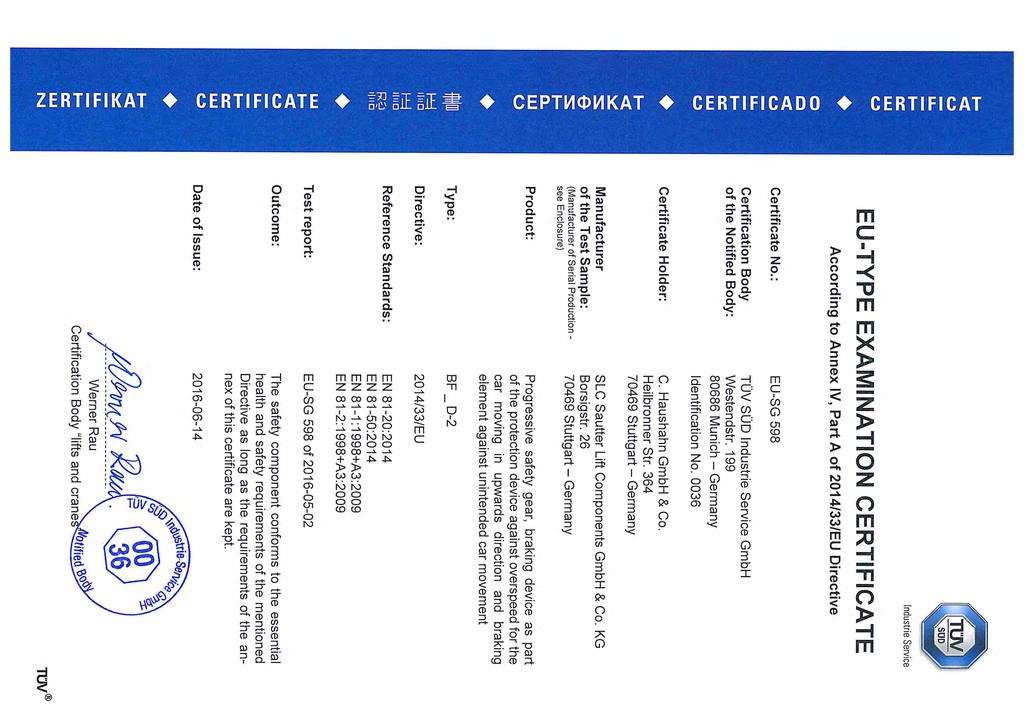
5 General notesfehler! Verweisquelle konnte nicht g 2. General notes 2.1 Designation BF D 2D Progressive safety gear = BremsFangvorrichtung Braking in 1 direction (downwards) Braking in 2 directions (up- and downwards) 3D Braking in 1 direction (upwards) - 1 Type 1 (see manual ) - 2 Type 2 Example BF2D-1 = Progressive safety gear BF braking in 2 directions, Type 1 Type 1 and type 2 are different in construction of the counter brake shoe that affects the maximum load of the safety gear. 2.2 Selection criteria for safety gears Rail head width Load of safety operation P+Q Counterweight mass Car speed Guide rail machined drawn dry oiled dry oiled 2.3 EU type-examination certificates Type Certification no. BF1D-2, BF2D-2, BF3D-2 EC SG 598 Please note: Type-examination certificates according to 95/16 / EC can be downloaded on the homepage of SLC: Manufacturer of the safety gear Manufacturer of the safety gear (under licence of C. Haushahn GmbH & Co. KG) SLC Sautter Lift Components GmbH & Co. KG Borsigstraße 26, Stuttgart, Germany Holder of the type-examination certificate: C. Haushahn GmbH & Co. KG Heilbronnerstraße 364, Stuttgart, Germany Doc I Version Page 5
6 Technical data 3. Technical data 3.1 Range of applications All types Min. width of running surface Rail head width Machined rails Drawn rails dry oiled 1 dry oiled 1 20 mm 9-30 mm Max. rated speed [m/s] Braking force acting upwards F* [N] Braking force acting downwards [N] Max. load braking downwards P+Q [kg] Max. rated speed [m/s] 3.23 Max. load braking downwards P+Q [kg] BF_D-2/BF_D-2 Max. rated speed [m/s] Braking force acting upwards F* Braking force acting downwards [N] [N] Max. load braking downwards P+Q [kg] Max. rated speed [m/s] 3.23 Max. load braking downwards P+Q [kg] BF_D-2/BF_D-2/BF_D Max. rated speed [m/s] Braking force acting upwards F* Braking force acting downwards [N] [N] Max. load braking downwards P+Q [kg] Max. rated speed [m/s] 3.23 Max. load braking downwards P+Q [kg] Use against unintended movement of the car (A3, UCM) Max. rated speed 2 [m/s] Application against unintended movement of the car (not to be mistaken for the maximum permissible rated or tripping speed) 1 The indications for oiled guide rail refer to use of mineral oils without additive (for example lubricant C according to DIN 51517, Part 1). 2 Incl. increase of speed after tripping and after running through of braking element from normal position to acting position. This should be considered when used as a subsystem of the protection device against unintended car movement. This condition is assured with tripping speed max. 2.0 m/s of the part system tripping element of the complete protection device, if the overspeed governor rope is actuated directly at the rotary disc or if the BF standard tripping devices (described in this manual) are used for actuating. Doc I Version Page 6
![Technical data Max. tripping speed of the overspeed governor and range of maximum rated speed: Max. tripping speed [m/s] 2.63 3.23 Max. rated speed [m/s] 2.00-2.29 2.50-2.81 3.](/docs-images/76/72995827/images/7-0.jpg "2 Application as part system of the protection device against unintended car movements 3.2.1 Determination of stopping distance According to EN 81-20:2014-11, chapter 5.6.7.")
7 Technical data Max. tripping speed of the overspeed governor and range of maximum rated speed: Max. tripping speed [m/s] Max. rated speed [m/s] Application as part system of the protection device against unintended car movements Determination of stopping distance According to EN 81-20: , chapter (EN 81-1: A3:2009, chapter 9.11 bzw. EN 81-2: A3:2009, chapter 9.13) the stopping distance is permitted to be max mm, provided that an opening height of minimum 1000 mm between car and door frame remains. This means for a door height of 2000 mm the maximum stopping distance is 1000 mm. Using a system against unintended car movement the lift installer must assure compliance of the maximum stopping distance. To comply with the requirements, the speed of the car at the time of the safety gear actuation may in this case not be greater than 2.2 m/s (see 3.1). Using the safety gear type BF as part system of the protection device against unintended car movement both braking distance and distance of application of the safety gear assembly must be considered. The safety gear assembly consists of safety gear and tripping device. a) Determination of distance of application In case of actuating directly at the rotary disc a distance of application of 24 mm must be considered. Pict. 1: Distance of application for safety gear actuated directly at rotary disc In case of using a tripping device this value is increased. In the next picture a side-mounted tripping device is shown: Pict. 2: Standard tripping device Doc I Version Page 7

8 Technical data Pict. 3: Distance of application for different connections to governor rope Using the standard tripping device side-mounted, five different mountings of the governor rope are possible: mm, mm, mm, mm or mm distance of governor rope to middle of guide rail Because of different lengths of lever the following distances of application result: - 33 mm, - 43 mm, - 53 mm, - 63 mm or - 73 mm. In case of assembly the tripping devices on top or bottom of the outer housing following values result: Pict. 4: Standard tripping device Pict. 5: Distance of application for different connections to governor rope For position 160 mm (distance between governor rope to middle of guide rail) a distance of application of 21 mm results. For position 190 mm accordingly 31 mm, for 220 mm of 41 mm, for 250 mm of 51 mm, for280 mm of 61 mm or for 310 mm of 71 mm. In case of using other tripping devices, the distance of application must be calculated individually according to lengths of lever. Doc I Version Page 8
9 Technical data b) Determination of complete stopping distance caused by safety gear Distance of application and braking distance must be added to determine the complete stopping distance. Using a tripping device side-mounted, assembled at outer housing with a distance of 216 mm to middle of guide rail, following stopping distance in downward direction results: s = distance of application + braking distance This value applies for maximum permissible speed of 2.2 m / s. For slower speeds shorter stopping distances are valid correspondingly. Please note: Above determined stopping distance is only valid for the part system braking. To calculate stopping distance of the complete system reaction times of detection element and of overspeed governor have to be considered and added Requirements and conditions Due to the fact that this part system is just the braking system of the protection device against unintended car movement, the complete system of the protection device against unintended car movement must be complemented by the adequate systems for detection and tripping according to EN81/20: (EN81-1/2: A3:2009). The complete protection device according to EN81/20: (EN81-1/2: A3:2009), consisting of detecting, tripping and braking component, must assure, that the values given in EN81/20: , chapter (EN81-1/21998+A3:2009, chapter and ) are fulfilled. Dimensioning of the complete system to fulfill the required values is in the responsibility of the lift installer. For dimensioning the device as braking system, information of chapter 3.2 in this manual can be used auxiliary. The forces applied to the guide rails in up and down direction must be safely carried by the guide rails (e.g. without sliding the guide rails up or down in their fixings). In addition all operating conditions and limitations of use of the bi-directional acting progressive safety gear BF2D-2 according to EU type examination EU SG 598 apply accordingly. 3.3 Tripping Below the minimum tripping force (whithout tripping device) required to trip the safety gear: Type Braking downwards Braking upwards BF1D N - BF1D-2/BF1D N - BF1D-2/BF1D-2/BF1D N - BF2D N 150 N BF2D-2/BF1D N 175 N BF2D-2/BF2D-2/BF1D N 175 N BF3D N The maximum admissible tripping force required at the safety gear shall not exceed N. The individually needed tripping force has to be ascertained at the lift, considering all components. Standard EN81-20: rules that for the tripping of safety gears twice the required tripping force has to be available - at least 300 N! Doc I Version Page 9
10 Technical data 3.4 State of delivery The safety gear is adjusted by the manufacturer to the following lift specific characteristics: Mass of lift car (P) Mass of payload (Q) Mass of compensation ropes Rated speed of lift car Rail head width (9 30 mm) Manufacturing mode of rails (machined, drawn) Surface condition of rails (dry, oiled) The setting is secured against alterations by the manufacturer by means of a seal. DANGER Incorrect setting of the safety gear can cause a crash of the elevator. The safety gear is adjusted by the manufacturer. As the deceleration depends on different, partially lift-specific factors (material of guide rail, surface hardness of the rail, ) a precise pre-adjustment cannot be guaranteed. If a setting correction is exceptionally required, the setting has to be carried out only by specially trained personnel after consultation with the manufacturer SLC. The new setting has to be secured against unauthorized alterations by means of a seal. WARNING The manufacturer cannot be held liable for damages caused by unauthorized setting alterations. WARNING Before installing the safety gear on the lift car its type plate characteristics have to be compared with the lift characteristics. The type plate is mounted on the safety gear. The safety gear must only be applied within the permission scope of application: see EU type-examination certificate Scope of application, certificate no. see chapter 2.3. IMPORTANT The safety gear is set at work according to values specified in the order form for safety gears to obtain the required braking force. In addition the order form can be downloaded on the homepage of SLC: Doc I Version Page 10
11 Mounting and dimensions 4. Mounting and dimensions Mounting of the safety gear Braking downwards Braking up- and downwards Braking upwards Specification of the safety gear Bore hole for screw M16 (when rail head 9 mm) Setting secured Bore hole for screw M16 Type Pull tube application Installation dimensions with outer casing Weight (Pair) Height Width Depth Installation dimensions without outer casing Weight (Pair) Height Width Depth Standard 45 kg 230 mm 300 mm 152 mm 25 kg 160 mm 230 mm 95 mm Tandem 100 kg 415 mm 420 mm 212 mm 50 kg 330 mm 230 mm 95 mm Triple 150 kg 560 mm 420 mm 212 mm 75 kg 500 mm 230 mm 95 mm Doc I Version Page 11
12 Mounting and dimensions Tripping device Tripping device mounted top/ bottom: The distance between center of the guide rail and first over-speed governor rope: Min.160 mm and max. 250 (310) mm (it is not available for outer housing with customised mounting holes on both sides!) Tripping device side mounted: The distance between center of the guide rail and first overspeed governor rope: Min. 250 mm and max. 376 mm IMPORTANT Find more information about tripping device for safety gear type BF side mounted, mounted top/ bottom and triple on our homepage: Doc I Version Page 12
13 Mounting and dimensions Neutral adjustment (1 piece per pair) (Mounting at same side as overspeed governor) Mounting hole for neutral position in outer housing point of attack for pull tube or tripping device point of attack for pull tube or tripping device centering unit (one piece per pair) safety switch (one piece per pair) pressure spring DA=13, L=75 sheave A 8,4 safety gear shaft leverage Z fastening plate Z screw nut M8 mounting at outer housing screw M8x150 Square type tube 25x25x2 welded at safety gear shaft screw M8x50 square type tube must be bedded rotable Accessories: Safety gear shaft bracket Safety gear shaft bracket, cranked up to buffer diameter (central arrangement) of max. 300 mm Safety gear shaft bracket, straight up to buffer diameter (central arrangement) of max. 150 mm Doc I Version Page 13

 counter brake shoe disk spring assembly Point of attack for braking linkage resp. overspeed governor rope outer housing 11 movable plate 12 type plate 5.")
14 BF Type 2 Specification and function 5. Specification and function 5.1 Specification of the tandem safety gear rotary disc in neutral position brake shoe for downward braking with distance plates brake shoe for upward braking set screw for neutral position guide bolt reset spring (neutral position) counter brake shoe disk spring assembly Point of attack for braking linkage resp. overspeed governor rope outer housing 11 movable plate 12 type plate 5.2 Function of the safety gear Upon tripping of the overspeed governor both rotary discs synchronised by the actuating shaft, are turned by 20. In case of the tandem and triple version the synchronisation of the lower rotary disc is effected by a movable plate 11. Upon braking downwards the lower brake shoe respectively, situated on the rotary disc, moves against the rail surface. The cast housings move relatively to the lift car on guide bolts until the counter shoe touches the rail, pressing the disc spring assemblies together. In the braking process the brake shoes fixed to the rotary discs cut into the rail surface. The braking effect is caused by metal cutting in the rail surface, friction and spring tensioning work. Moving the lift car opposite to the braking direction turns the rotary disc in its neutral position. The safety gear is again in the standby state. IMPORTANT The safety gear transfers the braking forces to the lift car. Be aware of the braking forces in interface design (see chapter 3.1). Doc I Version Page 14


15 Assembly 6. Assembly 6.1 Assembly of the safety gear to the lift car center of rail The safety gear has to be fixed to the lift car with guide bolts or has to be suspended in an outer housing fixed to the lift car. Number of bolts: 2 pieces/side for standard version 4 pieces/side for tandem version 6 pieces/side for triple version The guide bolts have to be secured appropriately. Determine the free bolt length between the casing and the support at the lift car or the outer housing so that the admissible tensioning stress for the bolt material is not exceeded when the safety gear is engaged (e.g. for pins of steel : free bolt length < 40 mm). The bolts have to be protected against corrosion. A spring, sitting on one of the bolts, presses the safety gear against a set screw. This keeps the progressive safety gear in neutral position. WARNING The reset spring has always to be mounted to that side of the rail where the rotary disc is. By means of set screw the horizontal clearance between rail and brake shoe is adjusted. The braking surfaces must be completely covered by the rail running surface. The distance between the rail running surface and the large brake shoe supported by the disk springs is adjusted to 2 mm. The safety gear has to be installed such that the spring supported brake shoe is in parallel with the rail and the travel direction, thus preventing an uneven braking trace. WARNING Make sure that the distance between safety gear (cast iron housing) in neutral position and outer housing is at least 7 mm. Assembly position of the safety gear During assembly take care that the safety gear is correctly positioned. Between the brake shoes and the rotary disc one or more distance plates are inserted. This increases the spring travel and raises the braking force. The brake shoe for braking downwards is underlayed with several distance plates, the brake shoe for braking upwards is normally underplayed with only one plate. The distance plates under the brake shoe on the rotary disc are considerably projecting. The brake shoe on the rotary disc with the most distance plates, has to point downwards in neutral position.. WARNING Check again the position of the distance plate when the safety gear is mounted to the lift car. Incorrect safety gear installation results in functional disorders of the safety gear. Doc I Version Page 15


16 Assembly Connection to overspeed governor (drawings see chapter 4) Both safety gear units on a lift car are linked with an actuating shaft. The actuating shaft is fixed to the safety gear with attachment screws. The actuating shaft is connected by means of two straight connecting tubes or two cranked brackets 25x25x2 mm. Connection via compression-tension rod The rotary disc is connected to the overspeed governor rope with a compression-tension rod. The rod is fixed to the rotary plate by a screw M10 and a retaining washer. The tightening torque fort his screw is 20 Nm. When the overspeed governor is blocked, the tube transfers tension and compression forces from the overspeed governor rope to the rotary plate. When braking downwards the lower brake shoe of the rotary disc is turned against the rail. For the dimensioning of the compression-tension rod the compression force has to be taken into consideration 6.2 Synchronisation of the safety gear Before commissioning the safety gear the synchronisation of the safety devices have to be controlled. Important is the position of the rotary discs: Incorrect position: Correct position: For manual engagement of the rotary disc turn the actuating shaft. If there is a gap between rotary disc and mechanical stop, the position has to be corrected until the gap is removed. For correcting the position the following steps have to be taken: 1. Dismantle the mounting screw M10 between lever and rotary disc. 2. Turn the rotary disc till the mechanical stop of the safety block, hold the disc in this position and tighten the mounting screw M10 again. 3. Test afterward by turning the actuating shaft if the rotary discs of the left and the right safety gear contact the safety block. If this is not the case, repeat the steps mentioned below till the synchronisation is given. Correct position: There is no gap between rotary disc and mechanical stop. Doc I Version Page 16
 make sure that the overspeed governor works properly, if the safety gear is connected to the overspeed governor and if the generated tractive force corresponds with twice the force required for")
17 Commissioning 7. Commissioning 7.1 Functional check WARNING Prior to commissioning the safety gear the synchronisation has to be checked in both directions (see chapter 6.2) make sure that the overspeed governor works properly, if the safety gear is connected to the overspeed governor and if the generated tractive force corresponds with twice the force required for engaging the safety gear. Be aware that the traction force provided by the overspeed governor may depend on the direction. the lift car has to be braked with low speed. It is to be checked whether both brake arms are swinging into their operation position. To check the braking force the safety gear can be tripped at rated speed or overspeed. Upon pullingout of the braking position the brake arm swings automatically into it neutral position. WARNING The safety gear must only be operated in combination a slack rope or an overspeed governor 7.2 Acceptance test IMPORTANT Engagement tests Tests before commissioning the lift according to EN81-20: , chapter 6.3 (EN81-1/2:1998+A3:2009, annex D) resp. periodic tests according to EN81-20: , annex C (EN81-1/2:1998+A3:2009, annex E). 7.3 Check after braking After every braking the safety gear has to be checked by a qualified person. There is to be checked visually whether any changes or dirtying at the braking elements has occurred. The following points are to be rechecked: excessive wear of the brake shoes deformations smooth running The rubbed-off particles have to be removed and the braking marks have to be grinded down. Braking again on a re-grinded braking track is not causing an essential change of the braking force. DANGER For guide rail lubrication only oil products approved in the type examination certificate shall be used. Use machine oil of viscosity class ISO without extreme pressure additive. See mineral oils without additive (for example lubricant C according to DIN 51517, Part 1.) Oils for hydraulic aggregates, gears and motors are not suitable for this use. Doc I Version Page 17
 Safety components from other suppliers 1 Product name CHARACTER 40 Product name of safety gear 2 Release NUMBER 2 3 Revision NUMBER 2 4")
18 QR-code 8. Content of QR-code Description Data field Type Length (symbol) Safety components from other suppliers 1 Product name CHARACTER 40 Product name of safety gear 2 Release NUMBER 2 3 Revision NUMBER 2 4 Identification number CHARACTER 35 SL product number 5 Serial number CHARACTER 18 6 Batch number CHARACTER 10 Only when serial number is not available 7 Manufacturer name CHARACTER 30 Name of manufacturer Manufacturer postal CHARACTER 8 10 Postal code of manufacturer code 9 Manufacturer town CHARACTER 30 Town of manufacturer Manufacturer CHARACTER Two-character country code 10 5 country code according to ISO Importer name CHARACTER 30 Name of importer 12 Importer postal code CHARACTER 10 Postal code of importer 13 Importer town CHARACTER 30 Town of importer Importer country CHARACTER Two-character country code 14 5 code according to ISO Notice: Data fields without values are marked with "---". If numbers 2 and 3 (approval and revision) are not necessary, fields remain empty. Example of QR-code for BF safety gear from SLC: Description Data field Text in QR-code Sample QR-code 1 Product name BF2D-2 2 Release 3 Revision 4 Identification number Serial number Batch number Manufacturer Name SLC Sautter Lift Components GmbH & Co. KG 8 Manufacturer postal code Manufacturer town Stuttgart 10 Manufacturer country code DE 11 Importer name SLS Sassi Lift Systems 12 Importer postal code CM7 2QJ 13 Importer town Braintree 14 Importer country code GB Doc I Version Page 18

19 BF Typ 2 Maintenance 9. Maintenance Upon maintenance the safety gear shall be checked for: smooth operation synchronous operation of the two units wear rust dirt sealing If, after a couple of braking tests, the braking rollers or the safety gear base show signs of wear they are to be replaced by qualified persons. In case of replacing the brake shoes also the mounting screws have to be replaced. Material no.: Packing unit change of brake shoes for rotary disc (type 1 and 2) Transport Any work upon transport, storage, installation and commissioning as well as (if any) demounting and disposal of a safety gear is to be carried out by qualified persons only. They shall be responsible for proper assembly, transport and installation, and for putting the safety gear into operational condition. If this is not ensured, the manufacturer shall not be held liable for any damages that might occur. Upon transport the safety gear must be protected against: humidity shock dirt falling-down, etc. 11. Annex EU type-examination certificate Certificate of conformity IMPORTANT Find more certificates of conformity in additional languages on our homepage: Doc I Version Page 19
20
21
22
23
24
25
26
27 EU-Konformitätserklärung I EU declaration of conformity Der Unterzeichnete Klaus Sautter bestätigt, dass das Bauteil The undersigned Klaus Sautter confirms that the component 1. Beschreibung I Funktion - Bremsfangvorrichtung - Bremseinrichtung als Teil der Schutzeinrichtung für den aufwärtsfahrenden Fahrkorb gegen Übergeschwindigkeit - Bremselement gegen unbeabsichtigte Bewegung des Fahrkorbes Description I Function - Progressive safety gear - Braking device as part of the protection device against overspeed for the car moving in upwards direction - Braking element against unintended car movement 2. Hergestellt von SLC Sautter Lift Components GmbH & Co. KG manufactured by Borsigstraße 26, D Stuttgart 3. Typ I Type BF1D-2, BF2D-2, BF3D-2, 4. Seriennummer und Baujahr siehe Typenschild Serial number and manufacturing year visible on type plate übereinstimmt mit dem geprüften Baumuster (EU-Baumusterprüfbescheinigung), wie in der nachstehenden Übersicht angegeben is in compliance with the type-tested model (EU-Certificate of type examination) as indicated in the below-mentioned list Richtlinie I Directive 2014/33/EU Harmonisierte Normen EN 81-20/50:2014 Harmonised standards EN 81-1/2:1998+A3:2009 Prüfbescheinigung I Type-test certificate EU-SG 598 vom I of Benannte Stelle: Baumusterprüfung Notified body: type examination Benannte Stelle: Produktionsüberwachung Notified body: production monitoring TÜV SÜD Industrie Service GmbH Westendstraße 199, D München (EU-Kennnummer 0036) TÜV SÜD Industrie Service GmbH Westendstraße 199, D München (EU-Kennnummer 0036) Benannte Stelle: Qualitätssicherungssystem TÜV Rheinland Industrie Service GmbH Notified body: quality assurance system Am Grauen Stein, D Köln (EU-Kennnummer 0035) Stuttgart, den SLC Sautter Lift Components GmbH & Co. KG Klaus Sautter Geschäftsführender Gesellschafter I Managing Partner Doc l Version
28 SLC Sautter Lift Components GmbH & Co. KG Borsigstrasse Stuttgart I Germany Phone: +49 (0) Fax: +49 (0)
Product Information Overspeed governor GB 260
 Product Information GB 260 Copyright as per DIN ISO 16016. Manufactured under licence of C. Haushahn GmbH & Co. I Subject to modification. Published by SLC Sautter Lift Components GmbH & Co. KG Borsigstrasse
Progressive safety gear BF66-2
 300.000.023 Version 02.2016 Progressive safety gear Braking downwards Herausgeber Lizenz Copyright SLC Sautter Lift Components GmbH & Co. KG Borsigstraße 26 70469 Stuttgart Telefon: +49 (0) 711.860 62-0
A company of ThyssenKrupp Elevator. ThyssenKrupp Aufzugswerke. Operating Manual. Oil buffer
 A company of ThyssenKrupp Elevator ThyssenKrupp Aufzugswerke Operating Manual Oil buffer OPERATING MANUAL Printer s imprint All rights reserved. Copyright by: THYSSENKRUPP AUFZUGSWERKE GMBH P.O. box 23
Operating and Maintenance Manual. for. HADEF overhead crane. as jointed crane TA
 5.52.714.00.1.0 Edition 03.2004 GB Operating and Maintenance Manual for HADEF overhead crane as jointed crane TA Subject to changes. 1 HADEF Table of Contents 1 General Page 3 2 Product description Page
DRUM ROLL! SAUTTER DRUM DRIVER. Lift without counterweight with drum drive
 DRUM ROLL! SAUTTER DRUM DRIVER Lift without counterweight with drum drive LIFT WITHOUT COUNTERWEIGHT SAUTTER DRUM DRIVER COMPACT, INNOVATIVE, FLEXIBLE FEATURES Traction drive lift without machine room
Instruction manual and installation guide Traction sheave brake TSB TSB
 Instruction manual and installation guide Traction sheave brake TSB 2000-1 TSB 2000-2 Content Traction sheave brake Page 1. Safety 2 1.1 Explanation of symbols 2 1.2. General safety instructions 3 2. Product
Drive Unit e-drive1. Installation instructions 04/2014. English translation of the original German installation instructions
 Drive Unit e-drive1 Installation instructions 04/2014 English translation of the original German installation instructions Contents Foreword... 3 Availability... 3 Structural features in the text... 3
Tension Meter. Edition FT 03.E. FT Series. Instruction Manual. Valid as of: Please keep the manual for future reference!
 Tension Meter FT Series S C H M I D T c o n t r o l i n s t r u m e n t s Edition FT 03.E Model FT Instruction Manual Valid as of: 01.09.2011 Please keep the manual for future reference! Contents 1 Warranty
INSTRUCTION MANUAL. I/P Converter DSG BXXY3Z DSG BXXY4Z
 INSTRUCTION MANUAL I/P Converter DSG BXXY3Z DSG BXXY4Z Revision 2.0 3.626 016136 en Page 1/15 Should you have any questions concerning the I/P converter, please contact the Service Department of the Product
Bi-Directional Progressive Safety Gear
 Bi-Directional Progressive Safety Gear (PRO 2000-A, PRO 2000-B, PRO 5000) Installation and Operation Instructions PRO 2000-A PRO 2000-B PRO5000 PRODUCT PRO2000-A PRO2000-B PRO5000 Speed, P+Q, [m/s] [kg]
DYNATECH PROGRESSIVE SAFETY GEAR PR-2000-UD
 Date: 20-01-2005 Check: 03 DYNATECH PROGRESSIVE SAFETY GEAR PR-2000-UD INSTRUCTIONS FOR USE AND MAINTENANCE - 1 - - 2 - - 3 - - 4 - INSTRUCTIONS FOR USE AND MAINTENANCE 1. GENERAL INDICATIONS. 2. SAFETY
Shovel blade SAB724. Operating instructions and assembly instructions SA36690
 Shovel blade SAB724 Reproduction not permitted, neither in part nor in full. KR-392-002SG 12/2005-1 SA36690 Operating instructions and assembly instructions COPYRIGHT 2002 SABO Maschinenfabrik GmbH Postfach
Installation and Operating Manual for Tank and Equipment Cleaning Nozzles Series 5TM
 Installation and Operating Manual for Tank and Equipment Cleaning Nozzles Series 5TM 150 150 150 This instruction manual contains proprietary information which is protected by copyright laws. No part of
DYNATECH PROGRESSIVE SAFETY GEAR PR-2500-UD (V.50)
") DYNATECH PROGRESSIVE SAFETY GEAR PR-2500-UD (V.50) INSTRUCTIONS FOR USE AND MAINTENANCE - 1 - - 2 - - 3 - - 4 - - 5 - - 6 - INSTRUCTIONS FOR USE AND MAINTENANCE 1. GENERAL INDICATIONS. 2. SAFETY GEAR INSTALLATION.
DYNATECH PROGRESSIVE SAFETY GEAR PR-2500-UD (V.50) INSTRUCTIONS FOR USE AND MAINTENANCE - 1 - - 2 - - 3 - - 4 - - 5 - - 6 - INSTRUCTIONS FOR USE AND MAINTENANCE 1. GENERAL INDICATIONS. 2. SAFETY GEAR INSTALLATION.
Declaration of Conformity as per Directive 97/23/EC
 Declaration of Conformity as per Directive 97/23/EC The manufacturer declares that:, 47906 Kempen, Germany PTFE-lined Rotary plug valves Series 23e, with packing with lever for 90 operation with worm gear
Operating Instructions Garlock Butterfly Valves DN : mm / 2-24
 Operating Instructions Garlock Butterfly Valves DN : 50-600 mm / 2-24 PN : 10 / 16 Type: GAR-SEAL SAFETY-SEAL STERILE-SEAL MOBILE-SEAL Conformity declaration... 14 0 Introduction... 15 1 Proper use...
DYNATECH PROGRESSIVE SAFETY GEAR PQ-3400-UD
 DYNATECH PROGRESSIVE SAFETY GEAR PQ-3400-UD INSTRUCTIONS FOR USE AND MAINTENANCE - 1 - - 2 - - 3 - - 4 - INSTRUCTIONS FOR USE AND MAINTENANCE 1. GENERAL INDICATIONS. 2. SAFETY GEAR INSTALLATION. 2.1. TO
Operating Instructions
 Operating Instructions Ex UPS Combination of > 8265/5 GUBox control panel > 8316 battery box Contents 1 Contents 1 Contents 2 2 General Information 2 3 Safety Instructions 2 4 Conformity to standards 3
Instructions for Use Plain Trolley ULK Geared Trolley UHK
 Instructions for Use Plain Trolley Geared Trolley Item no. Load-carrying capacity (payload) Weight Trolley widths *special trolley widths* Device dimensions mm H / W / D Minimum curve radius mm -005 0,5
Belt Conveyor Pull Rope Switch Types HEN, HEK and SEM OPERATING INSTRUCTIONS
 Belt Conveyor Pull Rope Switch Types HEN, HEK and SEM OPERATING INSTRUCTIONS 2 CE-Sign and Conformity The device meets the requirements of the valid European and national regulations. Conformity has been
EG type-examination certificate
 @ lndustrie Service EG type-examination certificate Certificate no.: Notified body: ApplicanU Gertificate holder: Date of submission: Manufacturer: Product, type: Test Laboratory: Dat and Number of test
Type Operating Instructions. Bedienungsanleitung Manuel d utilisation. 2/2-way solenoid valve 2/2-Wege-Magnetventil Électrovanne 2/2 voies
 Type 5404 2/2-way solenoid valve 2/2-Wege-Magnetventil Électrovanne 2/2 voies Operating Instructions Bedienungsanleitung Manuel d utilisation Contents 1 Operating instructions...2 2 Intended use...3 3
TRACTION MRL LIFT ATLAS EU 2:1. Installation manual /39
 TRACTION MRL LIFT Installation manual 26.08.204 /39 Table of contents. ABOUT THIS DOCUMENT... 4. Document information.... 4.2 Safety warnings definition.... 4.3 Scope of supply.... 4.4 Information concerning
Installation and operating manual Quick closing valve (Bellow sealed) LK product no:
 LK product no:") LK product no: 902002 Article no: 74506 Revision: 2 Contents 1. General information... 3 2. Safety precautions... 3 2.1 Significance of symbols... 3 2.2 Explanatory notes on safety information... 3 3.
LK product no: 902002 Article no: 74506 Revision: 2 Contents 1. General information... 3 2. Safety precautions... 3 2.1 Significance of symbols... 3 2.2 Explanatory notes on safety information... 3 3.
Swing Piston Compressors and Vacuum Pumps
 Swing Piston Compressors and Vacuum Pumps NPK 018 AC Pressure NPK 018 DC Pressure NPK 018 AC Vacuum NPK 018 DC Vacuum Operating and Installation Instructions Read and observe these Operating and Installation
Operating Instructions for Elevator Buffers type LP
 Operating Instructions for Elevator Buffers type LP 1 Scope of application The Elevator Buffer type LP is an energy dissipation type buffer according to EN 81-1/2, EN 81-20, EN 81-50 5.5 and therefore
Operating Instructions Rescue Tools. Accu-tool LKE 50 / LKE 51 LKE 55 / LKE 70 external accu 7 Ah / GB Issue replaces 07.
 Operating Instructions Rescue Tools Accu-tool LKE 50 / LKE 51 LKE 55 / LKE 70 external accu 7 Ah 84150/7060-85 GB Issue 02.2006 replaces 07.2005 1 Contents page 1 Basic operation and designated use of
Electrically Released Brakes ERS VAR11-01 FT = 4100 N
 SM429gb - rev 06/11 S E R V I C E Electrically Released Brakes ERS VAR11-01 FT = 4100 N M A N U A L EC type certificate ABV 775/1 According to drawing 1 12 106946 TUV SUD Industrie Service WARNER ELECTRIC
Series Type ROi400 DE EN FR. Montage- und Betriebsanleitung Installation and operating instructions Instructions de montage et d utilisation
 Montage- und Betriebsanleitung Installation and operating instructions Instructions de montage et d utilisation DE EN FR Member of JOST-World Modellreihe Series Type ROi400 Vollautomatische Anhängekupplung
Rolli D6/5A. Operating Instructions HORN GMBH & CO. KG. Product Description. Safety Indications. Mounting. Commissioning.
 Declaration of Conformity Operating Instructions Rolli D6/5A 440209101-A 03/2004 Subject to technical alterations. Text and design copyrighted. Reprinting and copying, even if excerpts, only with written
Type Operating Instructions. Bedienungsanleitung Manuel d utilisation. 2/2-Way Solenoid Valve 2/2-Wege-Magnetventil Électrovanne à 2/2 voies
 Type 5282 2/2-Way Solenoid Valve 2/2-Wege-Magnetventil Électrovanne à 2/2 voies Operating Instructions Bedienungsanleitung Manuel d utilisation 1 OPERATING INSTRUCTIONS The operating instructions contain
Bowl Feeder BF10 / BF15 Translation of operating and installation instructions
 Bowl Feeder BF10 / BF15 Translation of operating and installation instructions Copyright by Afag GmbH This operation instruction applies to: Bowl feeder right 12 Bowl feeder left 12 Type Order number BF10
Bowl feeder BF20 / BF25 / BF30 BF35 / BF40 / BF50
 Bowl feeder BF20 / BF25 / BF30 BF35 / BF40 / BF50 Translation of original operating instruction Copyright by Afag GmbH This operation instruction applies to: Type Order number BF20 BF25 BF30 BF35 BF40
Operating manual. Custom made gearboxes
 Operating manual Custom made gearboxes DSS-Nr. 100389549 DSS-Rev. 001 Datum 16.01.2018 Contents Contents 1 General information 3 1.1 Using the operating manual 3 1.2 Warnings in this operating manual 4
Installation and operating manual
 LK product no: 901002 and 901102 501002 and 501102 (JIS) Article no: 74500 Revision: 9 Article no: 74500 Revision: 9 2 (23) Contents 1. General information... 5 2. Safety precautions... 5 2.1 Significance
Operating Instructions Ball Valves
 Armaturen GmbH Armaturen, Rohre, Sonderteile aus Edelstahl Fittings, pipes, special parts of stainless steel Operating Instructions KV-SS KV-ZF M & S Armaturen GmbH Carl Benz Str.2 D-75057 Kürnbach Germany
original operating manual Operating manual Translation of the Item-No.: ,
 Translation of the original operating manual Operating manual Item-No.: 015 431 551, 015 431 581 Important! Copyright The operating manual is always to be read before commissioning the equipment. No warranty
HYDRONIC LIFT SOLUTION FOR A3 AMENDMENT
 Page 1/38 Safety Valve HSV Installation, maintenance and startup guide HYDRONIC LIFT SOLUTION FOR A3 AMENDMENT Page 2/38 2011 by Hydronic Lift Spa All right reserved. This documentation, in whole and/or
Assembly and Maintenance Manual Type AS
 Assembly and Maintenance Manual Type AS Hatschekstr.36 69126 Heidelberg Germany Tel +49(0)6221 30470 Fax +49(0)6221 304731 info@stieber.de www.stieber.de Date of issue: 30.05.2018 GB Revision: 0 U:\EngUsers\!ProduktDoku\1AAA_Einbauerklaerung_Wartungsanleitung_Konformitaetserklaerung\1AAA_Wartungsanleitungen\Orginal_Worddatei\_AS.docx
Bowl Feeder BF10 / BF15 Translation of original operating instruction
 Bowl Feeder BF10 / BF15 Translation of original operating instruction Copyright by Afag GmbH This operation instruction applies to: Bowl feeder right 12 Bowl feeder left 12 Type Order number BF10 BF15
Operating Instructions
 Operating Instructions Pendant Light Fitting > Contents 1 Contents 1 Contents...2 2 General Information...2 3 General Safety Instructions...3 4 Conformity to Standards...3 5 Intended Field of Application...3
TSCHAN - TORMAX VSG. Installation and Operation Manual TSCHAN Highly flexible shaft coupling BAWE 009-GBR-0 05/2004
 BAWE 009-GBR-0 05/2004 Installation and Operation Manual TSCHAN Highly flexible shaft coupling TSCHAN - TORMAX VSG TSCHAN GmbH Zweibruecker Strasse 104 D-66538 Neunkirchen-Saar Telephone: +49(0) 6821 866
Bowl feeder BF20 / BF25 / BF30 BF35 / BF40 / BF50
 Bowl feeder BF20 / BF25 / BF30 BF35 / BF40 / BF50 Translation of operating and installation instructions Copyright by Afag GmbH This operation instruction applies to: Type Order number BF20 BF25 BF30 BF35
CONTENTS 1. SIGN ANALYSIS 2. SECURITY EQUIPMENT SELECTION CRITERIA 3. PRODUCT INTRODUCTION 4. GENERAL RULES 5. CONNECTION OF SECURITY EQUIPMENT
 CONTENTS 1. SIGN ANALYSIS 2. SECURITY EQUIPMENT SELECTION CRITERIA 3. PRODUCT INTRODUCTION 4. GENERAL RULES 5. CONNECTION OF SECURITY EQUIPMENT 6. MAINTENANCE DETAILS 7. GENERAL CONDITIONS TO BE PAID ATTENTION
Water level controller and limiter
 Water level controller and limiter RBJ 54 RBJ 64(63) D-07-B-16632-EN-0 Edition 10/09 -i Table of contents- 1. Health and safety instructions 4-5 1.1 General health and safety instructions...4 1.2 Unit-specific
T R A N S L A T I O N Declaration of Conformity as per Directive 2014/68/EU
 T R A N S L A T I O N Declaration of Conformity as per Directive 2014/68/EU The manufacturer declares that: Pfeiffer Chemie-Armaturenbau GmbH, 47906 Kempen, Germany Butterfly valves BR14a, BR14b, BR14b-Type
Type Operating Instructions. Bedienungsanleitung Manuel d utilisation. 2/2-Way Solenoid Valve 2/2-Wege-Magnetventil Électrovanne à 2/2 voies
 Type 5282 2/2-Way Solenoid Valve 2/2-Wege-Magnetventil Électrovanne à 2/2 voies Operating Instructions Bedienungsanleitung Manuel d utilisation Contents 1 Operating Instructions... 2 2 Authorized use...
Installation and Operational Instructions for ROBATIC -clutch Type and Type Sizes 3 9
 Please read the Operational Instructions carefully and follow them accordingly! Ignoring these Instructions may lead to malfunctions or to clutch failure, resulting in damage to other parts. Contents:
Assembly and Maintenance Manual Type ASNU
 Assembly and Maintenance Manual Type ASNU Hatschekstr.36 69126 Heidelberg Germany Tel +49(0)6221 30470 Fax +49(0)6221 304731 info@stieber.de www.stieber.de Date of issue: 30.05.2018 GB Revision: 0 U:\EngUsers\!ProduktDoku\1AAA_Einbauerklaerung_Wartungsanleitung_Konformitaetserklaerung\1AAA_Wartungsanleitungen\Orginal_Worddatei\_ASNU.docx
HST -LS Interlocking device (Translation of Original Manual)
") Installation and Operating Manual for Components HST -LS Interlocking device (Translation of Original Manual) HST-LS Ident.-No.: 10268 HST-LS Ident.-No.: 10269 HST-LS, pictured Ident-Nr. 10269 The image
Installation and Operating Manual for Components HST -LS Interlocking device (Translation of Original Manual) HST-LS Ident.-No.: 10268 HST-LS Ident.-No.: 10269 HST-LS, pictured Ident-Nr. 10269 The image
AXIAL FANS Axis / Tubo OPERATION MANUAL
 TUBO-M AXIS-QA AXIS-Q AXIS-QR AXIS-F AXIS-QRA AXIAL FANS Axis / Tubo OPERATION MANUAL Axis / Tubo www.blaubergventilatoren.de CONTENT 3 Introduction 3 General 3 Safety rules 3 Transport and storage requirements
Type 6213 EV, 6281 EV
 Type 6213 EV, 6281 EV 2/2-way solenoid valve 2/2-Wege-Magnetventil Électrovanne 2/2 voies Operating Instructions Bedienungsanleitung Manuel d utilisation 1 OPERATING INSTRUCTIONS The operating instructions
Storage, operating and maintenance instructions for AZ plug valves and Standard valves
 ARMATUREN Plug - Valves metallic with PTFE Sleeve 2-7 way Storage, operating and maintenance instructions for AZ plug valves and Standard valves Plug - Valves FEP/PFA - lined, 2-3 way Butterfly - Valves
These installation and maintenance instructions must be read in full and completely understood before the installation!
 These installation and maintenance instructions must be read in full and completely understood before the installation! 1. General information on the installation and maintenance instructions These instructions
Installation, Operating & Maintenance Instructions. HV gate valve with pneumatic actuator. Series 110 DN mm (I. D.
 Installation, Operating & Maintenance Instructions HV gate valve with pneumatic actuator Series 110 DN 250 320 mm (I. D. 10" 12") This manual is valid for the following product ordering numbers: 11048-.
PrioVino Premier. Translation of Original Operating Instructions. Status: August First edition January 2018 / PrioVino GmbH
 PrioVino Premier Translation of Original Operating Instructions Status: August 2018 First edition January 2018 / PrioVino GmbH Reprint even in extracts only upon written permission by PrioVino GmbH (ISO
Timing-Belt Reverse Unit 8 80 R25 Notes on Use and Installation
 Timing-Belt Reverse Unit 8 80 R25 Notes on Use and Installation Content General General hazard warning 2 Appropriate use 3 Content Application 3 Technical Data/Scope of Supply 3 Application Options 4 Fitting
EU TOY DIRECTIVE 2009/48/EC: OVERVIEW - REGULATORY CONTEXT AND MAJOR CHANGES
 EU TOY DIRECTIVE 2009/48/EC: OVERVIEW - REGULATORY CONTEXT AND MAJOR The EU Toy Directive was revised in order to take into account the new technological developments and increasing child safety requirements.
Type Operating Instructions. Bedienungsanleitung Manuel d utilisation. 2/2-way solenoid valve 2/2-Wege-Magnetventil Électrovanne 2/2 voies
 Type 6027 2/2-way solenoid valve 2/2-Wege-Magnetventil Électrovanne 2/2 voies Operating Instructions Bedienungsanleitung Manuel d utilisation 1 OPERATING INSTRUCTIONS The operating instructions contain
Bowl feeder WV401-1 / Translation of operating and installation instructions
 Bowl feeder WV401-1 / 402-1 Translation of operating and installation instructions Copyright by Afag GmbH This operation instruction applies to: Bowl feeder WV401-1 Bowl feeder WV402-1 Type 230 V / 50
Z-03+A3 BI-DIRECTIONAL PROGRESSIVE SAFETY GEAR IN COMPLIANCE WITH EN-81-1+A3 STANDARD.
 Z-03+A3 BI-DIRECTIONAL PROGRESSIVE SAFETY GEAR IN COMPLIANCE WITH EN-81-1+A3 STANDARD. 400 INSTALLATION, OPERATION, REPAIR & MAINTENANCE INSTRUCTIONS MANUAL www.zorluasansor.com.tr Z-03+A3 B-PSG CONTENTS
AC 100. Operating instructions Pneumatic Crimper AC 100. Date of issue: 05/2010. Keep for future use!
 Operating instructions Pneumatic Crimper AC 100 Date of issue: 05/2010 Keep for future use! SAFETY SAFETY Basic information The basic prerequisite for ensuring safe use and continuous operation of the
Operating manual Separator
 Operating manual Separator Sheet no. AS/4.1.141.1.1 issue 20.08.2014 Contents Section Title Page 0 Introduction... 1 1 Intended use......1 2 Marking of the fitting... 1 3 Safety instructions... 2 4 Transport
FLENDER ZAPEX couplings. Type ZWT. Operating instructions BA 3505 EN 10/2011. FLENDER couplings
 FLENDER ZAPEX couplings Type ZWT Operating instructions FLENDER couplings FLENDER ZAPEX couplings Type ZWT Operating instructions Translation of the original operating instructions Technical data Notes
Rotary feed-through DDF-S/-KS
 Translation of the Original Operating Manual Rotary feed-through DDF-S/-KS Assembly and Operating Manual Superior Clamping and Gripping Imprint Imprint Copyright: This manual remains the copyrighted property
NEOTECHA NTB-NTC BALL VALVES INSTALLATION AND MAINTENANCE INSTRUCTIONS
 Before installation these instructions must be fully read and understood 2 SAFETY Please also read through these notes carefully. 2.1 General potential danger due to: a. Failure to observe the instructions
OPERATING MANUAL. Black Bruin hydraulic motors S-series model D
 S-series model D CONTENTS 1 GENERAL INSTRUCTIONS... 3 1.1 About the manual... 3 1.2 Revision comments... 3 1.3 Applicability... 3 1.4 Warranty... 3 1.5 Product identification... 3 2 INSTALLATION INSTRUCTIONS...
FLENDER ARPEX Plate packs with close-fitting bolt connection. ARW-4 Sizes to Assembly instructions An 4239 en 12/2015.
 FLENDER ARPEX Plate packs with close-fitting bolt connection ARW-4 Sizes 101-4 to 292-4 Assembly instructions FLENDER couplings FLENDER ARPEX Plate packs with close-fitting bolt connection ARW-4 Sizes
Support T10552 T10595 T40386
 T10552 T10595 T40386 en-gb 7 T10552 T10595... 1 General Information Product name: Product type: Product number: Weight: Max. load capacity: Static test coefficient: 3.0 Intended Use: Load holding device
OPERATING INSTRUCTIONS
 Emergency Cord Switch Type PRS Device identification No.: 91.054 033.001, /.101 and /.201 OPERATING INSTRUCTIONS 2 CE Sign and Conformity The device meets the requirements of the valid European and national
Installation and Operational Instructions for ROBATIC -clutch Types _.0 and _.0 Sizes 3 7
 Please read these Installation and Operational Instructions carefully and follow them accordingly! Ignoring these Instructions may lead to malfunction or to clutch failure, resulting in damage to other
Pressure relief valve
 Pressure relief valve Operating manual Series DHV 712 Version BA-2015.10.20 EN Print-No. 300 510 TR MA DE Rev001 ASV Stübbe GmbH & Co. KG Hollwieser Straße 5 32602 Vlotho Germany Phone: +49 (0) 5733-799-0
Angle seat valve with diaphragm actuator VZXA-...-M
 Angle seat valve with diaphragm actuator VZXA-...-M Instructions Operating (Translation of the original instructions) Festo AG & Co. KG Ruiter Straße 82 73734 Esslingen Germany +49 711 347-0 www.festo.com
A408 GB. Pneumatic oil and diesel pumps 1:1
 03 594 A408 GB Pneumatic oil and diesel pumps 1:1 G Operating instructions for Pneumatic oil and diesel pump 1:1 Contents 1. General details 2 1.1 Intended use 2 1.2 Design and functional description 2
Turbocharger / TPS-H Original assembly instructions English
 Assembly Instructions Turbocharger / TPS-H Original assembly instructions English This document is valid for the TPS-H series: TPS44-H, TPS48-H, TPS52-H Purpose TPS-H turbocharger The assembly instructions
Attachment components SAB01161 Drive system SAB01162 Quick-release coupling SAB00720 Quick-release coupling with drive SAB00922
 Attachment components SAB01161 Drive system SAB01162 Quick-release coupling SAB00720 Quick-release coupling with drive SAB00922 Reproduction not permitted, neither in part nor in full. KR-362-187SG 07/2012-1
User Guide. Lubricus Lubrication System LUB-D1/LUB-D2/LUB-D3/LUB-D4 (24 VDC)
") User Guide Lubricus Lubrication System LUB-D1/LUB-D2/LUB-D3/LUB-D4 (24 VDC) version 04/2013 Content General Information 3 Warning 3 Scope of Supply 3 Overview 3 General safety details 4 Intended use 4
User Guide Lubricus Lubrication System LUB-D1/LUB-D2/LUB-D3/LUB-D4 (24 VDC) version 04/2013 Content General Information 3 Warning 3 Scope of Supply 3 Overview 3 General safety details 4 Intended use 4
Turbocharger / VTR..0, VTR..1 Original assembly instructions English
 Assembly Instructions Turbocharger / VTR..0, VTR..1 Original assembly instructions English This document is valid for the VTR..0/..1 series: VTR160, VTR200, VTR250, VTR320, VTR400 VTR161, VTR201, VTR251,
PN9000 Series Pneumatic Actuators Installation and Maintenance Instructions
 3579049/14 IM-P357-29 CTLS Issue 14 PN9000 Series Pneumatic Actuators Installation and Maintenance Instructions PN9100 PN9200 1. Safety information 2. General product information PN9300 3. Installation
Operating and Installation Instructions Swing Piston Compressors and Vacuum Pumps
 Operating and Installation Instructions Swing Piston Compressors and Vacuum Pumps UNPK04DC Pressure UNPK04DCB Pressure UNPK04DC Vacuum UNPK04DCB Vacuum KNF Neuberger, Inc 2 Black Forest Rd Trenton, NJ
Operating Instructions
 16 1 Independent & Unauthorized Changes and Spare Parts Alterations and changes to actuators are only possible, i.e. permitted under express permission from the company airpower Europe GmbH. These conditions
Attachment components SAB750 Drive system SAB753 Quick-release coupling SAB720 Quick-release coupling with drive SAB722
 Attachment components SAB750 Drive system SAB753 Quick-release coupling SAB720 Quick-release coupling with drive SAB722 Reproduction not permitted, neither in part nor in full. KR-362-035SG 12/2005-1 for
Angle seat valve with piston actuator VZXA-...-K
 Angle seat valve with piston actuator VZXA-...-K Instructions Operating (Translation of the original instructions) Festo AG & Co. KG Ruiter Straße 82 73734 Esslingen Germany +49 711 347-0 www.festo.com
Service - Safety Manual
 Service - Safety Manual Mounting and maintenance instructions Linear Units LT50 series Code Unit Serial number Date by Linear Units LT50 series Table of contents 1 Safety 3 1.1 Significance of the manual
Operating instructions Pull-wire emergency-stop switches EX-ZQ About this document. Content
 Pull-wire emergency-stop switches 1. bout this document Operating instructions.............pages 1 to 6 Original 1.1 Function This operating instructions manual provides all the information you need for
Safety. Operating instructions Solenoid valve VGP DANGER. Contents WARNING CAUTION. Changes to edition Elster GmbH Edition 10.
 27 Elster GmbH Edition.7 Translation from the German 344297 D F NL I E DK S N P GR TR CZ PL RUS H www.docuthek.com Operating instructions Solenoid valve Contents Solenoid valve... Contents... Safety....
Turbocharger / A100-L Original assembly instructions English
 Assembly Instructions Turbocharger / A100-L Original assembly instructions English This document is valid for the A100-L series: A165-L, A170-L, A175-L, A180-L, A185-L, A190-L Purpose The assembly instructions
Instructions for Fitting, Operating and Maintenance
 EN Instructions for Fitting, Operating and Maintenance Retractable Door 1 818 024 RE / 10.2011 ENGLISH Contents 1 Safety Instructions... 3 1.1 Qualified persons... 3 1.2 Symbols and signal words used...
Installation and Operating Instruction for Brake Caliper HW 150 HFA and HW 180 HFA E e
 Installation and Operating Instruction for Brake Caliper HW 150 HFA and HW 180 HFA E 09.736e Schaberweg 30-38 Phone +49 6172 275-0 61348 Bad Homburg Fax +49 6172 275-275 Germany www.ringspann.com info@ringspann.com
Instruction Manual. Sewage lifting station compli 300
 Instruction Manual Sewage lifting station compli 300 Safety instructions Areas of application Electrical connection Installation Servicing Technical data Appendix JUNG PUMPEN GmbH Industriestr. 4-6 33803
OPERATING INSTRUCTIONS. ASTRO HOIST Type E89-CTO
 OPERATING INSTRUCTIONS ASTRO HOIST Type E89-CTO CONFORM TO EN 1808 - MARCH 1999 MACHINE DIRECTIVE 98/37 EC All persons operating this equipment must read and completely understand this manual. Any operation
Swiveling gripper finger GFS 16-40
 Translation of the original manual Swiveling gripper finger GFS 16-40 Assembly and Operating Manual Superior Clamping and Gripping Imprint Imprint Copyright: This manual remains the copyrighted property
Installation manual portable distributors
 EN Installation manual portable distributors EN 60003206 Issue 11.2016 15/11/2016 Table of contents 1 About this manual 3 1.1 Structure of the warnings 3 1.2 Symbols used 4 1.3 Signal words used 4 2 Intended
Translation of the Original operating instructions Lifting device Z 70 /...
 Translation of the Original operating instructions Lifting device Z 70 /... Content 1. Lifting device / Correct use according to regulations 2. Basic principles 3. General information 4. Special remarks
Attachment components SAB00756 Drive system SAB00758 Drive system SAB00760 Quick-release coupling SAB00720 Quick-release coupling with drive SAB00722
 Attachment components SAB00756 Drive system SAB00758 Drive system SAB00760 Quick-release coupling SAB00720 Quick-release coupling with drive SAB00722 Reproduction not permitted, neither in part nor in
Operating Manual TWN 0121/1. Lifting point, screw-type TWN 0122 TWN 0123 TWN 0127 TWN 1120 TWN 1830 TWN 1890
 TWN 0121/1 Operating Manual Lifting point, screw-type TWN 0122 TWN 0123 TWN 0127 TWN 1120 TWN 1830 TWN 1890 THIELE GmbH & Co. KG Werkstraße 3 Tel: +49 (0)2371 / 947-0 58640 Iserlohn www.thiele.de B07905-D
Principle Decision by the Central Experience Exchange Circle of the Notified Bodies and the GS Bodies according to the Product Safety Act ZEK
 -GB-2017-01: Defining the requirements for a GS mark approval Principle Decision by the Central Experience Exchange Circle of the Notified Bodies and the GS Bodies according to the Product Safety Act about
Type Operating Instructions. Bedienungsanleitung Manuel d utilisation
 Type 0131 2/2- or 3/2-way solenoid valve 2/2- oder 3/2-Wege-Magnetventil Électrovanne 2/2 ou 3/2 voies Operating Instructions Bedienungsanleitung Manuel d utilisation 1 OPERATING INSTRUCTIONS The operating
Decree of the Ministry of Transport and Communications
 579/2000 Decree of the Ministry of Transport and Communications on transportable pressure equipment and tanks discharged or filled by pressure and used for the transport of dangerous goods Adopted in Helsinki,
Exchange of rollers from the XTS-Mover
 Service documentation for AT901-0050-0550 and AT9011-00x0-0550 Version: Date: 1.0 0.10.017 Table of contents Table of contents 1 Foreword... 5 1.1 Notes on the documentation... 5 1. Documentation issue