LIMITADOR DE VELOCIDAD DYNATECH/ DYNATECH OVERSPEED GOVERNOR/ LIMITEUR DE VITESSE DYNATECH/ GESCHWINDIGKEITSBEGRENZER DYNATECH/ VEGA
|
|
|
- Sharyl Anissa Oliver
- 6 years ago
- Views:
Transcription
1 LIMITADOR DE VELOCIDAD DYNATECH/ DYNATECH OVERSPEED GOVERNOR/ LIMITEUR DE VITESSE DYNATECH/ GESCHWINDIGKEITSBEGRENZER DYNATECH/ VEGA INSTRUCCIONES DE USO Y MANUTENCIÓN/ INSTRUCTIONS FOR USE AND MAINTENANCE/ INSTRUCTIONS D USAGE ET ENTRETIEN/ GEBRAUCHS- UND WARTUNGSANLEITUNG/
2
3
4
5
6
7
8
9
10
11
12
13 CONTENTS 1 INTRODUCTION MAIN COMPONENTS WORKING PRINCIPLES Overspeed contact Remote tripping mechanism (optional) Remote reset device (Optional) Uncontrolled movement UCM device VEGA LS OVERSPEED GOVERNOR FIXING TO THE FLOOR TECHNICAL FEATURES TYPE OF ADJUSTMENT INSTRUCTIONS OF USE AND MAINTENANCE INSTALLATION DRAWINGS

14 1 INTRODUCTION. The DYNATECH VEGA overspeed governor is designed to cut off the current of the security series line in the event of car overspeed, bringing the lift to a standstill when necessary. The VEGA overspeed governor covers a wide range of speeds and can be used with instant and progressive safety gears. 2 MAIN COMPONENTS. Each governor is composed of the following main elements: a pulley, a centrifugal system, a locking device, a casing and a plate to link the governor to the floor in the machine room. The following picture shows an image of the governor assembly: Where: (1) Main pulley. (2) Centrifugal system. (3) Locking system. (4) Floor fixing plate. 2

15 3 WORKING PRINCIPLES. The governor is of the centrifugal type and is able to work either upwards or downwards. The governor is fixed directly to the floor in the machine room or in the upper part of the well, joined by the rope to its tensing pulley located in the pit. This tensing pulley is attached to the guide pulley by flanges. The rope passes through the groove of the governor and the tensing pulley. The ends of the rope are attached to the linkage anchoring. Thus, when the car reaches its tripping speed, the rope-governor relative movement will lock it. The working diagram is as follows: (4) VEGA governor (5) Governor rope (6) Tension weight As it was indicated above, the governor is secured to the floor in the machine room or to the well. 3
 are attached to")
")
16 The ends of the rope (2) are attached to the linkage anchoring (1) thorugh eyes. 4

.")
 connected to the")
17 The tension weight is secured to the guide rail by flanges. The rope must have enough tension (500 N on each side). In the event of tension loosening a rope slackening contact (1) connected to the installation security series will cut off the current. 5


18 Due to the weight of the masses, the contact is protected from knocks by the part to which it is attached, therefore, the sensor cannot be damaged. The tension weight assembly can be attached to both sides of the guide rail. The guide rail fixing plate has holes on both sides, so that the contact is not a problem when changing the position of the assembly and so that the sensor can be attached on both sides. The loosening margin (*) is shown in the figure below: 6

19 As indicated, if the tightness would be less than acceptable, the bar supporting the weight and the pulley would make contact with the sensor. 3.1 OVERSPEED CONTACT. The governor has a built-in overspeed contact. According to the European Standard UNE-EN 81, at the section, the current cut off by means of the overspeed governor contact is mentioned. In this section is specified that for rated speeds of no more than 1 m/s, the overspeed contact can be triggered when the governor locks. Therefore, the governors, whose rating speed is 1 m/s or lower, will be provided with an overspeed switch that is triggered at the same time as the governor locks. In the left picture the contact situation is shown (1). The contact will act when the governor reaches a speed above the rated speed and a moment before the governor actuates. When this contact is triggered, the current of the security series is cut off. This system has a remote reset. 7

20 For rated speeds above 1 m/s, the overspeed switch must be triggered at a speed above the rated speed, but bellow the tripping speed of the governor. The contact (2) is shown in the right picture. This system has a manually reset. If the governor acts on this contact, the current of the security circuit will not circulate until this contact is manually returned to its initial position Remark: For installations in the well or similar, an automatic reset for this contact is possible. See afterwards 3.2 REMOTE TRIPPING MECHANISM (OPTIONAL) The governor can have a built-in remote tripping mechanism to check the correct interlocking of the governor and the subsequent safety gear wedging. Basically, it consists of a remote interlocking electromagnetic system, which can be driven from the engine room. In order to help during the installation, three versions of the system are available: 8
. A current of 0.2 A must be provided. Remark: Anyway, just a few seconds are necessary to engage the governor.")
21 Solenoid fed by 24 V DC (direct current). A current of 1,1 A must be provided. Solenoid fed by 48 V DC (direct current). A current of 0,75 A must be provided. Solenoid fed by 190 V DC (direct current). A current of 0.2 A must be provided. Remark: Anyway, just a few seconds are necessary to engage the governor. After the activation, the current that feeds the solenoid must be switched off to avoid its overheating. In that way, a button is recommended to activate the system. Some images of it, as well as its position in the set, are shown in the next picture (1). 9

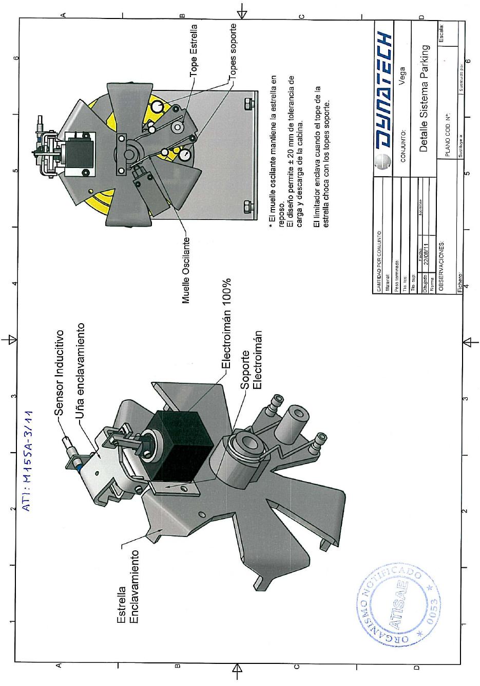
22 3.3 REMOTE RESET DEVICE (OPTIONAL) The governor has the option of a remote reset (R) of the overspeed contact (2). For this device, a solenoid of 24, 8 or 190 V with a current of 1.1, 0.7 and 0.2 A, respectively, is used. 3.4 UNCONTROLLED MOVEMENT UCM DEVICE As a result of application of the new lift standard EN-81-1:1998+ A3, the Vega governor is fitted with a system that can be used to prevent uncontrolled car movement (UCM). This system is called the Parking System. The parking system consists of a unit formed by a pin that makes the centrifugal system lock when it is in its standby position. The system is fitted with an electric magnet that withdraws the pin whenever the car is moving to prevent the pin from locking when the governor is moving- Thanks to this electric magnet and a mechanism that consists of a shaft and a hinge, it is possible to lock or unlock the governor. The system works on positive safety (it is a proactive device). This means that the system will always lock the governor in the event of a cut in the electricity supply. 10


23 The coil installed is an electric magnet that can be 24 V, 48 V or 190 V (all voltages in dc), depending on customer requirements. The operating factor is 100 % in all voltages. When the current to the coil is cut, the pin returns to its standby position thanks to a compression spring fitted in the shaft. The pins therefore remain in the governor locking position. The figure shows a Vega speed governor fitted with the parking system PARKING SYSTEM CONTROL SENSOR: As can be seen in the figure above, the parking system is fitted with a control sensor. This device is an inductive proximity sensor. The job of this sensor is to monitor the system so that if the parking system does not unlock the governor due to a mechanical or electrical fault, the car will not start moving. This avoids any problems that may arise due to the undesired activation of safety parts. 11

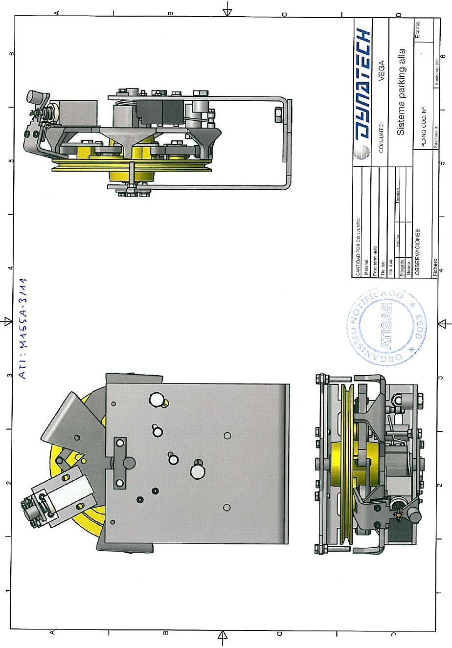
24 3.4.2 THE PARKING SYSTEM FOR UCM. According to Standard EN-81-1:1998+ A3, the car must be stopped within certain margins in light of an uncontrolled movement. The governor in itself is unable to meet requirements. Apart from the governor, safety gear is required and the fitter must therefore perform the appropriate tests to ensure the points of the standard are met. Please see the website and download the manuals for safety gear specifications for the UCM. In the event of uncontrolled car movement, the governor and the parking system will transmit the force to the safety gear in order to stop the car. Dynatech currently offers 2 types of parking system. These systems are described below: ALFA PARKING SYSTEM This system has been sold until now by Dynatech. It is certified under EN-81:A3. The maximum governor locking distances for the different cables are: Cable Ø= Cable Ø= Cable Ø= The response distance of the linkage and the safety gear must be added to this distance. standard. The sum of all the distances must be within the margin established in the 12

25 The distance of the governor may be shorter than that indicated, depending on the position of the locking part in the centrifugal system. Note: The Alfa parking system can be adapted to existing governors with no parking system. Customers can fit the Alfa parking system themselves. BETA PARKING SYSTEM This system replaces the Alfa parking system. It is certified under EN-81:A3. The main advantages in comparison with the Alfa parking system are: - Shorter response distance - Mechanism that avoids auto-engagement. The maximum governor locking distances for the different types of cable are: Cable Ø= Cable Ø= Cable Ø= The response distance of the linkage and the safety gear must be added to this distance. The sum of all the distances must be within the margin established in the standard. The distance of the governor may be shorter than that indicated, depending on the position of the locking part in the centrifugal system. The parking device is fitted with a mechanism that provides a tolerance of ± 20 mm in terms of car loading and unloading. 13
26 Occasionally, the centrifugal system of the governor pulley could stop right next to the parking system locking pin (in standby) at one of the lift stops. This mechanism would avoid any engagement due to a difference in level of the car in both directions. According to Point of the Standard, uncontrolled movement must be detected by a switch. However, detecting uncontrolled movement using the Dynatech design is pointless, as the parking device remains activated when the car is at a standstill. (except in installations with door pre-opening and relevelling). In relation to Section that indicates that once the means have completed their job they must be reset or released by skilled personnel. The fitter can touch the speed governor contact, as this contact is activated whenever the governor starts to run WARNINGS - In the event of a cut in the electricity supply to the electric magnet coil when the car is moving, the speed governor will lock and the safety gear subsequently engaged. The installation of an autonomous power system is recommended to avoid undesired engagement in the event of a cut in the mains electricity supply. - Open the pin to enable the speed governor to turn for manual rescue. If the pin is not released, the governor will lock and the safety gear will engage during the rescue movement. - Open the pin to enable the speed governor to turn for automatic rescue. If the pin is not released, the governor will lock and the safety gear will engage during the rescue movement. 14
27 - Use in installations with re-levelling over 20 mm: in installations with relevelling over 20 mm, certified switching must be used to activate the electric magnet during the re-levelling process because if it re-levels by more than 20 mm then the governor could lock and the safety gear engage. In this case, the switching must discriminate between relevelling and an uncontrolled movement. - Use in installations with door pre-opening: in installations with door preopening, certified switching must be used to ensure the electric magnet remains activated during the pre-opening process because if the electric magnet does not remain activated then the governor could lock and the safety gear engage. In this case, the switching must discriminate between pre-opening and an uncontrolled movement THE PARKING SYSTEM AS REMOTE CONTROL. The parking system can be used as remote control. Operations are the opposite to those of the parking system, as it unlocks the governor when the lift is running under normal conditions. The purpose of the remote control system is to lock the governor when the lift is moving. This takes place during engagement tests. On locking the governor, the safety gear is forced to operate. To do so, a button must be installed on the control panel that disconnects the current to the parking system coil. As indicated above, the parking system unlocks the governor by powering the solenoid valve in this system. If the governor is to be locked while the car is operating normally, this solenoid valve must be disconnected so that the parking system locks the governor. 15
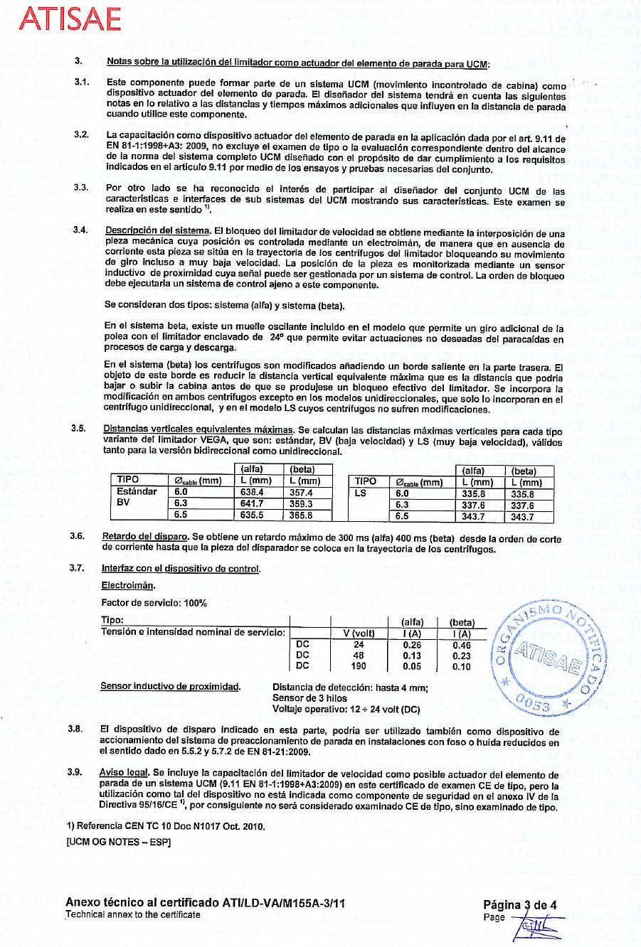
28 3.4.5 TECHNICAL SPECIFICATIONS Electric magnet: Coil with 100% operating factor Voltage (V) I (Alfa p.s.) (A) I (Beta p.s.) (A) 24 DC DC DC Inductive Sensor (for both p.s.): OMRON E2AS08KN04WPB12M M8 inductive proximity sensor Detection distance of up to 4 mm. 3-wire outlet. Operates at V DC Maximum response distance: Alfa Parking System Beta Parking System Cable Ø= Cable Ø= Cable Ø= Mechanism that allows for ± 20 mm movement on loading and unloading in Beta p.s. [Key to diagram: Main proximity sensor circuits Brown Black Load Blue ] 16
29 3.5 VEGA LS OVERSPEED GOVERNOR There is a low speed VEGA governor called VEGA LS. The minimum performance speed is 0.40 m/s This governor is DOWNWARDS ACTING ONLY and the performance speed range is: m/s IMPORTANT NOTE: Customers asking for a VEGA LS, may know that it s unidireccional. In order to know the right way, it must pay attention to to the arrow in the governor. 4 FIXING TO THE FLOOR. The figure shows the governor anchoring points to the lift floor. Distances appear in millimeters. The above figure represents the bottom view of the governor base plate (2). The governor is anchored to the floor using the threaded holes (1) in the 17
30 plate. The rope (3) and its position with respect to the base plate can also be seen in the drawing. 5 TECHNICAL FEATURES. - Machine: Overspeed governor - Model: VEGA - Manufacturing company: DYNATECH, DYNAMICS & TECHNOLOGY, S.L. - Range of use: Maximum rated speed: 2.40 m/s Maximum tripping speed: 3 m/s Minimum rated speed: 0.1 m/s Minimum tripping speed: - From 0.4 to 0.7 m/s, the governor is UNIDIRECTIONAL - From 0.7 to 2.87 m/s the governor is BIDIRECTIONAL - Rope: Diameter: 6 mm, 6.3 mm, 6.5 mm. Composition: 6 x Rope pre-tightness: 500 N This tightness is achieved by positioning the tension weight so that the bar is horizontal. - Tightness produced on the rope during interlocking: Greater than 300 N - Pulley diameter: 200 mm - Overspeed contact. - Other features: It is possible to install several devices: - Remote tripping system - Remote reset - Parking System 18

31 - It can be unidirectional or bidirectional - An encoder can be assembled (VEGA PLUS) - Safety gears with which it may be used: All safety gears with a tripping speed that can be reached by the overspeed governor. 6 TYPE OF ADJUSTMENT. Tripping speed adjusting is carried out by means of a regulating screw which tenses or detenses the centrifugal system spring. When tensing the spring, the speed required to drive the centrifugal system will be higher. In this way, the tripping speed can be adjusted within the speed range. The adjustment is carried out in the factory by means of a computerized gauging system according to the customer specifications. Once the adjustment is finished and checked, it is sealed so that it can not be modified.. 19

32 For tripping speeds lower than 1 m/s, a low speed system is installed, where, as it is shown in the picture, the adjustment is made by means of a tensing screw that lengthen or shrinks the spring that is hooked to the centrifugal system. 20
33 7 INSTRUCTIONS OF USE AND MAINTENANCE. The tripping speed of the installation can be checked by means of the motor frequency changer, by progressively increasing the motor speed until interlocking is obtained. To avoid unnecessary risks that may cause the governor to operate incorrectly, two basic criteria must be taken into account: cleaning and checking for corrosion. There are moving parts in each governor that carry out the interlocking action. The dirt accumulation on these parts may cause malfunctioning. The installer and the maintenance staff must ensure that these parts are perfectly clean. Moreover, all Dynatech governors have rustproof protection, but it is important that the maintenance staff checks the installation to look for any corrosion that may affect any moving part of the elements and that may prevent its natural movement. This check will be carried out by means of a visual inspection of the surfaces conditions and by making the parts move. The frequency of these checks is at the discretion of the maintenance staff, although they should be more frequent in the event of an installation in a particularly corrosive environment. Dynatech will not be held responsible for any problem or accident caused by not observing the indications and advices described both in these instructions and in the EC Type examination certificate. 8 INSTALLATION DRAWINGS. The following drawings may be of help when adapting and installing the VEGA overspeed governor: 21
34 Front view: 22
35 Side view: Bottom view: 23
LIMITADOR DE VELOCIDAD/ OVERSPEED GOVERNOR/ LIMITEUR DE VITESSE/ GESCHWINDIGKEITSBEGRENZER/ VEGA INSTRUCCIONES DE USO Y MANUTENCIÓN/
 LIMITADOR DE VELOCIDAD/ OVERSPEED GOVERNOR/ LIMITEUR DE VITESSE/ GESCHWINDIGKEITSBEGRENZER/ VEGA INSTRUCCIONES DE USO Y MANUTENCIÓN/ INSTRUCTIONS FOR USE AND MAINTENANCE/ INSTRUCTIONS D USAGE ET ENTRETIEN/
DYNATECH DYNAMICS AND TECHNOLOGY, S.L.
 VEGA Plus INSTRUCTIONS Date: 03/10/08 Check 02 DYNATECH DYNAMICS AND TECHNOLOGY, S.L. OVERSPEED GOVERNOR VEGA Plus CONTENTS 1.- INTRODUCTION....1 2.- MAIN COMPONENTS...1 3.- WORKING PRINCIPLES...2 3.1.
SISTEMA DE CONTROL DEL MOVIMIENTO INCONTROLADO DE LA CABINA UNINTENDED CAR MOVEMENT CONTROL SYSTEM
 SISTEMA DE CONTROL DEL MOVIMIENTO INCONTROLADO DE LA CABINA UNINTENDED CAR MOVEMENT CONTROL SYSTEM SYSTÈME DE CONTRÔLE DU MOUVEMENT INCONTRÔLÉ DE LA CABINE KONTROLLSYSTEM FÜR UNBEABSICHTIGTE FAHRKORBBEWEGUNGEN
DYNATECH D-BOX UNINTENDED CAR MOVEMENT CONTROL SYSTEM DYNAMICS AND TECHNOLOGY, S.L.
 DYNATECH DYNAMICS AND TECHNOLOGY, S.L. D-BOX UNINTENDED CAR MOVEMENT CONTROL SYSTEM TABLE OF CONTENTS TABLE OF CONTENTS...- 1-1. INTRODUCTION....- 2-1.1 Description...- 2-2. RISKS AND SECURITY WARNINGS...-
DYNATECH PROGRESSIVE SAFETY GEAR PQ-3400-UD
 DYNATECH PROGRESSIVE SAFETY GEAR PQ-3400-UD INSTRUCTIONS FOR USE AND MAINTENANCE - 1 - - 2 - - 3 - - 4 - INSTRUCTIONS FOR USE AND MAINTENANCE 1. GENERAL INDICATIONS. 2. SAFETY GEAR INSTALLATION. 2.1. TO
DYNATECH PROGRESSIVE SAFETY GEAR PR-2000-UD
 Date: 20-01-2005 Check: 03 DYNATECH PROGRESSIVE SAFETY GEAR PR-2000-UD INSTRUCTIONS FOR USE AND MAINTENANCE - 1 - - 2 - - 3 - - 4 - INSTRUCTIONS FOR USE AND MAINTENANCE 1. GENERAL INDICATIONS. 2. SAFETY
DYNATECH PROGRESSIVE SAFETY GEAR PR-2500-UD (V.50)
") DYNATECH PROGRESSIVE SAFETY GEAR PR-2500-UD (V.50) INSTRUCTIONS FOR USE AND MAINTENANCE - 1 - - 2 - - 3 - - 4 - - 5 - - 6 - INSTRUCTIONS FOR USE AND MAINTENANCE 1. GENERAL INDICATIONS. 2. SAFETY GEAR INSTALLATION.
DYNATECH PROGRESSIVE SAFETY GEAR PR-2500-UD (V.50) INSTRUCTIONS FOR USE AND MAINTENANCE - 1 - - 2 - - 3 - - 4 - - 5 - - 6 - INSTRUCTIONS FOR USE AND MAINTENANCE 1. GENERAL INDICATIONS. 2. SAFETY GEAR INSTALLATION.
Instruction manual and installation guide Traction sheave brake TSB TSB
 Instruction manual and installation guide Traction sheave brake TSB 2000-1 TSB 2000-2 Content Traction sheave brake Page 1. Safety 2 1.1 Explanation of symbols 2 1.2. General safety instructions 3 2. Product
Product Information Overspeed governor GB 260
 Product Information GB 260 Copyright as per DIN ISO 16016. Manufactured under licence of C. Haushahn GmbH & Co. I Subject to modification. Published by SLC Sautter Lift Components GmbH & Co. KG Borsigstrasse
5 Series Active Hybrid 5 F10
 5 Series Active Hybrid 5 F10 (since 12/2011) Legend Airbag Body reinforcement Airbag control unit High-voltage emergency separation point Gas generator Gas-filled shock absorber 12 V battery Active pedestrian
Solenoid interlock AZM 200 The non-contact interlock.
 Solenoid interlock AZM 200 The non-contact interlock. Solenoid interlock AZM 200 The non-contact Solenoid interlocks demand accurate alignment of actuator and device. This requirement is met on new machinery.
JEEVES. JEEVES Installation Manual. Installation Manual The Easiest Do-It-Yourself Dumbwaiter on the Market
 1 888-323-8755 www.nwlifts.com JEEVES Installation Manual The Easiest Do-It-Yourself Dumbwaiter on the Market This manual will cover the installation procedure step-by-step. The installation of this dumbwaiter
AU DU PONT DE LUTTRE BRUSSELS BELGIUM PHONE: FAX: OPERATING MANUAL. Electric Fully Automatic Floor Saw FS 1218 EX
 AU DU PONT DE LUTTRE 74-1190 BRUSSELS BELGIUM PHONE: 322 34 83 162 FAX: 322 34 83 136 OPERATING MANUAL Electric Fully Automatic Floor Saw FS 1218 EX 2 Important information before you start! When the machine
Operating, Safety. Maintenance Manual. for. Roller Shutter & Sectional. Overhead Doors
 Operating, Safety & Maintenance Manual for Roller Shutter & Sectional Overhead Doors Indupart Ltd The Door Centre Discovery Park Crossley Rd Ind Est Stockport, Cheshire SK4 5BW T: 0161 432 6655 F: 0161
HV Gate Valve with pneumatic actuator
 HV Gate Valve with pneumatic actuator This manual is valid for the valve ordering number(s): 09134-_E14/24/34/44 09136-_E14/24/34/44 09138-_E14/24/34/44 09140-_E14/24/34/44 09144-_E14/24/34/44 The fabrication
DESCRIPTION OF OPERATION EcoSpace elevator with KCM831 control
 Owner s UM-01.26.001-USK All DRAFT KONE Montana 2011 rights Corporation KONE (-) guide reserved Elevator 2011-02-24 Corporation Project DESCRIPTION OF OPERATION EcoSpace elevator with KCM831 control All
POLEA TENSORA QUASAR QUASAR TENSING PULLEY POULIE DE TENSION QUASAR QUASAR-SPANNROLLE
 POLEA TENSORA QUASAR QUASAR TENSING PULLEY POULIE DE TENSION QUASAR QUASAR-SPANNROLLE INSTRUCCIONES DE USO Y MANUTENCIÓN/ INSTRUCTIONS FOR USE AND MAINTENANCE/ INSTRUCTIONS D USAGE ET ENTRETIEN/ GEBRAUCHS-
panasonic.net/id/pidsx/global Solve issues related to machine safety and other safety measures with a safety door switch with key!
 655 Door with Key SERIES Related Information General terms and conditions... F-7 General precautions... P.50 PHOTO PHOTO Conforming to Machine & EMC Directives Recognition Certified MEASURE ITY panasonic.net/id/pidsx/global
HST -LS Interlocking device (Translation of Original Manual)
") Installation and Operating Manual for Components HST -LS Interlocking device (Translation of Original Manual) HST-LS Ident.-No.: 10268 HST-LS Ident.-No.: 10269 HST-LS, pictured Ident-Nr. 10269 The image
Installation and Operating Manual for Components HST -LS Interlocking device (Translation of Original Manual) HST-LS Ident.-No.: 10268 HST-LS Ident.-No.: 10269 HST-LS, pictured Ident-Nr. 10269 The image
JBI Docupunch P33 Automatic Punch
 JBI Docupunch P33 Automatic Punch Instruction Manual Provided By http://www.mybinding.com http://www.mybindingblog.com TABLE OF CONTENTS SECTION I: INSTALLATION & TESTING: 1) Uncrating, Inspection & removal
UNI EN ISO EN
 Airplus Safeline eneral Upon implementation of the AIRPLUS T series, air-treatment units, PNEUMAX develops a supply and discharge valve, with an electropneumatic control and spring-return, fitted with
Application Note. First trip test. A circuit breaker spends most of its lifetime conducting current without any
 Application Note First trip test A circuit breaker spends most of its lifetime conducting current without any operation. Once the protective relay detects a problem, the breaker that was idle for maybe
Type Operating Instructions. Bedienungsanleitung Manuel d utilisation. 2/2-Way Solenoid Valve 2/2-Wege-Magnetventil Électrovanne à 2/2 voies
 Type 5282 2/2-Way Solenoid Valve 2/2-Wege-Magnetventil Électrovanne à 2/2 voies Operating Instructions Bedienungsanleitung Manuel d utilisation 1 OPERATING INSTRUCTIONS The operating instructions contain
Inteli-Lift GEN II DUMBWAITER
 1 877-345-4387 530-295-4900 www.eilifts.com Inteli-Lift GEN II DUMBWAITER The Easiest Dumbwaiter system on the Market Fully UL Certified Dumbwaiter Systems UL File # SA32120 This manual will cover the
Type Operating Instructions. Bedienungsanleitung Manuel d utilisation. 2/2-way solenoid valve 2/2-Wege-Magnetventil Électrovanne 2/2 voies
 Type 6027 2/2-way solenoid valve 2/2-Wege-Magnetventil Électrovanne 2/2 voies Operating Instructions Bedienungsanleitung Manuel d utilisation 1 OPERATING INSTRUCTIONS The operating instructions contain
Operating manual Separator
 Operating manual Separator Sheet no. AS/4.1.141.1.1 issue 20.08.2014 Contents Section Title Page 0 Introduction... 1 1 Intended use......1 2 Marking of the fitting... 1 3 Safety instructions... 2 4 Transport
Type 6213 EV, 6281 EV
 Type 6213 EV, 6281 EV 2/2-way solenoid valve 2/2-Wege-Magnetventil Électrovanne 2/2 voies Operating Instructions Bedienungsanleitung Manuel d utilisation 1 OPERATING INSTRUCTIONS The operating instructions
BRAKES. Section III REAR AXLE DATA AND SPECIFICATIONS HAND BRAKE CHRYSLER SERVICE MANUAL BRAKES 17
 BRAKES 17 There is no basic design change in the rear axle and sure grip differential except the larger diameter pinion shaft is now used on all models for 1959. The Service Procedures will remain the
8 BK brakes. 8.1 Description of BK brakes (CMP40 to CMP63) Description of BK brakes (CMP40 to CMP63)
 Description of BK brakes (CMP40 to CMP63)") 8 BK brakes Description of BK brakes (CMP0 to CMP6) 8 BK brakes 8. Description of BK brakes (CMP0 to CMP6) The mechanical brake is a holding brake implemented as a permanent magnet brake. The standard
8 BK brakes Description of BK brakes (CMP0 to CMP6) 8 BK brakes 8. Description of BK brakes (CMP0 to CMP6) The mechanical brake is a holding brake implemented as a permanent magnet brake. The standard
RACK JACK. Synchronous Lifting Systems
 RACK JACK Synchronous Lifting Systems RACK JACK (ROUND RACK TYPE) Operation The Rack Jack from WMH Herion provides simple synchronous lifting motion. The system of rack and pinion transforms linear motion
HEAVY DUTY PNEUMATIC TORQUE WRENCH (C-RAD) USER GUIDE
 USER GUIDE") HEAVY DUTY PNEUMATIC TORQUE WRENCH (C-RAD) USER GUIDE Ref: WCOI.041 Date: June 2015 Issue: 4 Page Description CONTENTS 1 Introduction Training Requirements 2 General Safety 3 C-RAD Wrench Models Covered
HEAVY DUTY PNEUMATIC TORQUE WRENCH (C-RAD) USER GUIDE Ref: WCOI.041 Date: June 2015 Issue: 4 Page Description CONTENTS 1 Introduction Training Requirements 2 General Safety 3 C-RAD Wrench Models Covered
L.IVE.LS.C.M (RWD Single Tire) Iveco Daily L and S (2005)
 Iveco Daily L and S (2005)") Auxiliary Air Suspension Installation Manual (RWD Single Tire) Iveco Daily L and S (2005) November 2018 CONTENTS 1. FOREWORD... 3 2. INTRODUCTION... 4 3. VERY IMPORTANT NOTES... 5 4. INSTRUCTIONS FOR INSTALLATION...
Auxiliary Air Suspension Installation Manual (RWD Single Tire) Iveco Daily L and S (2005) November 2018 CONTENTS 1. FOREWORD... 3 2. INTRODUCTION... 4 3. VERY IMPORTANT NOTES... 5 4. INSTRUCTIONS FOR INSTALLATION...
F3S-TGR-KHL1/-KHL3/-KHL3R
 Safety guard-lock door switches with full stainless steel body F3S-TGR-KHL1/-KHL3/-KHL3R The F3S-TGR-KHL3 safety-door switch keeps medium to large guard doors closed until hazards have been removed. It
FUNCTIONAL SAFETY SOLUTIONS in Solenoid Valves
 FUNCTIONAL SAFETY SOLUTIONS in Solenoid Valves Safety is reality and is part of our daily business. The same applies to ASCO; it is reality and part of your safety. You can rely on our focus on reliable
Operating and maintenance handbook Brake motors series CCL
 Operating and maintenance handbook Brake motors series CCL Rev. 01 SAFETY BRAKE SERIES CCL Specifications of the brake series CCL The electromechanic spring brake series CCL is a direct current brake.
NEUFORM 3-Blade-Variable Pitch Propeller R2 Series. Assembly and Maintenance Manual
 NEUFORM 3-Blade-Variable Pitch Propeller R2 Series for Rotax 912, 912S and 914 Manual control by hand lever (H) or electric constant speed control (ECS) Date: 28 April 2010 Your NEUFORM-Distributor: Table
Bi-Directional Progressive Safety Gear
 Bi-Directional Progressive Safety Gear (PRO 2000-A, PRO 2000-B, PRO 5000) Installation and Operation Instructions PRO 2000-A PRO 2000-B PRO5000 PRODUCT PRO2000-A PRO2000-B PRO5000 Speed, P+Q, [m/s] [kg]
WAP disc brake technology. Assembly, operating and maintenance instructions
 WAP disc brake technology Assembly, operating and maintenance instructions Number MA-025 Date 22.07.2010 1 Please read this operating and service manual before starting the vehicle. It forms part of the
DG 060 DG 061 DG 062 DG 063 DG 064 for Pressure and High Pressure Filters Operating pressure up to 600 bar Response/switching pressure up to 5,0 bar
 Clogging Indicators DG 060 DG 061 DG 062 DG 063 DG 064 for Pressure and High Pressure Filters Operating pressure up to 600 bar Response/switching pressure up to 5,0 bar Description Application Monitoring
Catalog Mars Low voltage Brake motors
 Catalog Mars 2014 Low voltage Brake motors We provide motors, generators and mechanical power transmission products, services and expertise to save energy and improve customers processes over the total
SI AT A22. English. Printed: Doc-Nr: PUB / / 000 / 01
 SI AT A22 English 1 Information about the documentation 1.1 About this documentation Read this documentation before initial operation or use. This is a prerequisite for safe, trouble-free handling and
Accessories smart additions for efficiency and intelligent performance
 smart additions for efficiency and intelligent performance Metal bellows couplings Perfectionists you can count on Metal bellows couplings are designed for the highest requirements in servo drive technology.
Fig.1 Sky-hook damper
 1. Introduction To improve the ride comfort of the Maglev train, control techniques are important. Three control techniques were introduced into the Yamanashi Maglev Test Line vehicle. One method uses
Maintenance Manual. Hephestos
 Hephestos 2016 Mundo Reader SL. All rights reserved. The reproduction, copying, distribution, publication or modification of this material is strictly prohibited unless carried out with the express prior
The Discussion of this exercise covers the following points:
 Exercise 2 Float Switch EXERCISE OBJECTIVE Learn the working principle of float switches and how to use the float switch, Model 46935. DISCUSSION OUTLINE The Discussion of this exercise covers the following
Ch 20 Inductance and Faraday s Law 1, 3, 4, 5, 7, 9, 10, 11, 17, 21, 25, 30, 31, 39, 41, 49
 Ch 20 Inductance and Faraday s Law 1, 3, 4, 5, 7, 9, 10, 11, 17, 21, 25, 30, 31, 39, 41, 49 The coil with the switch is connected to a battery. (Primary coil) When current goes through a coil, it produces
SI AT A22. English. Printed: Doc-Nr: PUB / / 000 / 03
 SI AT A22 English 1 Information about the documentation 1.1 About this documentation Read this documentation before initial operation or use. This is a prerequisite for safe, trouble-free handling and
Progressive Central Lubrication Systems
 Table of contents 4 Technical basics System description... 04-0-0-0 Construction, applications, advantages, function System design... 04-0-0-02 Design and installation of progressive systems Calculation
HYDRONIC LIFT SOLUTION FOR A3 AMENDMENT
 Page 1/38 Safety Valve HSV Installation, maintenance and startup guide HYDRONIC LIFT SOLUTION FOR A3 AMENDMENT Page 2/38 2011 by Hydronic Lift Spa All right reserved. This documentation, in whole and/or
Type Operating Instructions. Bedienungsanleitung Manuel d utilisation. 2/2-Way Solenoid Valve 2/2-Wege-Magnetventil Électrovanne à 2/2 voies
 Type 5282 2/2-Way Solenoid Valve 2/2-Wege-Magnetventil Électrovanne à 2/2 voies Operating Instructions Bedienungsanleitung Manuel d utilisation Contents 1 Operating Instructions... 2 2 Authorized use...
SG-B1 SERIES / SG-A1 SERIES
 643 Door with Solenoid Interlock / Door Ultra-slim SG-B1 SERIES / SG-A1 SERIES Related Information General terms and conditions... F-7 General precautions... P.1501 PHOTO PHOTO Conforming to Machine &
INSTRUCTIONS FOR MODELS # 2200/#2400
 --- WARNING --- 1. A hot stamping press applies high pressure with heat to the article being marked. Care should be taken by the operator to keep hands free of the stamping area whenever the equipment
6204 Series Low-Volume Inserter
 204 Series Low-Volume Inserter /2012 MAINTENANCE MANUAL Mechanical description Mechanical description...51 General...52 Covers and plates...52 Electrical components...57 Feeder modules...0 Document feed...4
PTEX extruder pumps Pneumatic extruder pump for drums of grease up to NLGI grade 2
 1-4009-EN PTEX extruder pumps Pneumatic extruder pump for drums of grease up to NLGI grade 2 The PTEX extruder pumps are pneumatically actuated pumps designed to deliver lubricant under pressure to lubrication
An Investment in Plant Floor Safety. 802C Safety Cable Pull Switches 802E Hinge Safety Interlock Switches 802F Safety Interlock Switches
 An Investment in Plant Floor Safety 802C Safety Cable Pull Switches 802E Hinge Safety Interlock Switches 802F Safety Interlock Switches Notes 2 802C Cable Pull Safety Switches Safety and Application Safety
CETOP POSITION PAPER PP 07
 CETOP POSITION PAPER PP 07 MACHINERY DIRECTIVE 2006/42/EC Valid since 26 th May 2010 CETOP General Secretariat Lyoner Straße 18 D-60528 Frankfurt am Main Phone: +49 69 6603 1201 Fax: +49 69 6603 2201 E-mail:
Clogging Indicators. Description. Page 393. Application Monitoring the contamination of pressure and high pressure filters.
 Clogging Indicators DG 023 DG 024 DG 041 DG 042 for Pressure and High Pressure Filters Operating pressure up to 450 bar / 5627 psi Response / switching pressure up to 5.0 bar / 73 psi Description pplication
CAM CLUTCHES BREU SERIES
 CAM CLUTCHES BREU SERIES TSUBAKI EMERSON - the working principle of lift-off Cam Clutches - 2 Cams of BREU series Cam Clutches are designed to lift off, having no more contact with inner- and outer race
Motional EMF. F = qvb
 Motional EMF When a conducting rod moves through a constant magnetic field, a voltage is induced in the rod. This special case of electromagnetic induction arises as a result of the magnetic force that
Valves. Rapid opening and closing solenoid valves VMR (E1110 rev /11/2012)
") Valves Rapid opening and closing solenoid valves VMR (E1110 rev. 03-19/11/2012) GENERAL WARNINGS: DISPOSAL: ¾ All installation, maintenance, ignition and setting must be performed by qualified staff, respecting
Valves Rapid opening and closing solenoid valves VMR (E1110 rev. 03-19/11/2012) GENERAL WARNINGS: DISPOSAL: ¾ All installation, maintenance, ignition and setting must be performed by qualified staff, respecting
TECHNICAL MANUAL GTB16N
 TECHNICAL MANUAL GTB16N 1/20 1. INTRODUCTION 1.1 Purpose 1.2 Before Service 1.3 Safety 1.3.1 Hazard Definitions 1.3.2 For Your Safety 1.4 Specifications & dimensions 1.5 Description 2. HYDRAULIC SYSTEM
Function description of roll-over bar
 91-800 Function description of roll-over bar Roll-over bar system, model 129 (version up to approx. 05/95) P91.50-0203-59 A1e29 Roll-over bar warning lamp (RB) S68/7 Front left seat belt buckle/seat belt
OPERATIONAL INSTRUCTION OVERVIEW MAINTENANCE CHECKLIST
 OPERATIONAL INSTRUCTION OVERVIEW Operation Both manual and electrically powered winches develop tremendous forces; therefore, all backstops must be operated by qualified personnel only to avoid structural
Edition Manual Chapter Page Workshop Manual, Stiga Park 5 Belts 11
 2008-05-19 Workshop Manual, Stiga Park 5 Belts 11 Pro 20 1. Dismantle the belts A and B as described above. 2. Block up the rear frame and remove the right rear wheel. Clean carefully the insex hole in
Innovative Controlby Wire Technology for Elevator Safety
 Innovative Controlby Wire Technology for Elevator Safety Dr.-Ing. Etienne Nitidem Interlift 2015 VFA-Forum Agenda State-of-the-art technology of safeties components in Elevators Possible improvements of
S02. MAGNETIC PARTICLE TESTING
 S02.1 Scope This procedure is for the examination of ferromagnetic surface and near surface indications in stressed areas of welds, drilling or production equipment, or as a prove up technique. Both wet
TECHNICAL INFORMATION
 Radial Roller Bearings Fitting and Mounting Fixed Bearings and Float Bearings Radial and axial loads in bearing units can be transmitted by fixed and floating bearings A fixed bearing is generally used
Start-up and Operation
 Start-up and Operation NEVER FORGET THAT ANY MACHINE CAN BE VERY DANGEROUS WHEN NOT OPERATED CORRECTLY AND SAFELY. ALWAYS VISUALLY CHECK TO MAKE SURE THAT ALL PERSONS ARE CLEAR BEFORE TURNING ON ANY CONTROLS.
G4 Diesel Fuel Shut off Valve A very safe method to protect YOUR engine
 G4 Diesel Fuel Shut off Valve A very safe method to protect YOUR engine With the G4 2-position /4 way fuel valve When an alarm signal occurs, the G4 fuel valve instantly reverses the supply pump suction
Operating Instructions: Hand-operated, PTFE-lined butterfly valves, Series 22/23
 0 Introduction These instructions are intended to assist users of BRAY PTFE-lined butterfly valves, Series 22/23 in fitting, operating and servicing valves. Risks may arise and the manufacturer's warranty
837. Dynamics of hybrid PM/EM electromagnetic valve in SI engines
 837. Dynamics of hybrid PM/EM electromagnetic valve in SI engines Yaojung Shiao 1, Ly Vinh Dat 2 Department of Vehicle Engineering, National Taipei University of Technology, Taipei, Taiwan, R. O. C. E-mail:
Spring hangers, spring supports
 Spring hangers, spring supports 2 spring Spring hangers, supports PRODUCT 2 GROUP Spring hangers, spring supports Contents Page Field of application...2.1 Overview of spring hangers and spring supports...2.3
Operating Instructions BNT-40 Automatic Rebar Tying Machine
 Operating Instructions BNT-40 Automatic Rebar Tying Machine This Tool Has Passed ISO9001 International Quality System Certification The charger has passed ETL Certification BNT-40 Technical Manual.indd
DG 023 DG 024 DG 025 DG 041 DG 042. Clogging Indicators
 Clogging Indicators DG 03 DG 04 DG 05 DG 041 DG 04 For Pressure and High Pressure Filters Operating pressure up to 657 psi Response/Switching pressure up to 73 psi 60.30-4us Description Application Monitoring
accidents which arise due to nonobservance and the safety information herein.
 2000LB WINCH Model: 7247 CALIFORNIA PROPOSITION 65 WARNING: You can create dust when you cut, sand, drill or grind materials such as wood, paint, metal, concrete, cement, or other masonry. This dust often
CRANE OPERATION INSTRUCTION AND GUIDELINES
 CRANE OPERATION INSTRUCTION AND GUIDELINES Qualifications Crane operation, to be safe and efficient, requires skill, the exercise of extreme care and good judgment, alertness and concentration, and a rigid
MAINTENANCE INSTRUCTIONS
 MAINTENANCE INSTRUCTIONS ECOMAT EASY / GIROTEC WRS Version G0101 ECOMAT EASY H / GIROTEC WRS H Version G0301 ECOMAT PLUS / ECOMAT PLUS H Versions G0503 / G0603 V 2.0 Table of contents 1/3 1.0 Maintenance
LED Stealth 3 Visor Light Instruction and Operations Manual
 LED Stealth 3 Visor Light Instruction and Operations Manual You have just purchased the LED Stealth 3 visor light bar from Extreme Tactical Dynamics. Your new interior visor light bar is made with only
Heavy-Duty Shock Absorbers LDS 25. Deceleration Technology. ONLINE Calculation and 2D / 3D CAD Download. F m.
 Heavy-Duty Shock bsorbers Deceleration Technology ONLINE Calculation and 2D / 3D CD Download F m V S Operating Principle Steel Cap Piston rod Filling Valve for Nitrogen Operating Principle LDS models are
PNEUMATIC TORQUE WRENCH (C-RAD) USER GUIDE
 USER GUIDE") PNEUMATIC TORQUE WRENCH (C-RAD) USER GUIDE Ref: WCOI.031 Date: Mar 2017 Issue: 10 Page Description CONTENTS 1 Introduction Training Requirements 2 General Safety 3 C-RAD Wrench Models Covered By Manual
PNEUMATIC TORQUE WRENCH (C-RAD) USER GUIDE Ref: WCOI.031 Date: Mar 2017 Issue: 10 Page Description CONTENTS 1 Introduction Training Requirements 2 General Safety 3 C-RAD Wrench Models Covered By Manual
RPM Inductive XENON TIMING LIGHT
 RPM Inductive XENON TIMING LIGHT PART NO G4132 HANDBOOK RPM Inductive INDEX Page 1. XENON TIMING LIGHT 2 2. PRINCIPLE OF OPERATION 2 3. IMPORTANCE OF IGNITION TIMING 3 4. USE OF UNLEADED PETROL 3 5. TIMESTROBE
Rescue Hoist Ground Support Equipment
 Rescue Hoist Ground Support Equipment Zephyr International LLC 120 Royal Manor Rd. Easton, PA 18042 USA zephyrintl@rcn.com Page 1 of 6 Introduction: Helicopter rescue hoists use tension rollers to keep
Operating instructions Solenoid interlock TKM/TKF. 1. About this document. Content
 1. About this document Operating instructions.............pages 1 to 6 Original 1.1 Function This operating instructions manual provides all the information you need for the mounting, set-up and commissioning
Introduction. Lift and Escalator Safety and their Protection. Lifts and Escalators Mechanism in HK Lift System Escalator System
 Lift and Escalator Safety and their Protection IMechE CPD Certificate Course Date: 21 Nov. 2016 1 Introduction Lifts and Escalators Mechanism in HK Lift System Escalator System 2 The (Lifts & Escalators)mechanism
Installation manual. Intake system and ventilation. Industrial engines DC09, DC13, DC16 OC16. 01:02 Issue 10 en-gb. Scania CV AB 2018, Sweden
 Installation manual Intake system and ventilation Industrial engines DC09, DC13, DC16 OC16 01:02 Issue 10 en-gb Changes from the previous issue...3 Intake air...4 Intake air taken from outside engine room...
OFFICINE OROBICHE S.p.A. 1/7 INSTRUCTION MANUAL FOR FLOW SWITCHES PL SERIES
 OFFICINE OROBICHE S.p.A. 1/7 INSTRUCTION MANUAL FOR FLOW SWITCHES PL SERIES 1.INSTRUMENT DESCRIPTION Flow switches PL series are designed to be mounted in an upright position along horizontal pipes. These
Northern Sales & Distribution Centre
 User Manual Industrial Door Northern Sales & Distribution Centre The Door Centre, Discovery Park, Crossley Road, Stockport, SK4 5BW /indupart /indupart /indupart /company/indupart-ltd Foreword This user
SERVICE MANUAL. Permobil C350. Power Wheelchair
 SERVICE MANUAL US Permobil C350 Power Wheelchair Contents Contents Introduction... 5 Rating plates... 6 Covers... 8 Batteries... 10 Rear wheels... 12 Support wheels... 14 Front wheels... 16 Wheel fork...
Electronic Testing Category 5
 Electronic Testing Category 5 Kevin Heling, March 13, 2018 WE START HERE: Rope load measuring sensors (Henning Mobile Weight Watcher System): foundation of the Alternative Testing Method (electronic testing)
FOUR POST LIFT STRONGMAN TOOLS. Manual to be used with only Strongman Tools Ltd 4 Post Lift
 FOUR POST LIFT STRONGMAN TOOLS Manual to be used with only Strongman Tools Ltd 4 Post Lift 2. SAFETY WARNINGS Thoroughly read this manual before operating the lift and comply with the instructions. Always
INSTRUCTION MANUAL. I/P Converter DSG BXXY3Z DSG BXXY4Z
 INSTRUCTION MANUAL I/P Converter DSG BXXY3Z DSG BXXY4Z Revision 2.0 3.626 016136 en Page 1/15 Should you have any questions concerning the I/P converter, please contact the Service Department of the Product
Worksheet 1 - Simple digital sensors 3. Worksheet 2 - Lamps and simple actuators 6. Worksheet 3 - Using transistors 8. Worksheet 4 - Relays 10
 Contents Worksheet 1 - Simple digital sensors 3 Worksheet 2 - Lamps and simple actuators 6 Worksheet 3 - Using transistors 8 Worksheet 4 - Relays 10 Worksheet 5 - Analogue inputs 12 Worksheet 6 - Fault
Maintenance and Repair Instructions TM 89/03
 TM 89/0 410 X 180 Simplex 410 X 180 Duplex 500 X 10 Simplex 500 X 160 Simplex 500 X 180 Duplex The brake described in this manual is subject to development and corresponds to the state-of-the-art at the
ELECTRONIC POSITIVE AIR SHUTOFF
 12 January 2015 103675X Electronic positive air shutdown (I-00336) 1 ELECTRONIC POSITIVE AIR SHUTOFF 1036750 2007-2009 Dodge 6.7L 1036751 2010-2015 Dodge 6.7L 1036754 2008-2010 Ford 6.4L 1036755 2011-2014
SERVICE & OPERATING MANUAL. 126E PTP SHALE SHAKER with Industrial Possum Belly
 SERVICE & OPERATING MANUAL 126E PTP SHALE SHAKER with Industrial Possum Belly TRI-FLO 126 PTP HIGH SPEED SHALE SHAKER 1.0 SAFETY 2.0 INTRODUCTION 3.0 MAINTENANCE 4.0 START UP 5.0 OPERATION 6.0 TROUBLESHOOTING
Z TECHNICAL INSTRUCTIONS
 ÍNDICE: Z40 2.0 TECHNICAL INSTRUCTIONS 1.- Error list 2.- Replace the control board 3.- Opening the machine 4.- Replace the power board 5.- Dismantling motor and gear box 6.- Assembly of gear box 7.- Pushing
with Instruction Manual
 with Instruction Manual No. BAGU - 4 Lap Belt Assembly BAGU 4000 - series in combination with Shoulder Harness Assembly SCHUGU 2000 - series and Crotch Strap Assembly BOGU 1000 - series Maintenance procedures
EISHO TEK. Vacuum Circuit Breaker
 EISHO TEK Vacuum Circuit Breaker TYPE:SV1-12 INSTRUCTION MANUAL Operation and Maintenance Version TAIWAN CALSONIC SAFETY PRECAUTIONS For safety reason, this equipment should be handled by personnel who
Service - Safety Manual
 Service - Safety Manual Mounting and maintenance instructions Linear Units LT50 series Code Unit Serial number Date by Linear Units LT50 series Table of contents 1 Safety 3 1.1 Significance of the manual
Mounting and Operating Instructions EB 8222 EN. Type 3310/AT and Type 3310/3278 Pneumatic Control Valves. Type 3310 Segmented Ball Valve
 Type 3310/AT and Type 3310/3278 Pneumatic Control Valves Type 3310 Segmented Ball Valve Fig. 1 Type 3310/3278 with positioner Fig. 2 Type 3310/AT Mounting and Operating Instructions EB 8222 EN Edition