GLASS LEVEL GAUGES. Reflex Transparent Bicolour
|
|
|
- Edmund Knight
- 6 years ago
- Views:
Transcription


1 GLASS LEVEL GAUGES Reflex Transparent Bicolour


2 INDEX Page General Information...3 Types, Material Schedules and Applications Reflex Level Gauges type BR14-G11 & GP type BR12-G11, G12, GP11 & GP type BR22-GP11, GP12, G41, G42, GS41 & GS type BR23-GP11, GP12, G41, G42, GS41 & GS type BR24-GP11, GP12, G41, G42, GS41 & GS type BR28-GP12, G41, G42, GS41 & GS type BR25-GP12, G41, G42, GS41 & GS type BR13-G type BR26 e BR Transparent Level Gauges type BTV-G11, G12, GP11 & GP12, tubular glass...15 type BT23-GP11, GP12, G41, G42, GS41 & GS type BT24-GP11, GP12, G41, G42, GS41 & GS type BT25-GP12, G41, G42, GS41 & GS type BT28-GP12, G41, G42, GS41 & GS type BT29-GP11, GP12, G41, G42, GS41 & GS type BT33-G type BT32-G Page Bicolour Level Gauges type BC24, BC28, BC33, BC32 GP11, GP12, G41, G42, GS41 & GS type BC33, BC32 G41, G42, GS41, GS42, G51 & G type BC1-G Weld-on Bodies Level Gauges type BT26 e BT Optional for Sets of Valves...27 Sets of Gauge Valves type G11, G type GP11, GP type G41, G42, GS41, GS type G51, G52, G Description and Maintenance Instructions for reflex bodies...34 for transparent bodies...35 Optionals for Gauge Bodies Bolting Torques...37 Sight Glasses...38 Technical Tables...39 FIGURE NUMBER INDEX Fig. Page Fig. Page Fig. Page Fig. Page Fig. Page Fig. Page Fig. Page Fig. Page Glass level gauges are designed and manufactured in compliance the international standards ISO 9001:2000, "PED" - 97/23/EC Pressure Equipment Directive and "ATEX" 94/9/EC. These instruments have been also approved by several Bodies, Organizations and National and International Authorities. For further information, please apply to our commercial department 2
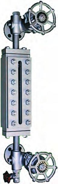
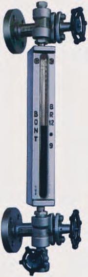
3 Glass Level Gauges General information CESARE Company has been manufacturing level gauges since their origin. This product has been our industrial speciality in Italy and all over the world since the twenties. This catalogue describes our glass level gauges, whereas our magnetic level gauges are shown in a separate bulletin. When you only state the operating conditions, namely: fluid working pressure working temperature we are able to supply the most suitable level gauge from both the points of view functionality and price. There are three basic types of glass level gauges: reflex transparent bicolour. reflex level gauges (Fig. 701) Working principle: The liquid level is distinguished by the different brightness of the reflex glass in the water or in the steam space. in fact, where there is liquid in contact the glass, the incidental light is refracted to the inside of the gauge and absorbed; in the steam space, the incidental light is reflected against the glass grooves and the glass appears very bright (Fig. 701). Applications: Reflex level gauges can be used in most of application and offer great advantages in terms of: low initial cost low operating cost easy level reading Reflex level gauges cannot be used in certain cases as for example: when the separation level between two liquids has to be read (interface); when besides the level indication, the observation of the liquid colour is required; when the process fluid is high-pressure water steam, since in this case the glass must be protected from the solvent action of the boiler water by using mica shields; when the process fluid is such that can corrode the glass (e.g. high temperature alkaline solutions or hydrofluoric acid), since mica shields or Polytrifluorochloroethylene shields must be used to protect the glass. transparent level gauges (Fig. 702 and 703) Working principle: Apart from glass tube level gauges, transparent level gauges are always fitted two plate transparent glasses between which the fluid is contained. The fluid level is indicated as the result of the different transparency of the two media (Fig. 702) and in some cases (for water steam), by conveying upwards on to the surface of separation (between liquid and gaseous substances) a source of light (Fig. 703) located at the back of the gauge, the rays of which are totally reflected down to the observer. Applications: Transparent level gauges are suitable for almost all installations. In fact they permit: the use of mica shields or Polytrifluorochloroethylene shields to protect the glass from the corrosive action of the process fluid; the observation of interface; the observation of the liquid colour. bicolour level gauges (Fig. 704) Working principle: The two opposite glasses fitted into these bicolour level gauges are not parallel to each other. By means of a suitable illuminator into which a red and a green screens are fitted, the portion of visible length occupied by steam appears red whereas the portion of visible length occupied by water appears green. The level reading is very easy even at a considerable distance. The reading of the bicolour level gauges is not affected by the blind spaces between one port-hole and the successive one (Fig. 704). Details on page Applications: Their main application is on high pressure steam boilers. bicolour level gauges parallel glasses (Fig. 812) Working principle: It is a variation of transparent level gauges, however equipped two reflex glasses and a back illuminator, fitted suitable coloured filters. The sharp reading is given by the contrast between the bright colour (usually: red) of filters in the lower part containing liquid and the colour of upper part of visible window (Fig. 812). Applications: These level gauges are particularly suitable for liquids: colourless, very fluid, non-corrosive for glasses (e.g. ammoniacal solutions, trichloroethylene, water steam up to 32 bar, etc.). Remote Reading Level Gauges, type ITT-RDR Now these level gauges are not frequently requested because Magnetic Remote Reading Level Gauges are preferred (specific bulletin on request). Nevertheless they are appreciated and we still produce them. The system includes: drum connections, condensate pot, downward connection pipes, operating device, down gauge body. Usually bodies type BT29 or BT33 are used. Further details on request. Request of Offer and Order The above descriptions are given as general information on the possible uses of level gauges. However the characteristics of the plant by same performances should guide the planner towards a well defined type of level gauge, that is most suitable for the purpose. Guide elements can be: pressure, temperature, colour, viscosity, density, corrosion power of the process fluid, environmental conditions as dangerous area, indoor or outdoor, corroding atmosphere, etc. Therefore when enquiring about level gauges or when placing order the following information must be supplied: type of the process fluid maximum working pressure maximum working temperature centre to centre distance between the vessel connections (or visible length required) type of connections (flanged, threaded, etc.) and standard (UNI, ASME, BS, DIN, AFNOR, GOST, etc.) according to which they are required optionals requested: see - page 27 for shut-off valves - page 37 for gauges bodies. Fig. 701 reflex Fig. 702 transparent Fig. 703 transparent Fig. 704 bicolour Fig. 812 bicolour 3
4 Glass Level Gauges Types, Material Schedules, Applications In this Bulletin we give the description of our level gauges made of metallic materials and omit that ones of nonmetallic materials (Ebonite, Polypropylene, PTFE, etc.): information on request. Fig. 864 Type Page Material Schedule Max operating conditions Press. Bar Temp. C Rating (**) ASME Class PN bar Fluid R e f l e x BR14 - GP11 6 BR 14 - G Water steam, other fluids BR12 - GP Water steam BR12 - G , (*) Other fluids (Remark 14) BR22 - GP Water steam BR22 - GP , (*) Other fluids (Remark 14) BR23 - GP Water steam BR23 - GP , 63, (*) Other fluids (Remark 14) BR24 - GP Water steam BR24 - GP , 63, 64 BR28 - G , 52, 63, 64 BR28 - GP , 63, 64 BR25 - GP , 63, (*) (*) (*) (*) Other fluids (Remark 14) Any fluids, water steam excepted (Remark 14) Any fluids, water steam excepted (Remark 14) Any fluids, water steam excepted (Remark 14) BR13 - G (2500) (400) Any fluids (Remark 9) T r a n s p a r e n t BR26 & BR , 55, 61, 62, 63, 64 BTV - GP , 63, (600) Any fluids, water steam excepted (Remark 10) Water steam (Remark 11) BT23 - GP Water steam (Remark 12) BT23 - GP , 63, (*) 300 Other fluids (Remark 14) BT24 - GP Water steam (Remark 12) BT24 - GP , 63, 64 BT25 - GP , 63, (*) (*) Other fluids (Remark 14) Any fluids, water steam excepted (Remark 14) BT28 - GP Water steam (Remark 12) BT28 - GP , 63, 64 BT29 - G , 63, (*) (*) Other fluids (Remark 14) Any fluids, water steam excepted (Remark 14) BT33 - G Water steam BT32 - G Water steam BT26 & BT , 55, 61, 62, 63, 64 (600) Any fluids, water steam excepted (Remark 10) Bicolour BC24 - GP Water steam BC28 - GP Water steam BC33 - G Water steam BC32 - G Water steam BC1 - G Water steam NOTE: (*) Maximum allowable temperature according to DIN 7081 / For operating condition temperature over 300 C, please apply to our Sales or Technical department. (**) The shown rating is an indication only: level gauge rating can change according the level gauge valve fitted on it. See also notes on page 5 and apply to us for further information 4
5 Fig. 706 Material Schedule Body and wetted pieces Trim of shut-off valves (Remark 8) Remarks Application 51 Forged carbon steel Stainless steel 52 Forged carbon steel Stainless steel 55 Forged carbon steel ASTM A350 LF2 Stainless steel AISI 316 Exclusion of copper, silver and their alloys Exclusion of copper, silver and their alloys General purpose Non corrosive fluids at low temperature up to 45,6 C ( 50 F) 61 Forged stainless steel AISI 304 Stainless steel AISI 316 External not wetted parts of stainless steel AISI 304 Corrosive fluids and/or fluids at temperature lower than 45,6 C ( 50 F) 62 Forged stainless steel AISI 304 Stainless steel AISI 316 External not wetted parts of carbon steel. Exclusion of copper, silver and their alloys. Corrosive fluids 63 Forged stainless steel AISI 316 Stainless steel AISI 316 External not wetted parts of stainless steel AISI 304 Corrosive fluids and/or fluids at temperature lower than 45,6 C ( 50 F) 64 Forged stainless steel AISI 316 Stainless steel AISI 316 External not wetted parts of carbon steel. Exclusion of copper, silver and their alloys. Corrosive fluids SPECIAL For some types of level gauges we have normally available components made of different nuances of AISI 316, Monel 400 (ASTM B164 - Class A), Hastelloy B, Hastelloy C, Incoloy 825, Carpenter 20 CB 3, Nickel, Titanium, Ebonite, PVC, Polypropylene, PTFE. Apply to us for other materials The tag indicating the type of the level gauge consists of two parts that define: the type of the level gauge body the type of the set of valves. The level gauges having their tag followed by a Z are special constructions. They are suitable for operating conditions different than the ones shown in Fig. 864 for the corresponding standard type. The nominal passage diameter in the level gauges is 10 mm, if not otherwise indicated. Only the gauge bodies type BR25 and BT25 have a large chamber 40 mm inside diameter and are usually used where the medium boils surges. The ASME ratings and the operating conditions shown in Fig. 864 refer to size 9. For smaller sizes the operating conditions an be higher. See diagrams on each description page or apply to us. The classification shown in the column «ASME ratings» could be modified by temperature operating condition, due to the maximum limit temperature suitable for the glass according DIN 7081/ As shown in the Table of Fig. 864 the maximum operating conditions are generally higher than those of ASME rating. Apply to us for further information. The ASME ratings and the operating conditions shown in Fig. 864 refer to standard materials as carbon steel, stainless steel, Hastelloy and to standard glass joints. When special materials (Monel, Nickel, Ebonite, PVC, etc.) and/or special joints (pure PTFE, Kel-F, etc.) are required, the maximum operating conditions have to be verified In Fig. 706 is indicated the material of the piston for the set of valves type GP11 and GP12. For a detailed list of material currently employed on shut-off valves, refer to tables shown on the pages illustrating the level gauges valves (from page 27 to page 33) For type BR13-G51, the ASME rating is an indication only. Types BR26, BR27, BT26, BT27 are manufactured for ASME 600 rating. Anyway the operating conditions must take into consideration the vessel project, the welding difficulties on the vessel of the level gauge body and especially that there are no shut-off fittings. The type BTV-GP11 is equipped a glass transparent tube. Because of its brittleness this level gauge can be used dangerless fluids only, although in presence of glass protector. In case the level gauge must be fitted directly on a steam boiler drum, please state it clearly. Most of Figures show the level gauges fitted the Sets type GP11, GP12 (Fig. 834 page 29). They can also be fitted Sets G41, G42, GS41, GS42 (see pages 30 and 31). In the latter case the level gauges identification tag changes after the hyphen, e.g. from BR24-GP11 to BR24-G41. The maximum operating conditions, ratings and applications are a function of the gauge body, therefore Fig. 864 and 706 are still valid. In case of fluid corrosive for the glass, please refer to our Technical department to define maximum allowable tempeature and glass protection. 7 In Fig. 706 are indicated the main Material schedules currently manufactured. Boldface are given the ones of major diffusion. 5
6 Reflex Level Gauges type BR14 GP11 and G11 valves Fig Type BR14-GP11 Length of glass length of body Visible length GP11 G11 Size G B V , , , , , , ,7 1 Connections between gauge and valves are made by end tues and stuffing boxes. 2 According to the position of the shut-off valves compared the gauge body, the level gauge is named right-handed or left-handed. Fig shows a left-handed gauge. Each level gauge can be assembled right-handed or left-handed. Usually two level gauges (1 right and 1 left) are installed on steam vessels. 3 According to some Steam Boiler Regulations, the visible length of the level gauges installed on steam boilers must be not shorter than a fixed length. Therefore the suitability of the smaller sizes must be checked. 4 When ordering a level gauge please state: Centre to centre distance between connections (CC) Standard, Size and Finishing of connections Whether right-handed or left-handed. 5 Flanges are finished to customer prescriptions. Please state: Standard Size Pressure class Finishing The inside passage through the gauge is 10 mm. 6 Instead of flanges, connections can be delivered threaded ends. Standard is 3/4 NPT, union. Other Standard and size on request. 7 BR14 gauges are fitted reflex glasses type A (see page 38). 8 Operating conditions and material schedules on pages 4 and 5. 9 Applicable optionals and bolting torques on pages 27, 36, 37. 6
7 Reflex Level Gauges type BR12 GP11, GP12, G11 and G12 valves Fig. 837 Type BR12-GP11 Size Length Length Visible of glass of body length GP11 GP12 G11 G12 G B V , , , , , , , ,2 2x ,2 2x ,8 2x ,7 2x ,6 2x ,6 2x x ,4 3x ,8 3x ,8 3x ,9 4x ,9 4x ,9 4x ,7 5x ,3 5x ,1 5x ,6 6x ,2 6x ,4 7x ,3 1 Connections between gauge and valves are made: - for BR12 GP11 or G11, by end tubes and stuffing boxes - for BR12 GP12 or G12, by NPT screwed nipples. 2 According to the position of the shut-off valves compared the gauge body, the level gauge is named right-handed or left-handed. Fig. 837 shows a left-handed gauge. Each level gauge can be assembled right-handed or left-handed. Usually two level gauges (1 right and 1 left) are installed on steam vessels. 3 According to some Steam Boiler Regulations, the visible length of the level gauges installed on steam boilers must be not shorter than a fixed length. Therefore the suitability of the smaller sizes must be checked. 4 When ordering a level gauge please state: Centre to centre distance between connections (CC) Standard, Size and Finishing of connections Whether right-handed or left-handed. 5 Flanges are finished to customer prescriptions. Please state: Standard Size Pressure class Finishing The inside passage through the gauge is 10 mm. 6 Instead of flanges, connections can be delivered threaded ends. Standard is 3/4 NPT, union. Other Standard and size on request. 7 BR12 gauges are fitted reflex glasses type A (see page 38). 8 Operating conditions and material schedules on pages 4 and 5. 9 Applicable optionals and bolting torques on pages 27, 36, Gauge bodies out valves can be supplied: end connected (threaded or flanged) side connected (threaded or flanged) back connected (threaded or flanged). Please state connecting dimensions and Standard. 7

8 Reflex Level Gauges type BR22 GP11, GP12, G41/42 and GS41/42 valves Fig Type BR22-GP11 Size Length of glass Length Visible of body length G B V GP11 GP12 G & GS 41 & 42 1 Connections between gauge and valves are made for BR22-GP11, by end tubes and stuffing boxes for BR22-GP12, by NPT screwed nipples for BR22-G41/42 & GS41/42, by NPT screwed nipples. Minimum CC distance, shown on table is referred to 1/2 NPT connections. On request 3/4 NPT connection can be supplied. 2 According to the position of the shut-off valves compared the gauge body, the level gauge is named right-handed or left-handed. Fig shows a left-handed gauge. Each level gauge can be assembled right-handed or left-handed. Usually two level gauges (1 right and 1 left) are installed on steam vessels. 3 According to some Steam Boiler Regulations, the visible ength of the level gauges installed on steam boilers must be not shorter than a fixed length. Therefore the suitability of the smaller sizes must be checked. 4 When ordering a level gauge please state: Centre to centre distance between connections (CC) Standard, Size and Finishing of connections Whether right-handed or left-handed. 5 Flanges are finished to customer prescriptions. Please state: Standard Size Pressure class Finishing The inside passage through the gauge is 10 mm. 6 Instead of flanges, connections can be delivered threaded ends. Standard is 3/4 NPT, union. Other Standard and size on request. 7 BR22 gauges are fitted reflex glasses type B (see page 38). 8 Operating conditions and material schedules on pages 4 and 5. Graph below shows rating for size 9 and smaller, combined included. 9 Applicable optionals and bolting torques on pages 27, 36, Gauge bodies out valves can be supplied: end connected (threaded or flanged) side connected (threaded or flanged) back connected (threaded or flanged). Please state connecting dimensions and Standard , , , , , , , , , , , , , , , , , ,4 2x , ,3 2x , ,8 2x , ,1 2x , ,5 2x , ,8 2x , ,2 3x , ,8 3x , ,4 3x , ,3 3x , ,9 4x , ,3 4x , ,9 4x , ,7 5x , ,2 5x , ,4 5x , ,4 6x , ,0 6x , ,2 7x , ,9 11 For level gauges type BR22-G41, BR22-G42, BR22-GS41, BR22-GS42, see page

9 Reflex Level Gauges type BR23 GP11, GP12, G41/42 and GS41/42 valves Fig Type BR23-GP11 Size Length Length Visible of of body length glass G B V GP11 GP12 G & GS 41 & 42 1 Connections between gauge and valves are made for BR23-GP11, by end tubes and stuffing boxes for BR23-GP12, by NPT screwed nipples for BR23-G41/42 & GS41/42, by NPT screwed nipples. Minimum CC distance, shown on table is referred to 1/2 NPT connections. On request 3/4 NPT connection can be supplied. 2 According to the position of the shut-off valves compared the gauge body, the level gauge is named right-handed or left-handed. Fig shows a left-handed gauge. Each level gauge can be assembled right-handed or left-handed. Usually two level gauges (1 right and 1 left) are installed on steam vessels. 3 According to some Steam Boiler Regulations, the visible length of the level gauges installed on steam boilers must be not shorter than a fixed length. Therefore the suitability of the smaller sizes must be checked. 4 When ordering a level gauge please state: Centre to centre distance between connections (CC) Standard, Size and Finishing of connections Whether right-handed or left-handed , , , , , , , , , , , , , , , , , ,1 2x , ,4 2x , ,9 2x , ,8 2x , ,4 2x , ,3 2x , ,3 3x , ,3 3x , ,1 3x , ,1 3x , ,6 4x , ,9 4x , ,9 4x , ,9 5x , ,7 5x , ,6 5x , ,2 6x , ,5 6x , ,4 7x , ,7 5 Flanges are finished to customer prescriptions. Please state: Standard Size Pressure class Finishing The inside passage through the gauge is 10 mm. 6 Instead of flanges, connections can be delivered threaded ends. Standard is 3/4 NPT, union. Other Standard and size on request. 7 BR23 gauges are fitted reflex glasses type B (see page 38). 8 Operating conditions and material schedules on pages 4 and 5. Graph below shows rating for size 9 and smaller, combined included. 9 Applicable optionals and bolting torques on pages 27, 36, Gauge bodies out valves can be supplied: end connected (threaded or flanged) side connected (threaded or flanged) back connected (threaded or flanged). Please state connecting dimensions and Standard. 11 For level gauges type BR23-G41, BR23-G42, BR23-GS41, BR23-GS42, see page

10 Reflex Level Gauges Type BR24 GP11, GP12, G41/42 and GS41/42 valves Fig Type BR24-GP11 Size Length Length Visible of of body length glass G B V GP11 GP12 G & GS 41 & , , , , , , , , , , , , , , , , , ,1 2x , ,6 2x , ,7 2x , ,5 2x , ,8 2x , ,7 2x , ,3 3x , ,4 3x , ,4 3x , ,1 3x , ,5 4x , ,1 4x , ,5 4x , ,6 5x , ,7 5x , ,0 5x , ,8 6x , ,4 6x , ,0 7x , ,1 1 Connections between gauge and valves are made for BR24-GP11, by end tubes and stuffing boxes for BR24-GP12, by NPT screwed nipples for BR24-G41/42 & GS41/42, by NPT screwed nipples. Minimum CC distance, shown on table is referred to 1/2 NPT connections. On request 3/4 NPT connection can be supplied. 2 According to the position of the shut-off valves compared the gauge body, the level gauge is named right-handed or left-handed. Fig shows a left-handed gauge. Each level gauge can be assembled right-handed or left-handed. Usually two level gauges (1 right and 1 left) are installed on steam vessels. 3 According to some Steam Boiler Regulations, the visible length of the level gauges installed on steam boilers must be not shorter than a fixed length. Therefore the suitability of the smaller sizes must be checked. 4 When ordering a level gauge please state: Centre to centre distance between connections (CC) Standard, Size and Finishing of connections Whether right-handed or left-handed. 5 Flanges are finished to customer prescriptions. Please state: Standard Size Pressure class Finishing The inside passage through the gauge is 10 mm. 6 Instead of flanges, connections can be delivered threaded ends. Standard is 3/4 NPT, union. Other Standard and size on request. 7 BR24 gauges are fitted reflex glasses type B (see page 38). 8 Operating conditions and material schedules on pages 4 and 5. Graph below shows rating for size 9 and smaller, combined included. 9 Applicable optionals and bolting torques on pages 27, 36, Gauge bodies out valves can be supplied: end connected (threaded or flanged) side connected (threaded or flanged) back connected (threaded or flanged). Please state connecting dimensions and Standard. 11 For level gauges type BR24-G41, BR24-G42, BR24-GS41, BR24-GS42, see page

11 Reflex Level Gauges type BR28 GP12, G41/42 and GS41/42 valves Fig. 856 Type BR28-G41 Size Length of glass Length of body Visible length G B V GP12 G & GS 41 & , , , , , , , , , , , , , , , , , ,1 2x , ,3 2x , ,7 2x , ,5 2x , ,1 2x , ,9 2x , ,7 3x , ,5 3x , ,4 3x , ,6 3x , ,3 4x , ,7 4x , ,3 4x , ,9 5x , ,0 5x , ,0 5x , ,5 6x , ,7 6x , ,1 7x , ,7 1 Connections between gauge and valves are made for BR28-GP11, by end tubes and stuffing boxes for BR28-GP12, by NPT screwed nipples for BR28-G41/42 & GS41/42, by NPT screwed nipples. Gauge/valve standard NPT connection is 1/2. On request3/4 NPT connection can be supplied. 2 According to the right of left position of the stop valves handle of the gauge body, the level gauges are named right handled or left-handed. Fig. 856 shows a left-handed level gauges. 3 When ordering a level gauge please state: Centre to centre distance between connections (CC) Standard, Size and Finishing of connections Whether right-handed or left-handed. 4 Flanges are finished to customer prescriptions. Please state: Standard Size Pressure class Finishing The inside passage through the gauge is 12,5 mm. 5 Instead of flanges, connections can be delivered threaded ends.it is standard 3/4 NPT union. 6 BR28 gauges are fitted reflex glasses type B (see page 38). 7 Operating conditions and material schedules on pages 4 and 5. Graph below shows rating for size 9 and smaller, combined included. 8 Applicable optionals and bolting torques on pages 27, 36, Gauge bodies out valves can be supplied: end connected (threaded or flanged) side connected (threaded or flanged) back connected (threaded or flanged). Please state connecting dimensions and Standard. 10 For level gauges type BR28-G42, BR28-GS41, BR28-GS42, see page

12 Reflex Level Gauges type BR25 GP12, G41/42 and GS41/42 valves Fig. 841 Type BR25-GP12 Size Length of glass Length of body Visible length G B V GP12 G & GS 41 & 42 1 Type BR25-GP12 level gauge is LARGE CHAMBERED. The gauge body is machined from a tube having thick wall and internal Ø of about 40 mm. Large chamber level gauges should be used where the medium boils or surges. 2 Connections between gauge and valves are made by NPT screwed nipples. Minimum CC distance, shown on table is referred to 1/2 NPT connections. On request 3/4 NPT connection can be supplied. 3 According to the position of the shut-off valves compared the gauge body, the level gauge is named right-handed or left-handed. Fig. 841 shows a left-handed gauge. Each level gauge can be assembled right-handed or left-handed. 4 When large chamber body is required butt-welding end caps, length of body (B) and minimum C. to C. (CC min) have to be increased of 40 mm. 5 When ordering a level gauge please state: Centre to centre distance between connections (CC) Standard, Size and Finishing of connections Whether right-handed or left-handed. 6 Flanges are finished to customer prescriptions. Please state: Standard Size Finishing Pressure class The inside passage through the gauge is 40 mm. 7 Instead of flanges, connections can be delivered threaded ends. Standard is 3/4 NPT, union. Other Standard and size on request. 8 BR25 gauges are fitted reflex glasses type B (see page 38). 9 Operating conditions and material schedules on pages 4 and 5. Graph below shows rating for size 9 and smaller, combined included. 10 Applicable optionals and bolting torques on pages 27, 36, Gauge bodies out valves can be supplied: end connected (threaded or flanged) side connected (threaded or flanged) back connected (threaded or flanged). Please state connecting dimensions and Standard , , , , , , , , , , , , , , , , , ,6 2x , ,0 2x , ,6 2x , ,2 2x , ,8 2x , ,3 2x , ,0 3x , ,7 3x , ,6 3x , ,8 3x , ,4 4x , ,4 4x , ,3 4x , ,8 5x , ,2 5x , ,9 5x , ,2 6x , ,4 6x , ,6 7x , ,0 12 For level gauges type BR25-G41, BR25-G42, BR25-GS41, BR25-GS42, see page
13 Reflex Level Gauges type BR13 G51 valves Fig. 857 Type BR13-G51 1 Connections between gauge and valves are made by flanges. Gauge body cannot be rotated on its axis. Other connections on request. 2 According to the right or left position of the handwheel of the stop valves on the gauge body, the level gauges are named right-handed or left-handed fig. 857 shows a right-handed level gauge. 3 When ordering a level gauge please state: - Centre to centre distance between connections (CC) - Standard. Size and Finishing of connections - Whether right-handed or left-handed. 4 Flanges are finished to customer prescriptions. Please state: Standard Size Pressure class Finishing The inside passage through the gauge is at least 12,5 mm. 5 Instead of flanges, connections to vessel can be delivered threaded ends or weld ends. 6 BR13 gauges are fitted reflex glasses type A-BR13 (see page 38), that ARE NOT COMPRESSED by the tightening screw. Joint Dimensions and Maintenance Instructions on request. 7 Operating conditions and material schedules on pages 4 and 5. 8 Applicable optionals and bolting torques on pages 27, 36, Gauge bodies out valves can be supplied: end connected (threaded or flanged) side connected (threaded or flanged) back connected (threaded or flanged). Please state connecting dimensions and Standard. Size Length of glass Length of body Visible length length G B V x x x x x x x x x x x x x x x x x x x
14 Reflex Level Gauges Weld - on Bodies, type BR26 and BR27 Fig. 717 Type BR26 Fig. 821 Type BR27 Length Length Visible Size of glass of body length BR26 BR27 G B V These gauge bodies are suitable for welding directly on the vessel. Therefore, no valves can be fitted between vessel and gauge, and incase of glass breakage, the fluid flowing from the vessel cannot be stopped. 2 It is necessary to control the suitability of the vessel wall, on which the gauge body is to be welded as this must not be excessively weakened by the holes or communicating window the gauge. Steel plates to strengthen the vessel wall should be used whenever this is possible. 3 During the welding operation, be careful to not expose the gauge body for long time to high temperatures, as this might damage the flatness of the glass sealing surface. 4 For BR26 the connecting lip is provided to facilitate the welding operation. 5 When enquiring or ordering BR27 please state the external radius (R) of the vessel on which the gauge must be welded. 6 For visible lengths over 320 mm two or more single gauge bodies will have to be welded on the vessel. In this case it is advisable to fit the gauge bodies not along the same vertical line, but offset. 7 BR26 and BR27 are fitted reflex glasses type B (see page 38). 8 Operating conditions and material schedules on pages 4 and 5. 9 Applicable optionals and bolting torques on pages 36,
15 Tubular glass Level Gauges type BTV-GP11 Fig. 842 Type BTV-GP11 Fig. 720 Fig. 721 Dimensions: Max C. to C. CC max = 2000 mm Glass tube length G = CC 28 mm Visible length V = CC 110 mm nearly 7,0 1 Type BTV-GP11 level gauges are equipped a transparent glass tube of 16 mm outside diameter. The limitation of the operating conditions is due to the glass tube, while the valves type GP11 are suitable for higher pressure and temperature. 2 As the glass tubes are usually found on sale up to a maximum standard length of about 2000 mm, when the centre to centre distance is longer than this size, the installation of several, cascade disposed level gauges or the application of an intermediate support stuffing-boxes are necessary. In the latter case the length of each glass tube will be half the centre to centre distance minus 17 mm. 3 To protect the glass tube against shocks we supply on request U shaped metallic protector (Fig. 720) to be fixed to the stuffing box gland and/or acrylic resin tube protector (Fig. 721) sealed by O-Rings to the stuffing box gland. 4 According to the position of the shut-off valves compared the gauge body, the level gauge is named right-handed or left-handed. Fig. 842 shows a left-handed gauge. Each level gauge can be assembled right-handed or left-handed. Usually two level gauges (1 right and 1 left) are installed on steam vessels. 5 When ordering a level gauge please state: Centre to centre distance between connections (CC) Standard, Size and Finishing of connections Whether right-handed or left-handed. 6 Flanges are finished to customer prescriptions. Please state: Standard Size Pressure class Finishing The inside passage through the gauge is 10 mm. 7 Instead of flanges, connections can be delivered threaded ends. Standard is 3/4 NPT, union. Other Standard and size on request. 8 BTV-GP11 gauges are fitted glass tubes having 16 mm outside diameter and length equal to the centre to centre distance minus 28 mm. 9 Operating conditions and material schedules on pages 4 and Applicable optionals on pages 27 and

16 Transparent Level Gauges type BT23 GP11, GP12, G41/42 and GS41/42 valves Fig Type BT23-GP11 Size Length Length Visible of of body length glass G B V GP11 GP12 G & GS 41 & , , , , , , , , , , , , , , , , , ,8 2x , ,3 2x , ,2 2x , ,8 2x , ,9 2x , ,1 2x , ,1 3x , ,7 3x , ,6 3x , ,8 3x , ,0 4x , ,3 4x , ,7 4x , ,6 5x , ,1 5x , ,6 5x , ,2 6x , ,5 6x , ,8 7x , ,3 1 Connections between gauge and valves are made for BT23-GP11, by end tubes and stuffing boxes for BT23-GP12, by NPT screwed nipples for BT23-G41/42 & GS41/42, by NPT screwed nipples. Minimum CC distance, shown on table is referred to 1/2 NPT connections. On request 3/4 NPT connection can be supplied. 2 According to the position of the shut-off valves compared the gauge body, the level gauge is named right-handed or left-handed. Fig shows a left-handed gauge. Each level gauge can be assembled right-handed or left-handed. Usually two level gauges (1 right and 1 left) are installed on steam vessels. 3 According to some Steam Boiler Regulations, the visible length of the level gauges installed on steam boilers must be not shorter than a fixed length. Therefore the suitability of the smaller sizes must be checked. 4 When ordering a level gauge please state: Centre to centre distance between connections (CC) Standard, Size and Finishing of connections Whether right-handed or left-handed. 5 Flanges are finished to customer prescriptions. Please state: Standard Size Finishing Pressure class The inside passage through the gauge is 10 mm. 6 Instead of flanges, connections can be delivered threaded ends. Standard is 3/4 NPT, union. Other Standard and size on request. 7 BT23 gauges are fitted transparent glasses type B (see page 38). 8 Operating conditions and material schedules on pages 4 and 5. Graph below shows rating for size 9 and smaller, combined included. 9 Applicable optionals and bolting torques on pages 27, 36, Gauge bodies out valves can be supplied: end connected (threaded or flanged) side connected (threaded or flanged) back connected (threaded or flanged). Please state connecting dimensions and Standard. 11 For level gauges type BT23-G41, BT23-G42, BT23-GS41, BT23-GS42, see page
17 Transparent Level Gauges type BT24 GP11, GP12, G41/42 and GS41/42 valves Fig Type BT24-GP11 Size Length Length Visible of of body length glass G B V GP11 GP12 G & GS 41 & , , , , , , , , , , , , , , , , , ,4 2x , ,5 2x , ,7 2x , ,0 2x , ,6 2x , ,2 2x , ,2 3x , ,5 3x , ,1 3x , ,1 3x , ,7 4x , ,8 4x , ,1 4x , ,8 5x , ,5 5x , ,1 5x , ,0 6x , ,1 6x , ,1 7x , ,3 1 Connections between gauge and valves are made for BT24-GP11, by end tubes and stuffing boxes for BT24-GP12, by NPT screwed nipples for BT24-G41/42 & GS41/42, by NPT screwed nipples. Minimum CC distance, shown on table is referred to 1/2 NPT connections. On request 3/4 NPT connection can be supplied. 2 According to the position of the shut-off valves compared the gauge body, the level gauge is named right-handed or left-handed. Fig shows a left-handed gauge. Each level gauge can be assembled right-handed or left-handed. Usually two level gauges (1 right and 1 left) are installed on steam vessels. 3 According to some Steam Boiler Regulations, the visible length of the level gauges installed on steam boilers must be not shorter than a fixed length. Therefore the suitability of the smaller sizes must be checked. 4 When ordering a level gauge please state: Centre to centre distance between connections (CC) Standard, Size and Finishing of connections Whether right-handed or left-handed. 5 Flanges are finished to customer prescriptions. Please state: Standard Size Pressure class Finishing The inside passage through the gauge is 10 mm. 6 Instead of flanges, connections can be delivered threaded ends. Standard is 3/4 NPT, union. Other Standard and size on request. 7 BT24 gauges are fitted transparent glasses type B (see page 38). 8 Operating conditions and material schedules on pages 4 and 5. Graph below shows rating for size 9 and smaller, combined included. 9 Applicable optionals and bolting torques on pages 27, 36, Gauge bodies out valves can be supplied: end connected (threaded or flanged) side connected (threaded or flanged) back connected (threaded or flanged). Please state connecting dimensions and Standard. 11 For level gauges type BT24-G41, BT24-G42, BT24-GS41, BT24-GS42, see page
18 Transparent Level Gauges type BT25 GP12, G41/42 and GS41/42 valves Fig. 845 Type BT25-GP12 Size Length of glass Length of body Visible length G B V GP12 G & GS 41 & , , , , , , , , , , , , , , , , , ,5 2x , ,8 2x , ,3 2x , ,8 2x , ,4 2x , ,1 2x , ,4 3x , ,4 3x , ,7 3x , ,8 3x , ,4 4x , ,1 4x , ,5 4x , ,2 5x , ,4 5x , ,2 5x , ,1 6x , ,9 6x , ,0 7x , ,9 1 Type BT25-GP12 level gauge is LARGE CHAMBERED. The gauge body is machined from a tube having thick wall and internal Ø of about 40 mm. Large chamber level gauges should be used where the medium boils or surges. 2 Connections between gauge and valves are made by NPT screwed nipples. Minimum CC distance, shown on table is referred to 1/2 NPT connections. On request 3/4 NPT connection can be supplied. 03 According to the position of the shut-off valves compared the gauge body, the level gauge is named right-handed or left-handed. Fig. 845 shows a left-handed gauge. Each level gauge can be assembled right-handed or left-handed. 4 When large chamber body is required butt-welding end caps, length of body (B) and minimum C. to C. (CC min) have to be increased of 40 mm. 5 When ordering a level gauge please state: Centre to centre distance between connections (CC) Standard, Size and Finishing of connections Whether right-handed or left-handed. 6 Flanges are finished to customer prescriptions. Please state: Standard Size Pressure class Finishing The inside passage through the gauge is 40 mm. 7 Instead of flanges, connections can be delivered threaded ends. Standard is 3/4 NPT, union. Other Standard and size on request. 8 BT25 gauges are fitted transparent glasses type B (see page 38). 9 Operating conditions and material schedules on pages 4 and 5. Graph below shows rating for size 9 and smaller, combined included. 10 Applicable optionals and bolting torques on pages 27, 36, Gauge bodies out valves can be supplied: end connected (threaded or flanged) side connected (threaded or flanged) back connected (threaded or flanged). Please state connecting dimensions and Standard. 12 For level gauges type BT25-G41, BT25-G42, BT25-GS41, BT25-GS42, see page


19 Transparent Level Gauges type BT28 GP11, GP12, G41/42 and GS41/42 valves Fig. 846 Type BT28-GP11 Size Length Length Visible of of body length glass G B V GP11 GP12 G & GS 41 & 42 1 Connections between gauge and valves are made for BT28-GP11, by end tubes and stuffing boxes for BT28-GP12, by NPT screwed nipples for BT28-G41/42 & GS41/42, by NPT screwed nipples. Gauge/valve standard NPT connection is 1/2. On request 3/4 NPT connection can be supplied. 2 According to the position of the shut-off valves compared the gauge body, the level gauge is named right-handed or left-handed. Fig. 846 shows a left-handed gauge. Each level gauge can be assembled right-handed or left-handed. Usually two level gauges (1 right and 1 left) are installed on steam vessels. 3 According to some Steam Boiler Regulations, the visible length of the level gauges installed on steam boilers must be not shorter than a fixed length. Therefore the suitability of the smaller sizes must be checked. 4 When ordering a level gauge please state: Centre to centre distance between connections (CC) Standard, Size and Finishing of connections Whether right-handed or left-handed , , , , , , , , , , , , , , , , , ,7 2x , ,9 2x , ,1 2x , ,5 2x , ,5 2x , ,9 2x , ,5 3x , ,3 3x , ,3 3x , ,4 3x , ,3 4x , ,1 4x , ,9 4x , ,1 5x , ,9 5x , ,4 5x , ,9 6x , ,9 6x , ,7 7x , ,5 5 Flanges are finished to customer prescriptions. Please state: Standard Size Pressure class Finishing The inside passage through the gauge is 10 mm. 6 Instead of flanges, connections can be delivered threaded ends. Standard is 3/4 NPT, union. Other Standard and size on request. 7 BT28 gauges are fitted transparent glasses type B (see page 38). 8 Operating conditions and material schedules on pages 4 and 5. Graph below shows rating for size 9 and smaller, combined included. 9 Applicable optionals and bolting torques on pages 27, 36, Gauge bodies out valves can be supplied: end connected (threaded or flanged) side connected (threaded or flanged) back connected (threaded or flanged). Please state connecting dimensions and Standard. 11 For level gauges type BT28-G41, BT28-G42, BT28-GS41, BT28-GS42, see page The BT28 gauge body can be fitted set of valves G42: this level gauge is called type BT28-G42 and is suitable for water steam up to 50 bar and 263 C. 19


20 Transparent Level Gauges type BT29 GP12, G41/42 and GS 41/42 valves Fig. 868 Type BT29-G41 Size Length of glass Length of body Visible length G B V GP12 G & GS 41 & , , , , , , , , , , , , , , , , , ,7 2x , ,9 2x , ,1 2x , ,5 2x , ,5 2x , ,9 2x , ,5 3x , ,3 3x , ,3 3x , ,4 3x , ,3 4x , ,1 4x , ,9 4x , ,1 5x , ,9 5x , ,4 5x , ,9 6x , ,9 6x , ,7 7x , ,5 1 Connections between gauge and valves are made for BT29-GP12, by NPT screwed nipples for BT29-G41/42 & GS41/42, by NPT screwed nipples. Gauge/valve standard NPT connection is 1/2. On request 3/4 NPT connection can be supplied. 2 According to the position of the shut-off valves compared the gauge body, the level gauge is named right-handed or left-handed. Fig. 868 shows a left-handed gauge. 3 When ordering a level gauge please state: Centre to centre distance between connections (CC) Standard, Size and Finishing of connections Whether right-handed or left-handed. 4 Flanges are finished to customer prescriptions. Please state: Standard Size Pressure class Finishing The inside passage through the gauge is 10 mm. 5 Instead of flanges, connections can be delivered threaded ends. Standard is 3/4 NPT, union. Other Standard and size on request. 6 BT29 gauges are fitted transparent glasses type B (see page 38). 7 Operating conditions and material schedules on pages 4 and 5. Graph below shows rating for size 9 and smaller, combined included. 8 Applicable optionals and bolting torques on pages 27, 36, Gauge bodies out valves can be supplied: end connected (threaded or flanged) side connected (threaded or flanged) back connected (threaded or flanged). Ple se state connecting dimensions and Standard. 10 For level gauges type BT29-G41, BT29-GS41, BT29-G42, BT29 GS42, see page


21 21
22 Transparent Level Gauges type BT33 G52 valves Fig. 858 Type BT33-G52 Size Length Length Visible of glass of body length length G B V , , , , , , ,5 2x ,9 2x ,5 2x ,1 2x ,7 2x ,2 2x ,0 3x ,2 3x ,6 3x ,9 3x ,5 4x ,5 4x ,5 4x ,0 5x ,3 5x ,1 5x ,5 6x ,7 6x ,9 7x ,4 1 Connections between gauge and valves are made by flanges and bolts. Provided valves are closed, gauge body can be easily rotated on its axis even boiler under steam in order to adjust easy reading from control floor. 2 According to the right or left position of the stop valves handle on the gauge body, the level gauges are named right-handed or left-handed. Fig. 858 shows a right-handed level gauge Usually two level gauges (1 right and 1 left) are installed on steam vessels. 3 According to some Steam Boiler Regulations, the visible length of the level gauges installed on steam boilers must be not shorter than a fixed length. Therefore the suitability of the smaller sizes must be checked. 4 For visible length over 320 mm we manufacture combined level gauges having two or more gauge bodies on common centre piece. Side gauge for by-passing blind distance is recommended (see Fig. 820, page 36). 5 When ordering a level gauge please state: Centre to centre distance between connections (CC) Standard, Size and Finishing of connections Whether right-handed or left-handed. 6 Flanges are finished to customer prescriptions. Please state: Standard Size Pressure class Finishing The inside passage through the gauge is at least 12.5 mm. 7 Instead of flanges, connections can be delivered welding ends (Socket welding or Butt welding). Please state connecting dimensions, size and Standard. 8 BT33 gauges are fitted transparent glasses type B (see page 38). 9 Operating conditions and material schedules on pages 4 and Applicable optionals and bolting torques on pages 27, 36, Gauge bodies out valves can be supplied: end connected (threaded or flanged) side connected (threaded or flanged) back connected (threaded or flanged). Please state connecting dimensions and Standard. 12 This level gauge is in compliance ASME Boiler - Section I requirements 22
23 Transparent Level Gauges type BT32 wit G52 valves Fig. 859 Type BT32-G52 Size Length Length Visible of glass of body length length G B V , , , , , , ,3 2x ,9 2x ,4 2x ,8 2x ,2 2x ,5 2x ,1 3x ,0 3x ,7 3x ,5 3x ,0 4x ,1 4x ,6 4x ,8 5x ,5 5x ,6 5x ,7 6x ,7 6x ,5 7x ,4 1 Connections between gauge and valves are made by flanges and bolts. Provided valves are closed, gauge body can be easily rotated on its axis even boiler under steam in order to adjust easy reading from control floor. 2 According to the right or left position of the stop valves handle on the gauge body, the level gauges are named right-handed or lefthanded. Fig. 859 shows a right-handed level gauge Usually two level gauges (1 right and 1 left) are installed on steam vessels. 3 According to some Steam Boiler Regulations, the visible length of the level gauges installed on steam boilers must be not shorter than a fixed length. Therefore the suitability of the smaller sizes must be checked. 4 For visible length over 315 mm we manufacture combined level gauges having two or more gauge bodies on common centre piece. Side gauge for by-passing blind distance is recommended (see Fig. 820, page 36). 5 When ordering a level gauge please state: Centre to centre distance between connections (CC) Standard, Size and Finishing of connections Whether right-handed or left-handed. 6 Flanges are finished to customer prescriptions. Please state: Standard Size Pressure class Finishing The inside passage through the gauge is at least 12.5 mm. 7 Instead of flanges, connections to the vessel can be delivered welding ends (Socket welding or Butt welding). Please state connecting dimensions, size and Standard. 8 BT32 gauges are fitted transparent glasses type B (see page 38). 9 Operating conditions and material schedules on pages 4 and Applicable optionals and bolting torques on pages 27, 36, Gauge bodies out valves can be supplied: end connected (threaded or flanged) side connected (threaded or flanged) back connected (threaded or flanged). Please state connecting dimensions and Standard. 12 This level gauge is in compliance ASME Boiler - Section I requirements 23

 on the front face of the gauges; an equal number of identical glasses on the back face of the gauge; 1 or more front covers and an equal number of back covers holding the glass")

24 Bicolour Level Gauges type BC24, BC28, BC33, BC32 Fig Type BC24 - BC28 Fig Type BC33 Fig Type BC32 Design and working principle bicolour level gauges are made of: 1 metallic centre piece containing steam and water of which level is to be measured; 1 or more flat transparent glasses (long or circular) on the front face of the gauges; an equal number of identical glasses on the back face of the gauge; 1 or more front covers and an equal number of back covers holding the glass assemblies against the centre piece; 1 illuminator case containing LED lamps of two colour (normally green and red); 1 set of shut-off valves for connection to boiler or tank. The bicolour level gauge has a trapezoidal body and consequently the front and the back glasses are non-parallel. They form a small angle. This special assembly and the different index of refraction of water and steam allows that the red and the green light of the illuminator entering the gauge passes through the gauge itself and is seen by the observer as follows: RED in correspondence of STEAM GREEN in correspondence of WATER. Application Bicolour level gauges are manufactured by our Company since more than 70 years. At the beginning only port-hole level gauges were produced (that is small circular glasses) suitable for high pressure water/steam, up to 225 bar (see level gauges type BC1-G55). For these severe conditions the small circular glasses are absolutely necessary and cannot be substituted by other types of glasses. In the recent year bicolour gauges have been very much appreciated because of the brilliant and sure reading they give and therefore they are more and more requested for low and medium pressure water/steam also, for which long glasses can safely be used. In case of combined level gauges, the bicolour reading it is not necessary to use side bodies for the uninterrupted visibility, allowing a simplification of the instrument. 24 For the same operating conditions, we produce both transparent and bicolour level gauges, (see Fig. 824, and 825.2). Dimensions (Body length, C to C Distance according to the different type of valve sets, etc.), Description and Maintenance Instructions of the Bicolour Level Gauges are identical to those of the corresponding Transparent Level Gauge. Bicolour Level Gauge Type Transparent Fig. 844 Max. Operating Contidions Pressure bar Temperature C Fluid BC24-GP11 BT24-GP Water steam BT24-GP11 Fig (*) Other fluids BC28-GP11 BT28-GP Water steam BT24-GP11 Fig (*) Other fluids BC33-G52 BT33-G Water steam Fig. 859 BC32-G52 BT32-G Water steam (*) NOTE: Maximum allowable temperature according to DIN 7081 / For operating condition temperature over 300 C, please apply to our Sales or Technical department.
25 Bicolour Level Gauges type BC1 G55 valves Fig. 860 Type BC1-G55 Size Number of portholes C. to C. distance Length of body Visible length CC min B V Longer or shorter visible length can be suppliede on request In particular the circular glasses appear: - RED in correspondence of STEAM - GREEN in correspondence of WATER The level can be: - read by observer standing directly IN FRONT of the level gauge, at the same height of body, or it can be outfitted : - special periscope mirrors able to transmit the signal to the control station by means of a simple periscopic arrangement mirrors. The mirrors (both top and bottom) adjustable to assist alignment, - closed TV circuit, also transmitting a 4 20 ma signal - Red Cherry optics-fiber system: this system can transmit the red and green light signal to the control station by means of fiber-optic remote viewing device. Ask for peculiar bulletin. Needs of each plant should be known before stating supplying 4 The standard illuminator is explosion-proof and consists of a stainless steel box containing red and green LED lamps, is suitable for the number of port holes and is suitable for V 50/60Hz or V DC power supply. The illuminator is slotted so as to fit into the level gauge centre piece. The red line of LED lamps must be placed in correspondence of the narrow side of the gauge body; the green line on the wide side. In this way the view of red steam and green water will be produced. We recommend to use only original illuminator as spare. 5 We manufacture BC1 gauges adequate number of port holes on one single centre piece. Shorter or longer visible length than those listed in the table can be supplied on request. 6 Centre to centre distance (CC) shown on table are referred to bodies holes having standard pitch of 73 mm. To meet special visibility request, different pitch length can be supplied. 1 According to the right or left position of the handwheel of the stop valves on the gauge body, the level gauges are named right-handed or left-handed. Fig. 860 shows a left-handed level gauge. Usually two level gauges (1 right and 1 left) are installed on steam vessel. 2 This level gauge consists of one gauge type BC1, and one set of valves type G55. It MUST be installed the gauge body in vertical position. G55 set is connected to a vertical pipe, which links upper and bottom gauge parts. It avoid condensate to flow through gauge body therefore granting better visibility and longer life of glasses. Gauge body is connected to pipe/valve assembly through two flanges and can be easily removed for inspection and service. 3 This gauge consists of a central body type BC1 and a certain number of covers attached to the front and the back of the body: the covers contain small circular glasses. Central body is manufactured of stainless steel for a longer life of the whole instrument. The illuminator is fitted and has bicolour LED lamps, half red and half green. The illumination of the gauge is based on the difference of refractive indexes of steam and water. The light source projects its rays through the adjacent coloured filter and in the steam and water spaces these coloured light rays are refracted to a different degree depending upon the refractive index of the medium. This permits only one colour of light to emerge from each medium, the other being absorbed in the wall of the gauge. 7 When ordering a level gauge please state: - Centre to centre distance between connections (CC) - Standard, Size and Finishing of connections - Whether right-handed or left-handed. 8 Flanges are finished to customer prescriptions. Please state: - Standard - Size - Pressure class - Finishing The inside passage through the gauge is at least 12,5 mm. 9 Instead of flanges, connections can be delivered welding ends (Socket welding or Butt welding). Please state connecting dimensions, size and Standard. 10 BC1 gauges are fitted transparent glass discs (Dia. 31,6 x 12,7 mm). Dimensions of joints and mica and Maintenance Instructions on request. 11 Operating conditions and material schedules on pages 4 and Applicable optionals and bolting torques on pages. 27 and Gauge bodies out valves can be supplied: end connected (threaded or flanged) side connected (threaded or flanged) back connected (threaded or flanged). Please state connecting dimensions and Standard. 14 This level gauge is in compliance ASME Boiler - Section I requirements 25
26 Transparent Level Gauges Weld - on Bodies, type BT26 and BT27 Fig. 734 Type BT26 Fig. 822 Type BT27 Size Length of glass Length of body Visible length BT26 BT27 G B V These gauge bodies are suitable for welding directly on the vessel. Therefore, no valves can be fitted between vessel and gauge, and in case of glass breakage, the fluid flowing from the vessel cannot be stopped. 2 It is necessary to control the suitability of the vessel wall, on which the gauge body is to be welded as this must not be excessively weakened by the holes or communicating window the gauge. Steel plates to strengthen the vessel wall should be used whenever this is possible. 3 During the welding operation, be careful to not expose the gauge body for long time to high temperatures, as this might damage the flatness of the glass sealing surface. 4 For BT26 the connecting lip is provided to facilitate the welding operation. 5 When enquiring or ordering BT27 please state the external radius (R) of the vessel on which the gauge must be welded. 6 For visible lengths over 320 mm two or more single gauge bodies will have to be welded on the vessel. In this case it is advisable to fit the gauge bodies not along the same vertical line, but offset. 7 BT26 and BT27 are fitted transparent glasses type B (see page 38). 8 Operating conditions and material schedules on pages 4 and 5. 9 Applicable optionals and bolting torques on pages 36,
27 Level Gauges Optionals for Sets of Valves Fig. 865 Set Valve Plug Top and bottom ball-check Operated by Heating Type Fig. top bottom drain vent drain vent handwheel chain double weighted handwheel lever lever external internal G S S S A A A A S NA A NA A NA G S S S A A A A S NA A NA A NA GP S S S A A A A S NA NA NA A NA GP S S S A A S A S NA NA NA A NA G S S A A A A S S NA A A A A G S S A A A A S S A A A A A GS S S A A A A S S NA A A A NA GS S S A A A A S S A A A A NA G S S S A NR NR A S A NA NA A NA G S S S A NR NR A S A NA NA A NA G S S S A NR NR A S A NA NA A NA Keys and Remarks to Fig. 865 S Standard Equipment A Applicable NA Not applicable NR Possible, but not recommended 1 We mean by Set the assembly of two valves (1 top and 1 bottom) for the connection of the gauge body to the vessel. The set stops fluid between vessel and level gauge in case of servicing. 2 This bulletin shows steel level gauges only; the sets fitted on the level gauges include the following patterns: - type G11 and G12, top and bottom: sleeve packed cocks; (see page 27) - type GP11 and GP12, top and bottom: piston valves; (see pages 28 and 29) - type G41 and G42, Offset metallic seating valves, stainless steel screwedin seat and stainless steel disk (see pages 30 and 31). - type GS41 and GS42, Straight metallic seating valves, stainless steel screwed-in seat and stainless steel disk (see pages 30 and 31). type G51, G52, G55, metallic seating valves, Stellite faced trim (see pages 32 and 33). 3 Each set is usually supplied or out some optionals according to its original design and its main application. 4 EXTERNAL HEATING has electrical or steam tracing, installed on job site. By INTERNAL HEATING gauge body is inside traced for heating fluid. 5 All sets can be supplied INTERMEDIATE SUPPORT fitted on the vessel in the middle between top and bottom valve in case of very large C. to C. distance. Intermediate support usually clamps the gauge bodies only and is not in connection the vessel inside. 6 Optionals for gauge bodies on pages 36 and 37. Gauge Valves General information These are the classical cocks for level gauges having a cylindrical plug soft tightening packing sleeve. The advantages of this design are: - circular through flow passage; - very long life of body and plug, since the elastic packing sleeve is interposed between this two pieces; - no sensitivity to changes of temperature; - no possible plug seizure; - best performance at high temperature; - possibility to restore tightness during service by compressing packing sleeve; - complete interchangeability of worn pieces. Offset Valves type G11 and G12 suitable for ASME 300 and PN 400 (type G11) suitable for ASME 900 and PN 160 (type G12) These set are suitable for: - type G11 (connection to gauge by stuffing box) Fig. 737; ASME Class 300 and PN 40 - type G12 (connection to gauge by screwed nipples) Fig. 738 ASME Class 900 and PN 160 Handles and plug are made so that each handle face downward when the gauge is in service, that is when shut-off (top and bottom) are open and drain cock is closed. According to the right or the left position of the shut-off cocks handle, the set (and therefore the level gauge) is named right handed or left handed. Fig Type G11/G12 Centre to Centre distance When these sets of cocks are chosen for the level gauge, the value of the minimum vessel C. to C. distance is given from the formula: - type G11: min. C. to C. = Length of body mm ( = B mm); exceptionally CC min = B + 92 mm - type G12: min. C. to C. 1/2 NPT nipples = Length of body + 50 mm (CC min = B + 50 mm) Optionals - Double ended handle for chain operating; - Automatic safety ball check removal device for bottom ball Please apply to our sales organisation for more details and technical Information. Connection Type G12 Connection Type G11 Top and bottom cock Drain cock 1 Body 21 Body 41 Connecting head 2 Plug 22 Plug 42 P16 packing ring 3 Tightening nut 23 Tightening nut 43 Stuffing box ring 4 Packing sleeve 24 Packing sleeve (16/23, 5/10) 2 eyelets, type M2.2 2 eyelets, type M Stuffing box nut 6 Ring 26 Ring 45 End tube 9 Handle* 29 Handle* 46 Tube joint ring 10 Screw and washer* 30 Screw and washer* 47 Drain joint ring 11 Head joint 31 Tailpipe joint 52 NPT nipple 12 Stud and nut 32 Tailpipe 54 NPT plug 33 Union nut * Items No. 9, 10, 29 and 30 are in Carbon steel also for Material Schedule 63 27
28 Gauge Valves Offset Valves type GP11 and GP12 suitable for ASME 300 and PN 400 (type GP11) suitable for ASME 900 and PN 160 (type GP12) Fig. 831 Fig. 832 Type GP11 Type GP12 General information General information These sets of valves consist usually of: 2 shut-off valves (1 top and 1 bottom) 1 drain valve. The advantages of this design are: excellent performance of Piston Valves, qualified according to: API 6 FA and BS 6775: Fire Safe TA Luft: German Clean Air, TÜV Mannheim Druckbehälterverordnung 22: for railway and road tankers down to 40 C, TÜV München easy servicing easy dismantling of the gauge body, to facilitate replacement of the glass. These sets are suitable for: type GP11 (Fig. 831): connection to gauge body by stuffing box ASME class 300 and PN 40 type GP12 (Fig. 832): connection to gauge body by screwed nipples - ASME class 900 and PN 160 Maximum service temperature: 425 C (797 F). According to the position of the shut-off valves compared the gauge body, the Set of valves (and therefore the level gauge) is named right-handed or left-handed. Fig. 831 shows a left-handed gauge. Each level gauge can be assembled right-handed or left-handed Connection to the vessel Can be: flanged to customer requirements. Please state: Standard Size Pressure class Finishing The flanges are integral the body. Different sizes and finishing of flanges can be obtained according to the most used international Standards (ASME, AFNOR, BS, DIN, GOST, UNI, etc.). screwed: 3/4 NPT Male Plain Union 3/4 NPT Male Spherical Union 3/4 NPT Male Integral welded: 3/4 Socket Welding other connections on request. Connection to the gauge body Can be: type GP11 (Fig. 831): connection by stuffing boxes and end tubes. type GP12: connection by NPT screwed nipples (Fig. 832). In both choices the connection is made by means of head-pieces (item 41 or 51) and allows easy dismantling of the gauges for servicing and easy rotating on its axis for the best reading, provided valves are closed even vessel under pressure. Centre to Centre distance When these sets of valves are chosen for the level gauge, the value of the minimum vessel C. to C. distance is given from the formula: type GP11: Minimum C. to C. = Body length mm (CC min = B mm) type GP12: Minimum C. to C. 1/2 NPT nipples = Body length + 81 mm (CC min = B + 81 mm) Fig. 833 Material Schedule Body and wetted parts Trim Remarks Application 52 Forged carbon steel ASTM A 105 Stainless steel 63 Forged stainless steel AISI 316 Stainless steel AISI Forged stainless steel AISI 316 Stainless steel AISI 316 Exclusion of copper, silver and their alloys. External not wetted parts of S.S. AISI 304 or 303. External not wetted parts of carbon steel. Exclusion of copper, silver and their alloys. General purpose Corrosive fluids and/or fluids at temperature lower than 29 C Corrosive fluids 28
29 Fig. 834 GP11 GP12 Fig. 866 Part Material for Material Schedule Item Part Upper and Lower Valve 1 Body ASTMA105 ASTM A182 F316 ASTM A182 F Lower Valve Ring Graphite St. St. Graphite St. St. Graphite St. St.l 2,2 Upper Valve Ring Graphite St. St. Graphite St. St. Graphite St. St. 3 Lantern Bush Carbon Steel ASTM A479 T316 ASTM A479 T316 4 Piston ASTM A479 T316 ASTM A479 T316 ASTM A479 T316 6 Spindle ASTM A479 T410 ASTM A479 T304 ASTM A479 T410 7 Handwheel Aluminium Aluminium Aluminium 8 Handwheel Nut Carbon Steel Carbon Steel Carbon Steel 9 Bonnet ASTM A105 ASTM A182 F316 ASTM A Stud Bolt and Nut A193 B7 - A194 2H A193 B8 - A194 G8 A193 B7 - A194 2H 11 Washer Carbon Steel Carbon Steel Carbon Steel 12 Stud Bolt and Nut A193 B7 - A194 2H A193 B8 - A194 G8 A193 B7 - A194 2H 14 Gasket Asbestosfree Asbestosfree Asbestosfree Drain Valve 21 Body ASTM A105 ASTM A182 F316 ASTM A182 F Valve Ring Graphite St. St. Graphite St. St. Graphite St. St. 23 Bonnet ASTM A105 ASTM A182 F316 ASTM A Needle ASTM A479 T410 ASTM A479 T316 ASTM A479 T Screw A193 B7 A193 B8 A193 B7 27 Handwheel Aluminium Aluminium Aluminium 28 Handwheel Nut Carbon Steel Carbon Steel Carbon Steel 41 Head GP11 ASTM A105 ASTM A479 T316 ASTM A479 T Packing Ring Graphite St. St. Graphite St. St. Graphite St. St. 43 Stuffing Box Ring Carbon Steel. ASTM A479 T316 ASTM A479 T Stuffing Box Nut Carbon Steel ASTM A479 T316 Carbon Steel Optionals Vent Plug on the upper head-piece (standard for GP12) Vent Valve on the upper head-piece Automatic Safety Ball-Check, in the upper and lower valve External tracing for heating or cooling, by electrical wire or pipe (to be made on field) Intermediate support not connected the vessel, for very long C. to C. distance. Material Schedules Standard Material Schedules as per Fig Other Material Schedules available on request. Parts material is listed on Fig Request or Order Please state: type of set: Code GP11 or GP12 right-handed or left-handed connections to the vessel: to be detailed optionals, if any Material Schedule: Fig. 833 Service Before the valves are put in service: shut off the upper and lower valve and lightly follow up the bonnet Nuts (10) open the drain valve and lightly follow up the bonnet Screws (25) follow up the Gaskets (14) by the Nuts (12). Spare parts One complete set of sealing elements for 1 level gauge consists of: 5 Valve Rings (item ) B 10 x B 18 x 6 2 Gaskets (item 14) B 20 x B 10,5 x 1 2 Packing Rings (item 42) B 16 x B 23,5 x 5, for GP11 only. 51 Head GP12 ASTM A105 ASTM A479 T316 ASTM A479 T NPT Vent Plug Carbon Steel ASTM A479 T316 ASTM A479 T316 29
30 Gauge Valves General information These sets of valves are designed and manufactured expressly for use level gauges and pressure gauges up to ASME 1500 and PN 250. For use water steam, we recommend the type GS42 and G42, outside screw and yoke. These valves have bolted bonnet and metallic trim renewable seat. The valves are available: OFFSET Inside Screw (Fig. 747) Code G41 Outside Screw and Yoke(Fig. 748) Code G42 STRAIGHT Inside Screw (Fig. 854) Code GS41 Outside Screw and Yoke (Fig. 855) Code GS42 They are both suitable for ASME 1500 and PN The Body is of drop forged steel. - The Bonnet is of drop forged steel and of the same material as body. It is bolted to the body by means of four bolts nut. The advantages of this design are quite obvious, respect to a bonnet screwed into the body or to a bonnet connected to the body by means of studs. - The Disk is integral on the Stem, is made of stainless steel AISI 316 and is backseating against the bonnet when the valve is full open, for easy repacking under pressure.. - The Seat is of stainless steel AISI 316 (Monel or special material on request) and is easy renewable, being screwed into the body. - One Safety Ball-Check of stainless steel AISI 316 (special material on request) is fitted to both valves as standard, for safety in the event of glass breakage. The safety ball is removed from its seat during the closing operation of the valve by means of the Stem extremity. - The Packing is made of an adequate number of preformed rings of an approved high pressure - temperature quality. Special material on request. - The Name Plate bears all prescribed indications and is fixed on each valve. - For Operating three solutions are available: - Handwheel for plain-closing stem Code 1 - ed lever for quick-closing stem Code 2 - Double-ended lever for quick-closing stem Code 3 Connections to the vessel Can be: - flanged: integral flange up to 125 mm o.d. (standard) weld-on flange for major o.d. Please state: - Standard - Pressure class - Size - Finishing - screwed: 3/4 NPT male union (standard) 3/4 NPT male union spherical, 3/4 NPT male integral. - welded: 3/4 socket welding - other connections on request. Connections to the gauge body Can be: - screwed 1/2 NPT female for nipple (standard) Code 4 - screwed 3/4 NPT female for nipple, - socket welding 1/2 or 3/4 - union tailpipe 1/2 NPT male and union nut (standard) Code 5 - stuffing box for glass tube 16 mm. o.d. Code 6 Length of glass tube must be 21 mm. shorter than the Centre to Centre distance Set of Valves type G41, G42, GS41, GS42 suitable for ASME 1500 and PN 250 Centre to Centre distance When these sets of valves are chosen for the level gauge, the value of the minimum vessel C. to C. distance is given by tables for each level gauge type, provided that the connection between the level gauge and its valves is obtained by means of 1/2 NPT screwed nipples. The min. C. to C. distance is given from the formula: - Minimum C. to C. 1/2 NPT nipples = Body length + 90 mm (CC min = B + 90 mm) - If tailpipe connection 1/2 NPT and Union nut is requested, 50 mm must be added to the minimum CC length. - Minimum C. to C. 3/4 NPT nipples becomes 30 mm longer. Connection to drain and vent Can be: - screwed 1/2 NPT female (standard) Code 7 - screwed 3/4 NPT female, - other connections on request. Optionals (see also page 29) - For Heating or Cooling the valves are available internal tube (only G41 and G42). - For Very Low Temperature the inside screw valves (type G41 and GS41) are available prolonged stem. Material Schedules Material Schedules currently manufactured on Fig Other Material Schedules other materials on request. Part material is listed on Fig Request or Order Please state - OFFSET, inside screw Code G41 - OFFSET, outside screw Code G42 - STRAIGHT, inside screw Code GS41 - STRAIGHT, outside screw Code GS42 - Operating Code 1 or 2 or 3 - Connections to the vessel to be detailed - Connections to gauge body Code 4 or 5 or 6 - Connections to drain and vent Code 7 - Material Schedule Code 52 or 55 or 63 - Centre to Centre distance to be stated Code When these sets are chosen our standard variants, the use of our Code is recommended. For instance: - 1 Set of valves inside screw OFFSET Code G41 operated by handwheel 1 connections to gauge body screwed 1/2 NPT female. 4 connections to drain and vent 1/2 NPT female. 7 material schedule 52 Resulting CODE: G It is to be stated in detail: - connections to the vessel, - Centre to Centre distance. Maintenance These sets don t need any special maintenance. We only recommend to check from time to time the tightening of Packing gland (45) and of body-bonnet Bolts (5). - other connections on request. Fig. 745 Type G41 and GS41 Fig. 746 Type G42 and GS42 30
31 Fig. 749 Material Schedule Body bonnet and wetted parts Trim and Ball-check Remarks Application 52 Forged carbon steel ASTM A105 Stainless steel AISI 316 Exclusion of cooper silver and their alloys General purpose 55 Forged carbon steel ASTM A350 LF2 Stainless steel AISI 316 External not wettedparts of S.S.AISI 304 or 303 Non corrosive fluids at low temperature up to 45,6 C ( 50 F). 63 Forged stainless steel AISI 316 Stainless steel AISI 316 External not wetted parts of S.S. AISI 304 or 303 Corrosive fluids and/or fluids at temperature lower than 45,6 C ( 50 F) Fig. 747 Type G41 (offset 20 mm) Fig Type GS41 (straight) Type GS42 (straight) Fig. 748 Type G42 (offset 20 mm) Note: remaining parts identical to: - Fig. 747 for GS41 - Fig. 748 for GS 42 Fig. 750 Item Part Materials for Material Schedule Item Part Materials for Material Schedule Body ASTM A105 ASTM A350 LF2 S.S. AISI Nipple Carbon steel S.S. AISI 316 S.S. AISI Seat S.S. AISI 316 S.S. AISI 316 S.S. AISI Nut Carbon steel S.S. AISI 303 S.S. AISI Ball-check S.S. AISI 316 S.S. AISI 316 S.S. AISI Union tailpipe Carbon steel S.S. AISI 316 S.S. AISI Bonnet joint ring Soft iron S.S. AISI 316 S.S. AISI Joint ring Suitable compressed material 5 Bolt ASTM A193 B7 S.S. AISI 303 S.S. AISI Nut ASTM A194 2H S.S. AISI 303 S.S. AISI Stem S.S. AISI 316 S.S. AISI 316 S.S. AISI Bottom ring Carbon steel S.S. AISI 316 S.S. AISI Bonnet ASTM A105 ASTM A350 LF2 S.S. AISI Packing Preformed rings Preformed rings Preformed rings 33 Bonnet flange ASTM A105 ASTM A350 LF2 S.S. AISI Handwheel Carbon steel Carbon steel Carbon steel 34 Gland Carbon steel S.S. AISI 304 S.S. AISI ed lever Carbon steel Carbon steel Carbon steel 35 Gland nut Carbon steel S.S. AISI 304 S.S. AISI Double-ended lever Carbon steel Carbon steel Carbon steel 10 Name plate Stainless steel Stainless steel Stainless steel 41 Stem S.S. AISI 316 S.S. AISI 316 S.S. AISI Washer Carbon steel Carbon steel Carbon steel 42 Stem bush S.S. AISI 410 S.S. AISI 410 S.S. AISI Nut ASTM A194 2H S.S. AISI 303 S.S. AISI Bonnet ASTM A105 ASTM A350 LF2 S.S. AISI Taper plug (on request) Carbon steel S.S. AISI 316 S.S. AISI Packing gland Carbon steel S.S. AISI 304 S.S. AISI Union nut Carbon steel S.S. AISI 303 S.S. AISI Bolt ASTM A193 B7 S.S. AISI 303 S.S. AISI Union tailpipe Carbon steel S.S. AISI 316 S.S. AISI Nut ASTM A194 2H S.S. AISI 303 S.S. AISI Joint ring Suitable compressed material 31
32 Gauge Valves Set of Valves type G51, G52, G55 suitable for ASME 2500 and PN 400 General information These sets of valves consist of metallic seating valves. Each set is generally composed by: - 2 shut-off valves sized 1 (1 top and 1 bottom) - 1 drain valve sized 1/2. The Set of valves fully comply the main international Standard and specifically ASME Code Section I, when applicable. The shut-off valves are bonnetless type, operated by handwheel rising non-rotating stem and stroke indicator. - The Body (1) is forged of carbon steel or stainless steel and is the only valve part under pressure. Seat is integral of Stellite deposited highly specialized and automatic procedure. The Backseat ring (46) is threaded into the body and can be easily replaced. - The Yoke (2) is always forged and is standard of carbon steel, has structural functions only and is not under pressure. Threaded outside the body and kept in place by means of one welding tack that can be easily removed and remake for inspection or maintenance. - The Disk (3) is of alloy steel whit seating surface Stellite. When backseated, disk is pulled against bonnet axial (not rotating) movement. - The Stem (4) is of stainless steel, heat treated. Threads are ACME. Being designed rising and non-rotating insures a lower driving and closing torque and less wear of packing rings. - The Yoke Bushing (11) is usually of special aluminium bronze and is kept in place by two Antifriction Rings (43) and form a Locking Ring (39). - The Packing includes one Bottom Ring (5), one Graphite Packing (6), one Packing Flange (10), two Swing Bolts (8) turning for easier repacking. - The Safety Ball-check (80) are in stainless steel AISI 316 and tighten on a seat made of stainless steel AISI 316. Connection to the gauge body Can be: - type G51 (Fig. 861, 857): flanged on the side of the gauge body, - type G52 (Fig. 862, 858, 859): flanged on the axis of the gauge body, - type G55 (Fig. 863, 860): flanged the interposition of a water column, - different connections can be delivered, according to customer prescription. Connection to the drum Can be: - Flanged: - The flange is always wekded to the valve body. Please specify Standard, Rating and Size - SW: - Please specify Standard, Rating and Size - BW - Please specify Standard, Rating and Size - Screwed: - Please specify Standard, Rating and Size Fig. 863 Top Valve Type G55 Fig. 867 Item Part 1 Body ASTM Stellite Gr. 6 Part Material for Material Schedule ASTM A182 F316 + Stellite Gr. 6 ASTM A182 F316 + Stellite Gr. 6 2 Yoke ASTM A105 ASTM A105 ASTM A105 3 Disk ASTM A479 T.316 ASTM A479 T.316 ASTM A479 T Stem ASTM A182 F6 ASTM A564 T.630 ASTM A564 T Bottom ring ASTM A479 T.316 ASTM A479 T.316 ASTM A479 T Packing Graphite Graphite Graphite 8 Swing bolt ASTM A193 B7 ASTM A193 B7 ASTM A193 B8 9 Pin Alloy steel Alloy steel Alloy steel 10 Packing flange ASTM A105 ASTM A182 F316 ASTM A182 F Yoke bushing ASTM B150 - C62300 ASTM B150 - C62300 ASTM B150 - C Handwheel Carbon steel Carbon steel Carbon steel 14 Disk pad ASTM A182 F6 Stainless steel + treatment Stainless steel + treatment 15 Handwheel nut Carbon steel Carbon steel Carbon steel 15A Bolt nut ASTM A194 2H ASTM A194 2H ASTM A194 Gr Name plate Stainless steel Stainless steel Stainless steel 23 Antirotation / indicator Carbon steel. + Zincplating Carbon steel. + Zincplating Stainless Steel 39 Locking ring ASTM A105 ASTM A105 ASTM A Retaining ring Alloy steel Alloy steel Alloy steel 43 Antifriction washer Carbon steel C70 Carbon steel C70 Carbon steel C70 46 Backseat ring ASTM A564 T.630 ASTM A564 T.630 ASTM A564 T Gasket Graphite Graphite Graphite 70 Connecting ring Stellite Stellite Stellite 80 Safety ball ASTM A479 T.316 ASTM A479 T.316 ASTM A479 T Bottom taper plug for ball ASTM A105 ASTM A479 T.316 ASTM A479 T Top taper plug for ball ASTM A105 ASTM A479 T.316 ASTM A479 T Welded nipple ASTM A105 ASTM A479 T.316 ASTM A479 T Connecting flange ASTM A105 ASTM A105 ASTM A479 T Lenticular joint ring ASTM A479 T.316 ASTM A479 T.316 ASTM A479 T Joint ring Graphite Graphite Graphite Bottom Valve 32
33 Optionals (see also page 29) Following optionals can be supplied: - Vent valve on top valve, - Safety ball-check on bottom valve, vertical, - Safety ball-check on top valve, horizontal removal device. Maintenance These sets of valves do not need particular maintenance. We would suggest to use good quality packings in the stuffing-box and to follow up the bolts of the packing gland from time to time. Material Schedules (see Fig. 867) Material Schedules currently manufactured on Fig Other materials on request. Fig. 861 Type G51 Top and bottom Valve Fig. 862 Type G52 Top Valve Bottom Valve 33
34 Level Gauges Reflex Gauge Bodies Description and Maintenance Instructions Bolting torques - Type BR14 30 Nm - Type BR24 40 Nm - Type BR12 50 Nm - Type BR25 40 Nm - Type BR22 30 Nm - Type BR26-BR27 40 Nm - Type BR23 40 Nm - Type BR28 50 Nm 1 Centre piece 8 Gauge body 2 Sealing joint 9 Wedge piece 3 Reflex glass 10 Tightening bolt 4 Cushion joint 11 Bolt nut 5 Cover plate 12 Clamp 6 U stud bolt nuts 13 Angular piece 7 O stud bolt nuts Fig. 817 Type BR14 Fig. 816 Type BR12 Fig. 760 Type BR22 Fig. 761 Type BR23 Fig. 762 Type BR24 Fig. 819 Type BR28 Fig. 763 Type BR25 Service maintenance Before putting in service, check the bolting torque as recommended on top of this page. Tighten the bolts alternatively, starting from centre of gauge. To avoid glass thermal shocks during start-up, the gauge temperature must gradually increase in order to allow both the metallic structure and the glass to reach the operating temperature. Proceed as follows: close bottom shut-off valve, completely open drain, partially open top shut-off valve to allow a minimum flow outlet of steam. Maintain flow outlet until proper temperature is reached, then close drain valve; the condensate coming through top valve will fill the gauge column. At this step completely open very slowly bottom shut-off valve, then completely open top shut-off valve. In case during operation fluid impurities affect glass, proceed to gauge washing as above described Important notice Maintenance must be made immediately when: - leakage appears, even if very small. In this case: shut of and cool down the gauge. Tighten the gauge nuts at the recommended bolting torque; - the glass appears opaque or slightly white specially in the steam area; - grooves of the reflex glass show sign of corrosion and/or erosion and the reading of the level is not clear. The lack of maintenance and the lack of replacement of the deteriorated parts can cause the breakage of the glass all the relevant consequences. Dismantling - Shut off the valves, let out the pressure and remove the level gauge body from the valves Loosen the tightening bolts and remove all component pieces. - Clean the sealing and cushion surfaces very carefully, making sure that they are clear of any remnants of joints. - Smear the threads of the tightening bolts a thin layer of graphite grease; Reassembling - Fit in a new glass new joints (never re-use joints which have already been in service!): remember that the sealing joint must be placed on the side where the grooves are. - Reassemble all the components in the right sequence. Tighten the bolts alternatively, starting from centre of gauge. - Never grip the level gauge body in a vice during the reassembling, but put it on a plane surface. - Never use adhesive or hermetic mastic. Remember that all surfaces must be perfectly clean. Spare parts - When ordering spare parts please state: - type and size of the gauge body - item number of the spare part, as shown in the above list - construction material. - As regards reflex glasses and their joints, please remember that: - each type BR12, BR14 gauge is fitted 1 reflex glass type A (section 30x17 mm), - each type BR22, BR23, BR24, BR25, BR28 gauge is fitted 1 reflex glass type B (section 34x17 mm). For type BR13, separate instructions on request.
35 Level Gauges Transparent Gauge Bodies Description and Maintenance Instructions Bolting torques - Type BT23-BC23 40 Nm - Type BT28-BC28 60 Nm - Type BT24-BC24 40 Nm - Type BT29 70 Nm - Type BT25 40 Nm - Type BT32-BC32 90 Nm - Type BT26-BT27 40 Nm - Type BT33-BC33 80 Nm 1 Centre piece 6 Cover plate 2 Sealing joint 7 Bolt nut 3 Glass protection sheet 8 Stud bolt nut (where applicable) 9 Stud nut 4 Plate glass 13 Angular Piece 5 Cushion joint 14 Belleville Washer Fig. 764 Type BT23 Fig. 765 Type BT24 Fig. 766 Type BT25 Fig. 767 Type BT28 & BT29 Fig Type BT33 Fig Type BT32 Service maintenance Before putting in service, check the bolting torque as recommended on top of this page. Tighten the bolts alternatively, starting from centre of gauge. To avoid glass thermal shocks during start-up, the gauge temperature must gradually increase in order to allow both the metallic structure and the glass to reach the operating temperature. Proceed as follows: close bottom shut-off valve, completely open drain, partially open top shut-off valve to allow a minimum flow outlet of steam. Maintain flow outlet until proper temperature is reached, then close drain valve; the condensate coming through top valve will fill the gauge column. At this step completely open very slowly bottom shut-off valve, then completely open top shut-off valve. In case during operation fluid impurities affect glass or protection shield, proceed to gauge washing as above described Important notice Maintenance must be made immediately when: - leakage appears, even if very small. In this case: shut of and cool down the gauge. Tighten the gauge nuts at the recommended bolting torque; - the glasses appear opaque or slightly white specially in the steam area; - the reading of the level is not clear. The lack of maintenance and the lack of replacement of the deteriorated parts can cause the breakage of the glasses all the relevant consequences. Dismantling - Shut off the valves, let out the pressure and remove the level gauge body from the valves. - Loosen and take out the tightening bolts and remove all component pieces as well. - Clean the sealing surfaces of the centre piece and the cushion surfaces of the cover plates very carefully, making sure that they are clear of any remnants of joints. - Smear the threads a thin layer of graphite grease. Reassembling - Fit in new glasses new joints (never re-use joints which have already been in service!). Remember that the glass protection sheet must be in direct contact the inner side of the glasses (between the glass and the fluid), and that the sealing joint must be placed on the sealing surface of the centre piece. Reassemble all the other components in the right sequence, and tighten the bolts alternatively, starting from centre of gauge. - Never grip the level gauge body in a vice during the reassembling, but put it on a plane surface. - Never use adhesive or hermetic mastic. Remember that all surfaces must be perfectly clean. Spare parts - When ordering spare parts please state: - type and size of the gauge body - item number of the spare part, as shown in the above list - construction material. - As regards plate glasses their joints and protection sheets, remember that each level gauge is fitted 2 plate glasses type B (section 34x17 mm). For type BC1 (bicolour), separate instructions on request. 35


 - low energy consumption: <8 W for each")
, - ATEX (II 2G Ex d mb IIC T6 - II 2D Ex tb IIIC T70 C IP66) -")

 or transparent level gauges. Fig. 820 - Combined level gauge uninterrupted visible length.")

36 Level Gauges Optionals for Gauge Bodies Fig. 773-Remark 7 Fig. 826 Illuminator type GSI Fig.870 LED Illuminator type LS & LX Fig. 827 Illuminator type EXGSI Fig.776 Fig. 828 Illuminator type EXPIN Fig. 820 Fig. 869 Fig LED Illuminators Tipe LS & LX Those new illuminators are supplied as standard. They can be supplied white light for transparent level gauges or red & green light for bicolour level gauges. Special colours (as fully blue or fully red or fully green etc.) upon request. The advantages of such illuminators are: - competitive price and very low LCC (Life Cycle Cost) - low energy consumption: <8 W for each meter lenght - small size and light weigth - long life (up to 100,000 hours = 10 years of continuous working) - vibrations proof - easy wiring: 110/230 50/60Hz or 18/36 Vdc - approvals: - CE (LVD & EMC), - ATEX (II 2G Ex d mb IIC T6 - II 2D Ex tb IIIC T70 C IP66) - on board transformer: - Type LS: 110/230V > 24V - 8W/mt, - Type LX: 110/230V > 24V - 8W/mt, ATEX II 2G Ex d mb IIC T6 - II 2D Ex tb IIIC T145 C IP66, - junction box EExd ¾ NPT-F connection - working temperature from -40 C up to 80 C - IP65 protection as standard - IP66 upon request Fig Non-frosting block for reflex level gauge. Fig Level gauge external heating or cooling tube. Can be supplied for reflex (as in figure) or transparent level gauges. Fig Combined level gauge uninterrupted visible length. Reflex (as in figure) or transparent. Fig Calibrated scale. The standard calibrated scale is in stainless steel, calibration in cm. On request, any different material or calibration can be supplied. Note: Illuminators Type GSI (Fig not explosion-proof), EXGSI (Fig explosion-proof), EXPIN (Fig for diffused lighting, explosion-proof), EXGSIBC and EXBSIN (explosion proof for bicolour level gauges) are out of production, but can be supplied as spares upon request. 36
37 Level Gauges Optionals for Gauge Bodies - Bolting Torques Fig. 777 Type of glass Accessories Type of Gauge A Reflex Transparent Glass Protection B A-BR13 Tube B Disk Non frosting blocks Heating or cooling internal external internal external Applicable i lluminator Graduated Scale Floats Uninterrupted visible length Bolting Torque Nm each Bolt Mica Kel-F Remark 7 Remark Remark 9 Remark 9 Fig. 775 BR14 X NA NA NA NA NA NA 1 A NA NA 30 BR 12 X NA NA NA NA NA NA 1 A NA NA 50 BR22 X NA NA NA NA A A 1 A NA A 30 BR23 X NA NA V A A A 1 A NA A 40 BR24 X NA NA V A A A 1 A NA A 40 BR28 X NA NA V A A A 1 A NA A 50 BR25 X NA NA V A A A 1 A NA A 40 BR13 X NA NA NA A A NA 1 A NA NA (Remark 8) BR26 X NA NA V A A NA 1 A NA NA 40 BR27 X NA NA V A A NA 1 A NA NA 40 BTV X NA NA R NA A NA 1 A A BT23 X A A V A A A 2, 3, 6 A A A 40 BT24 X A A V A A A 2, 3, 6 A A A 40 BT25 X A A V A A A 3, 6 A A A 40 BT28 X A A V A A A 2, 3, 6 A A A 60 BT29 X A A V A A A 2, 3, 6 A A A 70 BT33 X A A V A A A 2, 3, 6 A A A 80 BT32 X A A V A A NA 2, 3, 6 A A A 90 BT26 X A A V A A NA 1 A NA NA 40 BT27 X A A V A A NA 1 A NA NA 40 BC23 X C NA NA NA NA NA 4, 5, 6 NA NA NA 40 BC24 X C NA NA NA NA NA 4, 5, 6 NA NA NA 40 BC28 X C NA NA NA NA NA 4, 5, 6 NA NA NA 60 BC32 X C NA NA NA NA NA 4, 5, 6 NA NA NA 90 BC 1 X C NA NA NA NA NA 4, 5, 6 NA NA NA (Remark 8) Keys and Remarks to Fig. 777 X Type of glass fitted in the gauge. A Applicable. C Compulsory. NA Not applicable R V Recommended U shape metallic protector (Fig. 720) and/ or acrylic resin tube protector sealed by O-Rings to the stuffing box gland (Fig. 721). External glass protection (sheet of mica or Kel-F) may be suggested for protecting the glasses from corrosive environmental (see page 38). 1 Often not necessary. If necessary any usual lighting apparatus can be utilised. Apply to our Technical Service for details. 2 Apparatus for lighting of the meniscus at water level from lower position, not explosion-proof (Fig. 870). Type LED-LS. 3 Apparatus for lighting of the meniscus at water level from lower position, explosion-proof (Fig. 870). Type LED-LX. 4 Apparatus for lighting bicolour level gauges, not explosion-proof (Fig. 870), Type LED-LS 5 Apparatus for lighting bicolour level gauges, explosion-proof (Fig. 870), Type LED-LX 6 Illuminators Type GSI (Fig not explosion-proof), EXGSI (Fig explosion-proof), EXPIN (Fig for diffused lighting, explosion-proof) are out of production, but can be supplied as spares upon request. 7 Non-frosting blocks:.for reflex gauge and for transparent gauge (Fig. 773) for transparent level gauges an illuminator (Fig. 870) can also be fitted. Recommended height of blocks, see page See specific instructions. 9 Other optionals: Engraved scales to customer requirements. Mirrors to transmit image below to the observer. Closed circuit television equipment, which allows level reading on monitor in the control room and/or transmit a 4 20 ma signal. Fibre optic remote viewing device to transmit image in the control room, by means of our Red Cherry System. Ask for peculiar bulletin. Specific gravity glass floats can be provided in a transparent level gauge where the interface between two immiscible liquids is to be observed. Additional side connected bodies (reflex or transparent) to reach un-interrupted visible length (Fig. 820) Heating or cooling tracing tubes for reflex or transparent gauges (Fig. 776). For very long C to C distance, an intermediate support ( communicating the vessel) can be fitted to the level gauge body. 37
38 Sight Glasses for Level Gauges Standards and Quality Glasses fitted in our level gauges and spare glasses comply the following Standards: - DIN ONORM M MIL G B - TGL OMV H Esso Eng. Spec BS JIS B S.O.D. Spec. 123 Physical and chemical features: - Resistance to bending strain: >150 N/mm2 - Mean coefficient of linear expansion (30 C to 300 C): 5, K-1 - DIN Transition temperature: 550 C - DIN Hydrolytic resistance: Class 1 - DIN and ISO Alkali resistance: Class 2 - DIN and ISO Acid resistance: Class 1 - DIN Material is always borosilicate glass pre-stressed and optically tested. Pre-Stressed, hardened, extra hard and similar definitions are perfectly equivalent. We never use soda-lime glasses, since they have quite insuffi-cient features. Special attention shall be paid to length, width, thickness and especially flatness tolerances. From the latter point of view BONET- TI sight glasses have very strict tolerance values, definitely lower than most of the ones on the market. What above ensures less stress and longer life of glass and joints. Reflex or transparent glasses There are two types of sight glasses: Reflex Glass These glasses have both smooth faces. For application transparent level gauges. Transparent glasses have following dimensions: Size Type A Type B Type A-BT12 Length Width Thickn. Length Width Thickn. Length Width Thickn. L B S L B S L B S ,6 16, ,6 16, ,6 16, ,6 16, ,6 16, ,6 16, ,6 16,8 - Sizes of glasses are now indicated by Arabic numerals (1, 2, etc.). Former size indication was in Roman numerals (I, II, etc.). - Transparent glasses Type A (cross section 30 x 17 mm) are only spare parts for old pattern level gauges manufactured by us before Transparent glasses type A-BT12 are only spare parts for transparent bodies type BT12, no more in production. A special transparent glass is the round glass for application high pressure (usually bicolour) level gauges. This glass is a small disc (Fig ) very strict tolerances. Fig Fig. 801 These glasses have one smooth face (external face) and the other face provided moulded prismatic grooves (internal face). For application reflex level gauges. Reflex glasses have following dimensions: Size - Sizes of glasses are now indicated by Arabic numerals (1, 2, etc.). Former size indication was in Roman numerals (I, II, etc.). - Former size indication was in Roman numerals (I, II, etc.). Transparent Glasses Fig. 802 Type A Type B Type A-BR13 Length Width Thickn. Length Width Thickn. Length Width Thickn. L B S L B S L B S Joints for glasses - Each sight glass is usually supplied 2 joints (1 sealing joint + 1 cushion joint). - Length and width of joint are the same as those of the respective glass. - Reflex glasses type A-BR13 - for fitting in reflex gauges type BR13 - need special sized joints. See maintenance instructions. - Transparent glasses type A-BT12 - for fitting in transparent gauges type BT12, no more in production - need special sized joints. See maintenance instructions. Protection for glasses When glass protection against corrosive fluids is to be taken in consideration (including boiler water pressured over 35 bar), you must remember that only smooth surfaces can be shielded by smooth sheets having same length and width as sight glass. Therefore: - reflex glasses: only external face can be shielded by mica sheets or other materials against corrosive environmental agents, - transparent glasses: both faces can be shielded by mica or transparent polytrifluorochloroethylene (Kel-F) sheets. Protection of the internal glass face in contact fluid is usually sufficient. Mica sheets inside level gauges are always recommended for application water steam: thickness of mica sheets is usually 0.15 to 0.20 mm. Non-frosting Blocks Frost on gauge obstructing level reading could develop when level gauge operates at fairly low temperature. In such cases non-frosting block of transparent acrylic resin must be fastened and sealed outside the gauge body. This block shall protrude according to the thickness of the frost (see Fig. 773 and 829). Recommended protrusion: Working temperature of fluid Protrusion of block 120 C through 19 C 38 mm 20 C through 49 C 75 mm 50 C through 99 C 150 mm 100 C and lower 200 mm 38
39 C F C F C F C F bar C Conversion Table from C to F , Pressure/Temperature Table for Saturated Water Steam 1,0 99,1 1,5 110,7 2,0 119,6 2,5 126,7 3,0 132,8 3,5 138,1 4,0 142,9 4,5 147,2 5,0 151,1 5,5 154,7 6,0 158,0 6,5 161,1 7,0 164,1 7,5 167,1 8,0 169,6 8,5 172,2 9,0 174,5 9,5 176, , , , , , , , , , , , , , , , , , , , , , , , , , , , , , , , , , , , , , , , , , , , , , , , , , , , , , , ,0 39
 E-mail: italia@bont.")
 E-mail: armaturen@bonetti.")


40 Garbagnate Milanese (MI) Italy Limburg an der Lahn Germany Suzhou, Jiangsu China Karambele - Gujarat India CESARE S.p.A. Uff. vendite: Tel: Fax: Garbagnate Milanese (Italy) italia@bont.it Via Cesare Bonetti 17 Export sales: Tel: Fax: Internet web site: export@bont.it Armaturen GmbH & Co. KG Sales office: Tel: Fax: D Limburg an der Lahn (Germany) armaturen@bonetti.de In den Fritzenstücker, 4 Internet web site: (Suzhou) Level Gauges & Valves Co., Ltd. Sales office: Tel: Fax: No 8, Lane 1, Wupu Road, Shengpu District, bonettisuzhou@cesare-bonetti.cn Suzhou Industrial Park, Jiangsu, China Internet web site: WAAREE India Pvt., Ltd. Sales office: Tel: Fax: Survey No. 36, 39 & 42 - Karambele, Umergaon bonetti-india@waaree.com Valsad District Gujarat - India Internet web site: Tel.: This catalogue is exclusive property of Cesare Bonetti S.p.A. Any unauthorized reproduction, in total or in part, of this catalogue shall be prosecuted. Products and data sheets on this catalogue reflect current standard production. Cesare Bonetti S.p.A. reserves the right to carry out necessary amendments to products and materials. Amendments or modifications to drawings and materials can be done also to comply particular Customer's request or technical specifications. Pubblicazione B Rev.00 - Eng
Bulletin B Reflex Transparent Bicolour
 Bulletin B 06-09 GLASS LEVEL GAUGES Reflex Transparent Bicolour INDEX Page Page General Information...3 Bicolour Level Gauges type BC24, BC28, BC33, BC32 with GP11, GP12, G41, G42, GS41 & GS42...24 type
Bulletin B Reflex Transparent Bicolour
 Bulletin B 06-09 GLASS LEVEL GAUGES Reflex Transparent Bicolour Glass Level Gauges General information CESARE BONETTI Company has been manufacturing level gauges since their origin. This product has been
Process Level Gauges. Instrumentation Division
 Process Level Gauges Instrumentation Division We produce level gauges to suit virtually any application, available in single or multi-sections, with a variety of shut-off valves, cocks and accessories.
GLASS LEVEL GAUGES. Everywhere liquid levels have to be directly read and defined
 GLASS LEVEL GAUGES Everywhere liquid levels have to be directly read and defined Glass level gauges were invented and patented in 1888 by Richard Klinger, the founder of the Group of independent KLINGER
NARVIK-YARWAY. High Pressure Level Gauges, Model: 17
 NARVIK-YARWAY Narvik-Yarway covers requirements for level gauges and electronic water level systems with a wide range of models, sizes and materials to satisfy all the specifications of the power and process
1 TRANSPARENT LEVEL GAUGE
 SIGHT LEVEL GAUGES Index 1 Transparent level Gauge...01 2 Reflex Level Gauge...02 3 Tubular Level Gauge...03 3.1 Technical Specifications...03 4 Sight Level Indicator...04 4.1 Construction & Operation...04
KLINGER. Instructions for installation and operation of. Reflex level gauges K D asbestos-free. wt 3017/11 Page 1.
 Page 1 Instructions for installation and operation of KLINGER Reflex level gauges K D asbestos-free Edition: 06/2003 Fluid Control GmbH Am Kanal 8-10 A-2352 Gumpoldskirchen/AUSTRIA Telefon:++43(0) 2252
GLASS LEVEL GAUGES. Everywhere liquid levels have to be directly read and defined
 GLASS LEVEL GAUGES Everywhere liquid levels have to be directly read and defined Glass level gauges were invented and patented in 1888 by Richard Klinger, the founder of the Group of independent KLINGER
Valves. External Valves, Gages and Fittings. Bulletin No What options are available when stainless steel is not suitable for external parts.
 External Valves, Gages and Fittings Bulletin No. 218 What options are available when stainless steel is not suitable for external parts. Unless otherwise specified, the external valves, gages, fittings
AEGIS RSS Series. Fully Lined Bellows Sealed Control Valves. RSS Series
 Fully Lined Bellows Sealed Control Valves Corrosion-resistant PFA lining ISO/DIN and ANSI/ISA face-to-face Heavy-duty Paraflon bellows Special designs for chlorine and high-purity media ASSOCIATE CHLORINE
DURABILITY & PRECISION
 DURABILITY & PRECISION Flat Glass Gauges & Valves for Process Level Measurement by KEnco Featuring New Reflex & Transparent Armored Level Gauges Engineered Liquid Level Solutions www.kenco-eng.com FLAT
2/2-way Angle Seat Valve, manually operated, for media up to +180 C
 2/2-way Angle Seat Valve, manually operated, for media up to +180 C Position indication Adjustable flow rates Stainless steel valve body Compact industrial design with long service life /2702 can be combined
RAIMONDI. High pressure forged globe valves to guarantee the pressure envelope integrity on harsh services.
 Fig. 6022-6025 RAIMONDI High pressure forged globe valves to guarantee the pressure envelope integrity on harsh services. Features Forged body materials of highest quality, all in compliance with ASME
IN-LINE DISC & PISTON VALVES
 ID & IP Series IN-LINE DISC & PISTON VALVES PROCESS VALVES IN-LINE DISC & PISTON VALVES M Seal In-Line Piston Valve Code: IPYM Large valves utilize a non-rising stem to minimize overall length Live loaded
VD SERIES VESSEL & REACTOR VALVES DISC VALVES
 VD SERIES VESSEL & REACTOR VALVES DISC VALVES FULL FLOW BOTTOM OUTLET VALVES TANK BOTTOM DISC VALVE CODE: VD4R-VD6R M Ring for high temperature and vacuum. Other sealing systems are available Optional
contents MALLEABLE PIPE FITTINGS BUsHEs NiPPlEs PlUgs caps BENds BackNUTs UNioNs TEEs 171 cross PN25 p socket PN25 p socket PN25 p.
 contents BUsHEs 140 Hexagon Bush p.5 NiPPlEs 144 octagon Nipple p.6 145 Hexagon Nipple p.6 PlUgs 146 Beaded Plug - solid p.7 147 Plain Plug - Hollow p.7 148 Plain Plug - solid p.7 149 countersunk Plug
NELES HIGH PERFORMANCE TRIPLE ECCENTRIC DISC VALVE, METAL SEATED NELDISC SERIES L12
 NELES HIGH PERFORMANCE TRIPLE ECCENTRIC DISC VALVE, METAL SEATED NELDISC SERIES L12 Metso's Neles Neldisc series L12 a wafe type, metal seated high performance triple eccentric disc valve. With close to
Integral bonnet valves, steel bodies, stainless steel trim; wide choice of connections
 NORTHEAST CONTROLS INC. TEL: 201-327-7660 FAX: 201-327-3242 www.nciweb.com GAGE COCKS CONNECTION UN~IO~N~~~~EII~= Section: J100 Bulletin: J100.50 Date: 6/05 Supercedes: 1/99 Specialists in Liquid Level
RUBBER SLEEVE KNIFE GATE VALVE
 RUBBER SLEEVE KNIFE GATE VALVE The model knife gate is a bi-directional wafer valve equipped with two metallic coved rubber sleeves designed for use in the handling of abrasive slurries, mainly in industries
Technical changes kept in reserve WAFER STYLE KNIFE GATE VALVE. DN 50 to DN 250: 10 kg/cm² DN 300 to DN 400: 6 kg/cm²
 WAFER STYLE KNIFE GATE VALVE The A model knife gate is an uni-directional wafer valve designed for general industrial service applications. The design of the body and seat assures non-clogging shut off
ALC-3 BUTTERFLY VALVES NOMINAL PRESSURE NOMINAL SIZE MATERIALS CONNECTIONS DESIGN. ANSI Class PN DN
 BUTTERFLY VALVES ALC-3 NOMINAL PRESSURE ANSI Class 150-600 PN 10-100 NOMINAL 2-80 DN 50-2000 MATERIALS Cast Iron Carbon Steel Low Alloy Steel CONNECTIONS Wafer Lugged Flanged Butt Weld DESIGN Eccentric
PISTON DIVERTER VALVES
 DP Series DIVERTER VALVES PISTON DIVERTER VALVES PROCESS VALVES STRAHMAN DEAD SPACE FREE DIVERTER VALVES Piston Diverter Valves Code: DPS4 Standard branch angles: 45 o and 90 o 60 o and specific angles
WAFER STYLE KNIFE GATE VALVE
 11 WAFER STYLE KNIFE GATE VALVE The model knife gate is an uni-directional wafer valve designed for general industrial service applications. The design of the body and seat assures non-clogging shut off
WEDGE & SLAB GATE VALVES
 GW & GS Series GATE VALVES WEDGE & SLAB GATE VALVES PROCESS VALVES WEDGE GATE AND SLAB GATE VALVES FOR SPECIAL APPLICATIONS Wedge gate Valves Code: GW2M Hand wheel for small sizes Large size valves have
IN THIS CHAPTER-6 M-1
 IN THIS CHAPTER-6 We introduce all types of magnetic float type level gauges as standard model and more details for the float dimensions will be indicated in the submittal drawings because those are various
2/2-way Angle Seat Valve, manually operated, for media up to +180 C
 2/2-way Angle Seat Valve, manually operated, for media up to +180 C Position indication Adjustable flow rates Stainless steel 316L valve body Compact industrial design with long service life /2702 can
RUBBER SLEEVE KNIFE GATE VALVE
 RUBBER SLEEVE KNIFE GATE VALVE The model knife gate is a bi-directional wafer valve equipped with two metallic coved rubber sleeves designed for use in the handling of abrasive slurries, mainly in industries
ENGINEERED LIQUID LEVEL SOLUTIONS DURABILITY AND DEPENDABILITY FLAT GLASS GAUGES & VALVES FOR PROCESS LEVEL MEASUREMENT BY KENCO
 ENGINEERED LIQUID LEVEL SOLUTIONS DURABILITY AND DEPENDABILITY FLAT GLASS GAUGES & VALVES FOR PROCESS LEVEL MEASUREMENT BY KENCO FLAT GLASS GAUGES KENCO Flat Glass Gauges are used where direct visual observation
Keystone WINN Hi-Seal High Performance Butterfly Valve
 m o Keystone WINN Hi-Seal High Performance Butterfly Valve Hi-Seal, high performance butterfly valves offer efficient, bi-directional sealing across a wide spectrum of service conditions Features Positive
WAFER STYLE KNIFE GATE VALVE
 WAFER STYLE KNIFE GATE VALVE The model knife gate is an uni-directional wafer valve designed for general industrial service applications. The design of the body and seat assures non-clogging shut off on
Butterfly valves. Technical features 11 Coupling 12 Elements list 12 Tables 13 torque values 13 dimensions 15
 TT series valve TT Series 1 technical data 1 components DN 50-300 Stainless steel disc Stainless steel + PTFE disc 3 components DN 350-500 Tables 5 dimensions 5 torque values Installation instructions
ID & IP SERIES IN-LINE DISC AND PISTON VALVES
 ID & IP SERIES IN-LINE DISC AND PISTON VALVES IN-LINE DISC AND PISTON VALVES M SEAL IN-LINE PISTON VALVE CODE: IPYM Large valves utilize a non-rising stem to minimize overall length Live loaded packing
HD series. HD Series 1 technical data 1 components DN RTFE seat 2 Inconel seat 3 "FIRE SAFE" seat 4
 HD series double eccentric HD Series 1 technical data 1 components DN 50-300 2 RTFE seat 2 Inconel seat 3 "FIRE SAFE" seat 4 tables dimensions 5 torque values 6 pressure / temperature 6 tests 6 Gearboxes
WAFER STYLE KNIFE GATE VALVE
 WAFER STYLE KNIFE GATE VALVE The EX(SER.10) model knife gate is an uni-directional wafer valve designed for general industrial service applications. The design of the body and seat assures non-clogging
Globe Valve Type Fig. 1 Type 3241 Globe Valve. Mounting and Operating Instructions EB EN
 Globe Valve Type 3241 Fig. 1 Type 3241 Globe Valve Mounting and Operating Instructions EB 8015-1 EN Edition July 2012 Contents Contents Page 1 Design and principle of operation.................... 4 2
Type Pressure Transmitter with display. Pressure Transmitter. Technical data. DN15-50 Body material. Stainless steel 316L Actuator material
 2/2-way Angle Seat Valve, manually operated, for media up to +180 C Position indication Adjustable flow rates Stainless steel 316L valve body Compact industrial design with long service life Excellent
Technical changes kept in reserve THROUGH CONDUIT KNIFE GATE VALVE
 Technical changes kept in reserve THROUGH CONDUIT KNIFE GATE VALVE The B model knife gate is a bi-directional wafer valve designed for media with high consistency. The double seat design assures a non-clogging
Bicolour level gauge. Type BU green/red. D-04-B EN-1 Edition 05/11
 Bicolour level gauge Type BU green/red D-04-B-16615-EN-1 Edition 05/11 -itable of contents- 1. Health and safety instructions 4-5 1.1 General health and safety instructions...4 1.2 Unit-specific safety
HOPPER SHAPE KNIFE GATE VALVE
 HOPPER SHAPE KNIFE GATE VALVE The C model knife gate is a uni-directional wafer valve designed for industrial bulk handling service applications (powdered and granular products). makes it ideal for use
WAFER STYLE KNIFE GATE VALVE
 MODEL WAFER STYLE KNIFE GATE VALVE The model knife gate is an uni-directional wafer valve designed for general industrial service applications. The design of the body and seat assures non-clogging shut
TRANSPARENT LEVEL GAUGES
 TRANSPARENT LEVEL GAUGES Technical Information October 2008 International Headquarters Subsidiary for BENELUX INTRA-AUTOMATION GmbH B.V. INTRA-AUTOMATION HTP Otto-Hahn-Str. 20 Bosschendijk 193 41515 Grevenbroich
Worcester 18/19 Series. Modular Multi-Way Ball Valves
 Worcester 18/19 Series Modular Multi-Way Ball Valves The Modular Approach To Flexibility 2 Flowserve Worcester's modular Series 18/19 multi-way valve addresses the need for diverting media through a number
METSO NELES HIGH PERFORMANCE VALVE, METAL SEATED SERIES BW
 METSO NELES HIGH PERFORMANCE VALVE, METAL SEATED SERIES BW Neles BW series metal seated high performance butterfly valve with one piece body design, for both control and tight shut-off applications. Multiple
HOPPER SHAPE KNIFE GATE VALVE
 HOPPER SHAPE KNIFE GATE VALVE The model knife gate is a uni-directional wafer valve designed for industrial bulk handling service applications (powdered and granular products). The special design of the
Diaphragm Valve, Metal
 Diaphragm Valve, Metal Construction The GEMÜ piston actuated 2/2-way diaphragm valve is designed for use in sterile areas of application. All metallic actuator components are made of stainless steel. The
RUBBER SLEEVE KNIFE GATE VALVE
 RUBBER SLEEVE KNIFE GATE VALVE The model knife gate is a wafer valve designed for a wide range of industrial applications. The double-seated design provides bi-directional shut off. The design of the valve
Angle Seat Globe Valve, Metal
 Angle Seat Globe Valve, Metal Construction The GEMÜ manually operated 2/2-way angle seat globe valve has an ergonomically designed plastic handwheel. The valve spindle is sealed by a self-adjusting gland
CATALOG. Actuated Diaphragm Valve DN PVC-U / PVC-C / PP-H / PVDF / ABS SMART IN FLOW CONTROL.
 CATALOG Actuated Diaphragm Valve DN 15-100 PVC-U / PVC-C / PP-H / PVDF / ABS SMART IN FLOW CONTROL. TABLE OF CONTENTS Type 186 - DN 12-15 (MA 10) 04 General information - Technical specification 04 Sectional
THROUGH CONDUIT KNIFE GATE VALVE. OBX 09/11 2nd EDITION Revision 1 Reserves the right to change specifications without notice
 THROUGH CONDUIT KNIFE GATE VALVE The model knife gate is a bi-directional wafer valve designed for media with high consistency. The double seat design assures a non-clogging shut off on either normal or
Mounting and Operating Instructions EB 8091 EN. Pneumatic Control Valve Type and Type Type with 120 cm 2 actuator
 Pneumatic Control Valve Type 3510-1 and Type 3510-7 Type 3510-1 with 120 cm 2 actuator Type 3510-7 with 120 cm 2 actuator and integrated positioner Type 3510-1 with 60 cm 2 actuator Fig. 1 Pneumatic control
S GATE KNIFE GATE VALVE WITH PNEUMATIC ACTUATOR
 MAIN FEATURES The pneumatic S GATE knife gate valve is intended for the automatic shut off of pipes of the heavy fluids like slurries and powders. The main fields of application are the water treatment,
AKG-A/AKGS-A Type Series Booklet
 Gate Valve AKG-A/AKGS-A PN 63-160 DN 80/80-300/250 Type Series Booklet Legal information/copyright Type Series Booklet AKG-A/AKGS-A All rights reserved. The contents provided herein must neither be distributed,
Kovinska tesnila KLINGER
 procesna oprema Spiral Wound Gaskets Kovinska tesnila KLINGER Metallic Maxiprofile METALLIC GASKETS Maxiflex Introduction to Maxiflex... 42 Maxiflex Styles... 44 Graphite Filled... 46 PTFE Filled... 47
ptfe seated 30 years of high quality experience
 ptfe seated BUTTERFLY VALVES ed TT Series 1 technical data 1 components DN 50-300 Stainless steel disc Stainless steel + PTFE disc 3 tables components DN 350-500 dimensions 5 torque values 6 Installation
LIQUIDLINE PROGRAM. Connections for cooling water. dezincification-resistant brass. Messing. aluminium.
 LIQUIDLINE PROGRAM Connections for cooling water dezincification-resistant brass Messing aluminium stainless steel 2 Quality solutions - Made by EISELE EISELE IS QUALITY MADE IN GERMANY Over 30 patents,
Angle Seat Globe Valve, Metal
 Angle Seat Globe Valve, Metal Construction The GEMÜ pneumatically operated /-way valve has a plastic pneumatic piston actuator. The valve spindle is sealed by a self-adjusting gland packing or a compact
Pressure reduction controllers (PN 25) AVDS - for steam AVD - for water
 AVDS - for steam AVD - for water") Data sheet Pressure reduction controllers (PN 25) - for steam AVD - for water Description Main data AVD: DN 15-50 k VS 0,4-25 m 3 /h PN 25 Setting range: 1-5 bar / 3-12 bar Temperature: - Circulation water/glycolic
Data sheet Pressure reduction controllers (PN 25) - for steam AVD - for water Description Main data AVD: DN 15-50 k VS 0,4-25 m 3 /h PN 25 Setting range: 1-5 bar / 3-12 bar Temperature: - Circulation water/glycolic
Mounting and Operating Instructions EB 5868/5869 EN
 Electric Control Valves Types 3213/5857, 3213/5824, Types 3214/5824, 3214/3374, 3214/3274 with safety function: Types 3213/5825, 3214/5825, 3214/3374, 3214/3274 Pneumatic Control Valves Types 3213/2780-1,
* Contact your sales representative for compliance to NACE MR or later requirements.
 VALVES & CONTROLS crosby SERIES 00, 00 OMNI-TRIM, AND BP OMNI-TRIM Crosby s Series 00 adjustable blowdown, Series 00 fixed blowdown OMNI-TRIM, and BP OMNI-TRIM full nozzle pressure relief valves have a
SERIES ECCENTRIC DISC CONTROL VALVES
 1-2471 SERIES ECCENTRIC DISC CONTROL VALVES - 2 - 1-2471 SERIES ECCENTRIC DISC CONTROL VALVES 1-2471 series control valves feature a double eccentric disc and an easy-to-be changed PTFE or metal seal ring.
Tri-Clamp ferrules & blanks
 Tri-Clamp ferrules & blanks Generally, Tri-Clamp ferrules, blanks and adapters are produced by CNC turning from stainless steel bar, in AISI 316L 1.4404 material. The material conforms typically to ASTM
BOA-H/HE/HV/HEV. Type Series Booklet
 Globe Valve BOA-H/HE/HV/HEV PN 25/40 DN 10-350 Bellows Flanged/Butt Weld Ends or Socket Weld Ends Type Series Booklet Legal information/copyright Type Series Booklet BOA-H/HE/HV/HEV All rights reserved.
VXE DN PVC-C. Easyfit 2-way ball valve
 VXE DN 10 50 PVC-C Easyfit 2-way ball valve VXE DN 10 50 FIP and Giugiaro Design designed and developed VXE Easyfit, the innovative True union ball valve with union nut tightening control system that permits
AKG-A/AKGS-A. Type Series Booklet
 Gate Valve AKG-A/AKGS-A PN 63-160 DN 80/80-300/250 Type Series Booklet Legal information/copyright Type Series Booklet AKG-A/AKGS-A All rights reserved. The contents provided herein must neither be distributed,
Bulletin B Piston Valves
 Bulletin B 04-20 BONETTI Piston Valves INDEX Page Rating 2 General Information 4 Construction Details 5-6 - Female Screwed Ends as per ASME 1.20.1 - API 602 - ASME 800 - Steel - size 3/8 2 6 - DIN PN 16
D1 Series Top Guided Single Seated Control Valves
 D1 Series Top Guided Single Seated Control Valves Model D1S Overview Model D1S globe control valves are with bolted bonnet and top guided contoured trims. The design facilitates easy access to internal
Quality, Safety and Environment
 Quality, Safety and Environment Global Valve Center B.V. is an independent, internationally operating, modern, flexible and service-oriented organization with over forty years of experience and expertise
Level switches Series LC40 Float level switch for liquids
 Level switches Series LC40 Float level switch for liquids Simple and robust construction Versatile and easily adaptable to the different control positions of the industrial processes Side or top of the
Typical Feed Water Heater Isolation System.
 Type AVS 4/5 Typical Feed Water Heater Isolation System. Features and Benefits These valves are designed to bypass high pressure feedwater around a group of heaters in the event of high water level in
Hi-Seal, high performance butterfly valves offer efficient, bi-directional sealing across a wide spectrum of service conditions.
 Hi-Seal, high performance butterfly valves offer efficient, bi-directional sealing across a wide spectrum of service conditions. Features Positive sealing which is mechanically achieved and does not rely
Instrumentation Products Gauge Valves and Pressure Gauge Accessories
 Instrumentation Products Gauge Valves and Pressure Gauge Accessories Introduction Introduction The AS-Schneider Group with its headquarters in Germany is one of the World s Leading Manufacturers of Instrumentation
Maintenance-free shut-off globe valves PN 25/40 DN Standard variants. Application. Operating data. Materials
 Type series booklet 7165.1/11-10 NORI 40 Maintenance-free shut-off globe valves with bellows with two-piece stem Type ZXLB Type ZXSB Our bellows seal valves meet the requirements of the TA-Luft (German
* Contact your sales representative for compliance to NACE MR or later requirements.
 VALVES & CONTROLS crosby SERIES 800, 900 OMNI-TRIM, AND BP OMNI-TRIM Crosby s Series 800 adjustable blowdown, Series 900 fixed blowdown OMNI-TRIM, and BP OMNI-TRIM full nozzle pressure relief valves have
PF6 Stainless Steel Piston Actuated On/ Off Valves
 Page of TI-P7- CH Issue Cert. No. LRQ 9 ISO 9 PF Stainless Steel Piston Actuated On/ Off Valves Description A -port pneumatically actuated on / off stainless steel valve for use on steam, water, air, oil
FK DN PVC-U Butterfly valve
 .co.th FK DN 40 300 PVC-U Butterfly valve FK DN 40 300 The FK is a butterfly valve for shutting off or regulating flow, with structural characteristics that make it ideal for industrial applications requiring
AKG-A/AKGS-A. Type Series Booklet
 AKG-A/AKGS-A PN 63-160 DN 80/80-300/250 Pressure seal bonnet Flanged/Butt Weld Ends Type Series Booklet Legal information/copyright Type Series Booklet AKG-A/AKGS-A KSB Aktiengesellschaft Pegnitz All rights
Hopkinsons CONTENTS SCHEDULE OF SHELL BOILER MOUNTINGS. Hopkinsons. Safety Valves 5. Boiler Stop Valves 17. Feed Check Valves 18. Blowdown Valves 20
 Hopkinsons SCHEDULE OF SHELL BOILER MOUNTINGS Quality assurance Weir Power & Industrial operates quality programmes to cover the full scope of their activities. Comprehensive quality systems have been
INTRODUCTION AND STANDARD SPECIFICATIONS
 INTRODUCTION AND STANDARD SPECIFICATIONS INTRODUCTION Instrument valves and manifolds are often used on general applications for liquid and gas service and are suitable for shutting-off impulse lines to
P I P E F I T T I N G S OUR GENIUS IS PIPE FITTINGS
 MALLEABLE P I P E F I T T I N G S OUR GENIUS IS PIPE FITTINGS Specification Pipe Threads The machined threads of Crane fittings are supplied to conform with the gauging requirements of BS EN 10226-2 and
METAL SEATED NELDISC BUTTERFLY VALVES, SERIES L12
 METAL SEATED NELDISC BUTTERFLY ALES, SERIES L12 2 L12 20 Issue 4/99 SIZES AND PRESSURE RATINGS Size range DN 80-600, 3" - 24". Pressure ratings PN 10, 16, 25 and ANSI 150. FEATURES Third-generation, metal-to-metal
SOLENOID VALVES FOR REFRIGERATING SYSTEMS
 SOLENOID VALVES 17 SOLENOID VALVES FO EFIGEATING SYSTEMS APPLICATIONS The solenoid valves, shown in this chapter, are classified Pressure accessories in the sense of the Pressure Equipment Directive 97/23/EC,
HEAVY DUTY KNIFE GATE VALVE
 HEAVY DUTY KNIFE GATE VALVE The model knife gate is an uni-directional lug type valve designed according to MSS-SP-81 and TAPPI TIS 405-8 for industrial service applications. The design of the body and
Sempell High Pressure Stop Valves Model VA510 (DIN)
") Designed for highest pressure and temperature applications using high alloy or stainless steels. Features T-pattern globe type Body made of forged steel Wear resistant stellite body seat Conical seat with
Designed for highest pressure and temperature applications using high alloy or stainless steels. Features T-pattern globe type Body made of forged steel Wear resistant stellite body seat Conical seat with
Soft seat. Torque values tables 13 Head losses tables 14 Flange and bolts tables 15 Flanges 16 Tests 16
 soft seat PD, KI Series 1 technical data 1 components DN 0-300 2 components DN 30-00 3 KI Series 4 components DN 600-800 4 KA, KX tecnical data technical data KA series 6 components DN 40-300 6 components
PF6 Stainless Steel Piston Actuated On/Off Valves
 Local regulations may restrict the use of this product to below the conditions quoted. In the interests of development and improvement of the product, we reserve the right to change the specification without
2/2-Way and T Valve Bodies in Stainless Steel
 2/2-Way and T Valve Bodies in Stainless Steel Leading the world in pharmaceutical and biotechnology industry sterilisation processes GEMÜ is one of the leading manufacturers of valves, measurement and
High-pressure shut-off globe valve V30 High-pressure shut-off globe valve with control cone V40 PN , DN , T max : 550 C
 High-pressure shut-off globe valve V30 High-pressure shut-off globe valve with control cone V40 PN 63-160, DN 50 150, T max : 550 C Shut-off globe valve (series V30) or shut-off globe valve with control
Differential pressure relief controller (PN 16, 25, 40) AFPA / VFG 2(1)
 AFPA / VFG 2(1)") Data sheet Differential pressure relief controller (, 25, 40) AFPA / VFG 2() Description The controller has a control valve, an actuator with one control diaphragm and spring for differential pressure
Data sheet Differential pressure relief controller (, 25, 40) AFPA / VFG 2() Description The controller has a control valve, an actuator with one control diaphragm and spring for differential pressure
Valve Solutions for the Bulk Material Industry
 Valve Solutions for the Bulk Material Industry SUCCESS STORY Plant name & location: Tronox, llc. Hamilton, Ms Application: Ore Silo Inlet Media: Titanium Rutile Ore Tronox, llc., formerly Kerr McGee Chemical
DCV1, DCV2 and DCV3 Disc Check Valves Installation and Maintenance Instructions
 1340050/5 IM-P134-07 ST Issue 5 DCV1, DCV2 and DCV3 Disc Check Valves Installation and Maintenance Instructions 1 General safety information 2 General product information 3 Installation 4 Commissioning
NORI 320. Globe valves PN DN Applications. Standard variants. Operating data. Additional information. Materials.
 Type series booklet 7640.1/6-10 NORI 320 Globe valves with gland packing with non-rotating stem bonnetless, with bajonet-type body / yoke connection flanged or with butt or socket weld ends PN 250-320
Gate valve, billet-forged. p approx. 600 bar DN Applications
 Type series booklet 7451.1/11-10 ZTS Gate valve, billet-forged with pressure seal bonnet with butt weld ends p approx. 600 bar DN 50-800 Applications In industrial plants, power stations, process and marine
Large chamber type level gauge. Model : L110, L210. Description. Model LEVEL GAUGE GLASS. Model - L110. Model - L220
 Large chamber type level gauge Model : L110, L210 Description Model Model - L110 Chamber material - Carbon steel, stainless steel MAX. pressure - 14MPa Vessel connection - 25A, 40A, 50A Model - L220 Chamber
Pressure relief controller AFA / VFG 2(1) (PN 16, 25, 40)
 (PN 16, 25, 40)") Data sheet Pressure relief controller AFA / VFG 2(1) (PN 16, 25, 40) Description The controller is a self-acting pressure relief controller primarily for use in district heating systems. The controller
Data sheet Pressure relief controller AFA / VFG 2(1) (PN 16, 25, 40) Description The controller is a self-acting pressure relief controller primarily for use in district heating systems. The controller
Diaphragm Valve, Metal
 Diaphragm Valve, Metal Construction The GEMÜ pneumatically operated 2/2-way diaphragm valve has a low maintenance actuator. Normally Closed, Normally Open and Double Acting control functions are available.
MODULATING FLOAT CONTROL VALVE
 PROJECT NAME LOCATION MODULATING FLOAT CONTROL VALVE INTRODUCTION This specification covers the design, manufacture, and testing of 2 in. (50 mm) through 36 in. (900 mm) Control Valves PART 1 - GENERAL
T-Bar Bonnet. Monoflanges STANDARD OPTIONS. O.S.&Y. Bonnet (firesafe) Gas Solution Bonnet. Anti-Tamper Bonnet
 Gas Solution Bonnet. Anti-Tamper Bonnet") T-Bar Bonnet Gas Solution bonnet with non-rotating Metal Stem Tip The Gas Solution bonnet protects the internal and external threads. Moreover, the bonnet thread is less subject to wear, since it is not
T-Bar Bonnet Gas Solution bonnet with non-rotating Metal Stem Tip The Gas Solution bonnet protects the internal and external threads. Moreover, the bonnet thread is less subject to wear, since it is not
BUTTERFLY VALVES PTFE SEATED
 BUTTERFLY VALVES PTFE SEATED ghibsonvalves.com BUTTERFLY VALVES PTFE SEATED PTFE body seat has a thickness varying from 2,5 to 3 mm depending on the position, even in the shaft area. Discs are available
KEYSTONE. The HiLok high performance butterfly valves offer efficient, bidirectional sealing across a wide spectrum of service conditions.
 KEYSTONE The HiLok high performance butterfly valves offer efficient, bidirectional sealing across a wide spectrum of service conditions. Features Cast on ISO top plate. Long neck for insulation service.
2.- HANDLING OF VALVES BEFORE ASSEMBLY 3.- FITTING THE VALVE TO THE REST OF THE ASSEMBLY 5.- PERIODICAL INSPECTION OF THE VALVE AND MAINTENANCE
 Page 1 of 16 CONTENTS 1.- INTRODUCTION 2.- HANDLING OF VALVES BEFORE ASSEMBLY 3.- FITTING THE VALVE TO THE REST OF THE ASSEMBLY 4.- OPERATION OF A BALL VALVE 5.- PERIODICAL INSPECTION OF THE VALVE AND