Z-03+A3 BI-DIRECTIONAL PROGRESSIVE SAFETY GEAR IN COMPLIANCE WITH EN-81-1+A3 STANDARD.
|
|
|
- Franklin Logan
- 5 years ago
- Views:
Transcription

1 Z-03+A3 BI-DIRECTIONAL PROGRESSIVE SAFETY GEAR IN COMPLIANCE WITH EN-81-1+A3 STANDARD. 400 INSTALLATION, OPERATION, REPAIR & MAINTENANCE INSTRUCTIONS MANUAL
2 Z-03+A3 B-PSG CONTENTS I. GENERAL DESCRIPTION OF THE PRODUCT II. INSTALLATION INSTRUCTIONS III. TESTS AFTER INSTALLATION IV. LIABILITY, WARRANTY, MAINTENANCE, INSPECTION AND REPAIR
3 I. GENERAL DESCRIPTION OF THE PRODUCT Bi-Directional Progressive Safety Gear (B.-P.S.G.), Z-03+A3 B- RS.G. is such a mechanically operating mechanism that it performs braking operation either in upward or downward direction and completely stops the lift car loaded with the rated load on the guide rails in a distance in compliance with the requirements of EN-81-1 standard at the speeds where the overspeed governor trips, even in case of hoisting rope rupture. car. Bi-Directional Progressive Safety Gear should be preferably installed to the bottom of the lift Flat bar no.(13) for power transmission shaft which ensures the operation of B.-P.S.G., is fastened to overspeed governor rope by means of a flat bar no.(39) for overspeed governor rope. The overspeed governor rope which operates in closed circuit between the overspeed governor and overspeed governor tensioning weight with sheave, moves at the same (synchronization) speed with the lift car as long as car moves at the normal speed. In cases where the lift car speeds up in an upward or downward direction, or the hoisting rope is broken, the overspeed governor latch stops the overspeed governor sheave in motion and thus the movement of the overspeed governor rope is stopped. The flat bar for power transmission shaft of the B.-P.S.G. on the car which still keeps its motion, is subsequently pulled out. The lift car which is bounded and guided by each of the two lift guide rails located at right and left side of it, does not stop instantaneously but slides and finally comes to rest within a stopping distance in compliance with EN-81-1 standards when P.S.G. system is triggered. It gets mechanically stuck and stops on one hand and at the same time cuts off mains to the traction system by means of a limit switch with roller type actuator, on the other. After physically making the car safe, B-P.S.G. can be reset with the aid of reset spring no.(33) on B-P.S.G. This B-P.S.G. which clamps down the car along the rails consists of two parts in terms of rail contact (gripping roller and brass brake shoe). The gripping roller no.(4) which is pulled by the flat bar for power transmission shaft moves on a guiding system with 8 degrees slope and contacts the rail. This very movement is transmitted to the other safety gear by way of a connecting rod (shaft) made up of pipe Ø25x2. ZORLU ASANSÖR SANAYİİ UE TİCARET LTD. ŞTİ.
4 Brass brake shoe located on the other side of the rail in the safety gear is 1-1,5 mm away from the rail. Safety gear moves horizontally on 2 guiding rods (27) and facilitates contact of brass brake shoe with rail from the moment that gripping roller moves on a slope and contacts the rail, on. Gripping roller keeps its motion until it touches the adjusting screw (11). Friction between brass brake shoe and rail increases more and more since two rows of leaf (disc) springs behind the brass brake shoe are compressed during this motion. The friction forces between guide rails, gripping rollers and the brass brake shoes absorb the kinetic energy built up on the accelerated car, within a certain stopping distance. This distance lies within the limits specified in EN-81-1 standards. The braking deceleration is (0,2-1) times of gravitational acceleration in magnitude. Gripping roller having (50-52) HRC hardness may scratch the rail slightly while it moves along and contacts the rail. Brass brake shoe equipped with springs allows the system to stop not abruptly but progressively sliding over a certain distance. The force of the spring behind the brass brake shoe is adjusted according to the amount of (P+Q) and V nominal by our company. The bolts and their heads are secured with a strong retaining adhesive, marked at two points and sealed with paint in order to prevent unauthorized access and keep the settings of the brass brake shoe and springs as they are set in factory. Following results can be observed in case the settings of limiting bolt of the gripping roller are modified, i.e. distance, spring forces; if the spring force is tighter, the car will stop abruptly, if it is more loose, the distance that car slips will be more, if the spring force is further reduced, then the car may not stop at all. By no means shall the settings of the bolt that specifies the limits for gripping roller and springs be modified. The distance between the rail centerline and the overspeed governor rope is 150 mm. ZORLU ASANSÖR SANAYİİ UE TİCARET LTD. ŞTİ.
5 II. INSTALLATION INSTRUCTIONS B.-P.S.G. consists of two safety gears; one being with limit switch and the other being with reset spring. Two safety gears of B.-P.S.G. which should be installed to the bottom suspension system of the lift car, are coupled and become an interacting pair with a connecting rod made up of pipe Ø25x2mm connected to their power transmission shafts. ATTENTION: The trestle-shaped main frame of the progressive safety gear is designed so that it must be installed to the bottom sling of the lift car as it is recommended by EN-81 standard. BY NO MEANS, shall it be allowed to use the main frame as (trestle) turned upside down, in case the safety gear is to be mounted to the upper suspension of the car frame. ATTENTION: The product number (EXAMPLE: ) is stamped to the front side of the safety gears. During assembly, installation of the safety gears with different product number to the same lift car must be avoided. Switch type safety gears and spring-loaded safety gears must have the same product numbers as well. The flat bar no.(39) for the overspeed governor wire rope on the B.-P.S.G. to which the overspeed governor rope will be attached, is mounted to the safety gear with limit switch in manufacturing phase as a standard. The part no.(39) will keep its position if the place of overspeed governor rope is (FRONT - LEFT) or (REAR - RIGHT) when you look at the lift car from the storey. In the contrary case, the plate no.(39) will be dismantled from the switch type safety gear, together with the parts no. (37),(38),(39),(40),(41 ),(42). And it will be mounted to the flat bar no.(14) on the spring-loaded safety gear. Safety gears will be installed to bottom sling (K) of the lift car sling in conformity with the dimensions specified for control purposes as it is shown on the assembly drawings. The vertical distance between two shafts no. (27) that have 20 mm diameters and facilitate the installation of safety gears to the lift car sling, is 120 mm. The distance between the centers of two holes and guide rails for the car is 54 mm. While installing the safety gears to the lift car sling ensuring that inner surface of housing no. (1) is 6 mm apart from the car guide rail, they must be mounted together with the adjusting bushing no.(20), to the surface where the shaft no.(20), the reset spring no.(28) and the adjusting screw no.(44) are located. Shafts must be secured at both sides with an O-ring no.(29), a washer no.(30) and a retaining pin no.(34). The adjusting bushing must be fixed with a M6 setscrew to a position approximately in the middle of the shaft no.(20) by applying necessary compression force to the reset spring. Interconnection between two safety gears must be provided with a DIN 2448 ST 37 Ø25x2 connecting pipe. The length of the pipe must be 258 mm (distance between the rails) and so adjusted that it penetrates 80 mm into the power transmission shaft (12) and this pipe and shaft assembly must be drilled together using 4 mm-diameter drill as being at a position 40 mm away from the pipe head and secured with spring pin no. (46) with a size of Ø 4x32. The spring-loaded safety gear must be mounted to the lift car sling at first and then the switch type safety gear shall be mounted to the lift car sling after idly fitting the pipe no.(48) to the spring-loaded safety gear. ZORLU ASANSÖR SANAYİİ UE TİCARET LTD. ŞTİ.
6 Gripping rollers are mounted onto the upper plate no.(2) with the screw no.(47) with a red mark on the head, in order to have gripping rollers on both of the safety gears to run along the centerline. The screws with red marks on each of the safety gears will be disassembled after installing Ø25x2 connecting pipe in order to operate system and these screws will never be reinstalled again. The distance between the safety gears and the left and right sidewalls of the rail must be adjusted with M6 screw no. (44) and M6 nut no.(45). Safety gear is pushed in direction of adjusting screw by force of the spring. It must be pushed back with adjusting screw and secured with the nut. Adjustment of the safety gear must be done in such a way that space between rail sidewall and nodular cast iron brake shoe no.(8) will be mm. When safety gear is standstill and not activated, the gripping rollers no. (11) rest in the middle position due to the compression force exerted by reset springs. In this position pin of the limit switch must be pulled out and its roller actuator must be in normal upper position (not pressed) and there must be a (0,5 1,0 mm) clearance between roller of the limit switch and the cam of the circuit breaker no. (21). Safety gears moves along the shaft axis during braking operation. ZORLU ASANSÖR SANAYİİ UE TİCARET LTD. ŞTİ.
7 III. TESTS AFTER INSTALLATION Dynamic functions tests must be fulfilled after the installation is complete. After cleaning the protective paints and oils on the guide rails with thinner, if you don't want to operate on dry surfaces then the surfaces should be lubricated with; HLP 32 or HLP 46 (or maybe HLP 37 as an intermediate value) in conformity with DIN 51524, SECTION 2. These hydraulic oils are recommended not only for their high resistance to corrosion but also their ability to prevent materials from wearing. Hydraulic oils with as lower viscosity as possible are recommended because too much slip effect on the rails are not desired in cases where B.-P.S.G. is employed. Kinematic viscosity at 40 degrees Celcius HLP 32 Min 28,8 - Max 35,2 HLP 46 Min 41,6 - Max 50,6 (Example: ShellTellus 32, 37 and 46) In practice; you may face undesired too much slip effect when the guide rails are lubricated with leftover gear oils (SAE 90) from machines. That's not recommended. Viscosity (SAE-90) corresponds to the one (ISO 220). Following points are also to be ensured before setting lift into service, in addition to the verification of installation by means of dynamic function tests: the verification of the adjustments and entire rigidity of the complete construction which consists of the components such as lift car, progressive safety gear, guide rails and connections between guide rails and the building. There shall be no human in the lift car during tests. ZORLU ASANSÖR SANAYİİ UE TİCARET LTD. ŞTİ.
8 DYNAMIC FUNCTION TEST PROCEDURE GRIPPING DOWNWARD In this test where the car speeds up in downward direction: B.-P.S.G. must be activated when the car is moving at rated speed with load corresponding to 125% of the rated load. Test must be applied under such conditions where the required load is evenly distributed to the car floor, the lift car is moving in downward direction, the traction system is powered on and the brake is in open position, and the test shall go on until the wire ropes flow away and get loose. At the end of the test, the following points must be checked and observed after B.-P.S.G. was activated; 1. The roller type limit switch must have cut off the mains. 2. The gripping rollers of each safety gears must have been fixed at same heights to the rail. 3. Lift car must be hoisted up by mechanical means and checked that the gripping rollers on the safety gears have returned to their initial positions. 4. Check that there must be no defect which may hinder the normal operation of the lift system. Visual inspection will be acceptable. 5. At the end of three tests, the gripping rollers must be cleaned if there is any guide rail filings stuck onto it. Gripping rollers and brass brake shoes may be replaced, if required. You should contact us at this point. 6. If there is any damage on guide rails, then flaws must be reworked with a rasp or an emery cloth. a. system must be put into operation by pulling the pin of roller type limit switch if circumstances are cheeked and OK. DYNAMIC FUNCTION TEST PROCEDURE GRIPPING UPWARD In this test where the car speeds up in upward direction, B.-P.S.G. must be actuated as the lift car moves without any load (empty). Either the car must come to a complete stop or at least, the car speed must be reduced down to a speed which is equal to the design speed of the counterweight buffer. After the test, the list of inspections discussed above must be followed and fulfilled. ZORLU ASANSÖR SANAYİİ UE TİCARET LTD. ŞTİ.
9 IV. LIABILITY, WARRANTY, MAINTENANCE, INSPECTION AND REPAIR Every safety gear manufactured by our company in the B-PSG range is adjusted in accordance with the data related to P, Q,(P+Q), nominal operating speed, V, manufacturing process of the guide rails such as machined or cold drawn and lubrication situation of the guide rail surfaces, and delivered as such default settings are secured with a seal. Determination of (P + Q): For load P; weight of empty car and the parts attached to it, like for instance; the cumulative weight of the portion of the flexible traveling cable carried by the car and, if any, wire ropes and chains for balancing, etc. in terms of (kg). For load Q; car loading capacity, the rated load (in kg) must be taken as the basis. These operating instructions are designed for and targeted to the people who have prior knowledge about lift installation and maintenance. It is very important to have adequate experience and competence on the lifts. Our company shall assume no responsibility related to B.-P.S.G. in such cases where the installation is not done in accordance with the installation instructions, or dynamic function tests are not fulfilled, or it is damaged or not assembled in full. A switch type safety gear together with a spring-loaded safety gear form a unique pair and are denominated with a unique set number. EXAMPLE: (manufactured in 2005 and set number is 949). The safety gears with same set numbers must be used together for a certain lift car. Additional parts must not be mounted to the safety gears and the safety gears must not be modified in the course of complete B.-P.S.G. installation process. It is strictly forbidden to access or tamper the seal (Letter "Z" provided as an emblem of our company on the seal) on the adjusting screw no. (11) which adjusts stopping distance, and M8x25 bolts no.7 (secured with adhesive, marked and sealed with paint) that adjust the compression force of the leaf (disc) springs no. (10). Please contact our company in case you are in doubt about any intervention of this kind. People who are engaged in the installation and maintenance works of B.-P.S.G. shall be also responsible for operational safety of the equipment. Maintenance, repair and lubrication instructions must be closely observed in order to prevent any damage to the equipment. B.-P.S.G. safety gears are so designed that they require no periodic maintenance. During the routine maintenance works of the lift, do the following things on a regular basis; inspect whether B.- P.S.G. is accessed beyond the maintenance contractor s knowledge, and check whether the roller type safety switch is in good condition and operative. Dust must be cleaned from the equipments, and system must be checked for corrosion and oxidation due to humid atmosphere in the lift well. Thin oil must be preferred, whenever there is a need for lubrication. If you observe any damage to the equipments during routine inspections, please contact our company at once. Gripping rollers and brass brake shoes in safety gears are of materials having unique features. and, by no means, shall repair works be handled by the companies except our company, since their dimensions were precisely adjusted according to P, Q, amount of (P+Q) and nominal velocity, V and fixed and secured with a seal. Use of worn and second hand parts must not be allowed. After three actual breaking operations (including dynamic functions test), the gripping rollers must be inspected and should be replaced with the new ones. Both safety gears must be sent to us in case of any need for repair. (excluding Ø25x2 connecting pipe). Revision report to be issued after revision works must be archived.

10 Pos. No. 55 Description Material Quantity ATTENTION! 1. After installation to suspension is completed, screw no.(47) with a red mark on the head will be remove before sending it to site. 2. Dimension across brakes from outside is 220 mm up to P+Qmax: 2000 kg, and 234 mm above 2000 kg 54 25X2 PIPE St NPU - CHANNEL St SEAL WIRE St SEAL St M10 WASHER St M10 NUT St M10x25 IHB St M4x10 PHILIPS HEAD SCREW St x30 SPRING PIN St N6 NUT St M6x50 AA BOLT St O.9 mm St. WIRE ROPE THIMBLE Sheet 1 42 M8 WASHER St M8x25 AA BOLT St BUSHING FOR FLAT BAR LEVER FOR GOVERNOR ROPE Ø10x1 Pipe 1 39 FLAT BAR LEVER FOR GOVERNOR ROPE 30x5 Flat Bar 2 38 M8 NUT St M8 WASHER St RESET SPRING BRACKET 30x3 Flat Bar 1 35 M8x80 AA BOLT St x30 SPLIT PIN St Ø3 mm Spring RESET SPRING St RESET SPRING LIMITING PLATE 30x5 Flat bar 2 31 POWER TRANSMISSION SHAFT BRACKET 5 mm HRP 8 30 M20x1.5 WASHER St O-RING 18x2 Nitryl 2 28 SAFETY GEAR ADJUSTING SPRING Spring St SAFETY GEAR GUIDE RODS Ø 20 Alloy St TRESTLE FRAME GUIDE PLATE 5 mm HRP 2 25 TRESTLE FRAME SIDE WALL 5 mm HRP 4 24 M4x30 (PHILIPS HEAD SCREW) SCREW St SWITCH WITH ROLLER ACTUATOR (COMPLETE) 1O-1NC 1 22 M6x6 SETSCREW St ROLLER TYPE SWITCH CAM Ø32 St POWER TRANSMISSION SHAFT FIXING BUSHING Ø32 Alloy St RETAINING RING (471X25) St TRANSMISION SHAFT GUIDE BUSHING Ø32 Alloy St X1.5 COTTER St GRIPPING ROLLER GUIDE PIN Ø4 Alloy St 2 15 LEVER ACTUATOR FOR GRIPPING ROLLER 4 mm HRP 2 14 LEVER ACTUATOR FOR POWER TRANSMISSION SHAFT 5 mm HRP 2 13 FLAT BAR FOR POWER TRANSMISSION SHAFT (A-B) 5 mm HRP 2 12 POWER TRANSMISSION SHAFT Ø20 Alloy St ADJUSTING BOLT HRC-40 St LEAF SPRING Spring Steel 48 9 LEAF SPRING BEARING ROD Ø 20 Alloy St. 4 8 SPHEROIDAL GRAPHITE CAST IRON BRAKE SHOE GGG M8X25 BOLT St. 2 6 M16x15 BOLT St. 2 5 Ø10 mm GRIPPING ROLLER FIXING SHAFT hexagon 2 4 GRIPPING ROLLER C
11
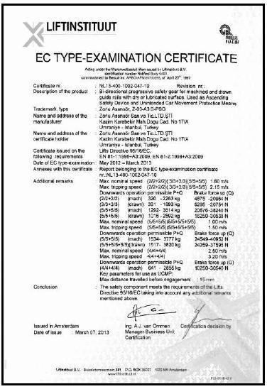
12 EC TYPE DECLARATION OF CONFORMITY Zorlu Asansör Sanayi ve Ticaret Ltd. Şti. Kazım Karabekir Mahallesi Doğu Caddesi 17/A Ümraniye - İstanbul - Turkey Phone: (0216) (Pbx) Fax :(0216) We guarantee that the following Type: Z-03+A3 B-PSG, Bi-directional Progressive Safety Gear of which name and code number is given below is in compliance with TSEN 81-1+A3 Standard Certificate No.: NL Certificate Duration : May March 2013 Date of Manufacture: Product Serial Number: ZORLU ASANSÖR SANAYİİ VE TİCARET LTD. ŞTİ. Kazım Karabekir Mahallesi Doğu Caddesi No. 17/A Ümraniye /İSTANBUL Phone: (0216) (Pbx) Fax: (0216) web: info@zorluasansor.com
Z-07+A3 BI-DIRECTIONAL PROGRESIVE SAFETY GEAR
 Z-07+A3 BI-DIRECTIONAL PROGRESIVE SAFETY GEAR COMPLIANT WITH EN-81-1+A3 STANDARD INSTALLATION, OPERATION, REPAIR & MAINTENANCE INSTRUCTIONS MANUAL 1 CONTENTS I II III IV - GENERAL DESCRIPTION OF THE PRODUCT
DYNATECH PROGRESSIVE SAFETY GEAR PR-2500-UD (V.50)
") DYNATECH PROGRESSIVE SAFETY GEAR PR-2500-UD (V.50) INSTRUCTIONS FOR USE AND MAINTENANCE - 1 - - 2 - - 3 - - 4 - - 5 - - 6 - INSTRUCTIONS FOR USE AND MAINTENANCE 1. GENERAL INDICATIONS. 2. SAFETY GEAR INSTALLATION.
DYNATECH PROGRESSIVE SAFETY GEAR PR-2500-UD (V.50) INSTRUCTIONS FOR USE AND MAINTENANCE - 1 - - 2 - - 3 - - 4 - - 5 - - 6 - INSTRUCTIONS FOR USE AND MAINTENANCE 1. GENERAL INDICATIONS. 2. SAFETY GEAR INSTALLATION.
DYNATECH PROGRESSIVE SAFETY GEAR PR-2000-UD
 Date: 20-01-2005 Check: 03 DYNATECH PROGRESSIVE SAFETY GEAR PR-2000-UD INSTRUCTIONS FOR USE AND MAINTENANCE - 1 - - 2 - - 3 - - 4 - INSTRUCTIONS FOR USE AND MAINTENANCE 1. GENERAL INDICATIONS. 2. SAFETY
DYNATECH PROGRESSIVE SAFETY GEAR PQ-3400-UD
 DYNATECH PROGRESSIVE SAFETY GEAR PQ-3400-UD INSTRUCTIONS FOR USE AND MAINTENANCE - 1 - - 2 - - 3 - - 4 - INSTRUCTIONS FOR USE AND MAINTENANCE 1. GENERAL INDICATIONS. 2. SAFETY GEAR INSTALLATION. 2.1. TO
Bi-Directional Progressive Safety Gear
 Bi-Directional Progressive Safety Gear (PRO 2000-A, PRO 2000-B, PRO 5000) Installation and Operation Instructions PRO 2000-A PRO 2000-B PRO5000 PRODUCT PRO2000-A PRO2000-B PRO5000 Speed, P+Q, [m/s] [kg]
OPERATING INSTRUCTIONS. ASTRO HOIST Type E89-CTO
 OPERATING INSTRUCTIONS ASTRO HOIST Type E89-CTO CONFORM TO EN 1808 - MARCH 1999 MACHINE DIRECTIVE 98/37 EC All persons operating this equipment must read and completely understand this manual. Any operation
Instruction manual and installation guide Traction sheave brake TSB TSB
 Instruction manual and installation guide Traction sheave brake TSB 2000-1 TSB 2000-2 Content Traction sheave brake Page 1. Safety 2 1.1 Explanation of symbols 2 1.2. General safety instructions 3 2. Product
A company of ThyssenKrupp Elevator. ThyssenKrupp Aufzugswerke. Operating Manual. Oil buffer
 A company of ThyssenKrupp Elevator ThyssenKrupp Aufzugswerke Operating Manual Oil buffer OPERATING MANUAL Printer s imprint All rights reserved. Copyright by: THYSSENKRUPP AUFZUGSWERKE GMBH P.O. box 23
ABACO MACHINES OPERATION MANUAL STONE/STEEL/GLASS/WOODS LIFTER (ASSGWL20) ABACO MACHINES (USA)
 ABACO MACHINES (USA)") ABACO MACHINES OPERATION MANUAL STONE/STEEL/GLASS/WOODS LIFTER (ASSGWL20) ABACO MACHINES (USA) 14508 S. Garfield Ave., Paramount, CA 90723, USA Tel : 310-532-0366 Fax : 310-532-99 Email : sales@abacomachines.com
ABACO MACHINES OPERATION MANUAL STONE/STEEL/GLASS/WOODS LIFTER (ASSGWL20) ABACO MACHINES (USA) 14508 S. Garfield Ave., Paramount, CA 90723, USA Tel : 310-532-0366 Fax : 310-532-99 Email : sales@abacomachines.com
Hand Pallet Truck NC. Operation Manual
 Hand Pallet Truck -------NC Operation Manual Operation Manual 1 Application Range This product is suitable for using in rated load of up to 5500lbs. This PL5500HD is the perfect jack for handling palletized
3. Operating instructions: Minor 200
 1. Technical specifications 3. Operating instructions: Minor 200 Copyright 2015 by Endecotts Ltd. 13 1. Setting up Technical specifications SIEVE SHAKER MODEL: Minor 200 General Information The Minor 200
Differential Rewind Shafts
 Differential Rewind Shafts More accurate tension control for light tension applications. Dynamically balanced central shaft. Suitable for cardboard and all types of plastic cores. Easier loading of cores
MY-TE. OPERATION and MAINTENANCE. Winch and Hoist. Provided by: Model AC 36B OF MAX AC VOLT AC
 Provided by: www.hoistsdirect.com Model AC 36B 6000# Double Line Lift Capacity MY-TE Winch and Hoist OPERATION and MAINTENANCE OF MAX AC 368-115 VOLT AC READ THIS BEFORE OPERATING UNIT INSTALLATION: Mount
Operating instructions for worm gear boxes
 Operating instructions for worm gear boxes DREHMO Sales and Service of EMG-Actuators Direct mounting Foot and lever ON/OFF- and Modulating duty Type MSG 25-S to MSG 8000-S MSG 12-R to MSG 2500-R English
Serial N... MX1 Chain Driven Pipe Cutting and Bevelling Machine Parts and Operating Manual
 Serial N... MX1 Chain Driven Pipe Cutting and Bevelling Machine Parts and Operating Manual Table of contents Section Description Page 1.0 General Information 2 2.0 Specification 2 2.1 General Specification
Braking System Layout
 The Braking System The energy used to accelerate or move a vehicle from rest to a certain speed is called Kinetic i (moving) energy. To slow the vehicle down, this kinetic energy must be converted or changed,
MRL CAR FRAME AND MACHINE CHASSIS INSTALLATION MANUAL
 MRL CAR FRAME AND MACHINE CHASSIS INSTALLATION MANUAL Contents i. Introduction... 3 ii. Safety Rules and Warnings... 3 iii. Shipping and Storage Suggestions... 3 1. Car Frame Installation Guide... 4 1.1.
Drum brakes According to DIN
 Drum brakes According to DIN 15 435 Drum brakes According to DIN 15 435 Industrial Brakes Thrusters Pressure Oil Pumps Couplings Hydraulic Buffers Cellular Buffers Rail Pliers Sheaves Hook Blocks Crane
back to main page Type: Butterfly valves Instructions and Operation Manual Warning! Warning! Danger for life! 1. Intended use Danger for life!
 Instructions and operation manual for butterfly valves This manual is intended to support the users of Herberholz butterfly valves type HRD/HRA, RD/RA, LDKE/LDKF for installation, operation and maintenance
Sisu S-Cam Drum Brakes
 Sisu S-Cam Drum Brakes (For hub reduction rear axles since 1992) Maintenance Manual Sisu Axles, Inc. Autotehtaantie 1 P.O. Box 189 FIN-13101 Hämeenlinna Finland Phone int + 358 204 55 2999 Fax int + 358
INSTALLATION AND MAINTENANCE OF TOP LOADING ARM
 INSTALLATION AND MAINTENANCE OF TOP LOADING ARM D TABLE OF CONTENTS 1. INTRODUCTION 04 2. SPECIFICATION OF THE REDLANDS LOADING ARM 04 3. INSTALLING THE LOADING ARM 3.1. Installation Procedures 05 4.
ABACO GLASS LIFTER (AGL38)
") ABACO MACHINES ABACO GLASS LIFTER (AGL38) ABACO MACHINES (USA) 14508 S. Garfield Ave., Paramount, CA 90723, USA Tel : 310-532-0366 Fax : 310-532-0499 Email : sales@abacomachines.com Website : www.abacomachines.com
ABACO MACHINES ABACO GLASS LIFTER (AGL38) ABACO MACHINES (USA) 14508 S. Garfield Ave., Paramount, CA 90723, USA Tel : 310-532-0366 Fax : 310-532-0499 Email : sales@abacomachines.com Website : www.abacomachines.com
TILLOTSON LTD., CLASH INDUSTRIAL ESTATE, TRALEE, CO. KERRY, IRELAND PHONE: FAX:
 TILLOTSON LTD., CLASH INDUSTRIAL ESTATE, TRALEE, CO. KERRY, IRELAND PHONE: +353 66 7121911 FAX: +353 66 7124503 e-mail: sales@tillotson.ie SERIES SERVICE MANUAL INTRODUCTION The gasoline engine industry
ACTUATOR HON
 ACTUATOR HON 672 672.20 OPERATING AND MAINTENANCE INSTRUCTIONS/ SPARE PARTS EDITION 01/2017 Serving the Gas Industry Worldwide Contents Page 1. General information 3 1.1 Safety information 3 2. Specific
FRP Ball Valves INSTALLATION & MAINTENANCE MANUAL
 FRP Ball Valves INSTALLATION & MAINTENANCE MANUAL FRP BALL VALVES TABLE OF CONTENTS MAINTENANCE AND INSTALLATION INSTRUCTIONS 1. 2. 2.1 2.2 2.3 2.4 GENERAL...Page 1 HANDLING...1 Receiving and Storing...1
TILLOTSON LTD., CLASH INDUSTRIAL ESTATE, TRALEE, CO. KERRY, IRELAND PHONE: FAX:
 TILLOTSON LTD., CLASH INDUSTRIAL ESTATE, TRALEE, CO. KERRY, IRELAND PHONE: +353 66 7121911 FAX: +353 66 7124503 e-mail: sales@tillotson.ie HU SERIES SERVICE MANUAL INTRODUCTION To keep apace of new market
COME.UP DV-15. Instruction manual.
 COME.UP DV-15 Instruction manual www.bigfoottrade.kz Automotive Winch Thank you for purchasing a Winch. This manual covers operation and maintenance of the winch. All information in this publication is
Electronic Testing Category 5
 Electronic Testing Category 5 Kevin Heling, March 13, 2018 WE START HERE: Rope load measuring sensors (Henning Mobile Weight Watcher System): foundation of the Alternative Testing Method (electronic testing)
Hydraulic Impact Wrench Type
 M a s c h i n e n f a b r i k G m b H Hydraulic Impact Wrench Type 6 1520 0010 Illustration can differ from the original Operation and Maintenance Manual 615200010_en_Version_03 Page 1 of 19 TECHNICAL
TILLOTSON LTD., CLASH INDUSTRIAL ESTATE, TRALEE, CO. KERRY, IRELAND PHONE: FAX:
 TILLOTSON LTD., CLASH INDUSTRIAL ESTATE, TRALEE, CO. KERRY, IRELAND PHONE: +353 66 7121911 FAX: +353 66 7124503 e-mail: sales@tillotson.ie HS SERIES SERVICE MANUAL INTRODUCTION The demand for a miniature
Type 3761 Pneumatic or Electropneumatic Positioner for Rotary Actuators. Fig. 1 Type 3761 Positioner. Mounting and Operating Instructions EB 8386 EN
 Type 3761 Pneumatic or Electropneumatic Positioner for Rotary Actuators Fig. 1 Type 3761 Positioner Mounting and Operating Instructions EB 8386 EN Edition July 2007 Contents Contents Page 1 Design and
Tension and Compression Load Cell Model 8435
 Technical Product Information w Tension and Compression Load Cell 1. Introduction... 2 2. Preparing for use... 2 2.1 Unpacking... 2 2.2 Using the instrument for the first time... 2 2.3 Grounding and potential
USER MANUAL AND SPARE PARTS LIST RINK. Model SP950. Serial Number: 1703 English
 USER MANUAL AND SPARE PARTS LIST RINK Model SP950 Serial Number: 1703 English 933.095.410 TABLE OF CONTENTS Content Page Safety Regulations... 3 Short Description... 5 Technical Features... 5 First Startup...
SECTION ZF FRONT AXLE
 04-101.01/ 1 2011JA14 SECTION 04-101.01 6 3 5 1 2 9 1. Upper radius rod 2. Lower radius rod 3. Caliper 4. BRAKE Disk 5. Pneumatic connector 6. Hub 7. steering knuckle 8. Grease Fitting 9. Pneumatic connector
Ratchet lever hoists. Ratchet lever hoists for lifting, pulling, lashing and tensioning
 4 lever hoists Ratchet for lifting, pulling, lashing and tensioning Yale Hand Lever Hoists are versatile, portable units for pulling, tensioning, lashing and lifting of loads. The operation of the Hand
ISO 8855 INTERNATIONAL STANDARD. Road vehicles Vehicle dynamics and road-holding ability Vocabulary
 INTERNATIONAL STANDARD ISO 8855 Second edition 2011-12-15 Road vehicles Vehicle dynamics and road-holding ability Vocabulary Véhicules routiers Dynamique des véhicules et tenue de route Vocabulaire Reference
I. Safety Requirement WARNING. ATV/UTV Winch
 1 2 ATV/UTV Winch Thank you for purchasing a COMEUP Winch. This manual covers operation and maintenance of the winch. All information in this publication is based on the latest production information available
Installation, Operation and Maintenance Guide II NIBCO High Performance Butterfly Valves Series 6822 and 7822
 Installation, Operation and Maintenance Guide II NIBCO High Performance Butterfly Valves Series 6822 and 7822 Statements: NIBCO High Performance Butterfly Valves, Series 6822 and 7822, have been designed
Infant Restraint Systems
 TEST METHOD 213.1 Infant Restraint Systems Revised: Issued: May 2012R April 1, 1982 (Ce document est aussi disponible en français) Table of Contents 1. Introduction... 1 2. Test Devices to be Used... 1
OPERATIONS MANUAL LEVER CHAIN HOIST
 OPERATIONS MANUAL LEVER CHAIN HOIST IMPORTANT SAFETY INFORMATION Please read, understand and follow all safety information contained in these instructions prior to the use of this hoist. Retain these instructions
Drive Unit e-drive1. Installation instructions 04/2014. English translation of the original German installation instructions
 Drive Unit e-drive1 Installation instructions 04/2014 English translation of the original German installation instructions Contents Foreword... 3 Availability... 3 Structural features in the text... 3
Product Information Overspeed governor GB 260
 Product Information GB 260 Copyright as per DIN ISO 16016. Manufactured under licence of C. Haushahn GmbH & Co. I Subject to modification. Published by SLC Sautter Lift Components GmbH & Co. KG Borsigstrasse
Installation and Operating Instruction for Brake Caliper HW 150 HFA and HW 180 HFA E e
 Installation and Operating Instruction for Brake Caliper HW 150 HFA and HW 180 HFA E 09.736e Schaberweg 30-38 Phone +49 6172 275-0 61348 Bad Homburg Fax +49 6172 275-275 Germany www.ringspann.com info@ringspann.com
Installation Manual DELT. Platform stairlift. Web: Tel: Mobile:
 Installation Manual DELT Platform stairlift Web: www.lehner-lifttechnik.at Tel: +4372783514 Email: office@lehnerlifttechnik.at Mobile: +436641612980 Table of content OBSERVE THE FOLLOWING POINTS BEFORE
Jet Fans. Instruction Manual READ AND SAVE THESE INSTRUCTIONS WARRANTY
 Jet Fans Instruction Manual READ AND SAVE THESE INSTRUCTIONS WARRANTY All Leader Fan products are guaranteed to be free from defects of workmanship or material and to function satisfactorily when properly
E4-WM5-Y371A00 MOUNTING INSTRUCTION
 E4-WM5-Y371A00 MOUNTINGINSTRUCTION IMPORTANT! PLEASE READ ALL INSTRUCTIONS FIRST! If in doubt, please contact your local BILSTEIN dealer or our sales department before installation. When replacing other
6.0 SPECIFICATIONS CONTENTS. Calibration. According to factory procedureeeeeeeeeeeeeee Accuracy*
 6.0 SPECIFICATIONS Calibration According to factory procedureeeeeeeeeeeeeee Accuracy* ± 1% full scale (FS) or ± 1 graduation on scale Scale diameter 41 mm Temperature range 45 to 115 F (10-45 C) Air humidity
MAINTENANCE MANUAL DP-265
 MAINTENANCE MANUAL DP-265 Drive Gears Sisu Axles, Inc. Autotehtaantie 1 P.O. Box 189 FIN-13101 Hämeenlinna Finland Phone int + 358 204 55 2999 Fax int + 358 204 55 2900 DP265DG.PDF (2/2003) k Table of
LX1 Inspection Manual for Model LX1B. Table of contents 1. INSPECTION CLASSIFICATION DAILY INSPECTION FREQUENT INSPECTION...
 KTI KITO Technical Information LX1 Inspection Manual for Model LX1B LX1-1.1.1 1 / 9 Edition: C 03.06 Table of contents 1. INSPECTION CLASSIFICATION...2 2. DAILY INSPECTION...3 3. FREQUENT INSPECTION...3
BUREAU OF INDIAN STANDARDS DRAFT FOR COMMENTS ONLY. (Not to be reproduced without the permission of BIS or used as an AMENDMENT)
") Doc: ET 25(6345) BUREAU OF INDIAN STANDARDS DRAFT FOR COMMENTS ONLY (Not to be reproduced without the permission of BIS or used as an AMENDMENT) DRAFT AMENDMENT NO. 3 TO IS 14665 (Part 2 / Sec 1) : 2000
Doc: ET 25(6345) BUREAU OF INDIAN STANDARDS DRAFT FOR COMMENTS ONLY (Not to be reproduced without the permission of BIS or used as an AMENDMENT) DRAFT AMENDMENT NO. 3 TO IS 14665 (Part 2 / Sec 1) : 2000
Hoist Brake Motor. Hoist Gearbox Reeving Wire Rope Construction
 DR11 Monorail Hoist Hoist Brake Motor Hoist Gearbox Reeving Wire Rope Construction Rope Drum Trolley Brake Motor Trolley gearbox Trolley Trolley Wheels Load Block Hoist VFD Controls Trolley VFD Controls
SAFETY SHUT-OFF VALVE HON
 SAFETY SHUT-OFF VALVE HON 711 711.20 OPERATING AND MAINTENANCE INSTRUCTIONS/ SPARE PARTS EDITION 01/2017 Serving the Gas Industry Worldwide Contents Page 1. General information 3 2. Safety information
Guide units. For toolmaking, fixture manufacturing and machine engineering
 Guide units For toolmaking, fixture manufacturing and machine engineering Guide units in compliance with DIN, ISO and STEINEL standards or according to your specifications Guide pillars Guide and pillar
CARTER DOWNDRAFT CARBURETOR Terraplane All Models. Technical Information
 CARTER DOWNDRAFT CARBURETOR 1934 Terraplane All Models Technical Information . Carter W-1 Downdraft Carburetors 1934 Terraplane Challenger, Model KS NOTE: Terraplane Models. Carburetor fitted with Anti-
DRIVE AXLE Volvo 960 DESCRIPTION & OPERATION AXLE IDENTIFICATION DRIVE AXLES Volvo Differentials & Axle Shafts
 DRIVE AXLE 1994 Volvo 960 1994 DRIVE AXLES Volvo Differentials & Axle Shafts 960 DESCRIPTION & OPERATION All 960 station wagon models use type 1041 rear axle assembly. All 960 4-door models use type 1045
Star Swivel-Arm Hoist Installation and Operating Instructions
 Star Swivel-Arm Hoist Installation and Operating Instructions Conveying & Hoisting Solutions P/L ABN 78 6 7. Purpose of Equipment Star Swivel-Arm Hoists are intended for the transport of materials. Star
HST -LS Interlocking device (Translation of Original Manual)
") Installation and Operating Manual for Components HST -LS Interlocking device (Translation of Original Manual) HST-LS Ident.-No.: 10268 HST-LS Ident.-No.: 10269 HST-LS, pictured Ident-Nr. 10269 The image
Installation and Operating Manual for Components HST -LS Interlocking device (Translation of Original Manual) HST-LS Ident.-No.: 10268 HST-LS Ident.-No.: 10269 HST-LS, pictured Ident-Nr. 10269 The image
DESCRIPTION OF OPERATION EcoSpace elevator with KCM831 control
 Owner s UM-01.26.001-USK All DRAFT KONE Montana 2011 rights Corporation KONE (-) guide reserved Elevator 2011-02-24 Corporation Project DESCRIPTION OF OPERATION EcoSpace elevator with KCM831 control All
Hours / 100 Marks Seat No.
 17412 16117 3 Hours / 100 Seat No. Instructions (1) All Questions are Compulsory. (2) Answer each next main Question on a new page. (3) Illustrate your answers with neat sketches wherever necessary. (4)
Theory of Machines. CH-1: Fundamentals and type of Mechanisms
 CH-1: Fundamentals and type of Mechanisms 1. Define kinematic link and kinematic chain. 2. Enlist the types of constrained motion. Draw a label sketch of any one. 3. Define (1) Mechanism (2) Inversion
Pneumatic Rotary Actuator DSO-P. Hydro-Pneumatic Actuator DSO-H
 Ihr flexibler Problemlöser in der Fluidtechnik Pneumatic Rotary Actuator DSO-P Hydro-Pneumatic Actuator DSO-H DRUMAG GmbH Fluidtechnik Glarnerstrasse 2 79713 Bad Säckingen Telefon: +49 (0)7761 / 5505-0
Pneumatic or Electropneumatic Positioner for Rotary Actuators Type Fig. 1 Type 3761 Positioner. Mounting and Operating Instructions EB 8386 EN
 Pneumatic or Electropneumatic Positioner for Rotary Actuators Type 3761 Fig. 1 Type 3761 Positioner Mounting and Operating Instructions EB 8386 EN Edition June 2004 Contents Contents Page 1 Design and
BoWex FLE-PA. BoWex FLE-PAC. KTR-N Sheet: Edition: EN 1 of BoWex FLE-PA / FLE-PAC Operating/Assembly instructions
 1 of 17 is a torsionally rigid flange coupling. It is able to compensate for shaft misalignment, for example caused by manufacturing inaccuracies, thermal expansion, etc. BoWex FLE-PA BoWex FLE-PAC Drawn:
SERIES 653 HAND OPERATED LEVER HOIST SERIES 653
 English Parts Diagram Please provide the following information: - Model number - Serial number - Part description and number as shown in parts list Figure 15 Series 653 Hand Operated Lever Hoist SERIES
LOR Series Trig-O-Matic Lite Overload Release Clutch
 LOR Series Trig-O-Matic Lite Overload Release Clutch P-3029-BG LOR Series Installation and Operation An Altra Industrial Motion Company Contents I. Introduction A. Operating Principle... 3 B. Torque Adjustment...
Installation, Operating and Maintenance Instructions Retractable Door / Art.-Nr.:
 Installation, Operating and Maintenance Instructions Retractable Door 06.2008 / Art.-Nr.: 1 818 024 ENGLISH CONTENTS PAGE 1 SAFETY REQUIREMENTS 3 1.1 Symbols and key words used 3 1.2 Designated use 3 1.3
OPERATING MANUAL. Black Bruin Hydraulic Rotators
 OPERATING MANUAL All information given in this manual is current and valid according to the information available at the time of publication. Sampo Hydraulics Ltd. reserves the rights to implement changes
INSTALLATION INSTRUCTIONS AMBASSADOR DRUM OVERHEAD SERIES 100 DUMBWAITER
 INSTALLATION INSTRUCTIONS AMBASSADOR DRUM OVERHEAD SERIES 100 DUMBWAITER The installation of Matot Drum Dumbwaiters should only be performed by qualified, experienced, and trained elevator installers.
Self-Recovery Winch WARNING. General Safety Precautions
 1 Self-Recovery Winch Thank you for purchasing a Winch. This manual covers operation and maintenance of the winch. All information in this publication is based on the latest production information available
Levelling valve
 Levelling valve 464 006 Application Purpose Maintenance Vehicles with conventionally controlled air-suspension. Control of a constant ride height of the chassis by charging the air-suspension while compressing
TRANSPONDER TERMINAL MANUAL. Version: July 2012
 Version: July 2012 2 1.0 PRODUCT DESCRIPTION 3 1.1 ORDER CODE 3 1.2 DESCRIPTION 3 2.0 WARNING 4 2.1 SAFETY 4 3.0 INSTALLATION 5 3.1 IMPORTANT 5 3.2 DIAGRAM 6 3.3 INSTALLATION PROCEDURE 7 4.0 CONNECTIONS
20Ja through 100Ja 9020Ja through 9070Ja Balancer Series Service Manual
 AERO-MOTIVE COMPANY A Woodhead Industries, Inc. Subsidiary 20Ja through 00Ja 9020Ja through 9070Ja Balancer Series Service Manual IMPORTANT SAFETY INSTRUCTIONS Please read this manual carefully and follow
TRACTION MRL LIFT ATLAS EU 2:1. Installation manual /39
 TRACTION MRL LIFT Installation manual 26.08.204 /39 Table of contents. ABOUT THIS DOCUMENT... 4. Document information.... 4.2 Safety warnings definition.... 4.3 Scope of supply.... 4.4 Information concerning
DSV. Operating Manual. Double Seal Butterfly Valve. Read and understand this manual prior to operating or servicing this product.
 Operating Manual DSV Double Seal Butterfly Valve Read and understand this manual prior to operating or servicing this product. www.sks-online.com UK DSV-UK2.qxp / 10.2005 Table of Contents: Page: 1.
Series Single seated top guided control valve. Preventive maintenance. Overhauling procedure. Wörth am Main SERVICE NOTE. Control Valve Division
 Series 2000 Single seated top guided control valve Subject to change without notice Fig. 1: Series 2000 valve assembly Preventive maintenance Preventive maintenance consists of making a periodic visual
Owner s Manual for the Travelite Electric Wheelchair
 Tel: 083 284 2973 Fax:086 232 5223 Email:ruan@cheapest-wheelchairs.co.za OR rosslyn@adpwheelchairs.co.za Web: www.cheapest-wheelchairs.co.za ORwww.adpwheelchairs.co.za Owner s Manual for the Travelite
A Assembly Instructions Space Capsule, Art-No
 A Assembly Instructions Space Capsule, Art-No. 20.01.020 T:\PLAY\Play Installation Instructions\Installation Instructions 2012-2013\20_01_020-01-en-003.doc - 1 - Revision history Revision 0 2004-06-22
TECHNICAL DOCUMENTATION
 Read before first use! VES-CL-1000 Elevator Hydraulically Operated Part No. 611000-Y-H Blohm + Voss Oil Tools Hermann-Blohm-Straße 2 20457 Hamburg Germany Telephone ++49 (0)40/3119-1826/1162 Fax ++49 (0)40/3119-8194
110KA through 200KA & 9110KA through 9150KA Balancer Series Service Manual
 AERO-MOTIVE COMPANY A Woodhead Industries, Inc. Subsidiary 0KA through 200KA & 90KA through 950KA Balancer Series Service Manual IMPORTANT SAFETY INSTRUCTIONS Please read this manual carefully and follow
Translation of the Original operating instructions Lifting device Z 70 /...
 Translation of the Original operating instructions Lifting device Z 70 /... Content 1. Lifting device / Correct use according to regulations 2. Basic principles 3. General information 4. Special remarks
RS NO: SUBJECT:
 RS-340 Thru 520 NO: SUBJECT: Springing: Frame Hangers, Load Cushions and Saddle Assembly EFFECTIVE DATE: July 1993 REVISION: E CONTENTS Item Subject Page 1 Introduction 2 2 Important Safety Notice 2 3
IMPORTANT! PLEASE READ ALL INSTRUCTIONS FIRST!
 MOUNTNG NSTRUCTON MPORTANT! PLEASE READ ALL NSTRUCTONS FRST! f in doubt, please contact your local BLSTEN dealer or our sales department before installation. When replacing other brands, BLSTEN shock absorbers
Energy Supply Systems
 Energy Supply Systems SINGLE POLE INSULATED CONDUCTOR RAIL 815 100 amps KAT0815-0001b-E Conductor rail system in a high bay storage Slip ring with conductor rail system in a stretch-foil packing machine
Color Logo use on white background only. Red: Blue: PMS Black Logo use on white background only
 Color Logo use on white background only Red: 0-0-0-0 Blue: PMS 29 0-6-0-0 Owners Manual LH400 (Lift Hoist 400) Platform Hoist This Hoist is Equipped with a Quick Change Cable Drum Effective: /18/2011 Black
Blohm+Voss Pipe Handling Equipment Special Link Connector Technical Documentation Original instructions
 Blohm+Voss Pipe Handling Equipment Special Link Connector Technical Documentation Original instructions Manual PN 554106-D Rev. 002, May 2012 Blohm + Voss Oil Tools 1 GENERAL INFORMATION Warnings and Note
OPERATING MANUAL. Black Bruin hydraulic motors S-series model D
 S-series model D CONTENTS 1 GENERAL INSTRUCTIONS... 3 1.1 About the manual... 3 1.2 Revision comments... 3 1.3 Applicability... 3 1.4 Warranty... 3 1.5 Product identification... 3 2 INSTALLATION INSTRUCTIONS...
Mounting Tools 2 Checking Clearances 3 Components 4-5 Mounting 6-21 Correct Method of Tensioning the Chain 22 Adjusting The Overall Dimension 23-24
 Mounting Tools 2 Checking Clearances 3 Components 4-5 Mounting 6-21 Correct Method of Tensioning the Chain 22 Adjusting The Overall Dimension 23-24 Maintenance 25 Repairing Main Body Patterns 26 Removal
Layher Ladders Instructions for Assembly and Use. Quality management certified according to DIN EN ISO 9001:2000 by TÜV-CERT.
 Layher Ladders Instructions for Assembly and Use Quality management certified according to DIN EN ISO 9001:2000 by TÜV-CERT Ladders CONTENTS 1. INTRODUCTION................................. 3 2. GENERAL.......................................
KEYSTONE SERIES GRF RESILIENT SEATED BUTTERFLY VALVES INSTALLATION AND OPERATION MANUAL
 Before installation these instructions must be fully read and understood Intended valve use The valve is intended to be used only in applications within the pressure/temperature limits indicated in the
NEW EQUIPMENT WARRANTY
 NEW EQUIPMENT WARRANTY We warrant that this equipment from U.S. Stoneware Corporation is within stated specifications and is free from defects in materials and workmanship. Our obligation under this warranty
SuperTrac. Axle. Service & Maintenance. Manual
 SuperTrac Axle Service & Maintenance Manual Table of Contents Page Exploded Views Section 1: General Information General Warnings Description of Axle Models Identifications Section 2: Installation Axle
Power Transmission. Installation and Operating Instructions for Brake Caliper DV / DH 020 FKM. E e.
 Power Transmission Installation and Operating Instructions for Brake Caliper DV / DH 020 FKM Schaberweg 30-34 Telephone +49 6172 275-0 61348 Bad Homburg Telefax +49 6172 275-275 Germany www.ringspann.com
Progressive Safety Gear USG-25P
 ID Unique PM.7.000342.EN Progressive Safety Gear *D729MGB$111* Blatt/sheet D729MGB.000 Stand/version F-05.04.2016 Progressive Safety Gear D729MGB 10.2014 Original Instruction www.wittur.com Product manufacturer
Rotary-Linear Actuator HSE4 Hydraulic / 100 Bar
 Rotary-Linear Actuator HSE4 Hydraulic / 100 Bar 4 Function and features K A1 G1 B1 G2 KM Y B2 RE A2 Z S2 A S1 W B KS [ Operation ] [ Operating pressure ] The Eckart rotary-linear actuator HSE4 is a combination
Northern Sales & Distribution Centre
 User Manual Industrial Door Northern Sales & Distribution Centre The Door Centre, Discovery Park, Crossley Road, Stockport, SK4 5BW /indupart /indupart /indupart /company/indupart-ltd Foreword This user
FUNCTION OF A BEARING
 Bearing FUNCTION OF A BEARING The main function of a rotating shaft is to transmit power from one end of the line to the other. It needs a good support to ensure stability and frictionless rotation. The
Lineman s Hoist. Operating, Maintenance & Parts Manual. Follow all instructions and warnings for LMST680-2
 Lineman s Hoist LMST0- Operating, Maintenance & Parts Manual Lineman s Hoist Follow all instructions and warnings for inspecting, maintaining and operating this hoist. The use of any hoist presents some
Recommended BFV Installation, Maintenance & Repair Procedures Ultraflo 300 & 400 Series Valves
 I. Introduction Recommended BFV Installation, Maintenance & Repair Procedures Ultraflo 300 & 400 Series Valves A. Butterfly Valve Seat / Disc Function The seat in most resilient-seated butterfly valves
Installation and Operating Instructions for ROBA -ES couplings Type 940. _. _ Sizes 14-48
 Table of contents: Please read and observe this Operating Instruction carefully. A possible malfunction or failure of the clutch and damage may be caused by not observing it. Page 1: - Table of contents
WAP disc brake technology. Assembly, operating and maintenance instructions
 WAP disc brake technology Assembly, operating and maintenance instructions Number MA-025 Date 22.07.2010 1 Please read this operating and service manual before starting the vehicle. It forms part of the