Mounting Tools 2 Checking Clearances 3 Components 4-5 Mounting 6-21 Correct Method of Tensioning the Chain 22 Adjusting The Overall Dimension 23-24
|
|
|
- Bruce Burns
- 6 years ago
- Views:
Transcription


1
2 Mounting Tools 2 Checking Clearances 3 Components 4-5 Mounting 6-21 Correct Method of Tensioning the Chain 22 Adjusting The Overall Dimension Maintenance 25 Repairing Main Body Patterns 26 Removal 27 Spare Parts 28 Warning Against Incorrect Use Warranty 31 1


3 Mounting Chain with S Hook - Supplied Mounting Hook - Supplied Cable Come-Along -Supplied *Hammer - Not Supplied 2
4 Tire Protection Chain is suitable for Dimension of Tires listed on the crate. Check air pressure in tire. Check the distance between tire and undercarriage see chart below (Figure A1) for minimum clearance. If the minimum clearances are not met, alteration to the vehicle may be needed. Use of smaller or worn but still usable tires may be needed. Alteration or exchange of tire protection chain to smaller material size. F Tire Protection M (mm) F (mm) Figure A1 M Figure A2 3


5 Figure A3 4 7 For tire protection chains with a tapered inner bracing, the rings and links are thinner in the tapered area. For this reason, spare parts of the appropriate size should be used. Pic A4 Pic A5 4
6 No. Description Repair with part Number 1 Pattern Connecting Ring A01 2 Forged Links A02 3 Side Chain Connecting Link A03 4 Side Chain A04 5 Tension Chain Ring A05 6 Connecting Ring or A06 (Mechanical Repair Ring) 7 Pin-Shackle for Inner Chain A07 8 D-Shackle A08 9 Tension Chain A09 10 Pin A10 11 Tension Chain Locking Plate A11 5
 forgings")
7 Pic 1.0 Spread out the chain with the face of the (side that will contact ground) forgings pointing downwards. The tension chain must be on the outer side of the wheel. (Pic 1.0) 6


8 Pic 1.1 The face of forgings downwards. Pic 1.2 Spread the chain out evenly width ways. Pic 1.3 Put the tensioning chain through the tensioning rings, then fasten the tensioning chain to the connecting ring with cable ties. 7
 From the end.")
 Attach the mounting chain to itself with a boomer")
9 Pic 2.0 Drive tire onto the chain. Stop at a distance of approx.. 2ft. (50cm) From the end. Put the mounting chain over the tire. (Pic 2.0) Attach the mounting chain to itself with a boomer fastener. (Pic 2.1) Pic 2.1 Boomer Fastener. 8


10 Pic 3.0 Connect the middle and sides of the TPC to the mounting chain with mounting hooks. (Pic 3.0) 9


11 Pic 3.1 Hook the middle of the TPC on the mounting chain with the mounting hooks. (Notice the rings of the TPC to which the hooks are attached) Pic 3.2 Hook the inner side ring of TPC to the mounting chain with the mounting hooks. (Notice the rings of the TPC to which the hooks are attached.) Pic 3.3 Hook the outside ring of TPC to the mounting chain with the mounting hooks. (Notice the ring of TPC to which the hooks are attached to) Pic 3.4 Attachment is complete. 10

12 Pic 4.0 Rotation Slowly drive a full turn of the wheel. The mounting chain will pull the TPC up and over the tire. 11

13 Pic 5.0 Stop when the 2 ends of TPC meet. Note: At this point in time if the chain is too long and needs to be altered, stop here and skip to page 23. (Adjusting the over-all dimensions) 12

.")

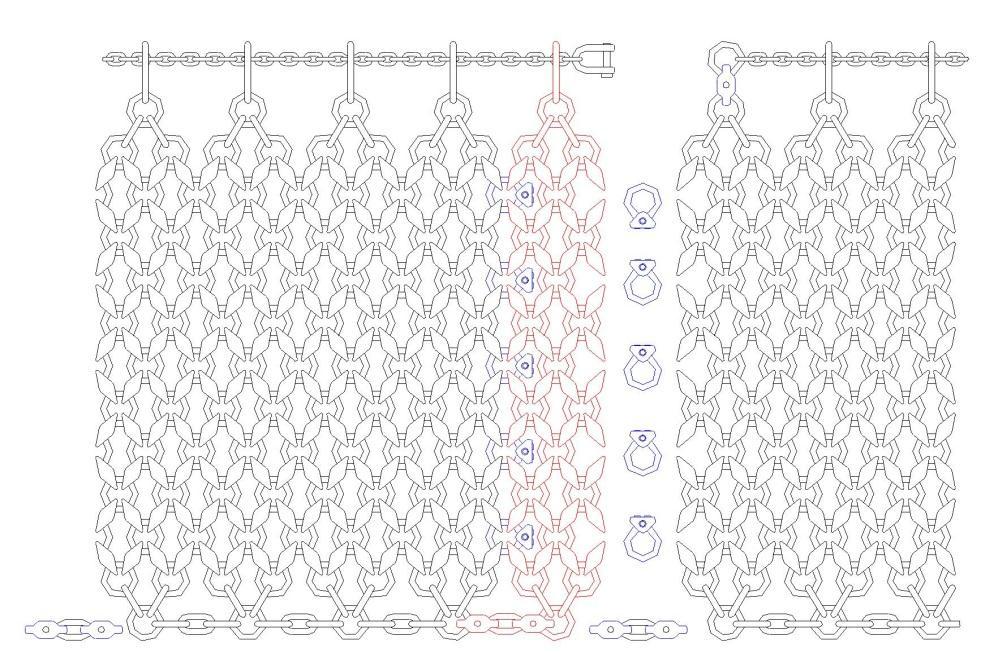
14 For in depth explanation See Step 7 Pic 6.0 Pic 6.1 Fasten the links marked red of the inner chain with the pin-shackle(part A07) and the rings marked red of the outer side chain with pin-shackle(part A07).Open the mounting chain and remove the mounting hooks. Pic 6.2 Fasten and secure all forgings marked red with connecting ring (mechanical repair ring) (part A06). Hammer pins into block. 13


15 Pic 6.3 Pic 6.4 Pic 6.5 Secure connecting ring (mechanical ring): push in the locking block, then drive in the pin. Pic 6.6 Secure pin-shackle: hook pin-shackle onto chain links or rings, then drive the pin in. 14
")


 connecting")


16 Fastening the main pattern body with connecting rings (marked in red) (mechanical repair rings ) (part A06). Pic 7.0 Pic Pass the connection ring through 2. Strike the block locking onto the the forgings.(mechanical repair rings) connecting rings. As you are installing the connecting rings (mechanical repair rings) remove the mounting hooks. 3. Fasten the second one. Pic Finish the rest. Pic 7.3 Pic 7.4 Pic Hammer the roll pin into 6. Fasten the links on the outer side the locking block to secure. chain with the pin-shackles. 15

.")
17 Pic 7.6 Pic Tighten the inner side chain with the pin-shackles by removing 1 pin and 1 link of side chain. See Pic 7.6 Attach 1 pin shackle (plug coupler) to both rings for tightened fit. See Pic 7.7 Fasten and secure all forgings with the connecting ring (part A07). Fasten the left and right chain side, Close the centre chain with pin-shackle or shackle. See Figure 7.8 Figure

 at")

18 Pic 8.0 Pic 8.1 Secure the installation tool (cable come-along) at appropriate position as shown. See Pic Pic 8.2 Pic
 then tighten the tensioning chain.")
19 Pic Drive until the pattern connection point is at the very top of the tire. Remove the mounting chain. Secure the cable style tightener at appropriate position, (see pic 8.o) then tighten the tensioning chain. Adjust the tensioning chain rings with a hammer allowing easy chain travel through the rings. 18


20 Pic Adjust the tensioning chain until the TPC chain fits snugly on the tire. To fasten the tensioning chain, push the locking plate around the tensioning chain and fasten. This is done while the installation tool is still keeping tension on the tensioning chain. See pic 10.1 Pic
 after driving backwards and forwards a number of times. Remove the installation tool if used; fasten tensioning chain end with a chain-shackle.")
21 2. Mount the locking plate to lock the tensioning chain, to avoid the tensioning chain from drawing back. 3. Remove the tightener; fasten tensioning chain ends with a chain-shackle. Repeat tensioning procedure (as in step 8-10) after driving backwards and forwards a number of times. Remove the installation tool if used; fasten tensioning chain end with a chain-shackle. See Pic 10.2 Pic


22 Pic 11.0 TPC correct fit. Drive the vehicle forward and backward in a straight line until the chain is correctly centered. That is achieved when the inner chain and tensioning chain are parallel with the rim and with an equal spacing between. (to the best of your ability) Repeat Step 8 to 10 if needed, to ensure chain is installed correctly. 21


23 Pic 12.0 Correct chain tension The chain is correctly tensioned if the forged links on the face of the tire can be slightly tilted and the tensioning chain can still be slightly pulled off the wheel by hand. On soft underground it is recommended to relieve the chain tension in order to improve grip and self-cleaning of the Chain. 22


24 1. Altering of inner chain Lengthening (a): With extension piece and two pin-shackles Shortening (b): Remove three links, fasten with one pin-shackle Figure Altering the whole chain, if altering of the inner chain is insufficient. Lengthening: build in extension piece X with connecting rings (mechanical rings). See Pic 12.2 Shortening: remove the extension piece X by removing the connecting rings. See Pic 12.3 Do not heat the neighboring rings during oxy/acetylene, plasma, etc. cutting, as loss of hardness is possible. 23

25 X Figure 12.2 X Figure


26 Check chain fitment and tension regularly. After a certain period of operation when the chain becomes loose it is necessary to retighten by adjusting the tensioning chain- refer to: Step 8 - Step 12 25

 Figure 12.")
27 Repair the chain immediately with Quality Chain spare parts in order to not cause more damage to the chain. Original Quality Chain spare parts fully replace damaged chain parts thus maintaining chain life as well as tire protection. Replacement of worn down forgings by pin-shackle (plug coupler) Figure 12.4 Replacement of worn down TPC pattern rings with connecting rings, (mechanical repair rings) Figure
28 Choose a large open working area. The tire should be positioned to have the tension chain (locking plate) on the lower side of the tire. Open the chain-shackle on the tensioning chain. Pull the tension chain through the rings, open locking plate and loosen the chain. Open the pin-shackle on the inside and outside (drive in the pin from below), disconnect the rings. Drive out the connecting rings (mechanical repair rings) pins and remove the forgings. Drive slowly forward or backward until the chain falls from the tire. 27


 Pic")

29 . Pin-Shackle (Plug coupler) Pic Connecting ring (Mechanical) repair ring Pic 13.1 Locking plate Pic 13.2 Chain-shackle (Clevis) Pic 13.3 All tire protection chain can be repaired on site with original QCC spare parts. 28
30 Congratulations on choosing QCC- Quality Chain Canada TPC (Tire Protection Chain). You have purchased a product manufactured by us using the most modern technology. However we are obliged by legal provisions to include the following warning against incorrect use. This warning must be complied with in all conditions of use and that we accept no liability for damage that is at least partly caused by the failure to comply with this warning. The chain must only be mounted by suitably trained and competent specialists. By using the tire protection chain you acknowledge that you and the corresponding specialists employed by you will take note of and comply with this warning. In case this warning is not complied with you will renounce any claim against the manufacturer and any dealer. The failure to comply with this warning could lead to product damage as well as personal injury with serious consequences. Never use tire protection chains for any other purpose than for mounting on tires. All parts of the chain, including spare parts are case-hardened to reduce wear and must therefore not be used for towing, lifting or misused in any other way. All the points in the mounting instruction must be strictly followed. The failure to do so can lead to malfunctions and damage to the vehicle as well as to accidents. Before using the vehicle for the first time after mounting the tire protection chain check that the chain is mounted correctly. In addition, the fit and state of wear of the chain should be regularly checked, at least every 200 hours of operation. When mounting or removing the chain or carrying out any other work on it please always remember its heavy dead weight. Incorrect handling can lead to serious injuries or damage caused by the chain falling off the tire. The tire protection chain must only be tensioned with the installation tool supplied or with a (come-along) tensioning chain hoist. Any other method of tensioning, such as with the shovel of a wheel-loader or a crane could damage the TPC and involve considerable danger to the mounting staff as it would submit the tension chain to excess strain, which may cause it to break. 29
31 Before mounting the tire protection chain please check that the tires are at the correct pressure and adjust if necessary. The tire pressure must not be reduced before the mounting and then increased again as this could overstrain and damage the tire tread. The resulting strain may break individual connecting rings or forgings at a later date. After mounting please check that no part of the tire protection chain contacts the vehicle. This should be carried out with the bucket or dump box lowered and the machine with its wheels turned hard over. (Loader) Correct tensioning of the tire protection chain means that it must fit to the tire in such a way that the individual forgings in the lateral chain can be moved easily. Broken forgings or rings must be replaced immediately by spare parts. In cases where spare parts are not immediately fitted there is the risk that other neighboring forgings or connection rings may break. Please take care that the wheels do not spin as this could lead to serious damage both to the TPC chain and to the tire. This leads to considerably increased wear and voids any guarantee of the chain. Do not use the tire protection chain on one wheel only-always mount in pairs. Tire protection chains may only be reconstructed to fit other tire sizes or shortened by appropriately trained specialists in a business authorized to carry out such work. We recommend to have the repaired chain inspected and approved by an expert. if in any doubt, please contact QCC Quality Chain Canada before using the repaired chain again. Please check the tension chain at regular intervals. As soon as one link has worn down by more than 1/3 of its cross-section, the entire tension chain must be replaced. QCC-Quality Chain Canada spare parts are recommended for repairs. Call Quality Chain Canada to verify if any other manufacturer s spare parts may be used. The tire protection chain has reached the end of its operating life when several forgings or rings break as a result of wear or the forged link has reached its minimum thickness. (see wear grooves on forged link) For reasons of economy we recommend that a maximum of 5% of rings and forgings of the chain be replaced. If more than 5% of the components (rings and 30


32 forgings) have been replaced by spare parts we recommend either a general overhaul of the tire protection chain or its replacement, depending on its general condition. We guarantee the use of specially tested steel according to expert analysis, superior manufacturing, correct surface hardness and proper fit of the tire protection chain. This warranty is valid for 2000 operating hours or 6 months and covers replacement of all faulty parts free of charge(except wear, thermal or other external influences). A sufficient number of spare parts is supplied with QCC tire protection chains free of charge. Additional spare parts will have to be charged. If you have any questions, contact us at: info@qccanada.com Toll Free: Fax:
INSTALLATION AND MAINTENANCE MANUAL Rev. 12/2015 Deda Elementi. seat post. seat post
 INSTALLATION AND MAINTENANCE MANUAL Rev. 12/2015 Deda Elementi seat post UK seat post Thank you for choosing a DEDA ELEMENTI and MUD product. We at DEDA ELEMENTI develop, manufacture, and constantly test
OWNER S MANUAL Z SERIES TRACKS. Rev. 355_05
 OWNER S MANUAL Z SERIES TRACKS Rev. 355_05 LOEGERING 800-373-5441 15514 37 th Street SE 701-347-5441 Casselton, ND 58012 USA Fax: 701-347-4323 E-Mail: lmi@loegering.com Internet: www.loegering.com Loegering
OWNER S MANUAL. LOEGERING th Street SE Casselton, ND USA Fax:
 OWNER S MANUAL TRAIL BLAZERS and D SERIES TRACKS LOEGERING 800-373-5441 15514 37 th Street SE 701-347-5441 Casselton, ND 58012 USA Fax: 701-347-4323 E-Mail: lmi@loegering.com Internet: www.loegering.com
OWNER S MANUAL TRAIL BLAZERS
 OWNER S MANUAL TRAIL BLAZERS LOEGERING 800-373-5441 15514 37 th Street SE 701-347-5441 Casselton, ND 58012 USA Fax: 701-347-4323 E-Mail: lmi@loegering.com Internet: www.loegering.com Owners Manual, Track,
Fitting Instruction for EZI-GRIP Bike Rack
 Fitting Instruction for EZI-GRIP Bike Rack Congratulations on purchasing Ezi-Grip to carry your valued bicycles. We are sure you will get many years of enjoyable use from your Ezi-Grip Bike Rack. These
WARRANTY REGISTRATION AND POLICY
 WARRANTY REGISTRATION AND POLICY Buhler Manufacturing products are warranted for a period of twelve (12) months from original date of purchase, by original purchaser, to be free from defects in material
TABLE OF CONTENTS DESCRIPTION. Safety Instructions & Safety Sign Locations Operating Instructions Assembly Instructions...
 TABLE OF CONTENTS DESCRIPTION PAGE Warranty... 1 Safety Instructions & Safety Sign Locations... 2 Operating Instructions... 3 Assembly Instructions... 5 500 & 600 Snowblower Drawings... 8 500 & 600 Snowblower
Warranty Policy Omni United
 1 of 6 1/27/2017 3:14 PM omni-united.com Warranty Policy Omni United ABOUT RADAR TIRES LIMITED WARRANTY This limited warranty only applies to the original purchaser of new replacement Radar tires sold
OPERATIONS MANUAL LEVER CHAIN HOIST
 OPERATIONS MANUAL LEVER CHAIN HOIST IMPORTANT SAFETY INFORMATION Please read, understand and follow all safety information contained in these instructions prior to the use of this hoist. Retain these instructions
GLO-502/530 (RIM CLAMP TIRE CHANGER)
") GLO-502/530 (RIM CLAMP TIRE CHANGER) OPERATION MANUAL DATE INSTALLED: SERIAL # MANUFACTURING DATE: (EAGLE - GLOBAL : NHT) TABLE OF CONTENT INTRODUCTION -------------------------------------------------------------------------------2
GLO-502/530 (RIM CLAMP TIRE CHANGER) OPERATION MANUAL DATE INSTALLED: SERIAL # MANUFACTURING DATE: (EAGLE - GLOBAL : NHT) TABLE OF CONTENT INTRODUCTION -------------------------------------------------------------------------------2
Assembly and Maintenance Manual Type ASNU
 Assembly and Maintenance Manual Type ASNU Hatschekstr.36 69126 Heidelberg Germany Tel +49(0)6221 30470 Fax +49(0)6221 304731 info@stieber.de www.stieber.de Date of issue: 30.05.2018 GB Revision: 0 U:\EngUsers\!ProduktDoku\1AAA_Einbauerklaerung_Wartungsanleitung_Konformitaetserklaerung\1AAA_Wartungsanleitungen\Orginal_Worddatei\_ASNU.docx
Hydraulic Drum Transporter
 Hydraulic Drum Transporter Owner s Manual WARNING: Read carefully and understand all ASSEMBLY AND OPERATION INSTRUCTIONS before operating. Failure to follow the safety rules and other basic safety precautions
Service information. How to avoid equipment failures with preventive maintenance measures. 1. General information 08/2017
 Service information 08/2017 How to avoid equipment failures with preventive maintenance measures Product line Tower pureenergy 1.1 Definitions - Qualified, trained and authorized service technician Qualified
ASSEMBLY INSTRUCTIONS
 CONTENTS ASSEMBLY INSTRUCTIONS... 1 TO THE DEALER... 1 SAFETY... 1 UNPACKING AND CHECKING PARTS... 2 Unpacking Wooden Crate...2 Checking Parts...3 TRACTOR PREPARATION... 4 Tool Box (CAB MODEL)...4 ASSEMBLY...
BX7322 Adventurer Tow Bar Operator Manual & Installation Instructions. (5,000 lb) 2 Inch Coupler
 2 Inch Coupler") Operator Manual & Installation Instructions (5,000 lb) 2 Inch Coupler General Information DO NOT INSTALL, OPERATE OR USE THIS EQUIPMENT UNTIL THE FOLLOWING OPERATING AND SAFETY INSTRUCTIONS HAVE BEEN READ
Operator Manual & Installation Instructions (5,000 lb) 2 Inch Coupler General Information DO NOT INSTALL, OPERATE OR USE THIS EQUIPMENT UNTIL THE FOLLOWING OPERATING AND SAFETY INSTRUCTIONS HAVE BEEN READ
Instructions for Fitting, Operating and Maintenance Canopy Door RE / (St.: )
") EN Instructions for Fitting, Operating and Maintenance Canopy Door 1 818 012 RE / (St.: 12.2010) 12.2010 ENGLISH Contents 1 Safety Instructions... 3 1.1 Qualified persons... 3 1.2 Symbols and signal words
EN Instructions for Fitting, Operating and Maintenance Canopy Door 1 818 012 RE / (St.: 12.2010) 12.2010 ENGLISH Contents 1 Safety Instructions... 3 1.1 Qualified persons... 3 1.2 Symbols and signal words
Installation instructions
 Installation instructions warning: never exceed your vehicle manufacturer's recommended towing capacity BOLT-TOGETHER WEIGHT DISTRIBUTION MAINTENANCE Keep the socket-mounted ends of the spring bars and
Responsible Unit: Facilities Management
 Policy Sponsor: Assistant Vice President Approval Date: January 2010 Mobile Overhead Cranes Safe Work Instructions Responsible Unit: Revisions: Service: Trade Services Shop: Mechanical & Welding Hazards
Installation Instructions
 Equipment Required: Wrenches: 9/16, 3/4, 1-1/8 Drill Bits: 11/32 Torque Wrench capable of reading 260 ft-lbs. Installation Instructions IN DEALERS: Please give these instructions to your customer. Do Not
Maintenance manual XT modules
 Maintenance manual XT modules Copyright FlexLink 2013 The contents of this publication are the publishers and may not be reproduced (even extracts) unless permission is granted. Every care has been taken
Feb 22, 2018 '67-69 Camaro & '68-74 Nova Bumpsteer Adjustment Kit
 Feb 22, 2018 '67-69 Camaro & '68-74 Nova Bumpsteer Adjustment Kit 10552 The following instructions are intended for professional installers. Speedtech Performance assumes NO responsibility for the installation
Pet Bicycle Trailer/Jogger. Owner s Manual & Instructions
 Pet Bicycle Trailer/Jogger Owner s Manual & Instructions Congratulations on your purchase of the Pet Bicycle Trailer/Jogger. Please read through this manual and following the instructions before and during
Hydraulic Bead Breaker Kit
 Hydraulic Bead Breaker Kit Owner s Manual WARNING: Read carefully and understand all ASSEMBLY AND OPERATION INSTRUCTIONS before operating. Failure to follow the safety rules and other basic safety precautions
4, 6 Suspension System. Ford F250/350 4WD Part#: ,
 Part#: 013411, 013611 4, 6 Suspension System Ford F250/350 4WD 2005-2007 Rev. 071917 491 W. Garfield Ave., Coldwater, MI 49036. Phone: 517-279-2135 E-mail: tech-bds@sporttruckusainc.com Read And Understand
ULTRA WEIGHT DISTRIBUTING HITCH SYSTEM INSTALLATION/OPERATION INSTRUCTIONS
 ULTRA-FAB PRODUCTS, INC. 57985 St. Rd. 19 South, Elkhart, Indiana 46517 ULTRA WEIGHT DISTRIBUTING HITCH SYSTEM ULTRA WEIGHT DISTRIBUTING HITCH SYSTEM INSTALLATION/OPERATION INSTRUCTIONS ITEM # 1 EXPLODED
Owners & Installation Manual. Read Instructions - Failure to assemble cover properly will void warranty.
 Owners & Installation Manual Read Instructions - Failure to assemble cover properly will void warranty. Damaged or missing parts? Call 1-877-878-9336 Mon - Fri 8 am - 5 pm CT Parts will be shipped to you
WAP disc brake technology. Assembly, operating and maintenance instructions
 WAP disc brake technology Assembly, operating and maintenance instructions Number MA-025 Date 22.07.2010 1 Please read this operating and service manual before starting the vehicle. It forms part of the
5.5 Gas & 6 Diesel Radius Arm Suspension System. Dodge Ram WD Pickup Dodge Ram WD Pickup
 Part#: 012610 5.5 Gas & 6 Diesel Radius Arm Suspension System Dodge Ram 3500 4WD Pickup 2013-17 Dodge Ram 2500 4WD Pickup 2014-17 491 W. Garfield Ave., Coldwater, MI 49036. Phone: 517-279-2135 Web: www.bds-suspension.com.
»Product» Safety Warning
 C1351 Installation Instructions 2014 Chevy/GMC, ½ Ton, 2/4wd 3.5" Combo Kit Read and understand all instructions and warnings prior to installation of product and operation of vehicle. Zone Offroad Products
HitchHoist Assembly & Operating Instructions IMPORTANT NOTICE
 HitchHoist Assembly & Operating Instructions IMPORTANT NOTICE FAILURE TO READ AND COMPLY WITH THE INSTRUCTIONS PRINTED IN THIS MANUAL COULD RESULT IN SERIOUS INJURY! IT IS STRONGLY RECOMMENDED THAT PERSONNEL
INSTALLATION CLAMP-ON FORK MOUNTED DRIVING LIGHTS 5015
 CLAMP-ON 5015 PARTS INCLUDED 2 Driving Lights 2 Side Mount Clamps-43mm/49mm 1 Hardware Kit Including: 2 49mm Spacers 4 43mm Spacers 2 Pivot Dome Washers 2 3/8-16 Serrated Hex Nut 1 Wiring Kit for Driving
MAINTENANCE WEIGHT RATINGS WARNINGS. warning: never exceed your vehicle manufacturer's recommended towing capacity
 Installation instructions warning: never exceed your vehicle manufacturer's recommended towing capacity Round Bar WEIGHT DISTRIBUTION kit MAINTENANCE Keep the socket-mounted ends of the spring bars and
»Product» Safety Warning
 J1455, J1456 Installation Instructions 1984-2001 Jeep Cherokee XJ 4.5 Suspension Lift Read and understand all instructions and warnings prior to installation of product and operation of vehicle. Zone Offroad
Heavy-Duty Drywall Dolly Cart
 Heavy-Duty Drywall Dolly Cart Owner s Manual WARNING: Read carefully and understand all ASSEMBLY AND OPERATION INSTRUCTIONS before operating. Failure to follow the safety rules and other basic safety precautions
Auto-Locking Trailer Coupler
 Auto-Locking Trailer Coupler 7-Ton Capacity Owner s Manual WARNING: Read carefully and understand all ASSEMBLY AND OPERATION INSTRUCTIONS before operating. Failure to follow the safety rules and other
TIRE GROOVER OPERATING INSTRUCTIONS UPRIGHT GROOVER
 TIRE GROOVER OPERATING INSTRUCTIONS UPRIGHT GROOVER SG MODEL READ INSTRUCTIONS THOROUGHLY BEFORE OPERATING 3451 S. 40th Street Phoenix, AZ 85040 602.437.5020 800.223.4540 www.tssissg.com info@tsissg.com
Model 3770 WARNING. Failure to comply with the safety information in these instructions could result in serious injury or death.
 B&W Trailer Hitches 1216 Hawaii Road / PO Box 186 Humboldt, KS 66748 P:620.473.3664 See Limited Lifetime Warranty at F:620.869.9031 bwtrailerhitches.com/warranty NOTE: We recommend reading instructions
PASSENGER AND LIGHT TRUCK TIRE LIMITED WARRANTY AND ADJUSTMENT POLICY
 PASSENGER AND LIGHT TRUCK TIRE LIMITED WARRANTY AND ADJUSTMENT POLICY Includes all Applicable Information on Mileage Warranty, and Customer Satisfaction Trial In addition to the valuable Warranty information
Shur-Co. Owners & Installation Manual. READ INSTRUCTIONS - Failure to assemble cover properly will void warranty.
 Owners & Installation Manual READ INSTRUCTIONS - Failure to assemble cover properly will void warranty. Damaged or missing parts? Call 1-877-878-9336 Mon - Fri 8 am - 5 pm CT Parts will be shipped to you
Installation Instructions
 86-95 Suzuki Samurai Front Shackle (SKU# SSP-HDS1) Note: These instructions also apply to SKU# SSP-HDS3 Installation Instructions Suggested Tools: CAUTION: Safety glasses should be worn at all times when
Installation. Mid-mount Toolbar System Sand Pro /Infield Pro 3040 and 5040 Traction Units Model No Serial No and Up.
 Form No. 3356-582 Rev C Mid-mount Toolbar System Sand Pro /Infield Pro 3040 and 5040 Traction Units Model No. 08731 Serial No. 260000001 and Up Installation Instructions Important: Before installing the
INSTALLATION INSTRUCTIONS
 INSTALLATION INSTRUCTIONS For 63600 and 64040 Front Bumper and Winch Mount For Ford Super Duty Trucks As you read these instructions, you may see NOTES, CAUTIONS and WARNINGS. Each message has a specific
Mounting and Operating Instructions EB EN. Type 3271 Pneumatic Actuator. Actuator area: 1000 cm². Translation of original instructions
 Type 3271 Pneumatic Actuator Actuator area: 1000 cm² Translation of original instructions Type 3271 Pneumatic Actuator Mounting and Operating Instructions Edition April 2018 Note on these mounting and
INSTALLATION INSTRUCTIONS
 INSTALLATION INSTRUCTIONS WARNING: NEVER EXCEED YOUR VEHICLE MANUFACTURER'S RECOMMENDED TOWING CAPACITY PIN-STYLE TRUNNION BAR WEIGHT DISTRIBUTION KIT MAINTENANCE Keep the socket-mounted ends of the spring
MS2200, MS2500, and MS3000 Suspension Installation Manual ON/OFF HIGHWAY SUSPENSION SYSTEM
 MS22, MS25, and MS3 Suspension Installation Manual ON/OFF HIGHWAY SUSPENSION SYSTEM 972.547.62 8.445.736 FAX: 972.542.97 725 E. UNIVERSITY ST. McKINNEY, TEXAS 7569 www.watsonsuspensions.com Watson & Chalin
Owner s Manual Read and keep this manual. Patents World Wide
 Owner s Manual Read and keep this manual. Patents World Wide S & S Industries, Inc., Sarasota, FL, USA www.trail-gator.com Copyright 2006 All Rights Reserved The following manual is provided to assist
8 Rear Suspension System. Dodge Ram Part#:
 Part#: 012619 8 Rear Suspension System Dodge Ram 2500 2014 Rev. 070518 491 W. Garfield Ave., Coldwater, MI 49036. Phone: 517-279-2135 Web: www.bds-suspension.com. E-mail: tech-bds@ridefox.com Read And
PNEUMATIC SLIDING VALVE
 INSTALLATION, OPERATION, & #: MM-SV001 6-23-09 Rev. A Page 1 of 8 PNEUMATIC SLIDING VALVE PART NUMBERS (Including, but not inclusive) SV704MSTS, SV714MSTS, SV754MSTS, SV764MSTS, SV774MSTS, SV706MSTS, SV716MSTS,
»Product» Safety Warning
 #F2622 Installation Instructions 1997-2003 Ford F-150 4WD 6" Suspension System Read and understand all instructions and warnings prior to installation of product and operation of vehicle. Zone Offroad
»Product» Safety Warning
 J1457, J1458 Installation Instructions 1984-2001 Jeep Cherokee XJ 4.5 Suspension Lift Read and understand all instructions and warnings prior to installation of product and operation of vehicle. Zone Offroad
Drum Deheader. Owner s Manual
 Drum Deheader Owner s Manual WARNING: Read carefully and understand all ASSEMBLY AND OPERATION INSTRUCTIONS before operating. Failure to follow the safety rules and other basic safety precautions may result
Final Assembly Instructions: Bikes with Threadless Headsets
 Final Assembly Instructions: Bikes with Threadless Headsets Thank you for buying your new bicycle from L.L.Bean. Read these instructions carefully before beginning the final assembly. Prior to shipping,
Hydraulic Furniture Movers
 Hydraulic Furniture Movers Owner s Manual WARNING: Read carefully and understand all ASSEMBLY AND OPERATION INSTRUCTIONS before operating. Failure to follow the safety rules and other basic safety precautions
1000 lb. Adjustable Gantry Crane
 1000 lb. Adjustable Gantry Crane Owner s Manual WARNING: Read carefully and understand all ASSEMBLY AND OPERATION INSTRUCTIONS before operating. Failure to follow the safety rules and other basic safety
Transmission Overhaul Procedures-Bench Service
 How to Assemble the Lower Reverse Idler Gear Assembly Special Instructions In 1996 Eaton changed the reverse idler system design. In the nut design, the reverse idler bearing was lubricated through a hole
Apollo Tilt Wheelchair 18" and 20" Instruction Manual
 Apollo Tilt Wheelchair 18" and 20" Instruction Manual Table of Contents Contents Table of Contents... 2 Introduction... 3 Warning... 4 Safety Guidelines... 5 Parts of the Tilt Wheelchair... 6 Setup & Operation...
Owners & Installation Manual
 Owners & Installation Manual Read Instructions - Failure to assemble cover properly will void warranty. Damaged or missing parts? Call 1-855-427-4568 Mon - Fri 8 am - 5 pm CT Parts will be shipped to you
Owners & Installation Manual. READ INSTRUCTIONS - Failure to assemble cover properly will void warranty.
 Owners & Installation Manual READ INSTRUCTIONS - Failure to assemble cover properly will void warranty. Damaged or missing parts? Call 1-605-582-7200 Mon - Fri 8 am - 5 pm CT Parts will be shipped to you
Heavy-Duty Sawhorse. Owner s Manual
 Heavy-Duty Sawhorse Owner s Manual WARNING: Read carefully and understand all ASSEMBLY AND OPERATION INSTRUCTIONS before operating. Failure to follow the safety rules and other basic safety precautions
ABACO MACHINES OPERATION MANUAL STONE/STEEL/GLASS/WOODS LIFTER (ASSGWL20) ABACO MACHINES (USA)
 ABACO MACHINES (USA)") ABACO MACHINES OPERATION MANUAL STONE/STEEL/GLASS/WOODS LIFTER (ASSGWL20) ABACO MACHINES (USA) 14508 S. Garfield Ave., Paramount, CA 90723, USA Tel : 310-532-0366 Fax : 310-532-99 Email : sales@abacomachines.com
ABACO MACHINES OPERATION MANUAL STONE/STEEL/GLASS/WOODS LIFTER (ASSGWL20) ABACO MACHINES (USA) 14508 S. Garfield Ave., Paramount, CA 90723, USA Tel : 310-532-0366 Fax : 310-532-99 Email : sales@abacomachines.com
Instructions for Use Plain Trolley ULK Geared Trolley UHK
 Instructions for Use Plain Trolley Geared Trolley Item no. Load-carrying capacity (payload) Weight Trolley widths *special trolley widths* Device dimensions mm H / W / D Minimum curve radius mm -005 0,5
55-Gallon Drum Cradle
 55-Gallon Drum Cradle Owner s Manual WARNING: Read carefully and understand all ASSEMBLY AND OPERATION INSTRUCTIONS before operating. Failure to follow the safety rules and other basic safety precautions
Operating Manual & Safety Instructions ProTorc Hydraulic Torque Wrench Model # PTLC - Please read in full before operating ProTorc Torque Wrench -
 Operating Manual & Safety Instructions ProTorc Hydraulic Torque Wrench Model # PTLC - Please read in full before operating ProTorc Torque Wrench - ProTorc Important Safety Instructions READ ALL INSTRUCTIONS
LOADER MOUNTING KIT 5211 LOADER JOHN DEERE TRACTORS
 ASSEMBLY MANUAL 2-6976 Keep with Operators Manual LOADER MOUNTING KIT 5211 LOADER JOHN DEERE TRACTORS MODEL 2WD FWA ROPS CAB JD 6110, 6120 X X X X JD 6210, 6220 X X X X JD 610, 620 X X X X JD 610, 620
Miller Compact Manual Quick Couplers
 Miller: Issue 2 Miller Compact Manual Quick Couplers For Mini Excavators (1 to 10 tonne) and Backhoe Loaders Installation Guide and Operator s Instructions IMPORTANT Keep this manual with the machine at
MAINTENANCE WEIGHT RATINGS WARNINGS. warning: never exceed your vehicle manufacturer's recommended towing capacity
 Installation instructions warning: never exceed your vehicle manufacturer's recommended towing capacity Pin-style trunnion Bar WEIGHT DISTRIBUTION MAINTENANCE Keep the socket-mounted ends of the spring
LSC 3052 PCW LANDSCAPE CART ASSEMBLY INSTRUCTIONS
 VESTIL MANUFACTURING CORP. 2999 North Wayne Street, P.O. Box 507, Angola, IN 46703 Telephone: (260) 665 7586 or Toll Free (800) 348 0868 Fax: (260) 665 339 www.vestilmfg.com e mail: sales@vestil.com LSC
Alpha Series Front Bumper Installation Manual
 1 K Alpha Series Front Bumper Installation Manual - 2003-2009 GM 4500-5500 2 Kelderman Alpha Series Front Bumper Winch Pre-Runner Bar Not Available - Contents - Kit Numbers. (3) - Introduction. (4) - Safety...
ASSEMBLY INSTRUCTIONS
 CONTENTS ASSEMBLY INSTRUCTIONS... 1 TO THE DEALER... 1 SAFETY... 1 UNPACKING AND CHECKING PARTS... 2 Unpacking Wooden Crate...2 Checking Parts...3 TRACTOR PREPARATION... 4 ASSEMBLY... 4 Boom Assembly...4
Warnings and Precautions FAILURE TO READ, UNDERSTAND AND FOLLOW THESE INSTRUCTIONS MAY LEAD TO SERIOUS INJURY OR DEATH!
 Instruction Booklet 2006 Summit ATV Pak-Mule Single Axle 84000 Summit ATV Pak-Mule Tandem Axle 84002!! READ ME FIRST!!! Please read carefully BEFORE using you new Summit ATV Product. Congratulations! You
Lbs Kgs Ft M
 Installation Instructions for 92600 ATV Winch 3000 lb. Rated Pull SPECIFICATIONS Rated line pull: 3000 lbs. (1360kgs) single line Motor: Permanent magnetic DC 12V with 1.2 hp. /0.9kw output Gear: Differential
Assembly and Maintenance Manual Type AS
 Assembly and Maintenance Manual Type AS Hatschekstr.36 69126 Heidelberg Germany Tel +49(0)6221 30470 Fax +49(0)6221 304731 info@stieber.de www.stieber.de Date of issue: 30.05.2018 GB Revision: 0 U:\EngUsers\!ProduktDoku\1AAA_Einbauerklaerung_Wartungsanleitung_Konformitaetserklaerung\1AAA_Wartungsanleitungen\Orginal_Worddatei\_AS.docx
 DRUM BRAKE RIMS Periodic inspection of drum brake rims is necessary to determine indications of uneven or excessive wear. In general, brake rim failures other that regular wear are caused by brake linings
INSTALLATION CONSTELLATION DRIVING LIGHTS 5009
 INSTALLATION CONSTELLATION DRIVING LIGHTS 5009 PARTS INCLUDED 1 Right Driving Light with Turn Signals 1 Left Driving Light with Turn Signals 1 Installation Component Kit Including: 8 Insulated Male Spades
MAINTENANCE WEIGHT RATINGS WARNINGS. warning: never exceed your vehicle manufacturer's recommended towing capacity
 Installation instructions warning: never exceed your vehicle manufacturer's recommended towing capacity Round Bar WEIGHT DISTRIBUTION MAINTENANCE Keep the socket-mounted ends of the spring bars and the
Drive Unit e-drive1. Installation instructions 04/2014. English translation of the original German installation instructions
 Drive Unit e-drive1 Installation instructions 04/2014 English translation of the original German installation instructions Contents Foreword... 3 Availability... 3 Structural features in the text... 3
IS YOUR TYRE UNDER PRESSURE?
 MEET YOUR TYRE When have you last checked the car tyres? Your tyres are the only part of your car in contact with the road; each has a contact area or foot print equivalent in size to a gents shoe sole
Mounting and Operating Instructions EB EN. Type 3271 and Type 3277 Pneumatic Actuators. Actuator areas: 175v2, 350v2, and 750v2 cm²
 Type 3271 and Type 3277 Pneumatic Actuators Actuator areas: 175v2, 350v2, and 750v2 cm² Translation of original instructions Type 3271 (left) and Type 3277 (right) Pneumatic Actuators Mounting and Operating
Protrac /Maximizer Series Over the Tire Tracks for Skid Steer Loaders User s Guide & Installation Manual
 Congratulations! You ve just purchased a new Protrac /Maximizer over the tire track system from McLaren Industries. This User s Manual covers proper installation and maintenance of your V8 Series Protrac
User Manual of Bagibike Electric Bicycles
 User Manual of Bagibike Electric Bicycles Model: Bagibike B16. http://www.bagibike.com Page 1 FOREWORD The following operation manual is a guide to assist you. This manual is not a complete document on
INSTALLATION INSTRUCTIONS FOR 2016 TOYOTA TACOMA 4 X 4 AND PRERUNNER FRONT LIGHT BAR MOUNT PART NUMBER 20016
 INSTALLATION INSTRUCTIONS FOR 2016 TOYOTA TACOMA 4 X 4 AND PRERUNNER FRONT LIGHT BAR MOUNT PART NUMBER 20016 WARNING!!! READ AND UNDERSTAND ALL INSTRUCTIONS BEFORE PROCEEDING. MAKE SURE THAT YOU HAVE ALL
2000 lb Adjustable Gantry Crane
 2000 lb Adjustable Gantry Crane Owner s Manual WARNING: Read carefully and understand all ASSEMBLY AND OPERATION INSTRUCTIONS before operating. Failure to follow the safety rules and other basic safety
Rating when used as a weight distributing hitch with spring bars:
 May 2004 APPLICATION: INSTALLATION INSTRUCTIONS MODEL NO. 70201 Bolt Together Weight Distributing Hitch System Without Shank Rating when used as a weight distributing hitch with spring bars: Part Number
Armon Edero. User manual
 User manual Armon Edero Foreword.... 2 Symbols used 2 Intended use.... 2 About the Armon Edero... 2 Mounting options of the Edero 2 Braces. 3 How to set up the Armon Edero.. 3 How to attach the brace to
DELINTE. LIMITED TIRE WARRANTY Effective July 1, 2017 DH2 D7 D8, D8+ DS8 DH7 DX9, DX10 DX11, DV2
 DELINTE LIMITED TIRE WARRANTY Effective July 1, 2017 DH2 D7 D8, D8+ DS8 DH7 DX9, DX10 DX11, DV2 Sentury Tire USA Delinte Limited Tire Warranty This limited warranty only applies to the original purchaser
Owners & Installation Manual. Read Instructions - Failure to assemble cover properly will void warranty.
 Owners & Installation Manual Read Instructions - Failure to assemble cover properly will void warranty. Damaged or missing parts? Call 1-877-878-9336 Mon - Fri 8 am - 5 pm CT Parts will be shipped to you
Mounting and Operating Instructions
 Mounting and Operating Instructions EB 8310-6 EN Translation of original instructions Type 3271 Type 3277 Type 3271 and Type 3277 Pneumatic Actuators Actuator area: 240, 350, and 700 cm² Edition March
»Product» Safety Warning
 #C9315 Installation Instructions 2000-2005 Suburban/Tahoe/Yukon 1500 2/4wd 3" Body Lift Read and understand all instructions and warnings prior to installation of product and operation of vehicle. Zone
»Product» Safety Warning
 D2201 Installation Instructions 2012-2017 Dodge Ram 1500 4WD 2" Adventure Series Suspension System Read and understand all instructions and warnings prior to installation of product and operation of vehicle.
AgriMetalINC. SELF-PROPELLED GREENS ROLLER MODEL GR-660 OPERATOR'S MANUAL
 AgriMetalINC. SELF-PROPELLED GREENS ROLLER MODEL GR-660 OPERATOR'S MANUAL AGRIMETAL INC. SELF-PROPELLED GREENS ROLLER WARRANTY AgriMetal Incorporated (AgriMetal) warrants the new Greens Roller to be free
DELINTE. LIMITED TIRE WARRANTY Effective July 1, 2017 DH2 D7 D8, D8+ DS8 DH7 DX9 DX10 DX11,, DX12 DV2 AW 5
 DELINTE LIMITED TIRE WARRANTY Effective July 1, 2017 DH2 D7 D8, D8+ DS8 DH7 DX9 DX10 DX11,, DX12 DV2 AW 5 Sentury Tire USA Delinte Limited Tire Warranty This limited warranty only applies to the original
Air Lift. Kit Honda Prelude ( ) PERFORMANCE INSTALLATION GUIDE
 PERFORMANCE INSTALLATION GUIDE") Air Lift PERFORMANCE Kit 75532 Honda Prelude (1992-2001) Cover illustration may not depict actual kit. MN-542 (06708) ECR 6206 INSTALLATION GUIDE For maximum effectiveness and safety, please read these
Air Lift PERFORMANCE Kit 75532 Honda Prelude (1992-2001) Cover illustration may not depict actual kit. MN-542 (06708) ECR 6206 INSTALLATION GUIDE For maximum effectiveness and safety, please read these
BX4330 Acclaim Tow Bar Operator Manual & Installation Instructions
 Operator Manual & Installation Instructions (5,000 lb) 2 Inch Coupler General Information DO NOT INSTALL, OPERATE OR USE THIS EQUIPMENT UNTIL THE FOLLOWING OPERATING AND SAFETY INSTRUCTIONS HAVE BEEN READ
1000-lb Hydraulic Truck Crane
 1000-lb Hydraulic Truck Crane Owner s Manual WARNING: Read carefully and understand all ASSEMBLY AND OPERATION INSTRUCTIONS before operating. Failure to follow the safety rules and other basic safety precautions
Installation Instructions READ THOROUGHLY BEFORE BEGINNING Signature Series Rail Kit Dodge Ram Trucks-all, including Mega-cabs
 INDEX Failure to follow all of these instructions may result in death or serious injury!. GUIDELINES FOR MATCHING TOW VEHICLE AND TRAILER. Pages -. DRILLED AND BOLTED INSTALLATION FIGURE. Page 4. NO-DRILL,
EZ Hauler 2500 Training & Procedure Manual
 EZ Hauler 2500 Training & Procedure Manual Load Capacity One of the most important considerations when operating this machine is the Load Capacity of the EZ Hauler 2500 s boom. The maximum weight capacity
STÜTZVORRICHTUNG MODUL
 Montage- und Betriebsanleitung STÜTZVORRICHTUNG MODUL Installation and operating instructions Instructions de montage et d utilisation Istruzioni per il montaggio e l uso Instrucciones de montaje y funcionamiento
Read and understand all instructions and warnings prior to installation of system and operation of vehicle.
 491 W. Garfield Ave., Coldwater, MI 49036 Phone: 517-279-2135 Web/live chat: www.bds-suspension.com E-mail: tech@bds-suspension.com Part#: 121619 Product: Rear Traction Bar System Read and understand all
»Product» Safety Warning
 C9151 Installation Instructions 2014-15 Chevy/GMC 1/2 Ton 2WD & 4WD 1.5" Body Lift Read and understand all instructions and warnings prior to installation of product and operation of vehicle. Zone Offroad
Chicane Coilover Kit For '70 to '81 Camaro/Firebird
 Nov 25, 2013 Chicane Coilover Kit For '70 to '81 Camaro/Firebird 1 P a g e Installation Instructions The following instructions are intended for professional installers and are guidelines only. Speedtech