INDUSTRIE 4.0 Best Partner
|
|
|
- Caren Lucas
- 5 years ago
- Views:
Transcription
1


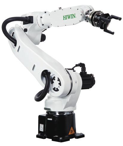


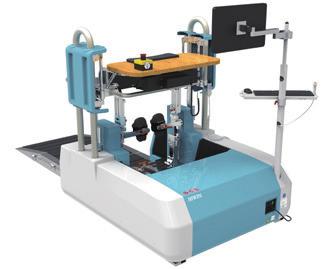

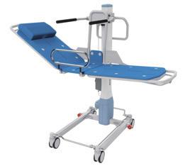


2 INDUSTRIE 4.0 Best Partner Multi Axis Robot Pick-and-place / Assembly / Array and packaging / Semiconductor / Electro-Optical industry / Automotive industry / Food industry ß Articulated Robot ß Delta Robot ß SCARA Robot ß Wafer Robot ß Electric Gripper ß Integrated Electric Gripper ß Rotary Joint Single Axis Robot Precision / Semiconductor / Medical / FPD ß KK, SK ß KS, KA ß KU, KE, KC Direct Drive Rotary Table Aerospace / Medical / Automotive industry / Machine tools / Machinery industry ß RAB Series ß RAS Series ß RCV Series ß RCH Series Ballscrew Linear Guideway Precision Ground / Rolled ß Super S series ß Super T series ß Mini Roller ß Ecological & Economical lubrication Module E2 ß Rotating Nut (R1) ß Energy-Saving & ThermalControlling (C1) ß Heavy Load Series (RD) ß Ball Spline Automation / Semiconductor / Medical ß Ball Type--HG, EG, WE, MG, CG ß Quiet Type--QH, QE, QW, QR ß Other--RG, E2, PG, SE, RC Medical Equipment Bearing Hospital / Rehabilitation centers / Nursing homes ß Robotic Gait Training System ß Hygiene System ß Robotic Endoscope Holder Machine tools / Robot ß Crossed Roller Bearings ß Ball Screw Bearings ß Linear Bearing ß Support Unit AC Servo Motor & Drive Driven Tool Holders Semiconductor / Packaging machine /SMT / Food industry / LCD ß Drives-D1, D1-N, D2T ß Motors-50W~2000W All kinds of turret ß VDI Systems Radial Series, Axial Series, MT ß BMT Systems DS, NM, GW, FO, MT, OM, MS Linear Motor Torque Motor (Direct Drive Motor) Automated transport / AOI application / Precision / Semiconductor ß Iron-core Linear Motor ß Coreless Linear Motor ß Linear Turbo Motor LMT ß Planar Servo Motor ß Air Bearing Platform ß X-Y Stage ß Gantry Systems Inspection / Testing equipment / Machine tools / Robot ß Rotary Tables-TMS,TMY,TMN ß TMRW Series ß TMRI Series
3 Warranty Terms and Conditions The period of warranty shall commence at the received date of HIWIN product (hereafter called product ) and shall cover a period of 12 months. The warranty does not cover any of the damage and failure resulting from: The damage caused by using with the production line or the peripheral equipment not constructed by HIWIN. Operating method, environment and storage specifications not specifically recommended in the product manual. The damage caused by changing installation place, changing working environment, or improper transfer after being installed by the professional installer. Product or peripheral equipment damaged due to collision or accident caused by improper operation or installation by the unauthorized staff. Installing non-genuine HIWIN products. The following conditions are not covered by the warranty: Product serial number or date of manufacture (month and year) cannot be verified. Using non-genuine HIWIN products. Adding or removing any components into/out the product without authorized. Any modification of the wiring and the cable of the product. Any modification of the appearance of the product; removal of the components inside the product. e.g., remove the outer cover, product drilling or cutting. Damage caused by any natural disaster. i.e., fire, earthquake, tsunami, lightning, windstorms and floods, tornado, typhoon, hurricane etc. HIWIN does not provide any warranty or compensation to all the damage caused by above-mentioned circumstances unless the user can prove that the product is defective. For more information towards warranty terms and conditions, please contact the technician or the dealer who you purchased with. Improper modification or disassemble the robot might reduce the robot function, stability or life. The end-effector or the cable for devices should be installed
4 and designed by a professional staff to avoid damaging the robot and robot malfunction. Please contact the technician for special modification coming from production line set up. For the safety reason, any modification for HIWIN product is strictly prohibited. 1. Safety Information Safety Responsibility and Effect Safety Precautions This chapter explains how to use the robot safely. Be sure to read this chapter carefully before using the robot. The user of the HIWIN industrial robot has responsibility to design and install the safety device meeting the industrial safety regulations in order to ensure personal safety. 2. Description Related to Safety I. Safety Symbols Carefully read the instructions in the user manual prior to robot use. The following shows the safety symbols used in this user manual. Symbol Description Failure to follow instructions with this symbol may result in serious hazard or personal injury. Please be sure to comply with these instructions. Failure to follow instructions with this symbol may result in personal injury or product damage. Please be sure to comply with these instructions. Failure to follow instructions with this symbol may result in poor product performance. Please be sure to comply with these instructions. II. Working Person The personnel can be classified as follows Operator:
5 Turns robot controller ON/OFF Starts robot program from operator s panel Reset system alarm Programmer or teaching operator: Operates the robot Teaches robot inside the safety fence Maintenance engineer: Operates the robot Teaches robot inside the safety fence Does maintenance, adjustment, replacement Programmer and the maintenance engineer must be trained for proper robot operation. 3. Warning 3.1 Common Safety Issues All operating procedures should be assessed by professional and in compliance with related industrial safety regulations. When operating robot, operator needs to wear safety equipment, such as smock for working environment, safety shoes and helmets. When encountering danger or other emergency or abnormal situation, please press the emergency stop button immediately and move the arm away with low speed in manual mode. When considering safety of the robot, the robot and the system must be considered at the same time. Be sure to install safety fence or other safety equipment and the operator must stand outside the safety fence while operating the robot. A safety zone should be established around the robot with an appropriate safety device to stop the unauthorized personnel from access. While installing or removing mechanical components, be aware of a falling piece which may cause injury to operator.
6 Ensure the weight of workpiece does not exceed the rated load or the tolerable torque. Exceeding these values could lead to the driver alarm or malfunction of the robot. Do not climb on robot. The personnel installing robot should be trained and licensed. To ensure personal safety, robot installation must comply with this manual and related industrial safety regulations. The control cabinet should not be placed near high voltage or machines that generate electromagnetic fields to prevent interference that could cause the robot to deviation or malfunction. Using non-hiwin repair components may cause robot damage or malfunction. Beware of the heat generated by the controller and servo motor. Do not overbend the cable to avoid poor circuit contact. 3.2 Operation Programming should be done outside of the safety fence. If it is inevitable to enter the safety fence, be prepared to press the emergency stop button whenever necessary. Operation should be restricted at low speed and beware of surrounding safety. 3.3 Maintenance Please contact us if the procedure not specified by HIWIN is needed. Please contact us if the replacement of the component not specified by HIWIN is needed. Be sure to carry out regular maintenance, otherwise it will affect the service life of the robot or other unexpected danger.
7 Prior to repair and maintenance, please turn off power supply. Maintenance and repair should be performed by a qualified operator with a complete understanding of the entire system to avoid risk of robot damage and personal injury. When replacing the components, avoid foreign material going into the robot. 3.4 End Effector More attention must be paid to the design of the end effector to prevent power loss or any other errors that could lead to workpiece falling or damage. The tool-type end effector is usually equipped with high voltage, high temperature and active rotary shaft. Special attention should be paid to the operating safety. The end effector should be mounted firmly on the robot to avoid workpiece release during operation which may cause personal injury or hazard. The end effector may be equipped with its own control unit. Be sure the control unit does not interfere with robot operation. 3.5 Pneumatic, Hydraulic System When using the pneumatic or hydraulic system, the gripped workpiece may fall due to insufficient pressure or gravity. 3.6 Emergency Stop The robot or other control component should have at least one device for immediate halt of n function, such as an emergency stop switch. The emergency stop button must be installed in an easily accessible location for quick stop. While executing an emergency stop, power to the
8 servo motor will be cut, and all movements will be stopped. And the control system will be shut down. Emergency stop should be reset if the restoration of operating procedure is wanted. Avoid using emergency stop to replace a normal stop procedure. This could lead to unnecessary loss to robot.
9 Content 1.Transportation and Installation 1.1 Transportation 1.2 Installation 1.3 Connection with the Controller 1.4 Grounding 1.5 Operating Ambient Conditions 1.6 Standard and Optional Equipment List 2.Basic Specifications 2.1 Description of Serial Number 2.2 Labels 2.3 Robot Specifications 2.4 Outer Dimensions and Motion Range 2.5 Wrist Moment Conditions 3.Equipment Mounting Surface and Interface 3.1 Mounting Surface for End Effector 3.2 Pneumatic Interface 3.3 I/O Interface 4.Zero-Position 4.1 Zero Position Setting 5.Maintenance and Inspection 5.1 Periodic Inspection Items 5.2 Repair Backup Batteries Replacement Timing Belt Replacement Grease Replenishment
10 Version Date Product Note RT GB First edition RT GB RT GB Manual specification updated RT GB
11 1. Transportation and Installation 1.1 Transportation Sling can be used to transport the robot. The transportation procedure is as follows: Step1. Move the robot into its transport posture and the angle of each joint is shown in the table of Figure 1-1. Step2. Secure the suspension plate to the robot with four M8 1.25P 12L screws as shown in Figure 1-2. Make the sling go through the suspension plate to keep the center of gravity under the hanging point shown as Figure 1-3. Please ensure the robot is in stable condition to avoid overturning. Step3. Move the robot to the desired position by using sling. Step4. Remove the suspension plate.
12 RT GB Transport posture J1 0 J2 45 J3-55 J4 0 J5-80 J6 0 RT GB Transport posture J1 0 J2 30 J3-55 J4 0 J5-65 J6 0 Figure 1-1 Transport posture Before carrying the robot, be sure to remove the end effector which changes the center of gravity. Please keep stable, slow down and avoid excessive vibration or shock during transportation. While placing the robot be sure to avoid the robot and the installation surface collision. After removing the suspension plate, please maintain it properly for re-transportation. Before operation, remove the suspension plate to avoid danger.
13 Hexagon socket cap screw M8x1.25Px12L Center of gravity Suspension plate Center of gravity Center of gravity Hexagon socket cap screw M8x1.25Px12L Suspension plate Center of gravity
14
15 1.2 Installation Figure 1-4 shows the installation dimensions of the robot. According to the dimensions, fix the robot on the installation surface with M10 screws. Figure 1-5, table 1-1 and table 1-2 show the forces and moments acting on the installation surface during operation. The strength of surface must be considered when installing the robot. Figure 1-5 Forces and moments acting on the installation surface
16 Table 1-1 RT GB Value of forces and moments acting on the installation surface Vertical moment Vertical force Horizontal moment Horizontal force Mv (Nm) Fv (N) MH (Nm) FH (N) Stop Acceleration /Deceleration Power cut stop Table 1-2 RT GB Value of forces and moments acting on the installation surface Vertical moment Vertical force Horizontal moment Horizontal force Mv (Nm) Fv (N) MH (Nm) FH (N) Stop Acceleration /Deceleration Power cut stop Ensure the installation surface is smooth plane which is recommended to be 6.3a or less for the roughness. If the installation surface is rough, the robot could produce the position shift during the operation. Ensure the position of the installation surface for the robot will not shift owing to the movement. Ensure the strength of the installation surface for the robot will not be damaged owing to the movement.


17 1.3 Connection with the Controller Figure 1-6 shows the structure drawing of the robot. Figure 1-7 shows the connection between robot, controller, teach pendant and power source. Figure 1-8and Figure 1-9 show the interface of J1 and the pin assignment of CN2 connector. Joint 4 Joint 6 Joint 5 + J4 - J3 - J6 + + J5 Joint J Joint Joint 1 J1 Figure 1-6Drawing of robot structure Power source Teach pendant Controller CN2 Figure 1-7 Robot and controller connection


18 Battery box Power/signal socket Air out socket Air in socket Figure 1-8 Interface at the rear of J1 Figure 1-9 Pin assignment of CN2 connector When connecting the cable, be sure to turn off power supply first.
19 1.4 Grounding Figure 1-10 shows the grounding connection of the robot with the screw (M5 0.8P 8L). Grounding wire Washer Screw Figure 1-10 Grounding method 1.5 Operating Ambient Conditions The robot operating ambient conditions is shown in Table 1-3. Table 1-3 Ambient conditions Ambient conditions Ambient temperature 0~45 [Note 1] Ambient relative humidity 75% R.H. or less No condensation permissible Altitude Up to 1000 m above mean sea level Vibration 0.5G or less Do not use under corrosive environment Do not use under flammable environment Environment Do not use under explosive environment Do not use under radiative environment [Note 1]: When the robot is stopped for a long period of time at the temperature near 0, the robot operation may have greater resistance in the beginning and then an overload alarm may be raised. It is recommended to warm up the robot at low speed for a few minutes.
20 1.6 Standard and Optional Equipment List Standard and optional equipment list is shown in Table 1-4. Table 1-4 Standard and optional equipment list Item HIWIN Part No. Standard RT GB Optional RT GB Optional Remark Teach pendant AH Calibration tool set 4C201EK1 Refer to section 4.1 End effector I/O connector 4CA30008 Refer to section 3.3 Connector set 4C Suspension plate set 4C201E41 Refer to section 1.1 Robot base (GB) 4C300F42 J2 belt Refer to section J2 belt X8 Refer to section J3 belt QN Refer to section J3 belt X9 Refer to section J5 J6 belt MY Refer to section J1~J4 grease (16KG) Refer to section J5~J6 grease (16KG) Refer to section Encoder battery LN Refer to section CN3 Emergency stop set 5M External input/output wiring set External input/output expansion module Cotton filter Battery 4C7013F2 4C201DY1 4C201DZ Y 462C0097

21 2. Basic Specifications 2.1 Description of Serial Number There is a serial number on the specification label of each robot. The explanation of serial number and model name are shown in Figure Labels Figure 2-1 Description of serial number The labels on the robot are shown in Table 2-1. Table 2-1 Labels description Labels Name Description Collision Keep safety distance from robot system, and prevent colliding to operator during operation. Grounding Electric shock Make sure grounding is completed, or it will cause electric shock. Pay more attention that the robot may have a risk of electric shock.


22 Transport posture Be aware of transport posture when transporting robot, please refer to section 1.1 for detailed information. Specification Robot specification and serial number. Air in Air out Grease in The connection port of air tube for air input. The connection port of air tube for air output. The hole for grease in. Grease out The hole for grease out.
23 2.3 Robot Specifications The robot specifications are shown in Table 2-2. Item Table 2-2 Robot specification Specification Model name RT GB RT GB Degrees of freedom 6 Installation Floor slope (wall mounting, ceiling mounting) [Note 1] Load capacity 5kg [Note 2] 5kg [Note 2] Maximum reach radius 710 mm 909 mm Cycle time 0.5 s [Note 3] Repeatability ±0.03 mm ±0.04 mm Motion range Maximum speed Allowable load moment at wrist Allowable load inertia at wrist J1 ±165 ±165 J2 +85 ~ ~ -125 J ~ ~ -55 J4 ±190 ±190 J5 ±115 ±115 J6 ±360 ±360 J1 360 / s 250 / s J2 288 / s 200 / s J3 420 / s 300 / s J4 444 / s 444 / s J5 450 / s 450 / s J6 720 / s 720 / s J N-m 8.40 N-m J N-m 8.40 N-m J N-m 5.56 N-m J kg kg- J kg kg- J kg kg- Weight 40 kg (Manipulator only) 45 kg (Manipulator only) Tool wiring Tool pneumatic pipes Protection rating 6 input / 4 output Two channels of tracheal connection (apply with M5 thread 4 tracheal caliber connector) IP32 Noise level Less than 75 db [Note 4]
24 [Note 1]: Compared to mounting on the ground, the performance of the robot may be different when mounting on the wall or ceiling. Please contact HIWIN if there s any demand for this application. [Note 2]: For details about load capacity, please refer to section 2.5. [Note 3]: The cycle time is the time that the robot moves forward and backward in the vertical height 25mm and the horizontal distance 300mm with 1 kg load, as shown in Figure 2-2. Figure 2-2 Cycle time trajectory [Note 4]: The noise level is measured at maximum speed and maximum load according to ISO11201.
25 2.4 Outer Dimensions and Motion Range The motion range is shown in Figure 2-3 and Figure 2-4. Figure 2-3 RT GB Motion range
26 Figure 2-4 RT GB Motion range C18UE

27 2.5 Wrist Moment Conditions The load capacity of the robot is not only limited by the weight of the load, but also limited by the center of gravity of the load. Figure 2-5 shows allowable center of gravity of the load when the robot is loaded 1~5kg. Figure 2-5 Wrist moment diagram
28 3. Equipment Mounting Surface and Interface 3.1 Mounting Surface for End Effector The mounting surface for end effector on the wrist end is shown in Figure 3-1. Figure 3-1 Mounting surface for end effector 3.2 Pneumatic Interface Pneumatic holes (AIR IN & AIR OUT) are installed on the rear of J1 as shown in Figure 3-2. The outer diameter of the air tube in the robot is 4mm and the secure holes for the nozzle are M5 0.8P. Figure 3-2 Pneumatic interface

29 3.3 I/O Interface I/O interface for end effector on J5 and the pin assignment of I/O connector are shown in Figure 3-3. Figure 3-4 to Figure 3-7 show the wiring diagram of I/O interface. A A side view Figure 3-3 Pin assignment of the I/O connector (Power output: 24V/1A) Figure3-4 Wiring diagram of input (Standard: Sinking type)
30 Figure 3-5 Wiring diagram of input (Optional: Sourcing type) Figure 3-6 Wiring diagram of output (Standard: Sinking type)
31 Figure 3-7 Wiring diagram of output (Optional: Sourcing type) Pin 1 and pin 9, which are 24V/1A, are used for signal, not for power input of end effector. The maximum output current at each pin is 100mA.
32 4. Zero-Position 4.1 Zero Position Setting The calibration tools for setting Zero-position are shown in Figure 4-1. The robot is adjusted to the minimum speed during the calibration, and aligns the pinhole with the calibration tool to set up the Zero-position. The procedure of resetting Zero-position with the calibration tools is shown below. Figure 4-1(a) 4-1(b) 4-1(c) Calibration tool (A) Calibration tool (B) Calibration tool (C) Figure 4-1 The calibration tool set J1-axis Zero-position setting Step1. Secure the calibration tool (A) on J1-axis by using positioning pin and screws. Step2. Operate J1 at low speed to align the positioning surface of J2 with the calibration tool (A). Step3. Finish calibration and remove the calibration tool (A). Step4. Clear encoder by HRSS. (Refer to page 34) Step5. Zeroposition etting of J1-axis is completed. Calibration tool(a) Hexagon socket cap screw M5x0.8Px6L (Nickel plated) Positioning surface Positioning pin Figure 4-2 Illustration of J1-axis Zero-position setting
33 J2-axis Zero-position setting Step1. Operate J2 at low speed to align the pinhole of J3 with the pinhole of J2. Step2. Insert the calibration tool (B) to the pinhole to calibrate Zero-position. Step3. Finish calibration and remove the calibration tool. Step4. Clear encoder by HRSS. (Refer to page 34) Step5. Zeroposition etting of J2-axis is completed. Calibration tool(b) Pinhole Figure 4-3 Illustration of J2-axis Zero-position setting J3-axis Zero-position setting Step1. Operate J3 at low speed to align the pinhole of J4 with the pinhole of J3. Step2. Insert the calibration tool (B) to the pinhole to calibrate Zero-position. Step3. Finish calibration and remove the calibration tool. Step4. Clear encoder by HRSS. (Refer to page 34) Step5. Zero-position setting of J3-axis is completed. Calibration tool(b) Pinhole Figure 4-4Illustration of J3-axis Zero-position setting
34 J4-axis Zero-position setting RT GB J4-axis Zero-position setting Step1. Operate J4 at low speed to align the keyway of J5 with the keyway of J4. Step2. Insert the calibration tool (C) to the keyway to calibrate Zero-position. Step3. Finish the calibration and remove the calibration tool. Step4. Clear encoder by HRSS. (Refer to page 34) Step5. Zero-position setting of J4-axis is completed. Calibration tool(c) Keyway Figure 4-5 Illustration of J4-axis Zero-position setting RT GB J4-axis Zero-position setting Step1. Operate J4 at low speed to align the keyway of J5 with the keyway of J4. Step2. Insert the calibration tool (C) to the keyway to calibrate Zero-position. Step3. Finish the calibration and remove the calibration tool. Step4. Clear encoder by HRSS. (Refer to page 34) Step5. Zero-position setting of J4-axis is completed. Calibration tool(c) Keyway
35 J5-axis Zero-position setting Step1. Operate J5 at low speed to align the pinhole of J6 with the pinhole of J5. Step2. Insert the calibration tool (B) to the keyway to calibrate Zero-position. Step3. Finish the calibration and remove the calibration tool. Step4. Clear encoder by HRSS. (Refer to page 34) Step5. Zero-position setting of J5-axis is completed. Pinhole Calibration tool(b) Figure 4-6 Illustration of J5-axis Zero-position setting J6-axis Zero-position setting Step1. Operate J6 at low speed to align the calibration mark of end effector with the mark of J6. Step2. Clear encoder by HRSS. (Refer to page 34) Step3. Zero-position setting of J5-axis is completed. Calibration mark Figure 4-7Illustration of J6 -axis Zero-position setting
 Step3.")

36 Clear encoder by HRSS Step1. Select the JOINT as the coordinate system. Step2. Move the robot to the Zero-position. (Refer to section 4.1) Step3. Click Main Menu>>Start-up>>Master>>Clear Encoder. (As shown in Figure 4-8) Step4. Double click the axis to clear encoder. (As shown in Figure 4-8) Figure 4-8 Clear encoder by HRSS
37 5. Maintenance and Inspection This chapter presents the maintenance and periodical inspection procedures to maintain the robot for a reasonable service life. It includes the cover removal and installation, inspection and replacement of the timing belt, lubrication position, the procedures for replacing the battery, and other notes. [Note 1] The operating time of the robot is defined as 3840 hours per year. When using the robot beyond this operating time, correct the maintenance frequencies shown in this chapter by calculation in proportion to the difference between the actual operating time and 3840 hours per year. 5.1 Periodic Inspection Items The daily inspection items before the robot operation are shown in Table 5-1. Table 5-1 Daily Inspection Items Inspection item Remedy Before turning power ON Are any of the robot installation screws, cover installation screws and end effector Securely tighten the screws. installation screws loose? Are all the cables securely connected? Such as the power and signal cable, grounding cable, the cable for teach pendant and the Securely connect. cable connected the robot and other equipment. Is the pneumatic system normal? Are there Drain the drainage system and replace the any air leak, drain clogging or hose damage? leaking component. Is the air source normal? After turning power ON 1. The robot installation screws might not be securely tightened to the installation surface. Securely tighten the screws. 2. If the roughness of the installation surface is uneven, modify the installation surface to the Check whether the robot moves smoothly reasonable surface roughness. without vibration and noise. 3. The base might not be sufficiently rigid. Please replace the base to make it more rigid. 4. There might be foreign material between the robot and the installation surface. Please remove it.
38 2 The repeatability is not within the tolerance. 5. Some operating positions might exceed the mechanism limit. Please reduce the load, speed or acceleration. 6. The timing belt might loosen or not be in correct position. Please replace or adjust the timing belt. (Refer to section 5.2.2) 7. If the grease of the reducer has not been changed for a long period. Please change the grease. (Refer to section 5.2.3) 8. If the bearing or the reducer has been damaged by the rolling surface or the gear tooth surface. Please contact HIWIN directly. 1. The Zero-position of the robot might be rewritten. Please set the Zero-position. (Refer to section 4.1) 2. The Zero-position data will be lost if the backup batteries is dead. Please replace the backup batteries (Refer to section 5.2.1) and set the Zero-position. (Refer to section 4.1) 3. The Robot J1 base retaining bolt might loosen. Please apply LOCTITE and tighten it to the appropriate torque. The project and time of periodic inspection refer to Table 5-2. Table 5-2 Periodic inspection items Inspection item Remedy Inspection item A (1 month / 320 hours) Check if there are any cracks and flows on 1 Clean and check each part of the robot. the robot. Inspection item B (3 months / 960 hours) Check the ventilation system of the If it is dusty, turn off the power and clean the 1 controller. ventilation system of the controller Inspection item C (6 months / 1920 hours) Adjust the tension of the timing belt. If the 1 Check whether the timing belt is normal. friction at the timing belt is severe, replace it. Refer to section Inspection item D (1year / 3840 hours)
39 Replace the backup battery. Refer to section 1 Replace the backup battery in the robot Inspection item E (3years/11520hours) 1 Change the lubrication grease of the reducer. Change the grease. Refer to section It is normal that the belt produces debris during operation, but if it happens right after cleaning the belt, it is recommended to replace the belt. Table 5-3 Inspection schedule
40 5.2 Repair Backup Batteries Replacement The absolute encoder of the motor is used to record the position of the robot. When the controller power is turned off, the position data of each -axis is preserved by the backup batteries. The batteries are installed when the robot is delivered from the factory. If the batteries are in use, the annual change of batteries is needed. The service life of the batteries depends on the operating conditions of the robot. In order to avoid the loss of position data, the batteries need to be changed by the user periodically. The procedure for replacing the batteries of the robot is shown in Figure 5-1 and described as below. Step1. Press the emergency stop button to prohibit the movement of the robot motion. Step2. Ensure the robot and controller are connected with the cables. Keep the power ON. Step3. Please remove the battery cover. the screws for battery cover are hexagon socket screws (M3 0.5P 6L) and the four batteries are 3.6V. Step4. Replace the battery one by one. If all batteries are removed in the same time, the position data will be lost. If so, please reset the robot to the Zero-position. All batteries should be changed at one time. Please prevent the old batteries are included. Step5. After replacing the battery, ensure to install the battery cover to prevent the robot being damaged by dust and grease. All batteries should be changed at one time. If the old batteries are included, the service life of the batteries may be reduced. Battery cover Rubber seal Cover screw Figure 5-1 The backup batteries replacement

41 5.2.2 Timing Belt Replacement The timing belt is used in the robot for the driver system of the J5 and J6 -axis. Although the belt tension has been adjusted before the robot delivery, the timing belt will wear depending on the working conditions. The belt tension might be lower than the standard after operating for a long time. The timing belt should be periodically checked, maintained and replaced. Timing Belt replacement period Check the timing belt about every 6 months. The timing belt must be replaced if the belt teeth is found cracked, worn to approximately half of the tooth width, or broken. When replacing the belt, the robot system origin may deviate. In this case, the position data must be rechecked if the origin is offset. Please refer to section 4.1 for Zero-point setting. Belt Tension It is very important to keep proper belt tension. The belt tooth jumping will happen if the belt tension is too loose. If the belt tension is too tight, it will cause damage to the motor or bearing. Measuring methods of the belt by using fingers or tools are shown in Figure 5-2. The sonic tension meter is used to measure the belt tension. The specifications and standard tension of belt are shown in Table 5-4. Belt width Span Sonic tension meter Figure 5-2 Belt tension measurement It is normal that the belt produces debris during operation, but if it happens right after cleaning the belt, it is recommended to replace the belt.
42 Table 5-4 The belt specifications Axis Model name Belt type Width(mm) Span(mm) Tension(N) 2 RT GB 365-5GT RT GB 375-5GT RT GB 440-5GT RT GB 635-5GT Common 285-3GT Common 285-3GT If the belt of J1 and J4 need to be replaced, please contact HIWIN.
43 Cover removal Before replacing the belt, remove the cover of J3 and J5 as shown in Figure 5-3. Figure 5-3 Cover removal diagram Inspection, maintenance and replacement of timing belt in J2-axis. Figure 5-4 shows the structure of J2-axis. Tension adjusting nut Screws for motor flange Tension adjusting screw Belt pulley Belt Belt pulley Figure 5-4 J2-axis structure diagram
44 Inspect J2-axis timing belt Step1. Ensure the power of controller is switched off. Step2. Remove the cover of J3. Step3. Check whether the timing belt is normal. Step4. If the timing belt is abnormal, refer to the following paragraph to replace the timing belt. Step5. If the belt tension is lower than the standard, refer to the following paragraph to adjust the belt tension. Adjust J2-axis timing belt Step1. Loose the two fixing screws on motor flange, so that the motor can be move. No need to remove the screws. Step2. Refer to Table 5-4, loosen or tighten the adjusting screw to adjust the tension of the belt. Step3. Tighten the two fixing screws on motor flange. Replace J2-axis timing belt Step1. Remove the two fixing screws on motor plate. Step2. Loose the adjusting screw to replace the timing belt. Step3. After replacing the belt, refer to the paragraph Adjust J2-axis timing belt above to adjust the tension of the belt. Inspection, maintenance and replacement of timing belt in J3-axis. Figure 5-5 shows the structure of J3-axis. Belt pulley Tension adjusting screw Tension adjusting nut belt Screws for motor flange Figure 5-5 J3-axis structure diagram Belt pulley

45 Inspect J3-axis timing belt Step1. Ensure the power of controller is switched off. Step2. Remove the cover of J3. Step3. Check whether the timing belt is normal. Step4. If the timing belt is abnormal, refer to the following paragraph to replace the timing belt. Step5. If the belt tension is lower than the standard, refer to the following paragraph to adjust the belt tension. Adjust J3-axis timing belt Step1. Loose the two fixing screws on motor flange, so that the motor can be move. No need to remove the screws. Step2. Refer to Table 5-4, loosen or tighten the adjusting screw to adjust the tension of the belt. Step3. Tighten the two fixing screws on motor flange. Replace J3-axis timing belt Step1. Remove the two fixing screws on motor plate. Step2. Loose the adjusting screw to replace the timing belt. Step3. After replacing the belt, refer to the paragraph Adjust J3-axis timing belt above to adjust the tension of the belt. Inspection, maintenance and replacement of timing belt in J5-axis. Figure 5-6 shows the structure of J5-axis. Belt pulley Belt Belt pulley Screws for motor flange Tension adjusting screw Figure 5-6 J5-axis structure diagram

46 Inspect J5-axis timing belt Step1. Ensure the power of controller is switched off. Step2. Remove the cover of J5. Step3. Check whether the timing belt is normal. Step4. If the timing belt is abnormal, refer to the following paragraph to replace the timing belt. Step5. If the belt tension is lower than the standard, refer to the following paragraph to adjust the belt tension. Adjust J5-axis timing belt Step1. Loose the two fixing screws on motor flange, so that the motor can be move. No need to remove the screws. Step2. Refer to Table 5-4, loosen or tighten the adjusting screw to adjust the tension of the belt. Step3. Tighten the two fixing screws on motor flange. Replace J5-axis timing belt Step1. Remove the two fixing screws on motor plate. Step2. Loose the adjusting screw to replace the timing belt. Step3. After replacing the belt, refer to the paragraph Adjust J5-axis timing belt above to adjust the tension of the belt. Inspection, maintenance and replacement of timing belt in J6-axis. Figure 5-7 shows the structure of J6-axis. Screws for motor flange Tension adjusting screw Belt pulley Belt Belt pulley Figure 5-7 J6-axis structure diagram
47 Inspect J6-axis timing belt Step1. Ensure the power of controller is switched off. Step2. Remove the cover of J5. Step3. Check whether the timing belt is normal. Step4. If the timing belt is abnormal, refer to the following paragraph to replace the timing belt. Step5. If the belt tension is lower than the standard, refer to the following paragraph to adjust the belt tension. Adjust J6-axis timing belt Step1. Loose the two fixing screws on motor flange, so that the motor can be move. No need to remove the screws. Step2. Refer to Table 5-4, loosen or tighten the adjusting screw to adjust the tension of the belt. Step3. Tighten the two fixing screws on motor flange. Replace J6-axis timing belt Step1. Remove the two fixing screws on motor plate. Step2. Loose the adjusting screw to replace the timing belt. Step3. After replacing the belt, refer to the paragraph Adjust J6-axis timing belt above to adjust the tension of the belt.
48 5.2.3 Grease Replenishment The grease inlets and the air vents are shown in Figure 5-8. Bevel gear air outlet J6-axis air outlet J5-axis air outlet J4-axis air outlet J3-axis air outlet J3-axis grease inlet J2-axis grease inlet J2-axis air outlet J1-axis grease inlet J1-axis air outlet J6-axis grease inlet Bevel gear grease inlet J5-axis grease inlet J4-axis grease inlet A side view Figure 5-8 Lubrication and air inlet/outlet positions
49 Grease specification Table 5-5 shows the specification of grease. Table 5-5 Grease specification Part Grease nipple Lubrication grease Quantity J1 reduction gear M6 SK-1A 93.3 ml J2 reduction gear M5 SK-1A 66.6 ml J3 reduction gear M5 SK-1A 33.3 ml J4 reduction gear M5 SK-1A 20 ml J5 reduction gear M5 SK ml J6 reduction gear M5 SK ml Bevel gear M5 SK ml Lubrication interval 3Year /11520Hr [Note1] If the robot is not used for 2 years, replace the grease of each axis. [Note2] The J3 cover needs to be removed for J2 grease replacement. Procedure of grease replenishment Step1. The grease inlets and the air outlets of the robot are shown in Figure 5-9. Step2. Remove the screw of the grease inlet, and install the grease nipple. Step3. Remove the screw of the air outlet. Step4. Replenish the grease from the grease inlet by the grease gun. Step5. Refer to Table 5-4 for the amount of grease. Step6. Install the screw of the air outlet. Step7. Remove the grease nipple, and install the screw of the grease inlet. Grease nipple Grease gun Grease inlet Figure 5-9 Grease replenishment
50
51
INDUSTRIE 4.0 Best Partner
 INDUSTRIE 4.0 Best Partner Multi Axis Robot Pick-and-place / Assembly / Array and packaging / Semiconductor / Electro-Optical industry / Automotive industry / Food industry ß Articulated Robot ß Delta
Articulated Robot - RA610-GB
 Articulated Robot - RA610-GB RT610-GB User Manual www.hiwin.tw INDUSTRIE 4.0 Best Partner Multi Axis Robot Pick-and-place / Assembly / Array and packaging / Semiconductor / Electro-Optical industry / Automotive
Articulated Robot -RA620
 Articulated Robot -RA620 User Manual www.hiwin.tw INDUSTRIE 4.0 Best Partner Multi Axis Robot Pick-and-place / Assembly / Array and packaging / Semiconductor / Electro-Optical industry / Automotive industry
SCARA Robot Controller
 SCARA Robot Controller User Manual www.hiwin.tw INDUSTRIE 4.0 Best Partner Multi Axis Robot Pick-and-place / Assembly / Array and packaging / Semiconductor / Electro-Optical industry / Automotive industry
Electric Rotary Joint. User Manual.
 Electric Rotary Joint User Manual www.hiwin.tw INDUSTRIE 4.0 Best Partner Multi Axis Robot Pick-and-place / Assembly / Array and packaging / Semiconductor / Electro-Optical industry / Automotive industry
Delta Robot - RD403 Series
 Delta Robot - RD403 Series User Manual www.hiwin.tw INDUSTRIE 4.0 Best Partner Multi Axis Robot Pick-and-place / Assembly / Array and packaging / Semiconductor / Electro-Optical industry / Automotive industry
Driven Tool Holders. Technical Information.
 Driven Tool Holders Technical Information www.hiwin.tw INDUSTRIE 4.0 Best Partner Multi Axis Robot Pick-and-place / Assembly / Grinding and Polishing / Semiconductor / Light Industry / Automotive industry
Linear Bearing. Technical Information.
 Linear Bearing Technical Information www.hiwin.tw INDUSTRIE 4. Best Partner Multi Axis Robot Pick-and-place / Assembly / Array and packaging / Semiconductor / Electro-Optical industry / Automotive industry
R-SERIES MULTI-AXIS INDUSTRIAL ROBOTS
 Automation Solutions R-SERIES MULTI-AXIS INDUSTRIAL ROBOTS COMPACT MULTI-AXIS INDUSTRIAL ROBOTS FOR COMPLEX PROCESSING TASKS Reduce Manufacturing Costs Improve Production Time Increase Throughput Engineering
Installation and Connection Manual
 Installation and Connection Manual E Controller Kawasaki Heavy Industries, Ltd. 90202-1204DEA Preface Preface This manual describes the installation and connection of Kawasaki Painting Robot KJ series.
SCARA ROBOT. G1 series MANIPULATOR MANUAL
 SCARA ROBOT G1 series MANIPULATOR MANUAL Rev.11 EM16XR3291F MANIPULATOR MANUAL G1 series Rev.11 SCARA ROBOT G1 series Manipulator Manual Rev.11 Copyright 2009-2016 SEIKO EPSON CORPORATION. All rights reserved.
INDUSTRIE 4.0 Best Partner
 Linear Motor Total Solution Ironcore Motors Shaft Motors - High thrust - Point-to-point motion applications - No cogging force - Lower velocity ripple - Scan motion applications Planar Motors Super S series
Motion Control and System Technology
 Articulated Robots Linear Guideway RA Series 6-Axis Robots RD Series Delta Robots - RA Series robots are a compact and agile automation solution with multiple configurations - 5kg, 10kg and 20kg weight
SCARA ROBOT. LS series MANIPULATOR MANUAL
 SCARA ROBOT LS series MANIPULATOR MANUAL Rev.11 EM179R3531F MANIPULATOR MANUAL LS series Rev.11 SCARA ROBOT LS series Manipulator Manual Rev.11 Copyright 2011-2017 SEIKO EPSON CORPORATION. All rights reserved.
Arm - TX series 40 family
 Arm - TX series 40 family Characteristics Stäubli Faverges 2005 D18327304A - 02/2005 The specifications contained in the present document can be modified without notice. Although all necessary precautions
Robots KR CYBERTECH With F and C Variants Specification
 Robots KR CYBERTECH With F and C Variants Specification Issued: 25.06.2018 Spez KR CYBERTECH V4 KUKA Deutschland GmbH Copyright 2018 KUKA Deutschland GmbH Zugspitzstraße 140 D-86165 Augsburg Germany This
SCARA ROBOT. G3 series MANIPULATOR MANUAL
 SCARA ROBOT G3 series MANIPULATOR MANUAL Rev.13 EM179R3525F MANIPULATOR MANUAL G3 series Rev.13 SCARA ROBOT G3 series Manipulator Manual Rev.13 Copyright 2008-2017 SEIKO EPSON CORPORATION. All rights reserved.
BoWex FLE-PA. BoWex FLE-PAC. KTR-N Sheet: Edition: EN 1 of BoWex FLE-PA / FLE-PAC Operating/Assembly instructions
 1 of 17 is a torsionally rigid flange coupling. It is able to compensate for shaft misalignment, for example caused by manufacturing inaccuracies, thermal expansion, etc. BoWex FLE-PA BoWex FLE-PAC Drawn:
Focus on Sci. & Tech. Grasp Details
 Focus on Sci. & Tech. Grasp Details B Series Safety brake, adopts modular design and has multiple functions, which can facilitate super rapid response with its professionally designed for low power electromagnetic
KR 30, 60-4 KS; KR 60 L16-2 KS
 Robots KUKA Deutschland GmbH KR 30, 60-4 KS; KR 60 L16-2 KS With F Variants Specification KR 30, 60-4 KS; KR 60 L16-2 KS Issued: 15.05.2018 Version: Spez KR 30, 60-4 KS V1 Copyright 2018 KUKA Deutschland
Arm - RX series 170B family
 Arm - RX series 170B family Characteristics Stäubli Faverges 2004 D18325304B - 11/2004 The specifications contained in the present document can be modified without notice. Although all necessary precautions
Cat. No. I194E-EN-03B. Washdown Delta Robot ZX-T Series. Delta Robot IP67 Mini Delta Robot IP67 INSTALLATION MANUAL
 Cat. No. I194E-EN-03B Washdown Delta Robot ZX-T Series R6Y3 Series Delta Robot IP67 Mini Delta Robot IP67 INSTALLATION MANUAL CONTENTS R6Y3 Installation Manual Safety Instructions 1. Safety Information
YAMAHA SCARA ROBOT. User s Manual ENGLISH. E22-Ver. 5.18
 YAMAHA SCARA ROBOT User s Manual ENGLISH E E22-Ver. 5.18 Before using the robot (Be sure to read the following notes.) At this time, our thanks for your purchase of this YAMAHA YK-X series SCARA robot.
Product Specification
 Product Specification IRB 6400S 3HAC 9121-1 / Rev. 1 M2000 The information in this document is subject to change without notice and should not be construed as a commitment by ABB Automation Technologies,
Toothed belt axis ELGC-TB-KF. Operating instruction [ ]
![Toothed belt axis ELGC-TB-KF. Operating instruction [ ]](/thumbs/83/87984161.jpg "Toothed belt axis ELGC-TB-KF. Operating instruction [ ]") Toothed belt axis ELGC-TB-KF en Operating instruction 8068220 2017-02 [8068222] Original instructions Identification of hazards and instructions on how to prevent them: Danger Immediate dangers which can
Toothed belt axis ELGC-TB-KF en Operating instruction 8068220 2017-02 [8068222] Original instructions Identification of hazards and instructions on how to prevent them: Danger Immediate dangers which can
SA Series Robot Instruction Manual
 SA Series Robot Instruction Manual Product Series: Full range of SA series Publication Status: Standard Revision: A-0001 ADTECH (SHENZHEN) TECHNOLOGY CO., LTD. Copyright. All Rights Reserved. Without prior
KR 30, 60-3; KR 30 L16-2
 Robots KUKA Roboter GmbH KR 30, 60-3; KR 30 L16-2 With F and C Variants Specification KR 30, 60-3; KR 30 L16-2 Issued: 24.10.2017 Version: Spez KR 30, 60-3 V1 Copyright 2017 KUKA Roboter GmbH Zugspitzstraße
Installation, Operation, and Maintenance Manual
 Industrial Process Installation, Operation, and Maintenance Manual Series PBFV Plastic Lined Butterfly Valve - Lug and Wafer Style Table of Contents Table of Contents Introduction and Safety...2 Safety
Below, you can see the warning symbols used throughout the manual and their meaning.
 FMI60201 Frameless motors INTRODUCTION FMI-series frameless motors by Rozum Robotics are designed to provide motion as part of a motion system. Available in a range of sizes (dia. 40, 50, 60, 75 mm), FMI
Handling & General Application
 MOTOMAN 13 552 333 www.ragroup.com.au GP-Series Handling & General Application Controlled by YRC1 Motoman GP-Series Robot System Solutions MOTOMAN GP-Series Find smart solutions for production site issues
Horizontal Articulated Robot IX Series
 Horizontal Articulated Robot IX Series Ceiling-mount Type, Arm Length 500/600/700/800 IX-HNN50 /60 /70 /80 IX-INN50 /60 /70 /80 Operation Manual Second Edition Introduction Thank you for purchasing an
TRANSERVO Series. Ver SS04/SS05/SS05H SR03/SR04/SR05 SRD03/SRD04/SRD05 EUD E45
 TRANSERVO Series SS04/SS05/SS05H SR03/SR04/SR05 SRD03/SRD04/SRD05 Ver. 3.00 EUD0127300 E45 General Contents Introduction Chapter 1 Using the Robot Safely 1-1 Safety information 1-1 1-2 Essential precautions
Modular. Precise. Robust. AGE-S-XYZ Compensation Unit
 Modular. Precise. Robust. AGE-S-XYZ Compensation Unit Compensation unit compensating in XY- and Z-direction. Field of Application Palletizing, joining, and assembly of workpieces Advantages Your benefit
INTRODUCTION WARNING SIGNS AND THEIR MEANINGS
 INTRODUCTION FMI-series frameless motors by Rozum Robotics are designed to provide motion as part of a motion system. Available in a range of sizes (stator dia. 41, 51, 75 mm), FMI motors are suitable
KR QUANTEC prime. Robots. With F and C Variants Specification. KUKA Roboter GmbH. Issued: Version: Spez KR QUANTEC prime V10 KR QUANTEC
 Robots KUKA Roboter GmbH KR QUANTEC prime With F and C Variants Specification KR QUANTEC prime Issued: 31.08.2016 Version: Spez KR QUANTEC prime V10 Copyright 2016 KUKA Roboter GmbH Zugspitzstraße 140
Before equipment use, please read this operation manual carefully. Serial Number: Date Purchased:
 Pushed & Geared Trolleys OPERATION MANUAL This operation manual is intended as an instruction manual for trained personnel who are in charge of installation, maintenance, repair etc. Before equipment use,
Modular. Precise. Robust. AGE-S-XYZ Compensation Unit
 AGE-S Modular. Precise. Robust. AGE-S-XYZ Compensation Unit Compensation unit compensating in XY- and Z-direction Field of Application Palletizing, joining, and assembly of workpieces Advantages Your benefit
6-Axis Robots. VT series MANIPULATOR MANUAL
 6-Axis Robots VT series MANIPULATOR MANUAL Rev.1 EM18YR3817F MANIPULATOR MANUAL VT series Rev.1 6-Axis ROBOT VT series Manipulator Manual Rev.1 Copyright 2018 SEIKO EPSON CORPORATION. All rights reserved.
Cat. No. I159E-EN-01. SCARA Robots ZX-T XG Series. R6Y - XGC/XGP series MAINTENANCE MANUAL
 Cat. No. I159E-EN-01 SCARA Robots ZX-T XG Series R6Y - XGC/XGP series MAINTENANCE MANUAL CONTENTS XGC/XGP Maintenance Manual Safety Instructions 1. Safety Information S-1 2. Signal words used in this
MECHANICAL CYLINDERS Operating Instructions
 SW3001EN.1 MECHANICAL CYLINDERS Operating Instructions Sweden Int +46 372 265 00 info@swedrive.se Vat.no SE556145631901 138-4551 1 Table of Contents 1. Health and Safety... 3 1.1. Notice about safety...
Explosion-Proof Painting Robots
 Explosion-Proof Painting Robots up to 20 kg payload Kawasaki Robotics (USA), Inc. EXPLOSION-PROOF PAINTING ROBOTS The K-Series line of painting robots combines high operational performance with powerful
BAH series Use and Maintenance Manual
 Page 1 of 15 BAH 225-280 series Use and Maintenance Manual Page 2 of 15 We would like to thank you for trusting us and buying our product. Field of application Before starting the motor, it s necessary
 heet: 1 of 22 Backlash-free, torsionally stiff and maintenance-free coupling Type with setscrew Type with clamping hubs Type KN (Taper hubs) Type M with setscrew Type M with clamping hubs Type PI 11-3379-883
YAMAHA CARTESIAN ROBOT. User s Manual ENGLISH. E25-Ver. 1.10
 YAMAHA CARTESIAN ROBOT User s Manual ENGLISH E E25-Ver. 1.10 CONTENTS CHAPTER 1 Using the Robot Safely 1 Safety Information...1-1 2 Essential Caution Items...1-2 3 Special Training for Industrial Robot
SERVO MOTORS BRUSHLESS SERVO MOTORS OPERATING INSTRUCTIONS 2016
 SERVO MOTORS BRUSHLESS SERVO MOTORS OPERATING INSTRUCTIONS 2016 3009/16 en Ed.02.2016 Read these Operating Instructions before performing any transportation, installation, commissioning, maintenance or
Installation, Operation, and Maintenance Manual
 Industrial Process Installation, Operation, and Maintenance Manual Series PBV Plastic Lined Ball Valve Table of Contents Table of Contents Introduction and Safety...2 Safety message levels...2 User health
SCARA ROBOT. LS20 series MANIPULATOR MANUAL
 SCARA ROBOT LS20 series MANIPULATOR MANUAL Rev.5 EM183R3615F MANIPULATOR MANUAL LS20 series Rev.5 SCARA ROBOT LS20 series Manipulator Manual Rev.5 Copyright 2016-2018 SEIKO EPSON CORPORATION. All rights
RS3-55 series SCARA ROBOT MANIPULATOR MANUAL
 SCARA ROBOT RS3-55 series MANIPULATOR MANUAL Rev.1 EM108R2070F This manual describes the information on how to use RS3-55 series. For other information, refer to RS series manipulator manual. MANIPULATOR
EPL160/EPL300 Manipulator Manual
 Motoman NX100 Controller EPL160/EPL300 Manipulator Manual Part Number: 150778-1CD Revision: 0 Motoman, Incorporated 805 Liberty Lane West Carrollton, OH 45449 TEL: (937) 847-6200 FAX: (937) 847-6277 24-Hour
Robots. KUKA Deutschland GmbH KR QUANTEC PA. With HO and arctic Variants Specification KR QUANTEC. Version: Spez KR QUANTEC PA V9
 Robots KUKA Deutschland GmbH KR QUANTEC PA With HO and arctic Variants Specification KR QUANTEC PA Issued: 24.05.2018 Version: Spez KR QUANTEC PA V9 Copyright 2018 KUKA Deutschland GmbH Zugspitzstraße
Package Contents Part A (3) I-Beam (1) Base (2) Other parts
 I-Beam (1) Base (2) Other parts") Page 1 Installation Instructions for 81245 Adjustable Height Gantry Crane 1-Ton Capacity Table of Contents Important Safety Information pg. 2 Specific Operation Warnings pg. 2 Main Parts of Product pg.
Page 1 Installation Instructions for 81245 Adjustable Height Gantry Crane 1-Ton Capacity Table of Contents Important Safety Information pg. 2 Specific Operation Warnings pg. 2 Main Parts of Product pg.
PNEUMATIC CLUTCH-BRAKE SERIE 58
 MOUNTING & MAINTENANCE INSTRUCTIONS PNEUMATIC CLUTCH-BRAKE SERIE 58 PLEASE READ THIS MANUAL VERY CAREFULLY BEFORE SETTING UP THE CLUTCH-BRAKE UNIT GOIZPER S. COOP. Antigua, 4 20577 Antzuola (Guipúzcoa)
Lumitester PD-20 Control Kit
 日本語による取扱説明は 17 ページからとなります Lumitester PD-20 Control Kit Operation manual Thank you for purchasing the Lumitester PD-20 Control Kit. To use this kit safely and correctly, read this operation manual carefully
DATAFLEX 42/1000 Torque Measuring Shaft Operating/Assembly instructions DATAFLEX
 DATAFLEX 4/1000 1 of 1 DATAFLEX Torque measuring shaft type 4/1000 Drawn: 017-01-0 Shg/Koe Replaced for: dated 015-04-13 Verified: 017-01-0 Shg Replaced by: DATAFLEX 4/1000 of 1 DATAFLEX is a maintenance-free
USE and MAINTENANCE INSTRUCTION MANUAL AZ3 HTE2 AZ3 HTE2 HVLP GRAVITY. SPRAY GUN Series. en it fr es pt de se
 USE and MAINTENANCE INSTRUCTION MANUAL AZ3 HTE2 AZ3 HTE2 HVLP GRAVITY SPRAY GUN Series en it fr es pt de se TECHNICAL DATA Technical AZ3 HTE2 AZ3 HTE2 HVLP 1.0 80 180 1.3 10-15HTE 140 200 240 1.5 2.0 160
6.0 SPECIFICATIONS CONTENTS. Calibration. According to factory procedureeeeeeeeeeeeeee Accuracy*
 6.0 SPECIFICATIONS Calibration According to factory procedureeeeeeeeeeeeeee Accuracy* ± 1% full scale (FS) or ± 1 graduation on scale Scale diameter 41 mm Temperature range 45 to 115 F (10-45 C) Air humidity
Linear Alignment. motion. 2 Flexible combination of XY. 4 High resolution and high responsiveness. accuracy. Optical linear encoder scale head
 SADE SADE/X SADE/S 2 2 Alignment Stage SA Linear motor drive SA DE Crossed roller bearing -table Linear Alignment Points 1Compact XY-table motion. Using a Linear Way L miniature linear motion rolling guide
SPV Series Slides OPERATING MANUAL. Table of contents 1 Introduction Compliance with the EC Directives Names of parts...
 HL-17012 SPV Series Slides OPERATING MANUAL Thank you for purchasing an Oriental Motor product. This Operating Manual describes product handling procedures. Please read this Operating Manual and the separate
Dry installed pump type LANDY BTP.
 OPERATION & MAINTENANCE MANUAL Dry installed pump type LANDY BTP. Landustrie Sneek BV Pieter Zeemanstraat 6 Tel. 0031 515-486888 P.O. BOX 199 Fax. 0031 515-412398 NL-8600 AD Sneek info@landustrie.nl The
Product Specification
 Product Specification IRB 640 3HAC 9217-1 / Rev. 1 M2000 The information in this document is subject to change without notice and should not be construed as a commitment by ABB Automation Technologies,
PowerLink GW series Eddy Current Dynamometer User Manual
 PowerLink GW series Eddy Current Dynamometer User Manual XiangYi (Hong Kong) Power Testing Instrument Co. Ltd. 0 GW Series Eddy Current Dynamometer User Manual Transport, Storage, use of environmental
BEFORE USING THE PRODUCT
 HL-17015-5 BEFORE USING THE PRODUCT Thank you for purchasing an Oriental Motor product. Please read this BEFORE USING THE PRODUCT and the separate manual entitled OPERATING MANUAL thoroughly to ensure
Assembly and Maintenance Manual Type ASNU
 Assembly and Maintenance Manual Type ASNU Hatschekstr.36 69126 Heidelberg Germany Tel +49(0)6221 30470 Fax +49(0)6221 304731 info@stieber.de www.stieber.de Date of issue: 30.05.2018 GB Revision: 0 U:\EngUsers\!ProduktDoku\1AAA_Einbauerklaerung_Wartungsanleitung_Konformitaetserklaerung\1AAA_Wartungsanleitungen\Orginal_Worddatei\_ASNU.docx
Robots. KUKA Roboter GmbH. KR QUANTEC extra HA. Specification KR QUANTEC. extra HA. Issued: Version: Spez KR QUANTEC extra HA V4
 Robots KUKA Roboter GmbH KR QUANTEC extra HA Specification KR QUANTEC extra HA Issued: 26.08.2016 Version: Spez KR QUANTEC extra HA V4 Copyright 2016 KUKA Roboter GmbH Zugspitzstraße 140 D-86165 Augsburg
Maximum Payload High Wrist Torque Robots
 Maximum Payload High Wrist Torque Robots up to 700 kg payload Kawasaki Robotics (USA), Inc. MAXIMUM PAYLOAD HIGH WRIST TORQUE ROBOTS The M-Series maximum payload robots incorporate a compact profile design
THREE PHASE AND SINGLE PHASE ASYNCHRONOUS ELECTRIC MOTORS OPERATION AND MAINTENANCE BOOKLET Rev
 MORATTO S.R.L. Electrical Machinery I 31030 PERO DI BREDA (Treviso) Italy Via A Volta, 2 Tel. +390422904032 fax +39042290363 www. moratto.it - moratto@moratto.it THREE PHASE AND SINGLE PHASE ASYNCHRONOUS
ISP-500B. Oil-free Scroll Vacuum Pump. Instruction Manual. View our inventory. Record of Pump Information. Serial Number: Purchase date:
 ISP-500B Oil-free Scroll Vacuum Pump Instruction Manual View our inventory Serial Number: Record of Pump Information Purchase date: In Service date: Dealer information: IM-500B 1/3/07 Page 1 of 26 Important
Electric cylinder ESBF-BS/-LS Operating instructions b [ ]
![Electric cylinder ESBF-BS/-LS Operating instructions b [ ]](/thumbs/81/84386573.jpg "Electric cylinder ESBF-BS/-LS Operating instructions b [ ]") Electric cylinder ESBF-BS/-LS-32... 100 en Operating instructions 8076295 2017-11b [8079297] Translation of the original instructions Symbols: Warning Installation and commissioning may only be performed
Electric cylinder ESBF-BS/-LS-32... 100 en Operating instructions 8076295 2017-11b [8079297] Translation of the original instructions Symbols: Warning Installation and commissioning may only be performed
CKR Compact Modules with Ball Rail Guides and Toothed Belt Drive. The Drive and Control Company
 CKR Compact Modules with Ball Rail Guides and Toothed Belt Drive The Drive and Control Company Bosch Rexroth Corp. Linear Motion and Assembly Technologies CKR RE 8 615 (03.006) Rexroth Linear Motion Technology
Delta robot 3 axes + 1 rot
 ADR ADR ADR ADR Delta robot 3 axes + 1 rot The fastest picking system integrated in the Sysmac Platform Robot control integrated in the NJ robotics controller Control of up to 8 robots by one controller
INSTRUCTION GREASE PUMP. PD110A50T MODEL No PD110A50T-SL MODEL No PD110A50 MODEL No DR110A50 MODEL No.
 Doc. No. APP 003U-03 INSTRUCTION GREASE PUMP PD110A50T MODEL No.851728 PD110A50T-SL MODEL No.851999 PD110A50 MODEL No.851779 DR110A50 MODEL No.851783 WARNING Prior to operating this pump, be sure to read
Linear Guideway. Technical Information.
 Linear Guideway Technical Information www.hiwin.tw INDUSTRIE 4. Best Partner Multi Axis Robot Pick-and-place / Assembly / Array and packaging / Semiconductor / Electro-Optical industry / Automotive industry
READ AND SAVE THESE INSTRUCTIONS. High Velocity Restaurant-Duty Utility Set Belt Driven for Roof Mounting
 READ AND SAVE THESE INSTRUCTIONS INSTALLATION, OPERATING INSTRUCTIONS & PARTS MANUAL High Velocity Restaurant-Duty Utility Set Belt Driven for Roof Mounting Electrical wiring and connections should be
Hydraulic Immediate Need Power Pack
 Safety, Operation, and Maintenance Manual WARNING Improper use of this tool can result in serious bodily injury This manual contains important information about product function and safety. Please read
ROBO Cylinder RCP6/RCP6S Actuator Table Type Instruction Manual Second edition IAI America, Inc.
 ROBO Cylinder RCP6/RCP6S Actuator Table Instruction Manual Second edition Motor Straight : Side-Mounted Motor : TA4C, TA6C, TA7C TA4R, TA6R, TA7R IAI America, Inc. Please Read Before Use Thank you for
Series 7000 Torque Sensor for PTO-shafts
 Properties PTO (Power Take-Off) shaft with integrated torque and angle measurement Non-contact measurement system, high robustness Special for PTO shafts 1 ¾ und 1 3/8 Plug & Play solution, no additional
Installation, operation and maintenance manual
 Installation, operation and maintenance manual HCT1LX30 FULL RISE SCISSOR LIFT READ THIS ENTIRE MANUAL BEFORE INSTALLATION TO ENSURE CORRECT OPERATION AND A LONG SERVICE LIFE 2 Tiraines str. Riga, LV 1058
MANUAL TRANSAXLE Return to Main Table of Contents
 MANUAL TRANSAXLE Return to Main Table of Contents GENERAL... 2 MANUAL TRANSAXLE CONTROL... 12 SHIFT LEVER ASSEMBLY... 14 MANUAL TRANSAXLE... 15 MANUAL TRANSAXLE ASSEMBLY... 17 FIFTH SPEED SYNCHRONIZER
What is Robo Cylinder?
 RCS What is Robo Cylinder? Robo Cylinder is an electric actuator that employs ball screw, linear guide and AC Servo motor. Using the know-how obtained from manufacturing 150 thousand axis robots, while
PNL-MS Belt Conveyor with Metal Detector
 PNL-MS Belt Conveyor with Metal Detector Date: Apr, 2013 Version: Ver.B (English) Contents 1. General Description... 7 1.1 Coding Principle... 8 1.2 Features:... 8 1.2.1 Specifications Table... 10 1.2.2
V1.0. Showven Technologies Co.,Ltd.
 V1.0 Showven Technologies Co.,Ltd. SONICBOOM TM SMOKEJET USER MANUAL Foreword Thanks for choosing SHOWVEN SONICBOOM TM SMOKEJET. Please read following manual carefully and completely before operating this
Linear Guideways HG Series
 18 G99TE1-67 Linear Guideways 2-1 - Heavy Load Ball Type Linear Guideway HG series linear guideways are designed with load capacity and rigidity higher than other similar products with circular-arc groove
ROBO Cylinder Rotary Straight Motor Model 64mm Width 200V Servo Motor I N T P O. Notes on Selection. Deceleration Rated torque
 Slider RCS2 Cylinder RCS2-RT6 SA4D : Aluminum base SS4D : Steel base Cylinder Rotary Straight Model mm Width 200V Configuration: RCS2 RT6 I 60 18 L Series Encoder Deceleration Ratio Compatible Cable Length
1-50 KVA SINGLE-PHASE SERVO REGULATOR INSTRUCTIONS FOR USE SERVO SINGLE-PHASE VOLTAGE REGULATOR
 1-50 KVA SINGLE-PHASE SERVO REGULATOR INSTRUCTIONS FOR USE SERVO SINGLE-PHASE VOLTAGE REGULATOR I Important Notice! Thank you for preferring us. Your product has been designed to protect your sensitive
RADEX -N Composite Operating/Assembly instructions
 1 of 14 RADEX -N is a torsionally stiff flexible steel lamina coupling. It is able to compensate for shaft misalignment, for example caused by thermal expansion, etc. note ISO 101. Drawn: 0.05.15 Kb/Wig
D M M. AC Servo Motor DHT Series. Specification Manual Revision 1.4a 01/14. Dynamic Motor Motion Technology Corporation
 D M M Dynamic Motor Motion Technology Corporation AC Servo Motor DHT Series Specification Manual Revision 1.4a 01/14 All specified data subject to change without notice to reflect updates and improvements
Electropneumatic Converters i/p Converters Type 6111 Mounting and Operating Instructions EB 6111 EN
 Electropneumatic Converters i/p Converters Type 6111 Fig. 1 Type 6111 in standard version Fig. Type 6111 mounted on a supply air manifold Fig. 3 Type 6111 in field enclosure Mounting and Operating Instructions
V-Drive Technical brochure. Maximum power density Constant torsional backlash Supreme smooth running
 V-Drive Technical brochure Maximum power density Constant torsional backlash Supreme smooth running V-Drive Basic The quiet endurance runner Servo worm gearheads with output shaft and hollow shaft. The
TOOLFLEX Operating-/Assembly Instructions
 D-807 Rheine heet: 5810 EN 1 of 19 Backlash-free, torsionally stiff and maintenance-free coupling is a backlash-free, torsionally stiff and maintenance-free metal bellow-type coupling designed to be used
CNC Ultra High Precision. UHP-Turn 450. High precision spindle precision of = <0.8 µm
 CNC Ultra High Precision UHP-Turn 45 High precision spindle precision of =
Mini slide EGSC-BS-KF. Operating instructions b [ ]
![Mini slide EGSC-BS-KF. Operating instructions b [ ]](/thumbs/87/95253800.jpg "Mini slide EGSC-BS-KF. Operating instructions b [ ]") Mini slide EGSC-BS-KF en Operating instructions 8081968 2017-11b [8081970] Translation of the original instructions EGSC-BS-KF-EN Identification of hazards and instructions on how to prevent them: Danger
Mini slide EGSC-BS-KF en Operating instructions 8081968 2017-11b [8081970] Translation of the original instructions EGSC-BS-KF-EN Identification of hazards and instructions on how to prevent them: Danger
Series 7000 Torque Sensor for PTO-shafts
 Properties PTO (Power Take-Off) shaft with integrated torque and angle measurement Non-contact measurement system, high robustness Special for PTO shafts 1 ¾ und 1 3/8 Plug & Play solution, no additional
RCP5 Series ABSOLUTE. obo c y linde r. d e. RoboCylinder with Standard Battery-less Absolute Encoder
 GB RoboCylinder with Standard Battery-less Absolute Encoder RCP Series ABSOLUTE www.r obo c y linde r. d e Introducing the RCP series actuator with battery-less absolute encoder, realizing the convenience
Precision Modules PSK
 Precision Modules PSK 2 Bosch Rexroth AG Precision Modules PSK R999000500 (2015-12) Identification system for short product names Short product name Example:: P S K - 050 - N N - 1 System = Precision Module
Linear Drive with Toothed Belt Series OSP-E..B. Contents Description Overview Technical Data Dimensions Order Instructions 46
 Linear Drive with Toothed Belt Contents Description Page Overview 35-38 Technical Data 39-43 Dimensions 44-45 Order Instructions 46 35 The System Concept ELECTRIC LINEAR DRIVE FOR POINT-TO-POINT APPLICATIONS
USE and MAINTENANCE INSTRUCTION MANUAL W-300 W-300 WB LPH-300 GRAVITY. SPRAY GUN Series. en it fr es pt de se
 USE and MAINTENANCE INSTRUCTION MANUAL W-300 W-300 WB LPH-300 GRAVITY SPRAY GUN Series en it fr es pt de se TECHNICAL DATA High T.E.C. series Nozzle_Needle set Combination W-300 WB W-300 W-300-081G 0.8
Your motor and driver can be used together! Manufacturers of compatible motors: 8 companies. Ball screw drive. Series LEJS. Size
 Motorless Type Electric Actuators New RoHS Your motor and driver can be used together! Manufacturers of compatible motors: companies Mitsubishi Electric Corporation SANYO DENKI CO., LTD. Panasonic Corporation
Maintenance Information
 (Dwg. MHP1539) 16600470 Edition 1 May 2007 Z Rail Aluminum and Steel Overhead Rail System Maintenance Information Save these Instructions The minimum maintenance required for a rail system requires inspection
Service - Safety Manual
 Service - Safety Manual Mounting and maintenance instructions Linear Units LT50 series Code Unit Serial number Date by Linear Units LT50 series Table of contents 1 Safety 3 1.1 Significance of the manual
Spec.No. CBF2525-VBVB-01E-1. Orion Model CBF2525-VBVB-01. Date Aug APPD CKD DWN. Kuroiwa Yamada Takei Takahashi ORION MACHINERY CO., LTD.
 Spec.No. CBF2525-VBVB-01E-1 Orion Trade Name DRY PUMP Orion Model CBF2525-VBVB-01 Date Aug.30.2011 APPD CKD DWN Y. F. N. Y. Kuroiwa Yamada Takei Takahashi ORION MACHINERY CO., LTD. Spec.No. CBF2525-VBVB-01E-1